
Wireless mobile charger or wireless power transfer
19
WIRELESS MOBILE CHARGER OR WIRELESS POWER TRANSFER PRESENTED BY :- GAUTAM SINGH , ELECTRICAL & ELECTRONIC ENGINEERING RADHA RAMAN INSTITUTE OF TECHNOLOGY & SCIENCE BHOPAL , MADHYA PRADESH , INDIA
-
Upload
gautam-singh -
Category
Technology
-
view
146 -
download
4
Transcript of Wireless mobile charger or wireless power transfer
WIRELESS MOBILE CHARGER OR WIRELESS POWER TRANSFER
PRESENTED BY :-
GAUTAM SINGH ,
ELECTRICAL & ELECTRONIC ENGINEERING
RADHA RAMAN INSTITUTE OF TECHNOLOGY & SCIENCE
BHOPAL , MADHYA PRADESH , INDIA

CONTENTS
1. INTRODUCTION
2. WIRELESS CHARGING SYSTEM
3. OVERVIEW OF WIRELESS CHARGING SYSTEM
4. HOW WE CAN TRANSFER ELECTRICAL ENERGY WIRELESSLY ?
5. ELEMENT USEDS
6. WORKING PRINCIPLE
7. WHAT IS MUTUAL INDUCTANC ?
8. CIRCUTI DIAGRAM
9. HOW TO OPERATE THIS WIRELESS POWER TRANSFER CIRCUIT ?
10. TECHNICAL TRENDS
11. HIGHLIGHT OF CURRTNT ACTIVITIES
12. WIRELESS BATTERY CHARGER ADVANTAGE
13. WIRELESS POWER TRANSFER CIRCUIT APPLICATION
14. CHALLANGES
15. NEXT STEPS/ACTIONS
INTRODUCTION
THIS IS SPECIAL KIND OF CHARGING SYSTEMIN WHICH, THERE IS NO NEED OF ANY KINDOF COMMUNICATION WIRE TO CONNECTTHE POWER SUPPLY TO CHARGE IT.
FROM THIS CIRCUIT WE CAN CHARGEMOBILE OR OTHER DEVICE WIRELESSLY IN ASHORT RANGE OF DISTANCE.
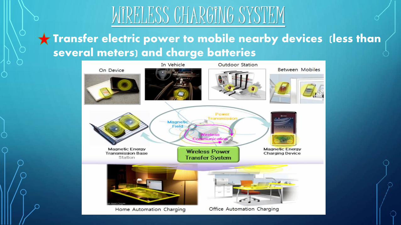
WIRELESS CHARGING SYSTEMTransfer electric power to mobile nearby devices (less than several meters) and charge batteries
OVERVIEW OF WIRELESS CHARGING SYSTEM
Wireless Charging SystemHow to transfer power and charge efficientlyDevices which have a battery
Wireless Power Transfer SystemHow to transfer power efficientlyAll electric devices
Difference from cable chargersElimination of complicated wire cablesSafety from electric shockIncreased mobilityRelatively low efficiency (about 90% efficiencyof cable chargers)
Considered frequency bands20~60 kHz80~370 kHz6.78~13.56 MHz
HOW WE CAN TRANSFER ELECTRICAL ENERGY WIRELESSLY ?
BY THE HELP OF INDUCTION PROCESS.
BY THE HELP OF MICROWAVE.
BY THE HELP OF LEASER.
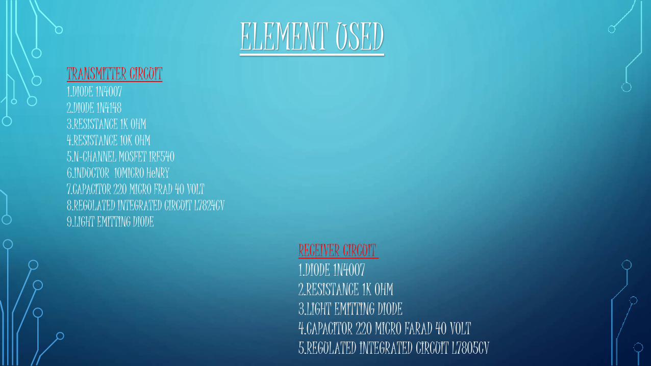
ELEMENT USED
RECEIVER CIRCUIT 1.DIODE 1N40072.RESISTANCE 1K OHM3.LIGHT EMITTING DIODE4.CAPACITOR 220 MICRO FARAD 40 VOLT5.REGULATED INTEGRATED CIRCUIT L7805CV
TRANSMITTER CIRCUIT1.DIODE 1N40072.DIODE 1N41483.RESISTANCE 1K OHM4.RESISTANCE 10K OHM5.N-CHANNEL MOSFET IRF5406.INDUCTOR 10MICRO HeNRY7.CAPACITOR 220 MICRO FRAD 40 VOLT8.REGULATED INTEGRATED CIRCUIT L7824CV9.LIGHT EMITTING DIODE
WORKING PRINCIPLE
This circuit mainly works on theprinciple of mutual inductance. Poweris transferred from transmitter toreceiver wirelessly based on theprinciple of “inductive coupling”.
“Mutual inductance” is the phenomena in which,when a current carrying conductor is placed nearanother conductor voltage is induced in thatconductor. This is because, as the current is flowing inthe conductor, a magnetic flux is induced in it. Thisinduced magnetic flux links with another conductorand this flux induces voltage in the secondconductor. Thus two conductors are said to beinductively coupled.
WHAT IS MUTUAL INDUCTANC?
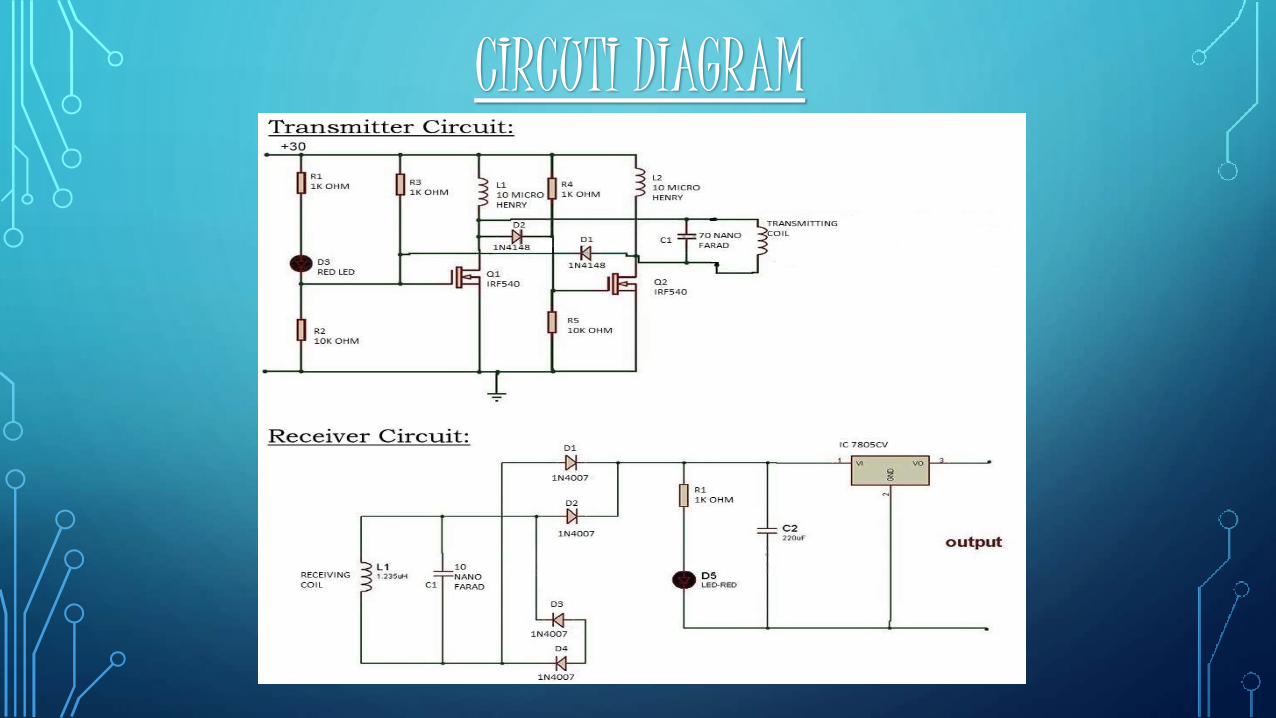
CIRCUTI DIAGRAM
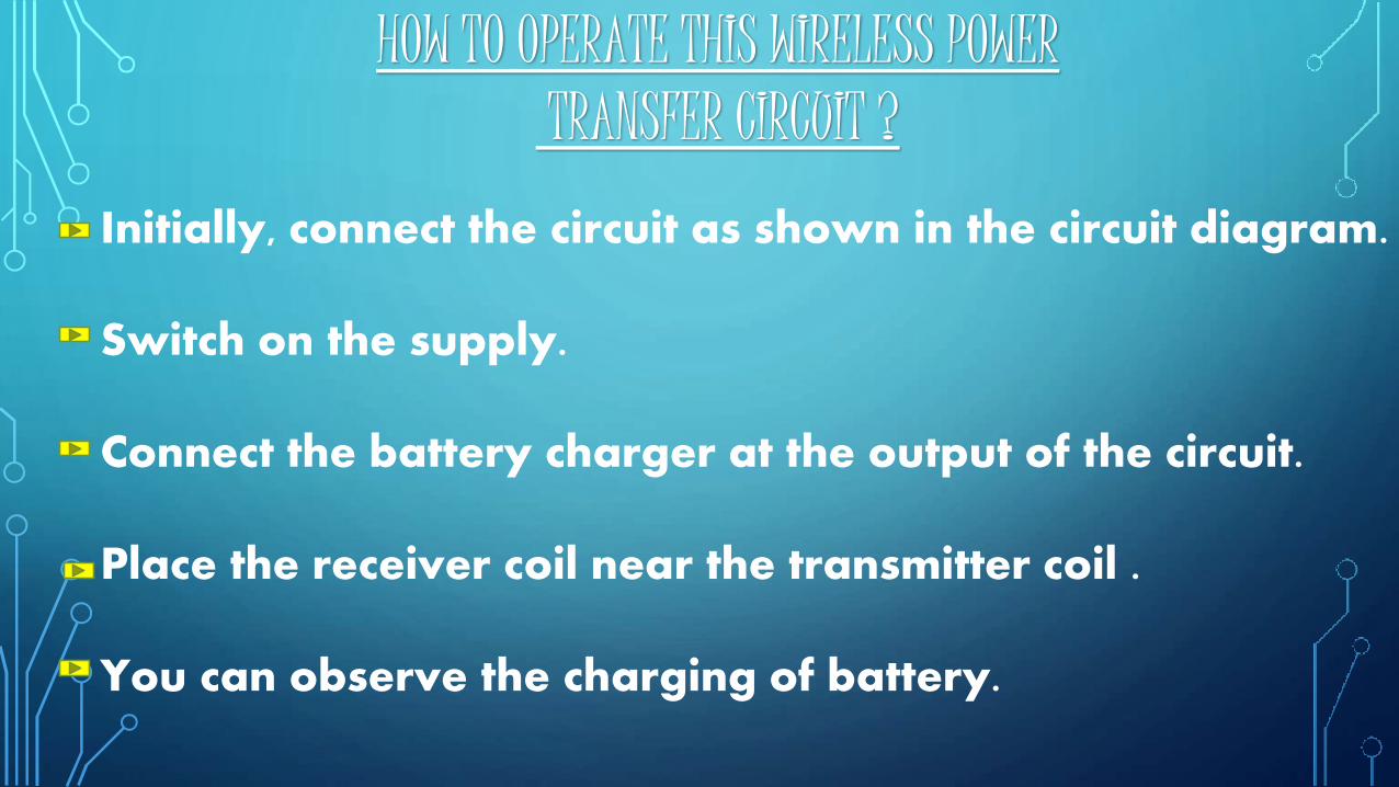
HOW TO OPERATE THIS WIRELESS POWERTRANSFER CIRCUIT ?
Initially, connect the circuit as shown in the circuit diagram.
Switch on the supply.
Connect the battery charger at the output of the circuit.
Place the receiver coil near the transmitter coil .
You can observe the charging of battery.
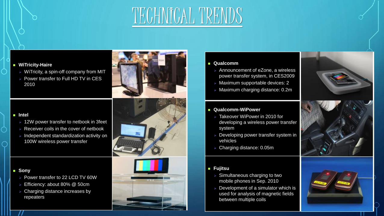
TECHNICAL TRENDS
WiTricity-Haire
WiTricity, a spin-off company from MIT
Power transfer to Full HD TV in CES
2010
Intel
12W power transfer to netbook in 3feet
Receiver coils in the cover of netbook
Independent standardization activity on
100W wireless power transfer
Sony
Power transfer to 22 LCD TV 60W
Efficiency: about 80% @ 50cm
Charging distance increases by
repeaters
Qualcomm
Announcement of eZone, a wireless
power transfer system, in CES2009
Maximum supportable devices: 2
Maximum charging distance: 0.2m
Qualcomm-WiPower
Takeover WiPower in 2010 for
developing a wireless power transfer
system
Developing power transfer system in
vehicles
Charging distance: 0.05m
Fujitsu
Simultaneous charging to two
mobile phones in Sep. 2010
Development of a simulator which is
used for analysis of magnetic fields
between multiple coils
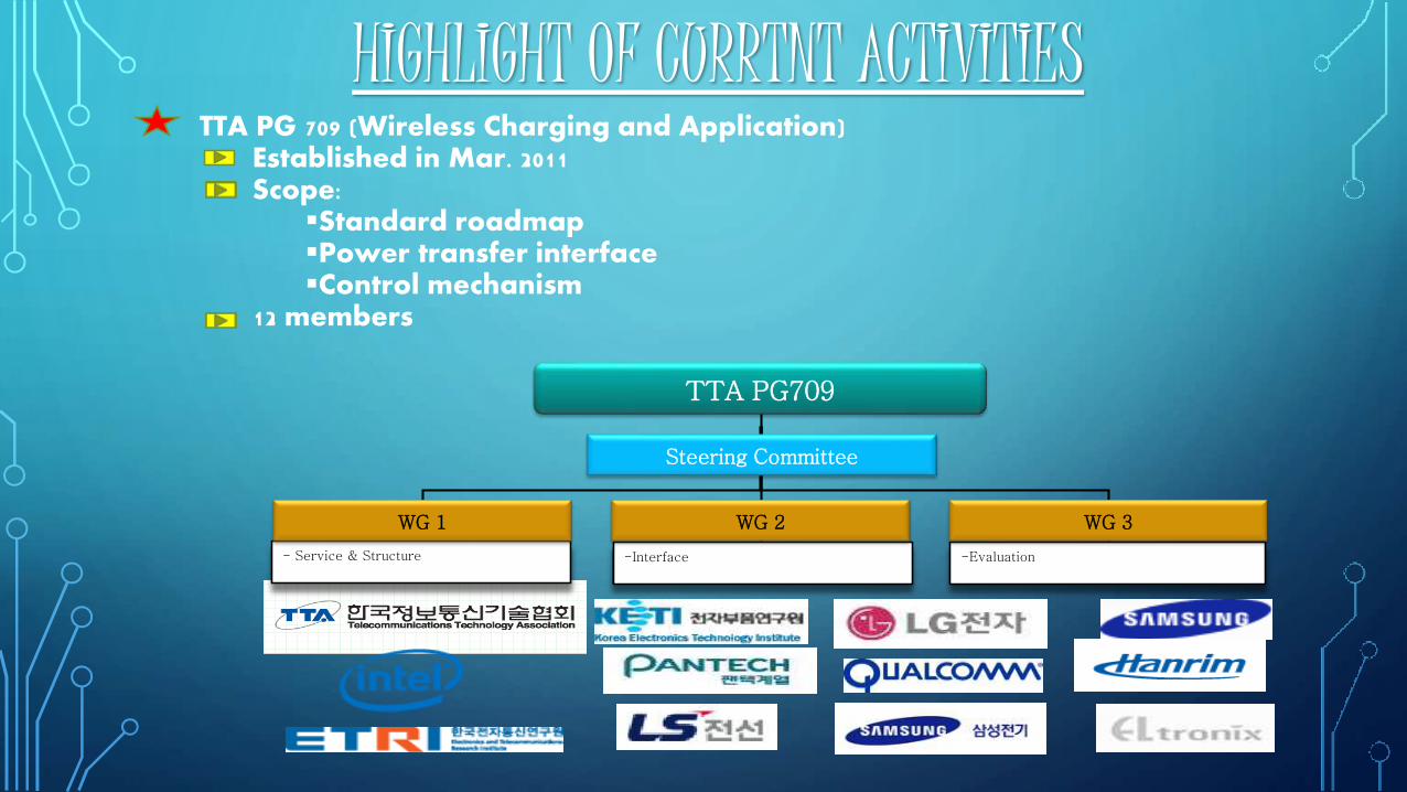
HIGHLIGHT OF CURRTNT ACTIVITIESTTA PG 709 (Wireless Charging and Application)
Established in Mar. 2011Scope:
Standard roadmapPower transfer interfaceControl mechanism
12 members
- Service & Structure -Evaluation-Interface
TTA PG709
Steering Committee
WG 1 WG 2 WG 3
WIRELESS BATTERY CHARGER ADVANTAGE
Usage of separate charger is eliminated.
Phone can be charged anywhere and anytime.
It does not require wire for charging.
Easier than plug into power cable.

WIRELESS POWER TRANSFER CIRCUIT APPLICATION
Wireless chargers can be used to charge mobiles, camerabatteries, Bluetooth headsets etc.
This can also be used in applications like car batterycharger with little modification.
This can also be used in medical devices.
CHALLANGESProduct Diversification
As market is increasing, each vendor makes the WirelessCharging system which has different structure & protocol.
Wireless Charging is possible only between systemshaving the same structure & protocol.
Frequency IssuesEach vendor considers different frequency bands forWireless Charging which disables interoperabilitybetween Wireless Charging systems
Regulation IssuesEach nation has different regulation for EMI/EMC, SAR, etc.
Standardization Activities for product diversification
System & interface
Control & management protocol
Conformance test & certification
Regulation Coordination & CompromiseFrequency bandEMI/EMCSAR
Activities toward the global harmonizationCooperation with other SDOs
Investigation of the similar activities and directions in other organizations
NEXT STEPS/ACTIONS
REFERENCE1. MIT BOSTON, U.S.A2. TSHINGHUA UNIVERSITY , CHINA3. ELECTRONIC DEVICE & CIRCUIT, BOYLSTED4. CIRCUIT THEORY, ALEXANDER & SADIKU5. SAMSUNG, INTEL, LG ,SONY6. WIKIPEDIA7. ENCYCLOPEDIA8. YOUTUBE9. ELECTRONICHUB.COM

THANK YOU


