Wireless Local Area Network I ntegration
162
Wireless Local Area Network Integration Master of Science Thesis in Communication Engineering David Khetaguri Matthieu Leon Department of Signals and Systems Communication Systems Group CHALMERS UNIVERSITY OF TECHNOLOGY Göteborg, Sweden, 2011 Master’s Thesis EX074/2011
Transcript of Wireless Local Area Network I ntegration

Wireless Local Area Network Integration
Master of Science Thesis in Communication Engineering
David Khetaguri
Matthieu Leon
Department of Signals and Systems
Communication Systems Group
CHALMERS UNIVERSITY OF TECHNOLOGY
Göteborg, Sweden, 2011
Master’s Thesis EX074/2011


The Author grants to Chalmers University of Technology the non-exclusiveright to publish the Work electronically and in a non-commercial purposemake it accessible on the Internet. The Author warrants that he/she is theauthor to the Work, and warrants that the Work does not contain text, pic-tures or other material that violates copyright law.The Author shall, when transferring the rights of the Work to a third party(for example a publisher or a company), acknowledge the third party aboutthis agreement. If the Author has signed a copyright agreement with a thirdparty regarding the Work, the Author warrants hereby that he/she has ob-tained any necessary permission from this third party to let Chalmers Uni-versity of Technology store the Work electronically and make it accessible onthe Internet.
Wireless Local Area Network Integration
DAVID KHETAGURIMATTHIEU LEON
c©DAVID KHETAGURI, 2011.c©MATTHIEU LEON, 2011.
Examiner: Fredrik Brannstrom
Masters Thesis EX074/2011Chalmers University of TechnologyDepartment of Signals and SystemsCommunication Systems GroupSE-412 96 GoteborgSwedenTel. +46-(0)31 772 1000
Department of Signals and SystemsGoteborg, Sweden, 2011

Abstract
This report summarizes a master thesis project carried out at Volvo Technol-
ogy Corporation as the final part of the Communication Engineering program
at Chalmers University of Technology. The thesis was related to Wireless Lo-
cal Area Network, which is a relevant feature for future on-board telematics
systems. An Android-based mobile-device prototype of a telematic appli-
cation was developed, and new use-cases which involve usage of a Wireless
Local Area Network were found during this thesis. Numerous use-cases were
investigated during workshops with various stakeholders, based on their ex-
perience, opinion and requirements. Also an evaluation of each use-case was
done. Development of the prototype included two parts, implementation of
communication between the telematic system and a mobile device communi-
cation, and development of a mobile application. The mobile application is
an implementation of a pre-driving checks use-case. The thesis describes how
the application was implemented and covers an overview of problems that
appeared during the process. Further, possible solutions and future work
were suggested in order to develop the final product.

Acknowledgements
We would like to express our gratitude to the In-vehicle systems group at
Volvo Technology Corporation for the really good time we had and to give
us the opportunity to perform this thesis.
A special thanks to Linda Bromander and Otto Emanuelsson for supervising
us, helping us to solve our problems, giving us valuable ideas.
We also want to thank Fredrick Anderson, who helped us to get familiar with
the system architecture, the software code and being always eager to help.
And also for answering the many questions we had.
Special thanks to Rolf Nilsson, Jonas Andersson, Christian Johansson, Jo-
hanna Karlsson and all the stakeholder we met while investigating the new
use-cases.
Sui Yutao and Fredrik Brannstrom at Chalmers for the great job in organiz-
ing and giving advices in the academic matters.
Last but not least, thanks to our families and friends for their support and
encouragement during the thesis.
iii

CONTENTS
Contents
Abstract ii
Acknowledgements iii
Contents viii
List of figures xi
List of tables xii
Acronyms xiv
1 Introduction 1
1.1 Background . . . . . . . . . . . . . . . . . . . . . . . . . . . . 1
1.2 Objectives . . . . . . . . . . . . . . . . . . . . . . . . . . . . . 1
1.3 Scope . . . . . . . . . . . . . . . . . . . . . . . . . . . . . . . 2
1.4 Method . . . . . . . . . . . . . . . . . . . . . . . . . . . . . . 2
1.5 Report structure . . . . . . . . . . . . . . . . . . . . . . . . . 3
2 Technical background 5
2.1 Challenges of smartphone programming . . . . . . . . . . . . . 5
2.2 Android programming . . . . . . . . . . . . . . . . . . . . . . 6
2.3 Wireless Local Area Network . . . . . . . . . . . . . . . . . . 6
2.3.1 Wireless Local Area Network connection modes . . . . 7
2.3.2 Wired Equivalent Privacy . . . . . . . . . . . . . . . . 7
2.3.3 Wi-Fi Protected Access . . . . . . . . . . . . . . . . . . 9
2.3.4 Wi-Fi Protected Access . . . . . . . . . . . . . . . . . . 9
2.3.5 802.11p . . . . . . . . . . . . . . . . . . . . . . . . . . 9
2.4 Controller Area Network . . . . . . . . . . . . . . . . . . . . . 10
iv

CONTENTS
2.5 User Datagram Protocol . . . . . . . . . . . . . . . . . . . . . 10
2.6 File Transfer Protocol . . . . . . . . . . . . . . . . . . . . . . 11
2.7 Socket programming . . . . . . . . . . . . . . . . . . . . . . . 12
2.8 eXtensible Markup Language . . . . . . . . . . . . . . . . . . 14
2.9 Use case . . . . . . . . . . . . . . . . . . . . . . . . . . . . . . 14
2.10 Activity diagram . . . . . . . . . . . . . . . . . . . . . . . . . 15
2.11 Virtual Private Network . . . . . . . . . . . . . . . . . . . . . 15
3 Initial system analysis 16
3.1 Telematic system description . . . . . . . . . . . . . . . . . . . 16
3.2 On-Board System overview . . . . . . . . . . . . . . . . . . . . 17
3.3 Wi-Fi adapter overview . . . . . . . . . . . . . . . . . . . . . . 18
3.4 Mobile device overview . . . . . . . . . . . . . . . . . . . . . . 20
3.5 Connection types . . . . . . . . . . . . . . . . . . . . . . . . . 20
3.5.1 Connection type 1 . . . . . . . . . . . . . . . . . . . . 20
3.5.2 Connection type 2 . . . . . . . . . . . . . . . . . . . . 21
3.5.3 Connection type 3 . . . . . . . . . . . . . . . . . . . . 22
3.5.4 Connection type 4 . . . . . . . . . . . . . . . . . . . . 23
3.5.5 Connection type 5 . . . . . . . . . . . . . . . . . . . . 24
3.5.6 Connection type 6 . . . . . . . . . . . . . . . . . . . . 24
3.5.7 Connection type 7 . . . . . . . . . . . . . . . . . . . . 25
3.5.8 Connection type 8 . . . . . . . . . . . . . . . . . . . . 25
3.6 Advantages of using a mobile device . . . . . . . . . . . . . . . 26
3.7 Requirements for the mobile application prototype . . . . . . . 27
4 Evaluation of use-cases 28
4.1 General limitations . . . . . . . . . . . . . . . . . . . . . . . . 28
4.2 Evaluation parameters . . . . . . . . . . . . . . . . . . . . . . 31
v

CONTENTS
4.3 Pre-driving checks . . . . . . . . . . . . . . . . . . . . . . . . . 33
4.3.1 Pre-driving checks . . . . . . . . . . . . . . . . . . . . 35
4.3.2 Check point . . . . . . . . . . . . . . . . . . . . . . . . 37
4.4 Remote control . . . . . . . . . . . . . . . . . . . . . . . . . . 39
4.4.1 Open/close trailer tail lift . . . . . . . . . . . . . . . . 39
4.4.2 Remote control of lights . . . . . . . . . . . . . . . . . 41
4.4.3 Temperature inside the trailer . . . . . . . . . . . . . . 41
4.4.4 Air suspension remote control . . . . . . . . . . . . . . 42
4.4.5 Truck lock/fan control/parking heater/indoor lights . . 43
4.5 Roadside assistance . . . . . . . . . . . . . . . . . . . . . . . . 43
4.6 Uploading/downloading . . . . . . . . . . . . . . . . . . . . . 44
4.6.1 Logs transmission via mobile device . . . . . . . . . . . 44
4.6.2 Data exchange using external access points . . . . . . . 45
4.6.3 Data exchange using Volvo Group access points . . . . 46
4.7 Driver coaching . . . . . . . . . . . . . . . . . . . . . . . . . . 47
4.7.1 Driver coaching/training . . . . . . . . . . . . . . . . . 47
4.7.2 Feedback from manager . . . . . . . . . . . . . . . . . 48
4.7.3 Driving coaching feedback exchange between drivers . . 49
4.8 Work Tools . . . . . . . . . . . . . . . . . . . . . . . . . . . . 50
4.8.1 Load indicator . . . . . . . . . . . . . . . . . . . . . . . 50
4.8.2 Bar codes scanning . . . . . . . . . . . . . . . . . . . . 50
4.8.3 Getting signatures . . . . . . . . . . . . . . . . . . . . 51
4.8.4 Drivers map . . . . . . . . . . . . . . . . . . . . . . . . 52
4.8.5 Arrival time estimation . . . . . . . . . . . . . . . . . . 53
4.8.6 GPS antenna from a truck . . . . . . . . . . . . . . . . 54
4.9 Existing use cases . . . . . . . . . . . . . . . . . . . . . . . . . 55
4.9.1 Time management . . . . . . . . . . . . . . . . . . . . 56
vi

CONTENTS
4.9.2 Transport management . . . . . . . . . . . . . . . . . . 57
5 Implementation 59
5.1 User Interface . . . . . . . . . . . . . . . . . . . . . . . . . . . 59
5.2 Communication . . . . . . . . . . . . . . . . . . . . . . . . . . 61
5.2.1 Laptop - mobile device . . . . . . . . . . . . . . . . . . 61
5.2.2 OBS - mobile device . . . . . . . . . . . . . . . . . . . 62
5.3 XML file description . . . . . . . . . . . . . . . . . . . . . . . 64
5.4 Extending API . . . . . . . . . . . . . . . . . . . . . . . . . . 66
5.5 Android implementation . . . . . . . . . . . . . . . . . . . . . 67
5.6 Problems . . . . . . . . . . . . . . . . . . . . . . . . . . . . . . 72
6 Conclusions 75
Reference 81
Appendix A Use cases 82
A.1 Connection . . . . . . . . . . . . . . . . . . . . . . . . . . . . 82
A.1.1 Connection between the on-board system and the mo-
bile device . . . . . . . . . . . . . . . . . . . . . . . . . 82
A.1.2 Send data to the Back-Office System via the on-board
system . . . . . . . . . . . . . . . . . . . . . . . . . . . 84
A.1.3 Send data to the Back-Office System via the mobile
device . . . . . . . . . . . . . . . . . . . . . . . . . . . 86
A.2 Remote control . . . . . . . . . . . . . . . . . . . . . . . . . . 88
A.2.1 Open/close trailer tail lift . . . . . . . . . . . . . . . . 88
A.2.2 Remote control of lights . . . . . . . . . . . . . . . . . 89
A.2.3 Temperature inside the trailer . . . . . . . . . . . . . . 92
A.2.4 Air suspension . . . . . . . . . . . . . . . . . . . . . . 95
vii

CONTENTS
A.2.5 Truck lock/fan control/parking heater/inside lights . . 98
A.3 Roadside assistance use-case . . . . . . . . . . . . . . . . . . . 105
A.4 Uploading/downloading . . . . . . . . . . . . . . . . . . . . . 108
A.4.1 Logs transmission via mobile device . . . . . . . . . . . 108
A.4.2 Data exchange using external Access Point . . . . . . . 109
A.5 Driver coaching . . . . . . . . . . . . . . . . . . . . . . . . . . 113
A.5.1 Driver coaching/training . . . . . . . . . . . . . . . . . 113
A.5.2 Feedback from manager . . . . . . . . . . . . . . . . . 118
A.5.3 Driver coaching feedback exchange between drivers . . 121
A.6 Work tools . . . . . . . . . . . . . . . . . . . . . . . . . . . . . 124
A.6.1 Load indicator . . . . . . . . . . . . . . . . . . . . . . . 124
A.6.2 Bar codes scanning . . . . . . . . . . . . . . . . . . . . 127
A.6.3 Getting signatures . . . . . . . . . . . . . . . . . . . . 129
A.6.4 Drivers map . . . . . . . . . . . . . . . . . . . . . . . . 130
A.6.5 Arrival time estimation . . . . . . . . . . . . . . . . . . 134
A.6.6 Global Positioning System antenna from the truck . . . 137
A.7 Existing use cases . . . . . . . . . . . . . . . . . . . . . . . . . 139
A.7.1 Transport management . . . . . . . . . . . . . . . . . . 139
A.7.2 Time management . . . . . . . . . . . . . . . . . . . . 143
Appendix B OBS and mobile device 146
viii

LIST OF FIGURES
List of figures
1 WEP encryption . . . . . . . . . . . . . . . . . . . . . . . . . 7
2 The four UDP header fields . . . . . . . . . . . . . . . . . . . 11
3 FTP control and data connections . . . . . . . . . . . . . . . . 12
4 Socket protocols . . . . . . . . . . . . . . . . . . . . . . . . . . 13
5 UDP server definition . . . . . . . . . . . . . . . . . . . . . . . 14
6 Telematic system overview . . . . . . . . . . . . . . . . . . . . 16
7 General configuration of the telematic system . . . . . . . . . 18
8 Mobile device - Telematic platform - Back-Office System . . . 21
9 Telematic platform - Mobile device - Back-Office System . . . 22
10 Telematic platform - Mobile device . . . . . . . . . . . . . . . 22
11 Telematic platform - Mobile device - Access point - Back-Office
System . . . . . . . . . . . . . . . . . . . . . . . . . . . . . . . 23
12 Telematic platform - Telematic platform . . . . . . . . . . . . 24
13 Back-Office System - Telematic platform - Access point . . . . 25
14 Telematic platform - Access point - Back-Office System . . . . 25
15 Telematic platform - Volvo Group access point - Back-Office
System . . . . . . . . . . . . . . . . . . . . . . . . . . . . . . . 26
16 Pre-driving checks . . . . . . . . . . . . . . . . . . . . . . . . . 34
17 Pre-driving checks . . . . . . . . . . . . . . . . . . . . . . . . . 37
18 Check point . . . . . . . . . . . . . . . . . . . . . . . . . . . . 39
19 Application user interface . . . . . . . . . . . . . . . . . . . . 60
20 The different interface of the OBS . . . . . . . . . . . . . . . . 63
21 Example of received xml file . . . . . . . . . . . . . . . . . . . 65
22 Some part of the Perl Script . . . . . . . . . . . . . . . . . . . 67
23 Lauch of predriving checks . . . . . . . . . . . . . . . . . . . . 69
24 Parameters from OBS are received . . . . . . . . . . . . . . . 69
ix

LIST OF FIGURES
25 Parameters to control at Step1 . . . . . . . . . . . . . . . . . . 70
26 Step1 is passed, step2 is failed and current step is 3 . . . . . . 70
27 Other available options for the driver . . . . . . . . . . . . . . 71
28 Submit report to back-office . . . . . . . . . . . . . . . . . . . 72
29 Connection between the OBS and the mobile device . . . . . . 83
30 Send data to the BOS via the OBS . . . . . . . . . . . . . . . 85
31 Send data to the BOS via the mobile device . . . . . . . . . . 87
32 Open/close trailer tail lift . . . . . . . . . . . . . . . . . . . . 89
33 Remote control for lights . . . . . . . . . . . . . . . . . . . . . 91
34 Temperature inside the trailer . . . . . . . . . . . . . . . . . . 94
35 Air suspension . . . . . . . . . . . . . . . . . . . . . . . . . . . 97
36 Truck lock, fan control, parking heater and inside lights . . . . 100
37 Indoor lights . . . . . . . . . . . . . . . . . . . . . . . . . . . . 101
38 Fan and parking heater control . . . . . . . . . . . . . . . . . 103
39 Truck lock . . . . . . . . . . . . . . . . . . . . . . . . . . . . . 104
40 Roadside Assistance . . . . . . . . . . . . . . . . . . . . . . . 107
41 Log transmission via mobile device . . . . . . . . . . . . . . . 109
42 Data exchange using external Access Point . . . . . . . . . . . 112
43 Driver coaching . . . . . . . . . . . . . . . . . . . . . . . . . . 117
44 Feedback from manager . . . . . . . . . . . . . . . . . . . . . 120
45 Coaching based on other drivers feedback . . . . . . . . . . . . 123
46 Load indicator . . . . . . . . . . . . . . . . . . . . . . . . . . . 126
47 Bar-code scanning . . . . . . . . . . . . . . . . . . . . . . . . . 128
48 Getting signatures . . . . . . . . . . . . . . . . . . . . . . . . 130
49 Drivers map . . . . . . . . . . . . . . . . . . . . . . . . . . . . 133
50 Arrival time estimation . . . . . . . . . . . . . . . . . . . . . . 136
51 GPS antenna from truck . . . . . . . . . . . . . . . . . . . . . 138
x

LIST OF FIGURES
52 Transport management . . . . . . . . . . . . . . . . . . . . . . 142
53 Coaching based on other drivers feedback . . . . . . . . . . . . 145
54 OBS and mobile . . . . . . . . . . . . . . . . . . . . . . . . . . 146
xi

LIST OF TABLES
List of tables
1 Explanation of the XML tags . . . . . . . . . . . . . . . . . . 65
xii

Acronyms
Acronyms
AES Advanced Encryption Standard.
AP Access Point.
API Application Programming Interface.
BOS Back-Office System.
CAN Controller Area Network.
CLI Command Line Interface.
CRC Cyclic Redundancy Check.
DTJ Driver Time Justification.
ECU Electronic control unit.
FTP File Transfer Protocol.
GPRS General Packet Radio Service.
GPS Global Positionning System.
GSM Global System for Mobile Communications.
HMI Human Machine Interface.
IEEE Institute of Electrical and Electronics Engineers.
IETF Internet Engineering Task Force.
IP Internet Protocol.
xiii

ACRONYMS
IV Initialisation Vector.
MAC Media Access Control.
OBS On-Board System.
OS Operating System.
SDK Software Development Kit.
SSID Service Set IDentifier.
TFTP Trivial File Transfer Protocol.
TKIP Temporal Key Integrity Protocol.
UDP User Datagram Protocol.
USB Universal Serial Bus.
VPN Virtual Private Network.
WEP Wired Equivalent Privacy.
WLAN Wireless Local Area Network.
WPA Wi-Fi Protected Access.
WPA2 Wi-Fi Protected Access 2.
XML eXtensible Markup Language.
xiv

1 INTRODUCTION
1 Introduction
1.1 Background
Future generations of telematic solutions will provide Wireless Local Area
Network (WLAN) in trucks, due to the increasing demand of widely used
mobile devices [1]. Mobile applications will provide an alternative way to
access main functions of the telematic system as well as provide completely
new functions that are not feasible to implement on a classical on-board sys-
tem.
The current telematic system consists of two sub-systems, a Back-Office Sys-
tem (BOS) and an On-Board System (OBS). The two components cooperate
in order to control and monitor vehicles and drivers. The vehicle telematic
functions include vehicle tracking, fleet management, emergency warning sys-
tem for vehicles, fuel saving techniques, messaging, etc.
OBS is connected to vehicle Electronic control units (ECUs) and serves as
gateway between a vehicle and BOS. Another function of OBS is to provide
a user-interface, allowing users to interact with the system.
BOS enables keeping track of the vehicles, send software updates, as well
as provide data storage and user interface (web portal for administrators,
dispatchers etc.).
1.2 Objectives
The objective of this thesis is primarily to integrate WLAN technology in a
telematic systems accomplishing the following steps:
1

1 INTRODUCTION
• find promising use-cases which utilizes WLAN;
• implement a WLAN connection between the OBS and a mobile device,
i.e. modify the existing OBS code and implement a User Datagram
Protocol (UDP) server on a mobile device in order to send data using
UDP;
• analyze whether the available WLAN solution provided by the onboard
device is good enough for an integration of mobile devices;
• analyze how on-board WLAN shall be available to the end-user, analyze
available security protocols and how credentials should be managed;
• develop an Android-based prototype and implement one of the found
use-cases on a mobile device.
1.3 Scope
Any mobile device (smartphones, tablets, laptops etc.) may communicate
with the OBS via WLAN, but this thesis considers only an Android-based
mobile device due to time limitations. For the same reason not all of the
found use-cases will be implemented. Regarding the software for the OBS,
we modified the necessary parts of the existing code to establish simplex
communication between the OBS and a mobile device. Duplex communica-
tion requires additional code modification on both the OBS and the mobile
device side.
1.4 Method
In the initial phase we got familiar with existing hardware and software in
order to get a clear understanding of the telematic system functionality and
2

1 INTRODUCTION
architecture, as well as roles of the system stakeholders. Since it was decided
to implement the use-case in an Android-based mobile device, we started to
get familiar with Android programming.
In order to find use-cases and evaluate the available WLAN solution, cus-
tomers’ and engineers’ requirements and engineers’ feedback about existing
limitations had to be found. Thus, we arranged numerous workshops with
various stakeholder involved in each step of the product line. In addition we
met hauler company representatives and drivers to get the end-user point of
view and requirements. After analyzing the feedback from those workshops
we obtained some ideas of possible use-cases. Having this knowledge we were
able to write activity diagrams and develop an Android-based mobile telem-
atic platform prototype.
After implementing communication between the OBS and the mobile device,
we chose to implement a Pre-driving checks use-case.
1.5 Report structure
This thesis report is divided into six main parts. The Introduction (Chapter
1) defines the objectives and gives some background to the reader. Then the
Technical background part (Chapter 2) describes the main technology and
methods used in the thesis work. The purpose of this part is to give the
technical knowledge needed by the reader to understand the content of this
report. The Initial system analysis (Chapter 3) describes the current system
architecture, and possible WLAN type identified. In Evaluation of use-cases
(Chapter 4) , a description and evaluation of the use-case that we found is
presented. The Implementation part (Chapter 5) describes how the applica-
3

1 INTRODUCTION
tion was implemented and the problems that we encountered. Finally, in the
Conclusions (Chapter 6) we summarize the main thesis results and discuss
future activities that can be done to release the use-case implementation as
a finished product.
4

2 TECHNICAL BACKGROUND
2 Technical background
This part describes technologies and methods used while accomplishing this
master thesis project.
2.1 Challenges of smartphone programming
When developing a mobile application there are many challenges that appear
in comparison with development of regular software. These include [2]:
• Variety of mobile operating systems (iOS, Android, Blackberry, Win-
dows Mobile, etc) and device models implies development of several
versions of the same application;
• Screen size limitations cause a problem with information profusion;
• Keyboard size limitations;
• Battery life limitations;
• Processing power limitations;
• Memory limitations compared to desktop or laptops;
• Lower bandwidth and network coverage limitations;
• Internet connections costs;
• Environmental influence on mobile device(relief, precipitation, power
lines, network overload, etc.).
5

2 TECHNICAL BACKGROUND
2.2 Android programming
Android is a free, open-source Operating System (OS) for mobile devices as
well as an open-source development platform for creating mobile applications.
The Android Software Development Kit (SDK) includes Application Pro-
gramming Interfaces (APIs) for such services as Global Positionning System
(GPS), camera, audio, network connections, Wi-Fi, bluetooth, accelerome-
ters, touchscreen, and power management. These API libraries significantly
simplify development of applications that involve the use of device hardware
[3].
The Android OS openness allows handset manufacturers to use and modify
it, that, undoubtedly, makes Android the most promising OS for all mobile
device areas. As a result, the Android platform took a leading position on
the smartphone market in 2010 [4].
2.3 Wireless Local Area Network (WLAN)
This section will give a brief overview of the Wireless Local Area Network
(WLAN) technology. A WLAN is a wireless connection protocol that have
different connection modes, own encryption and authentication protocols.
WLAN belongs to the 802.11 specifications developed by the Institute of
Electrical and Electronics Engineers (IEEE). The most common standards of
802.11 are b and g. Both of those standards work on the 2.4GHz frequency
bands. However 802.11g got a much faster theoretical maximum rate of
54Mbps whereas 802.11b supports rate up to 11Mbps. In addition 802.11g
supports the latest wireless security standards including Wi-Fi Protected
Access 2 (WPA2).
6

2 TECHNICAL BACKGROUND
2.3.1 WLAN connection modes
A WLAN network has two different connection modes for accessing internet
or communication between clients: infrastructure and ad-hoc.
The infrastructure network topology represents client-server mode, where
clients(also called stations) communicate using a central device called wireless
access point. An access point shows its presence by broadcasting beacons in
a regular interval which allow clients to discover the access point.
An Ad-hoc network is decentralized and not based on a pre-existing routing
infrastructure. Instead, the network allows stations to directly communi-
cate with each other without using an access point. An ad-hoc station, that
initializes a connection, starts sending beacons, which are needed to main-
tain synchronization among the stations. Other ad-hoc stations can join the
network after receiving a beacon.
2.3.2 Wired Equivalent Privacy (WEP)
Wired Equivalent Privacy (WEP) is the first standard that was introduces
to secure wireless networks. The following scheme (Figure 1) explains the
encryption of a clear text [5].
Figure 1: WEP encryption
7

2 TECHNICAL BACKGROUND
A shared key is associated to each access point and this key is used by all
users of the access point. A unique Initialisation Vector (IV) is used for each
packet. The RC4 cipher is used for encryption and the output of the RC4 is
xored with the plain text + Cyclic Redundancy Check (CRC). The encrypted
message is the IV key (in clear) plus the ciphertext. This implementation
has many issues. First let’s imagine that two ciphertexts (c1 and c2 ) are
xored. This will result in Equation 1, where p1 and p2 are plaintexts, and
where b is a stream.
c1⊕
c2 = (p1⊕
b)⊕
(p2⊕
b) = p1⊕
p2⊕
b⊕
b = p1⊕
p2 (1)
p1 and p2 can be found by analysis of plaintexts. To avoid this problem
IVs are used, thus different streams are created. The only problem is that
IV is a 24 bit number, so a busy Access Point (AP) will use all possible IV
in less than one hour, moreover reusing IVs is allowed! Another weakness in
WEP is the use of CRC, when we modify text; it’s possible to predict how
to modify the CRC, which is not the case with hash.
It’s also possible to find the key stream used by the access point. When
a user is connecting to the access point the AP is sending a clear text chal-
lenge. The station is responding to that request with the resulting ciphertext.
By xoring the challenge and the encryption result a key stream is recovered
[6].
WEP has a lot of other vulnerabilities, but it’s obvious from those two vulner-
abilities that WEP should never be used. To improve WEP, Wi-Fi Protected
Access (WPA) was created. Hardware that supports WEP also supports
WPA (only a firmware update is required).
8
2 TECHNICAL BACKGROUND
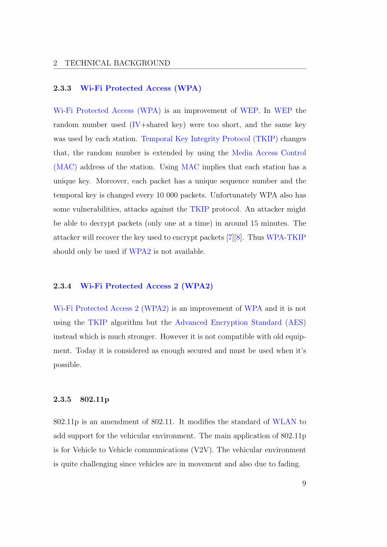
2.3.3 Wi-Fi Protected Access (WPA)
Wi-Fi Protected Access (WPA) is an improvement of WEP. In WEP the
random number used (IV+shared key) were too short, and the same key
was used by each station. Temporal Key Integrity Protocol (TKIP) changes
that, the random number is extended by using the Media Access Control
(MAC) address of the station. Using MAC implies that each station has a
unique key. Moreover, each packet has a unique sequence number and the
temporal key is changed every 10 000 packets. Unfortunately WPA also has
some vulnerabilities, attacks against the TKIP protocol. An attacker might
be able to decrypt packets (only one at a time) in around 15 minutes. The
attacker will recover the key used to encrypt packets [7][8]. Thus WPA-TKIP
should only be used if WPA2 is not available.
2.3.4 Wi-Fi Protected Access 2 (WPA2)
Wi-Fi Protected Access 2 (WPA2) is an improvement of WPA and it is not
using the TKIP algorithm but the Advanced Encryption Standard (AES)
instead which is much stronger. However it is not compatible with old equip-
ment. Today it is considered as enough secured and must be used when it’s
possible.
2.3.5 802.11p
802.11p is an amendment of 802.11. It modifies the standard of WLAN to
add support for the vehicular environment. The main application of 802.11p
is for Vehicle to Vehicle communications (V2V). The vehicular environment
is quite challenging since vehicles are in movement and also due to fading.
9

2 TECHNICAL BACKGROUND
2.4 Controller Area Network (CAN)
The Controller Area Network (CAN), or CAN-bus is a message-based pro-
tocol, designed for communication between ECUs within a vehicle. This
multi-master broadcast serial bus standard allows all nodes to send and re-
ceive messages. ECUs connected to CAN network through a host processor
and a CAN controller. ECUs can transmit when the bus is free, otherwise
the message with dominant id has higher priority and is transmitted first.
CAN networks provide bit rates up to 1 Mbit/s. In order to transfer data
between ECUs such protocols as J1939, ISO14229 and ISO15765 are used.
2.5 User Datagram Protocol (UDP)
The User Datagram Protocol (UDP) is one of the major transport layer pro-
tocols. UDP is connectionless, i.e. doesn’t require established connection
to send data. This way the protocol provides a basic transmission model,
avoiding complicated handshake dialogues and therefore makes transmission
faster. Another advantage of UDP is compatibility with packet broadcasting
and multicasting. However, the drawback of the UDP protocol is its unrelia-
bility, since there might be corruptions during data transmission and there is
no way to confirm data receipt. The data unit of UDP is a datagram, which
has its own 64 bits long header (Figure 2) [9].
10

2 TECHNICAL BACKGROUND
Figure 2: The four UDP header fields
2.6 File Transfer Protocol (FTP)
The File Transfer Protocol (FTP) is a network protocol used for file exchange
via Internet and has a client-server architecture. The protocol has a two-port
structure, which employs two ports to connect client and server. The server’s
port 21 is used for a control connection which is responsible for establishing
the connection and session administration. The server’s port 20 is used for
data connection to transfer data (Figure 3). A data connection could be
opened by the client (passive mode) or by the server (active mode). There
are three possible modes for data transfer: stream, block and compressed
mode. The first mode implies data transmission as a continuous stream
without processing. The second mode breaks data into several blocks. And
the third mode compresses data before transmitting [10].
11

2 TECHNICAL BACKGROUND
Figure 3: FTP control and data connections
2.7 Socket programming
Sockets are used to enable applications to send and receive data. Each pro-
tocol such as UDP or TCP has their own socket type. Since UDP was used
in this thesis, we will discuss mainly about UDP sockets. There are two main
types of sockets, datagram sockets and stream sockets. The first one is used
for UDP and the second one for TCP. A datagram socket provides a best
effort service, messages up to 65500 bytes in length can be sent. There are
three parameters to identify a socket, an IP address, a protocol and a port.
Figure 4 explains the socket protocol. Each protocol has his own port num-
bered from 1 to 65535. Each UDP socket is associated to one port. Thus
each socket is unique. Applications are connected to a socket. The same
application can used many different socket. Sockets can also be shared by
different applications [11].
12

2 TECHNICAL BACKGROUND
Figure 4: Socket protocols
In Java to send data via UDP, you first create an InetAddress to define the
Internet Protocol (IP) address which the server is listening on. Then you
create a datagram socket. A datagram socket has two elements, the server
port and the InetAddress previously defined. Now the socket is defined. The
packet that is to be received must also be defined using a DatagramPacket
object in Java. The datagram packet is used to define the size of the buffer.
Then you can use the Java method “receive” to receive the data that is sent
via UDP (Figure 5). Sending data can be done in a similar way by using the
method “send”. When defining the port and the IP address, the port and IP
identify the destination of a sent packet, they define the source of a received
packet [12].
13

2 TECHNICAL BACKGROUND
InetAddress serverAddr = InetAddress.getByName("0.0.0.0");
// Creating the socket
socket = new DatagramSocket(1024, serverAddr);
// packets content is put in a buff
byte[] buf = new byte[1500];
// initialized received packet
DatagramPacket packet = new DatagramPacket(buf, buf.length);
Figure 5: UDP server definition
2.8 eXtensible Markup Language
The eXtensible Markup Language (XML) is a mark-up language to describe
data that has a tree structure. An XML file is composed of many XML tags.
Between each tag some text may be added. The tags must be balanced,
which means that each open tag has to be closed [13]. The tags should
not overlapped, which means that the parent tag should be closed after the
children tags [14]. The data contained in the XML file can be extracted using
a parser. XML can be used to define the graphic interface in Android and
also to define a data structure of elements sent between using UDP.
2.9 Use case
A use case describes a set of interactions between actors and the system, to
deliver the service that satisfies the actors’ goals. Actors represent users or
other systems and their roles while interacting with the system. They initiate
a use case and it is successfully accomplished after a desired goal is achieved.
A complete set of use cases specifies all possible ways of the system use, and
therefore defines all behavior required of the system [15].
14

2 TECHNICAL BACKGROUND
2.10 Activity diagram
Activity diagrams are visual illustration of workflows of stepwise activities
and actions. A complete workflow description will have a basic flow, which
describes general sequence of activity steps and alternative flows, which are
variations in the steps of a workflow. Activity diagrams textually define a
structure of a workflow, using statements and conditions of various kinds,
such as if, if-then-else, or do-until [16].
2.11 Virtual Private Network (VPN)
The Internet Engineering Task Force (IETF) defines a VPN by “emulation
of a private Wide Area Network facility using IP facilities” [17].
Basically, it is possible to communicate between two points using the tun-
neling technology. Three security mechanisms are also used:
• Encryption: The data can be read only by a user that knows how to
decrypt them.
• Authentication: Authentication is used to be sure that the sender
and the receiver are not a third-party person. One example of authen-
tication is to use a username and a password.
• Authorization: Authorization is the process of accepting or denying
the access of the resource [18].
15

3 INITIAL SYSTEM ANALYSIS
3 Initial system analysis
The purpose of the analysis part is to describe the telematic system used
in this thesis, including architecture, interaction between its various parts
and their functions. The chapter also covers a description of the used Wi-
Fi adapter functions and explains how to use WLAN to provide interaction
between the telematic system and a mobile device or an AP. The final part
of the analysis specifies requirements for the mobile device application.
3.1 Telematic system description
The telematic system used in this thesis project is a theoretical model of a
system, which is based on today’s system with available WLAN capability.
The telematic system consists of two parts, the on-board system OBS and
the back-office system BOS. The two components cooperate via a wireless
channel in order to control and monitor vehicles and drivers. Vehicle telem-
atic functions include vehicle tracking, fleet management, emergency warning
system for vehicles, fuel saving techniques, messaging, etc. (Figure 6).
Figure 6: Telematic system overview [19]
16

3 INITIAL SYSTEM ANALYSIS
3.2 On-Board System (OBS) overview
The On-Board System (OBS) is connected to different networks and infor-
mation providers in the vehicle and exchanges data with the BOS system via
a wireless communication channel (Global System for Mobile Communica-
tions (GSM)/General Packet Radio Service (GPRS)/WLAN). The on-board
system provides an user-interface, so that a user will be able to interact with
the system. The OBS has two functions. First, it serves as a gateway on-
board and stores information from ECUs. Second, the OBS is used as a
service platform which has the role of a Human Machine Interface (HMI)
(Appendix B).
The BOS can keep track of the OBS, send software updates, as well as
provide data storage and user interface (for administrators, dispatchers etc.).
The addition of WLAN onboard , investigated in this thesis, enables users to
use mobile devices (with required application) as an alternative way to access
main functions of the telematic system. Moreover, mobile device applications
can provide completely new functions that are not feasible to implement on
a classical OBS.
Two WLAN connection modes are supported: ad-hoc or infrastructure. A
mobile device can be connected via WLAN to the OBS and then the OBS
can be connected via GSM/GPRS to the BOS portal. The OBS can also
be connected to an external access point. This external access point can be
connected to the BOS using VPN (Figure 7). The OBS can’t be used as an
access point in these connections.
17

3 INITIAL SYSTEM ANALYSIS
Application Programming Interface (API) is a particular set of rules and
specifications used as an interface between software programs and enables
their interaction [20]. The on-board API is represented by a XML file that
contains various vehicle information. Nowadays, the content of the API is
broadcasted via the Universal Serial Bus (USB) interface.
Figure 7: General configuration of the telematic system
3.3 Wi-Fi adapter overview
The Wi-Fi adapter in the OBS used in this project has been developed by
wi2wi [21]. The W2SW0001 WLAN chip is a complete wireless subsystem
featuring full 802.11 b/g WLAN capability. This device operates in the
18

3 INITIAL SYSTEM ANALYSIS
2.4Ghz band and has optimized radio frequency and electrical design for
better performance in co-existence with other wireless standards.
Since all smartphones are quite recent, they all support 802.11g. It could be
a good solution to consider using only 802.11g and not considering 802.11b,
since 802.11g supports higher speeds than 802.11b.
In terms of security, the chip supports the following standards [22]:
• WEP encryption (64 bit/128 bit)
• WPA TKIP security
• WPA2
As mentioned before, WEP and WPA security algorithms don’t offer enough
security. Most smartphones support WPA2 which, therefore, should be used
all the time. The available Wi-Fi solution does not support Radius server
protocol. Another problem is that some of APs don’t support WPA2 at all.
In this case WPA-TKIP should be considered and it must be decided whether
it is secure enough for the certain use-case. In other words, how sensitive the
transmitted data is.
The Wi-Fi adapter supports both ad-hoc and infrastructure mode but func-
tions only as a station. We think that it would be better to use a chip that
can be used as an AP to make it easier for the end user to connect to the
telematic system. Some other functions of the chip are the following:
• IEEE power save mode
• Deep sleep mode
19

3 INITIAL SYSTEM ANALYSIS
• Rate adaptation (to improve bit rate and the robustness of the data, it
is possible to modify the quality of the radio channel by adapting the
modulation and coding scheme)[23]
• Bluetooth coexistence
3.4 Mobile device overview
In this thesis a HTC Desire mobile device was used. The requirements for
the mobile device was to support WLAN in order to connect to the OBS,
sufficient storage to save all the data used by the driver is preferable. Some
hardware function of the phone (camera, GPS, etc.) are also needed for some
use-case. This phone runs a Android 2.2 system with a 1GHz CPU. For more
details about other specifications, please refer to [24]
3.5 Connection types
After analyzing the system and its main components, we mapped the pos-
sible connection types. For the connection types we consider both ad-hoc
and infrastructure mode even if Android is not currently supporting ad-hoc
networks. The purpose of finding all the connection types is that for each
use-cases there are different ways to connect.
3.5.1 Connection type 1
A mobile device communicates with the telematic platform via WLAN. The
telematic platform exchanges information with the BOS via GSM/GPRS.
This connection type relies on the communication channel between the OBS
and the BOS. In this connection type Volvo Group is responsible for this
communication part (Volvo Group has it’s own communication channel),
20

3 INITIAL SYSTEM ANALYSIS
which means that the end user doesn’t need to have a data plan on his
mobile. Data plan (needed to get a data access, for browsing on internet,
receiving emails...) covers and limits amount of sent/received data (providers
limit data amount to some value for a period based on the contract). Ad-hoc
or infrastructure mode can be used between mobile device and the telematic
platform (Figure 8).
Figure 8: Mobile device - Telematic platform - BOS(Connection type 1)
3.5.2 Connection type 2
Today’s telematic system is not designed to use other SIM card than the one
provided by Volvo Group. In this connection type the telematic platform
communicates with a mobile device via WLAN. The mobile device will com-
municate with the BOS using 3G of the mobile device. In this connection
type, the GSM/GPRS connection of the OBS is not used anymore, the end
user is paying for the data. This means that Volvo Group is not in charge
of the GSM/GPRS channel anymore, which can be good since Volvo Group
is not a mobile operator. The advantage for Volvo Group is that the cost
is reduced since all data traffic will be payed by the user to his operator.
Moreover if the communication channel is broken, Volvo Group will not be
in charge of fixing the issue. In addition, this solution is more convenient for
the end-user who can choose the mobile operator. This connection type can
also be used as an alternative to the connection type 1 if the channel between
21
3 INITIAL SYSTEM ANALYSIS
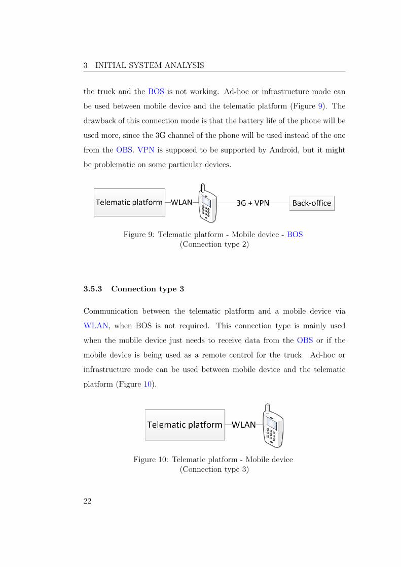
the truck and the BOS is not working. Ad-hoc or infrastructure mode can
be used between mobile device and the telematic platform (Figure 9). The
drawback of this connection mode is that the battery life of the phone will be
used more, since the 3G channel of the phone will be used instead of the one
from the OBS. VPN is supposed to be supported by Android, but it might
be problematic on some particular devices.
Figure 9: Telematic platform - Mobile device - BOS(Connection type 2)
3.5.3 Connection type 3
Communication between the telematic platform and a mobile device via
WLAN, when BOS is not required. This connection type is mainly used
when the mobile device just needs to receive data from the OBS or if the
mobile device is being used as a remote control for the truck. Ad-hoc or
infrastructure mode can be used between mobile device and the telematic
platform (Figure 10).
Figure 10: Telematic platform - Mobile device(Connection type 3)
22

3 INITIAL SYSTEM ANALYSIS
3.5.4 Connection type 4
The telematic platform communicates with a mobile device via WLAN. The
mobile device communicates with BOS via an external access point using
WLAN. This connection type doesn’t require any GSM/GPRS connection,
which means that exchanging data with the BOS is almost costless. This
connection type can be really useful if the driver needs to make OBS soft-
ware update or exchange large data with the BOS or with support services
(support needs logs file from the truck to find the issue(s) if something is
wrong). The mobile device is used as an intermediate, this can be really
useful if the truck doesn’t have any service platform (i.e. any user interface),
then the communication is done in two times. One part between the OBS
and the mobile and the second part is between the mobile and the BOS. The
limitation of this use-case is that the driver needs to find an AP, which might
not be fully compatible with the OBS. Ad-hoc or infrastructure mode can be
used between mobile device and the telematic platform. Infrastructure mode
is used between the mobile and the BOS (Figure 11).
Figure 11: Telematic platform - Mobile device - Access point - BOS(Connection type 4)
23

3 INITIAL SYSTEM ANALYSIS
3.5.5 Connection type 5
Communication between two telematic platforms via WLAN. OBS to OBS
connection should be considered for future use-cases (i.e. alternative to 802.11p).
This connection type might be useful to find other truck in the neighborhood.
Ad-hoc mode is used in this connection type, one of the telematic platform
has to initiate the communication (Figure 12).
Figure 12: Telematic platform - Telematic platform(Connection type 5)
3.5.6 Connection type 6
The telematic platform is connected to the BOS via GSM/GPRS and to an
available external access point via WLAN for such service as cheap internet
surfing when there is no fixed data plan. There is no found use-cases for this
type of connection, but however it gives the way for further ideas. Infrastruc-
ture mode is used between the telematic platform and the AP (Figure 13).
24

3 INITIAL SYSTEM ANALYSIS
Figure 13: BOS - Telematic platform - Access point(Connection type 6)
3.5.7 Connection type 7
The telematic platform is connected to the BOS via an external access point
using WLAN channel. Infrastructure mode is used in this connection type
(Figure 14). The main advantage of using an AP is that communication
cost, in our case, is lower compared to the use of the GSM/GPRS channel.
However, limitation is that there should be available AP. For more details
see 4.6.2, 4.6.3.
Figure 14: Telematic platform - Access point - BOS(Connection type 7)
3.5.8 Connection type 8
Telematic platform is connected to the BOS via “Volvo Group” AP using
WLAN channel. We propose to use a Volvo Group AP, which means that
there will be no compatibility problem with the OBS. Volvo Group will decide
where to install them. The solution could be to install Volvo Group APs in
workshops or in hauler companies’ parking. The GSM/GPRS connection is
disabled, as soon as the truck arrives in the coverage area of a Volvo Group
25

3 INITIAL SYSTEM ANALYSIS
AP and the WLAN channel is used to download large data from BOS to OBS
or exchange data that is required only once per day. Infrastructure mode is
used between the OBS and the AP (Figure 15).
Figure 15: Telematic platform - Volvo Group access point - BOS(Connection type 8)
3.6 Advantages of using a mobile device
Using a mobile device gives a new range of possible advantages in compari-
son to the embedded telematic system. It will allow Volvo Group to be on
the edge of technology within the business area, since mobile applications
provide a completely new approach to telematic platform use. A mobile de-
vice will combine multiple devices and functions: being a temporal or even
a permanent alternative to the on-board screen, remote control of the truck,
smartphone and its functions, GPS system and 3G channel. The last will
allow customers to choose their own mobile operator, which might reduce
communication costs. Nowadays, Volvo Group provides only one mobile op-
erator per continent (Telenor for Europe). Portability of a mobile device
makes it attached to a driver rather than to a vehicle. Therefore the driver
will be able to access information and control his vehicle even being outside
of the truck, which makes the haulers’ business more efficient and drivers’
26

3 INITIAL SYSTEM ANALYSIS
lives more comfortable. Moreover, a mobile application can be made more
or less open, thus the company could be able to customize the application to
suits its needs. Also using a smartphone may cost less for a hauler company
than buying a Service Platform.
Using a mobile device has also some disadvantages, which are described in
4.1 General limitations.
3.7 Requirements for the mobile application prototype
Design requirements are based on the description of the system, its compo-
nents and the thesis project objectives. They are divided into mobile device
and OBS parts.
The mobile device should be able to communicate with the OBS. A mo-
bile application that can receive data from the OBS and the corresponding
transmission protocol should be implemented.
The OBS should be able to send data to a mobile device. Also, the OBS
API should be extended and ported to the WLAN interface, i.e. parameters
relevant to the selected use-case should be added in the API and be trans-
mitted to the mobile device.
A pre-driving checks use-case shall be implemented. It’s also important to
have a user-friendly application.
27

4 EVALUATION OF USE-CASES
4 Evaluation of use-cases
This section covers general limitations and evaluation of found use cases
which consider using mobile device connected to the OBS via WLAN or the
OBS connected to the external AP via WLAN. The purpose of evaluation is
to highlight advantages and limitations of use-cases. First, general limitations
that are typical for all use cases are explained. Further each of use cases is
evaluated based on chosen parameters.
4.1 General limitations
• Network security vulnerability: Using a mobile device in a use-
cases decreases a level of network security. While WLAN connection
is secured enough, the GSM/GPRS connection makes a mobile device
vulnerable. Hence attackers can access the OBS and confidential data.
If an attacker succeeds to take control of the mobile that means he can
see the data that are broadcasted by the OBS, he can also transmits
fake request to the telematic system or try any kind of networking
attack.
• WLAN security: As it was mentioned previously, WEP and WPA
are not secured enough. Those network are extremely vulnerable, it’s
possible for almost everyone to hack them really quickly using some
tools like “Aircrack” [25]. Therefore WPA2 has to be used in order
to prevent unauthorized access to the confidential data. In this case
wireless channel can be considered as secured and shouldn’t be seen as
a limitation, at least nowadays. It has to be decide if other security
protocol should be considered in some case, but in our point of view it’s
a bad idea. Proper wireless network security protocols (WEP, WPA,
28

4 EVALUATION OF USE-CASES
WPA2) have to be used in order to provide sufficient level of security
against attackers, so that to be sure that nobody will be able to have
access to confidential data.
• Limited coverage of WLAN network: Limitations caused by lim-
ited network coverage area (38 meters indoor and 140 meters outdoor)
and its influence on data rate should be considered [26].
• Ad-hoc mode absence: Android doesn’t support ad-hoc connection
mode yet. Therefore it will be impossible to use ad-hoc connection
mode with Android based mobile devices [27]. For more details see
5.2.2. However, a mobile device can be set up as an access point and
the OBS Wi-Fi chip can be a client. Otherwise Wi-Fi chip can be
modified to serve as access point as well.
• Fragility of a mobile device: Since users may use a mobile device
outside, such aspects as water resistance and mechanical protection
should be considered. The most vulnerable component is a mobile
device screen. Nowadays, there is a number of protective cases, but an
evaluation of these have not been included in this thesis.
• User-friendly interface (accessibility): Due to particularities of
the market area, the application should be implemented in a way to
minimize the number of possible actions from a drivers side as well as
to be as user-friendly as possible. Besides, profusion of information
context should be avoided, due to the screen size limitation of mobile
devices.
• High cost for traffic: Many use-cases require regular data exchange
between the OBS and the BOS, it may cause extra expenditures, due
29

4 EVALUATION OF USE-CASES
to high price of the OBS - BOS connection.
• High Power Consumption: Wi-Fi has high power consumption in
comparison to other wireless standards (ZigBee) [28].
• Mobile device constraints: Mobile devices have various constraints
caused by their compact design. Examples of these constraints are lim-
ited screen size, disk space, RAM and processor speed. Besides, short
battery life of a mobile device should be taken into consideration. Since
a mobile device will be used during whole day, it should be possible to
charge it inside the truck.
• Low performance of mobile device GPS: Mobile device GPS
antenna has a low performance inside the truck, which can be a problem
to obtain GPS coordinates. One possible solution is to use a GPS
antenna of truck and send it to a mobile device.
• Mobile device OBS duplex communication: Most of the use-
cases require duplex communication between the OBS and a mobile
device. However, nowadays there is only simplex communication from
the OBS to a mobile device available. Therefore duplex communication
has to be implemented.
• ECUs code modification: Some use-cases will require to commu-
nicate with extra ECUs, which implies significant modification of both
OBS and ECUs code.
• Mobile device back-office communication: If we want to com-
municate from mobile device directly to the BOS (without using the
OBS), the BOS protocol have to be implemented on the phone.
30

4 EVALUATION OF USE-CASES
• Impact of use-cases on driving skills: Since it is forbidden to
use mobile device while driving in many countries, the applications
should probably be locked when the truck is moving [29]. However, if
we consider a mobile device as embedded/fixed, it might be legal to
use it while driving.
• Mobile device loss: We should consider risks related to loosing/for-
getting/stealing of a mobile device. If a driver doesn’t have it, he might
not be able to achieve his tasks. However, there are still evident ad-
vantages of using mobile device, since its associated to a certain driver
rather then to a truck.
• Compatibility: It is important to consider variety of operational
systems, brands and models of mobile devices while implementation of
mobile applications. Solution could be a certain mobile device chosen
by Volvo Group and provided to a customer together with a truck.
• Deployment: There are different way to deploy the application,
could be installed on an hardware provided by Volvo Group, or if Volvo
Group doesn’t provide the hardware it can be available via the Android
Market [30] or via a Volvo Group official web-page.
4.2 Evaluation parameters
The evaluation is done for the use cases which consider using mobile device
connected to the OBS via WLAN (ad-hoc mode) or the OBS connected to
the external AP via WLAN (infrastructure mode). The process of evaluation
is based on parameters that are relevant to a certain use-case and irrelevant
parameters are not considered. A description of each use case is included in
the evaluation and further information, such as activity diagrams, main and
31

4 EVALUATION OF USE-CASES
alternative flows are available in the Appendix A.
A complete list of evaluation parameters follows:
• Description and actuality
A brief description of a use case together with benefits and advantages
it provides.
• Feasibility
The feasibility evaluation is intended to estimate whether a proposed
use case is technologically and legally feasible in order to adequately
perform the given assignment and solve the posed problem.
• Security
This part will cover possible risks for the network security and vulner-
abilities that exist or can appear due to connection types and factors
particular to a certain use-case.
• Safety
The safety evaluation considers how implementation and application
of a use-case will affect the safety of a driver and the environment.
Various scenarios of use-case application will be assessed as well.
• Compliance
Compliance assesses whether a use-case conforms to a rule (such as a
specification, policy, standard or law). Difference in rules and regula-
tions based on country should be considered.
• Actors and stakeholders
List of possible actors and stakeholders that are involved in a use-case.
32

4 EVALUATION OF USE-CASES
• Resource constraints
Is the hardware powerful enough to be used for a specific use case?
Which is the minimum configuration for the mobile device (processor
speed, memory, disk space, wireless card specifications)?
• Efficiency
Evaluation of resource consumption during implementation and usage
of proposed use-case. This can include evaluation of data traffic con-
sumption, energy consumption and time efficiency.
• Backup
Where data related to a use-case should be stored, in aspects of con-
fidentiality, safety and ability to recover the original should be consid-
ered.
4.3 Pre-driving checks
Traffic safety requires the driver to carry out a daily inspection. The driver
should therefore get into the habit to walk around the vehicle and carry
out certain routine checks before starting the day’s shift (Figure 16). This
daily check can reveal faults, and prevent possible disruption once out on the
road. The main problem is that pre-driving checks take a long time to be
accomplished (around 20min), and therefore most drivers don’t do it often
enough. The use-case will allow a driver to access information from onboard
indicators while being outside of a truck, which will minimize time spent
for pre-driving checks. Moreover the use-case provides an additional level of
safety by automatic detection of existing problem. A driver will be able to
control lights from the mobile device, see additional information from vehicle
33

4 EVALUATION OF USE-CASES
indicators and send the pre-driving checks report to the BOS with a detailed
description of any problem. In order to make a detailed description, the
application will use mobile device functions such as camera, audio recorder
and communication capabilities.
Figure 16: Pre-driving checks
Possible connection types: Connection type 1, Connection type 2, Con-
nection type 4
Safety: There are cases when certain parameters require “manual” check,
because data extracted by mobile device can be insufficient or wrong for mak-
ing a decision to continue driving. Therefore physical presence of a driver on
certain point is the only way to check some parameters.
Feasibility: The use-case requires duplex communication between the OBS
and a mobile device. Additional modification of both OBS and ECUs’ code
has to be done in order to implement communication between these com-
ponents. Moreover, the software of the OBS should be modified in order to
extract certain ECUs parameters from CAN bus.
34

4 EVALUATION OF USE-CASES
Resource constraints and backup: Pre-driving checks reports includ-
ing photos, audio files and additional descriptions will be stored in the BOS.
Decision of period of the data storage should be made by the client company.
Compliance: Since there are no general rules for pre-driving checks in the
European Union, a document developed by Volvo Group was used as a basis
[31].
Actors and Stakeholders: A driver, service center staff, the BOS.
4.3.1 Pre-driving checks
The flows for the pre-driving checks are presented bellow, the corresponding
activity diagrams can be found on Figure 17.
Main flow events:
1.1 This is a general use case event indicating that the application is
started.
1.2 Driver logs into the system
The driver logs into the system.
1.3 Driver turns engine on
The driver turns engine on.
1.4 OBS sends indicators data to Mobile Device
This task is performed if the mobile device is connected to the OBS.
OBS starts to transmit UDP datagram which includes various param-
eters inside the truck including dash-board indicators.
35

4 EVALUATION OF USE-CASES
1.5 Mobile Device sends command to turn on the lights to OBS
A driver chooses to remotely turn on the lights using a mobile device.
1.6 Lights are turned on
After the OBS receives the command, it is forwarded to corresponded
ECU that turns on lights
1.7 Sub-tasks 1, 2
A driver performs pre-driving checks on check points 1 and 2 (See: 4.3.2
Check point).
1.8 Sub-tasks 3, 4, 5, 6, 7, 8, 9, 10
A driver performs pre-driving checks on check points 3-10 if the truck
has a trailer (See: 4.3.2 Check point).
1.9 Report is sent to Back-office
Pre-driving checks report including additional comments, taken pic-
tures and recorded sounds is sent to the BOS when a driver finishes
pre-driving checks on all check points (See: A.1.2).
Alternative flow events:
2.1 Mobile Device attempts to connect to OBS
In case there is no connection between a mobile device and the OBS,
alternative use case is performed (See: A.1.1).
3.1 Sub-tasks 6, 7, 8, 9, 10
A driver performs pre-driving checks on check points 6-10 if the truck
doesn’t have a trailer (See: 4.3.2 Check point).
36

4 EVALUATION OF USE-CASES
Figure 17: Pre-driving checks
4.3.2 Check point
The flows for the check-point subtask are presented bellow, the corresponding
activity diagrams can be found on Figure 18.
Main flow events:
37

4 EVALUATION OF USE-CASES
1.1 This is a general use case event indicating that the application is
started.
1.2 Driver checks truck parameters on a position
The driver checks the list of parameters relevant to a certain check
point (Figure 16).
1.3 Driver takes a picture using Mobile Device
In case one of the parameters on a certain check-point doesn’t pass, the
driver can take a picture using the embedded mobile device camera.
The picture(-s) will be included in the Pre-driving checks report.
Alternative flow events:
2.1 Driver writes additional comments
In case one of the parameters on a certain check-point doesn’t pass,
the driver can write additional comments describing the problem. The
comments will be included in the Pre-driving checks report.
3.1 Driver records a sound using Mobile device
A driver can make audio recording in case there is an uncommon sounds
while the engine is on. The audio recording will be included in the Pre-
driving checks report.
38

4 EVALUATION OF USE-CASES
Figure 18: Check point
4.4 Remote control
4.4.1 Open/close trailer tail lift (See: A.2.1)
The driver will use the mobile device to remotely control the trailer tail lift
(open, close, manage platform position). The driver should also have infor-
39

4 EVALUATION OF USE-CASES
mation in the mobile device about the status of trailer doors (open or closed).
If the trailer doors are open while driving the driver will receive a notification.
Possible connection types: Connection type 3
Resource constraints: WLAN technology has long critical response time,
while the use-case requires low latency. Also, WLAN technology requires
long time to establish connection.
Feasibility: The use-case requires duplex communication between the OBS
and the mobile device, in order to send data from the mobile device to the
OBS. Modification of both OBS and ECUs code is required to communicate
with extra ECUs. Device connection using WLAN technology takes 3-5 sec-
onds [32]. Therefore, using WLAN technology in this use case is not labour
safe. Zigbee technology would be the best alternative, since establishing con-
nection takes 30 ms and the technology has lower critical response time, i.e.
time that system takes to react on a given output [33]. However, the OBS is
not equipped with Zigbee chip and nowadays there is no mobile device on the
market which supports this technology. In order to solve the problem with
device connection time in WLAN technology, proper transmission algorithm
of bit sequence should be developed. So that air suspension is adjusted only
while there is connection between devices. Taking it all into consideration,
Volvo Group has to make a decision of the wireless technology to be used.
Actors and Stakeholders: A driver, the mobile application, the OBS.
40

4 EVALUATION OF USE-CASES
4.4.2 Remote control of lights (See: A.2.2)
The driver can remotely switch on/off lights of the truck using the mobile
device. Thus, there will not be a need to control lights from the truck during
pre-driving checks.
Possible connection types: Connection type 3
Feasibility: The use-case requires duplex communication between the OBS
and the mobile device, in order to send data from the mobile device to the
OBS. Modification of both OBS and ECUs code is required to communicate
with extra ECUs.
Actors and Stakeholders: A driver, the mobile application, the OBS.
4.4.3 Temperature inside the trailer (See: A.2.3)
In case trailers are refrigerated, the mobile device will display the inside tem-
perature. The driver will be able to set a reference temperature, and get a
warning if the trailer temperature is above this reference.
Possible connection types: Connection type 1, Connection type 2
Feasibility: To send data between the mobile device, the OBS and the
BOS, the use-case requires duplex communication between the OBS and the
mobile device.
Actors and Stakeholders: A driver, the mobile application, the OBS,
the BOS.
41
4 EVALUATION OF USE-CASES
4.4.4 Air suspension remote control (See: A.2.4)
The mobile device can remotely adjust the position of the truck towards
loading/unloading platform using air suspension. Also, the driver can use
predefined levels that are stored on the mobile device to simplify work.
Possible connection types: Connection type 3
Resource constraints: WLAN technology has long critical response time,
while the use-case requires low latency. Also, WLAN technology requires
long time to establish connection.
Feasibility: The use-case requires duplex communication between the OBS
and the mobile device, in order to send data from the mobile device to
theOBS. Modification of both OBS and ECUs code is required to commu-
nicate with extra ECUs. Device connection using WLAN technology takes
3-5 seconds [32]. Therefore, using WLAN technology in this use case is not
labour safe. Zigbee technology would be the best alternative, since estab-
lishing connection takes 30 ms and the technology has lower critical response
time, i.e. time that system takes to react on a given output [33]. However,
OBS is not equipped with Zigbee chip and nowadays there is no mobile de-
vice on the market which supports this technology. In order to solve the
problem with device connection time in WLAN technology, proper transmis-
sion algorithm of bit sequence should be developed. So that air suspension
is adjusted only while there is connection between devices. Taking it all into
consideration, Volvo Group has to make a decision of the wireless technology
to be used.
42

4 EVALUATION OF USE-CASES
Actors and Stakeholders: A driver, the mobile application, the OBS.
Backup: Pre-defined levels should be stored both on the truck’s OBS and
the driver’s mobile device.
4.4.5 Truck lock/fan control/parking heater/indoor lights (See: A.2.5)
The mobile device is used as a remote control to open/close the truck, to
control a fan/parking heather inside and to control indoor lights. Status of
these parameters will be displayed as well.
Possible connection types: Connection type 3
Feasibility: The use-case requires duplex communication between the OBS
and the mobile device, in order to send data from the mobile device to the
OBS. Modification of both OBS and ECUs code is required to communicate
with extra ECUs.
Actors and Stakeholders: A driver, the mobile application, the OBS.
4.5 Roadside assistance (See: A.3)
The mobile application will allow a driver to request roadside assistance in
short period of time. The application will automatically send GPS coor-
dinates of a driver together with vehicle specifications and required services
(tire, fuel filter, battery, mechanical problem, etc.) to the roadside assistance
company. Required services request will be done based on data extracted
from OBS. The application will enable a driver to request roadside assis-
tance also while not being inside the truck. Besides, a driver will be able to
43

4 EVALUATION OF USE-CASES
use mobile device capabilities to take a picture, make an audio recording or
write additional comments, which will allow to specify existing problem in
case of an accident.
Possible connection types: Connection type 1, Connection type 2
Feasibility: The use-case requires duplex communication between OBS and
a mobile device. Additional modification of both OBS and ECUs’ code has
to be done in order to implement communication between these components.
While image quality is high, a sound quality might not be enough to recog-
nize existing problem.
Actors and Stakeholders: A driver, the BOS, the OBS, the mobile appli-
cation.
Backup: Data received from a driver is stored in the BOS until the problem
is solved.
4.6 Uploading/downloading
4.6.1 Logs transmission via mobile device (See: A.4.1)
If the GSM/GPRS connection between the OBS and the BOS doesn’t work,
the user can send onboard system logs to the Volvo Group support office
via the mobile device. This function will save a lot of time both for a client
company and the Volvo Group support office, since the logs can be used to
investigate the problem and find a solution before taking the truck out of
operation.
44

4 EVALUATION OF USE-CASES
Possible connection types: Connection type 2
Feasibility: The use-case requires duplex communication between OBS and
a mobile device in order to send the request to download onboard system logs.
Actors and Stakeholders: A user, the Volvo Group support office, the
OBS, the mobile application.
Backup: A copy of the onboard system logs should be stored in the Volvo
Group support office until the problem is fixed. Decision of period of the
data storage should be made by the Volvo Group support office.
4.6.2 Data exchange using external access points (See: A.4.2)
Nowadays it is quite expensive to send large scale data via GSM/GPRS
channel between the BOS and the OBS (such as OBS and Service platform
software updates, navigation system updates, vehicle data, etc.). In order to
reduce communication expenditures, it should be possible to use the WLAN
channel between the OBS and an external AP connected to the BOS via
VPN. In the same way drivers can upload required information from the
truck to the BOS.
Possible connection types: Connection type 7
Security: VPN protocol should be used for security purposes. Besides,
some of external APs might not support WPA2, while WEP and WPA are
not secured enough. Therefore, Volvo Group has to decide whether to use
45

4 EVALUATION OF USE-CASES
public APs or not, since they might not provide sufficient level of network
security for the sensitive data exchange. As a result, an attacker may have an
access to the sensitive data. In case the Service platform is absent, the use-
case requires duplex communication between the mobile device and the OBS
in order to connect to the Volvo Group AP and make data exchange possible.
Actors and Stakeholders: A driver, the BOS, the OBS, the mobile appli-
cation.
4.6.3 Data exchange using Volvo Group access points (See: A.4.2)
Usually it is quite complicated to use external access points due to compati-
bility issues. Hauler companies (or Volvo Group service centers) can purchase
Volvo Group APs and mount these in parking area for trucks. Volvo 3P Cor-
poration can send software updates to the hauler’s back office and then the
Volvo Group APs will forward them to the parked trucks. In the same way
drivers can upload required information from the truck to the BOS. The main
benefit is simplified updating process via WLAN and reduced communication
expenditures for Volvo Group due to the use of free WLAN channel instead
of expensive GSM/GPRS, taking into consideration size of transmitted data.
Possible connection types: Connection type 8
Feasibility: A Volvo Group AP solution should be developed and installed.
Volvo Group has to decide where to install Volvo Group APs. In case the
access points are installed in the haulers’ offices, all responsibilities between
Volvo Group and the client should be carefully managed. It should be de-
cided what kind of data should be exchanged between the OBS and the
46

4 EVALUATION OF USE-CASES
Volvo Group AP (OBS and Service platform software updates, vehicle data,
onboard system logs, fault codes and other information from the truck).
Actors and Stakeholders: A driver, the BOS, a hauler office/the Volvo
Group service center, the OBS.
4.7 Driver coaching
4.7.1 Driver coaching/training (See: A.5.1)
The purpose of this function is to decrease fuel consumption. The mobile ap-
plication will evaluate driving based on different parameters (vehicle speed,
rpm, fuel consumption, slope of a road, avoiding rough braking, etc.) and
support the driver with advices on driving technique to achieve maximum
fuel economy. At the end of a trip the driver can get a performance score
and personal feedback, which will help drivers to improve their trip score.
Possible connection types: Connection type 1, Connection type 2
Feasibility: To send data from the mobile device to the OBS and then
to the BOS, the use-case requires duplex communication between the OBS
and the mobile device.
Actors and Stakeholders: A driver, the BOS, the OBS, the mobile appli-
cation.
Efficiency: The mobile application will be constantly turned on and use
WLAN, which will significantly increase energy consumption of a mobile de-
47

4 EVALUATION OF USE-CASES
vice.
Backup: Performance score database should be stored in the BOS, allowing
all drivers to have access to this information. Decision of period of the data
storage should be made by the client company.
4.7.2 Feedback from manager (See: A.5.2)
The application will enable the driver to receive performance feedback from
a manager regarding Driver coaching/training (See: 4.7.1) and Transport
Management (See: 4.9.2), which will improve cooperation between driver
and manager. This is required since drivers and managers don’t have regular
meetings. This function will enable management to trace driver coaching
performance as well as to motivate drivers to use driver coaching efficiently.
Possible connection types: Connection type 1, Connection type 2, Con-
nection type 4, Connection type 6
Feasibility: To send data from the mobile device to the OBS and then
to the BOS, the use-case requires duplex communication between the OBS
and the mobile device.
Actors and Stakeholders: A driver, a manager, the mobile application,
the OBS, the BOS.
Backup: Feedback history database should be stored in the BOS, allow-
ing the driver to have access to this information. Decision of period of the
data storage should be made by the client company.
48

4 EVALUATION OF USE-CASES
4.7.3 Driving Coaching feedback exchange between drivers (See: A.5.3)
After having received feedback from Driver coaching/training (See: 4.7.1),
information is sent to other trucks’ data storage via the BOS, so that the
application can give advice about fuel efficiency on certain roads. Having
Driver Coaching feedback from other drivers in advance will help the driver
to avoid the same mistakes that were previously made by others within/out-
side the company.
Possible connection types: Connection type 1, Connection type 2
Feasibility: To send data from the mobile device to the OBS and then
to the BOS, the use-case requires duplex communication between the OBS
and the mobile device. The coaching instructions database should contain
the instructions, which will be gathered by a company. During some period
of time the BOS should only capture the results of the same trips and leave
only the best, based on fuel consumption efficiency.
Actors and Stakeholders: A driver, the BOS, the mobile application,
the OBS.
Efficiency: The mobile application will be permanently turned on and use
WLAN, which will significantly increase energy consumption of a mobile de-
vice.
Backup: Driving coaching feedback database should be stored in the BOS,
allowing all drivers to have access to this information.
49

4 EVALUATION OF USE-CASES
4.8 Work Tools
4.8.1 Load indicator (See: A.6.1)
Drivers need to have access to the trailer’s load information, since trailers
have weight limitations. Now, when a driver is loading a trailer, he has to go
up regularly in the truck to check the weight of the trailer which is not really
convenient. The idea is to display the information available inside the truck
on the mobile device screen. An alarm should be displayed if the trailer is
overloaded.
Possible connection types: Connection type 1, Connection type 2, Con-
nection type 4
Feasibility: To send data between the mobile device, the OBS and the
BOS, the use-case requires duplex communication between the OBS and the
mobile device.
Actors and Stakeholders: A driver, the mobile application, the OBS,
the BOS.
4.8.2 Bar codes scanning (See: A.6.2)
Drivers often have to scan bar codes to trace goods during delivery. The idea
based on this use case is to take a picture of the bar codes with the camera
of the mobile device. Then the image has to be processed to keep only the
bar code and extract information from it. This data is transmitted from the
mobile device to the OBS via the WLAN interface and then forwarded to
the BOS.
50

4 EVALUATION OF USE-CASES
Possible connection types: Connection type 1, Connection type 2, Con-
nection type 4
Feasibility: To send bar-codes to the BOS, the use-case requires duplex
communication between the OBS and a mobile device. The criteria that de-
termines whether bar code was scanned correctly should be developed.
Actors and Stakeholders: A driver, the BOS, the OBS, the mobile appli-
cation.
Backup: Data received from a driver is stored in the BOS. Decision of
period of the data storage should be made by the client company.
4.8.3 Getting signatures (See: A.6.3)
A driver can ask a customer to confirm delivery by signing on the mobile
device. This document is then sent to OBS and then forwarded to the BOS.
Possible connection types: Connection type 1, Connection type 2, Con-
nection type 4
Feasibility: To send bar-codes and signatures to the BOS, the use-case
requires duplex communication between OBS and a mobile device. Besides
the smartphone should have a touch screen to support signing possibility.
Actors and Stakeholders: A driver, the BOS, the OBS, the mobile appli-
cation.
51

4 EVALUATION OF USE-CASES
Backup: Data received from a driver is stored in the BOS. Decision of
period of the data storage should be made by the client company.
4.8.4 Drivers map (See: A.6.4)
A mobile device application will show locations and schedules of the driver
and other drivers of the same company on a map. Drivers’ GPS locations and
schedules will be sent to the BOS, and the BOS will reply by giving locations
and schedules of other drivers. This application can be useful in cases when
drivers travel in one group and it is crucial to be in certain places together.
Therefore, when some drivers are stuck in a traffic jam or experiences some
technical problems, the rest of drivers will be aware of this. Also, the use-case
can be combined with Arrival time estimation (See: 4.8.5), allowing drivers
to see arrival times of each other. Another area of the applications use is not
directly related to professional purposes. The application can make drivers
life nicer. If a driver sees that his fellow colleague is close to him, they can
have lunch or have overnight stop at the same place. The application will
include a chat between drivers, as well as enable requesting the schedule of
other drivers from the BOS.
Possible connection types: Connection type 1, Connection type 2
Feasibility: To send data from the mobile device to the OBS and then
to the BOS, the use-case requires duplex communication between the OBS
and the mobile device.
Actors and Stakeholders: A driver, the BOS, the OBS, the mobile appli-
52

4 EVALUATION OF USE-CASES
cation.
Efficiency: The use-case requires constant updates of all drivers location,
which implies regular data exchange among the mobile device, the OBS and
the BOS. This will significantly increase data traffic and energy consumption
of the mobile device caused by the use of WLAN. The solution is to increase
the period of updates and add manual update button.
Backup: The last updates of the drivers’ GPS coordinates and schedules
should be stored in the BOS in order to be available for another drivers on
request.
4.8.5 Arrival time estimation (See: A.6.5)
This function will provide the driver with approximate time left to drive to
destination. This function will enable estimating time more accurately than
the one available in a navigation system, since it will combine navigation sys-
tem information on mobile device with Time Management (See: 4.9.1),Trans-
port Management (See: 4.9.2).
Possible connection types: Connection type 1, Connection type 2
Feasibility: Driving Coaching feedback exchange between drivers use-case
should be implemented first, since it will give more precise arrival time es-
timation. The use-case requires duplex communication between OBS and a
mobile device.
Actors and Stakeholders: A driver, the BOS, the OBS, the mobile appli-
53

4 EVALUATION OF USE-CASES
cation.
Efficiency: The use-case requires constant updates of all drivers location,
which implies regular data exchange among the mobile device, the OBS and
the BOS. This will significantly increase data traffic and energy consumption
of the mobile device caused by the use of WLAN. The solution is to increase
the period of updates.
Backup: The estimated arrival time should be sent to and stored in the
BOS in order to be available for another drivers on request.
4.8.6 GPS antenna from a truck (See: A.6.6)
Higher power of the truck’s GPS antenna compared to the one available on
mobile device will allow to recover more accurate GPS coordinates and then
use them on the mobile device’s navigation system.
Possible connection types: Connection type 3
Feasibility: A navigation system for trucks has to be developed on the
mobile device, since there is very few solution for trucks available nowadays.
The use-case requires duplex communication between the OBS and the mo-
bile device.
Actors and Stakeholders: A driver, the OBS, the mobile application.
Efficiency: GPS application is expected to be used constantly, therefore
will significantly increase energy consumption of the mobile device due to
54

4 EVALUATION OF USE-CASES
the use of WLAN.
4.9 Existing use cases
This cluster covers functions that already exist in Volvo Group telematic
platform. However, they are modified in a way to suit the mobile platform.
Before evaluating the functions for the mobile device platform, we give a
brief description of already existing functions.
Driver Time Management: the purpose of the function is to support the
driver and the BOS in supervising, planning and monitoring driving time.
In most markets, government legislation regulates the time truck drivers
spend driving and resting. The rules and legislations that should be applied
based on the territory/market, will be monitored. Warnings can be shown
to the driver when a rule is about to be violated and an alarm can be raised
when a rule has been violated. The criteria for warnings and alarms can be
configured by the BOS.
Driver Time Justification (DTJ): The purpose of this function is to let the
driver justify the non-driving time in a more detailed way compared to using
only the legally defined drivers activities (driving, working, resting and wait-
ing). When the reported activity is either working, resting or waiting the
driver can provide additional information to what is done during that time.
For instance it could be loading, fueling, cleaning, traffic jam, etc. the BOS
defines those Driver Time Justification (DTJ) activities.
Order management: The function is used to send orders from the BOS to
the vehicle. An order consists of one or several tasks. The driver reports the
55

4 EVALUATION OF USE-CASES
status of each task and order to the BOS. A task also contains the address
coordinates to be used by a navigation system.
4.9.1 Time management (See: A.7.2)
This function will combine existing Driving Time Management and DTJ and
make it available on the mobile device. The mobile device will display legally
defined activities received from the tachograph (driving, working, resting and
waiting) and will allow the driver to report DTJ activities when a driver is
outside the truck. Hence, the driver will be able to create/edit/read DTJ ac-
tivities from the mobile device and only read legally defined activities. Also,
the application will be able to notify/warn the driver when time of activities
is about to expire. This function can be extended to GSM/GPRS so that
the driver will have information about the time outside of the truck area.
This functionality should be used together with the Transport Management
(See: 4.9.2).
Possible connection types: Connection type 1, Connection type 2
Feasibility: In order to send data from the mobile device to the OBS and
then to the BOS, the use-case requires duplex communication between the
OBS and the mobile device.
Efficiency: The mobile application will be constantly turned on and use
WLAN, which will significantly increase energy consumption of the mobile
device.
Compliance: The rules and regulations that should be applied depend
56

4 EVALUATION OF USE-CASES
on the territory or market in which the truck is currently being used. The
default rules should be based on EU regulations.
Actors and Stakeholders: A driver, the mobile application, the OBS,
the BOS.
4.9.2 Transport management (See: A.7.1)
The mobile application implements on a mobile device already existing Order
Management function. This will allow the driver to use the function being
outside of the truck. The function will help the driver with deliveries. The
driver should be able to get information about destination to deliver goods,
to accept a delivery, to notify of the delivery and read out the delivery sched-
ule. The driver also should be able to communicate via messaging with the
BOS.
Possible connection types: Connection type 1, Connection type 2
Feasibility: To send data from the mobile device to the OBS and then
to the BOS, the use-case requires duplex communication between the OBS
and the mobile device. BOS protocols have to be implemented on the mobile
device in case of direct communication between the mobile device and the
BOS (without using the OBS).
Efficiency: The mobile application will be constantly turned on and use
WLAN, which will significantly increase energy consumption of a mobile de-
vice.
57

4 EVALUATION OF USE-CASES
Compliance: The rules and regulations that should be applied depend
on the territory or market in which the truck is currently being used. The
default rules should be based on EU regulations.
Actors and Stakeholders: A driver, the mobile application, the OBS,
the BOS.
58

5 IMPLEMENTATION
5 Implementation
Once all the use-cases had been mapped, it was decided to implement a pro-
totype of the pre-driving checks use case. The use case is implemented as
a mobile application that conforms to Volvo Group policy and provides an
additional level of safety. The main purpose of the use-case is to help the
driver to check the safety of the truck before driving. While the prototype is
Android-based, the real product could be implemented in all possible plat-
forms. The application has been developed using a real device: HTC Desire.
The code was written to be as general as possible and work correctly on
all Android devices. Due to time limitations and difficulties in creating an
interface that suits all device, some parts might only display correctly on
models with the same screen size as HTC Desire. The implementation has
been done in several steps:
• first, the main menu user interface was developed;
• then the connection with the OBS was established;
• finally, the use case itself was implemented.
5.1 User Interface
Before starting developing the user interface, we considered some important
requirements which are specific to driver activities:
• first, the interface must be really intuitive since some truck drivers
might not be really familiar with smartphones;
• another requirement is to take in account the peculiarities of the hauler
business (use big buttons since the driver might use the application with
gloves, etc.);
59

5 IMPLEMENTATION
• then ,the application should automatically lock some use-cases while
the truck is moving for safety reasons (not implemented for the proto-
type);
• finally, the user interface should be Volvo Group branded, i.e. have
Volvo Group logo and certain colors.
The main page of the user interface shows the main function of the appli-
cations. Those functions are clusters that the found use-cases were subdi-
vided into (Remote Control, Roadside Assistance, Driver Coaching, Trans-
port management, etc.). Our use case appears inside the corresponding clus-
ter (Figure 19).
Figure 19: Application user interface
60

5 IMPLEMENTATION
5.2 Communication
One of the main purposes of this thesis was to enable data transfer between
the OBS and the mobile device. Due to time limitation we have considered
only simplex communication from the OBS to the mobile device . Of course,
duplex communication should be implemented in the future. Communication
was established in two steps:
• first, communication between a laptop (to simulate the client) and the
mobile device;
• second, communication between the OBS and the mobile device.
Since Android doesn’t support adhoc mode, the mobile was used as an access
point in all the simulations and the client was either the PC or the OBS
depending on the test that we were doing.
5.2.1 Laptop - mobile device
To test the ability of the mobile to receive data from an external device, it
was decided to use the FTP protocol. First, an FTP server for Android OS
(SwiFTP) was installed on the mobile device and an FTP client was imple-
mented on the laptop. Eventually the mobile device was able to receive data
from the laptop and display it. Since the OBS uses the UDP protocol to
broadcast datagrams, the next step was to implement a UDP client on the
laptop and UDP server on the mobile device. Since the OBS had 192.168.52.1
IP address and used port 3536 to broadcast datagrams, we assigned the UDP
server to listen on 192.168.52.255:3536 address. Then a datagram socket was
initialized. The application listens on that port all the time until the driver
quits the application.
61

5 IMPLEMENTATION
The UDP protocol was chosen to transmit data from the OBS since it is
able to broadcast data in real time. Since the OBS has a relatively low
transmission period (from 1 to 60 seconds), loss of one datagram will not
have any influence. Hence, a high level of reliability was not required.
Received information was saved as an xml file and could be extracted by
an application based on the needs of it’s use case. As a result, it was possible
to receive and display information on the mobile device. The following step
was to work with the real hardware.
5.2.2 OBS - mobile device
The first thing before sending data from the OBS to the mobile device, was
to ensure that the communication channel was established between the de-
vices. Ad-hoc mode connection was supposed to be used. However, we found
out that Android doesn’t support ad-hoc mode. After some investigation we
found two possible solutions. One solution is to modify the Android OS. But
this solution would not work on all devices, moreover the devices needs to be
rooted(i.e. give superuser access to files that are normally read only). Also,
this solution could have been possible for this thesis but not for commercial
purpose, since most users will not allow an application to modify their OS.
As an alternative solution, we decided to use the mobile device as a mobile
AP. In order to connect the OBS to the mobile device’s network, we used a
telnet session.
While testing the different parameters for establishing the communication
part, we didn’t use any security protocol. Those protocols are supported by
the WLAN device drivers but we didn’t implement them for the Command
62

5 IMPLEMENTATION
Line Interface (CLI). Security protocols must be used in an actual product.
The purpose of this thesis was to develop a prototype and be able to show
that a mobile device can receive and use information broadcasted by the
OBS. Security should be considered in the future.
We have also tested that an ad-hoc connection worked between a computer
and the OBS. This connection works, so to have communication between the
mobile device and the OBS only modification on the Android part has to be
done.
Once the connection was established and it was possible to “ping” (command
to test if a station is available on a network) the mobile from the telnet ses-
sion, we worked on the way to broadcast all the needed data from the truck.
Those data can be any available parameters from the truck’s ECUs. Those
data belongs to an API. The system has three different interfaces: ethernet,
USB and WLAN (Figure 20). We are only interested in the last one for this
thesis.
Figure 20: The different interface of the OBS
To make the OBS broadcast UDP datagrams via WLAN some modifications
in the OBS code were made. Before, UDP datagrams were transmitted via
the USB interface, but in order to broadcast it via WLAN, the data was
routed to the WLAN interface (Figure 20). The implementation of the OBS
63

5 IMPLEMENTATION
software didn’t support transmission of the API on more than one interface.
Therefore we disabled the USB transmission. After that modification, new
code was generated and sent to the hardware via Trivial File Transfer Pro-
tocol (TFTP). However, the mobile device still couldn’t receive datagrams.
To solve the problem we decided to test the connection using a laptop with
an implemented UDP server instead. The laptop was able to receive UDP
datagrams from the OBS. Thus, it was obvious that we had encountered
another problem related to peculiarities of the Android OS. Beginning from
version 2.1, the Android OS blocks receipt of broadcasted data.
The solution was to make modifications to the UDP server installed on the
mobile device. Wildcard address (0.0.0.0:3536) was assigned as IP address of
the UDP server. This allows the mobile device to receive broadcasted data
from all devices via port 3536. This can be considered as a vulnerability in
terms of network security in real life. However this solution is sufficient for
the prototype. Eventually, the mobile device was able to receives the UDP
datagrams from OBS.
5.3 XML file description
Datagrams received by the mobile device contain XML tags. Figure 21 shows
a part of the XML data briefly explains its content. The file contains truck
information that is stored in an organized way. Presence of XML tags allow
to extract information in an easy way and use it. To extract data from XML
file we used a parser [34].
64

5 IMPLEMENTATION
1 <?xml version=” 1 .0 ” encoding=” i so −8859−1”?>2 <OBSAPI xmlns=”Dynaf leet ” xmlns :x s i=” ht tp : //www.w3 . org /20013 /XMLSchema−i n s t anc e ” xmlns:xsd=” ht tp : //www.w3 . org /4 2001/XMLSchema” xs i : s chemaLocat ion=”Dynaf l eet5 ht tp : //192 . 168 . 52 . 1/OBSAPI−1.8 . xsd”6 timestamp=”2011−05−06T14:16:02Z”>7
8 <Vehic l e>9 <Id>963587</ Id>
10 </Veh ic l e>11
12 <Current>13 <Ass istanceButton>8324</Ass i stanceButton>14 <Sensor1>15 <Temperature>283 .15</Temperature>16 <Alarm> f a l s e</Alarm>17 </Sensor1>18 </Current>19
20 <PreDrivingChecks>21 <CoolantLevel>42</CoolantLevel>22 <GearBoxOilLevel>60</GearBoxOilLevel>23 <Oi lLeve l>90</Oi lLeve l>24 <EngineTemperature>25 <Temperature>223 .15</Temperature>26 </EngineTemperature>27 </PreDrivingChecks>28 </OBSAPI>
Figure 21: Example of received xml file
Table 1: Explanation of the XML tags
XML tag Child tag Tag explanation
Vehicle Information about vehicleID Truck ID
PreDrivingChecks Data related to predrivingchecks
CoolantLevel Level of coolant [%]GearBoxOilLevel Level of gear box oil [%]
Temperature Engine Temperature [K]
65

5 IMPLEMENTATION
5.4 Extending API
While testing UDP datagram broadcast, the OBS was not connected to a
CAN-bus. Consequently, the OBS was not able to receive real time param-
eters from various ECUs. Instead, it was broadcasting a default XML file,
which contains a few basic parameters with default values. Most of the in-
formation contained in the XML data was useless for the Pre-driving checks
application. In order to add required parameters that exist in OBS but are
not presented in the current API, manual extension of the current API was
done. Also, several functions were modified to be able to modify added pa-
rameters via CLI. A new tag “PreDrivingChecks” that contains all added
parameters was created. Some of the added parameters can be found in Fig-
ure 21.
In order to receive values for each parameter we have to set these parame-
ters using a telnet session. Since it’s not convenient to use the CLI and to
set them up each time the hardware was rebooted, it was decided to write
a Perl script [35]. Thus each time we reboot the hardware we just have to
launch the script. Parameters values can be modified within the script if it is
required (Figure 22). First, the script initializes a Telnet session by request-
ing connection to the desired address, using the login and password. Then
WLAN interface is initialized on OBS and it connects it to an AP created
on a mobile device. All the following commands are used to initialize various
parameters. The corresponding parameters should be received on the mobile,
when the next UDP datagram will be sent.
The script was developed purely for testing purposes, since all required pa-
rameters with real time values will automatically appear in the API as soon
66

5 IMPLEMENTATION
1 #!/ usr / b in / p e r l −w2 use Net : : Telnet ;3 print ” Se t t i ng up parameters . . . \ n” ;4 $ t e l n e t = new Net : : Telnet (Timeout=>5,Errmode=> ’ d i e ’ ) ;5 $t e lne t−>open( ’ 1 9 2 . 1 68 . 5 0 . 1 ’ ) ;6 $t e lne t−>print ( ’ user ’ ) ;7 $t e lne t−>print ( ’ password ’ ) ;8 $t e lne t−>cmd( ’ wlan power=on ’ ) ;9 $t e lne t−>cmd( ’Wlan i n f r a=j o i n s s i d=HTC OBS TEST auth=open enc=
none ’ ) ;10 $t e lne t−>cmd( ’SETPAR /OBSAPI/PERIOD=3 ’ ) ;11 $t e lne t−>cmd( ’SETPAR /OBSAPI/VEHICLEID=963587 ’ ) ;12 $t e lne t−>cmd( ’VDPDATA inva l i d a t e a l l ’ ) ;13 $t e lne t−>cmd( ’VDPDATA EngineTemperature=−50 ’ ) ;14 $t e lne t−>cmd( ’VDPDATA GearBoxOilLevel=60 ’ ) ;15 $t e lne t−>cmd( ’VDPDATA Oi lLeve l=90 ’ ) ;16 $t e lne t−>cmd( ’VDPDATA CoolantLevel=42 ’ ) ;17 $t e lne t−>cmd( ’VDPDATA FuelLeve l=75 ’ ) ;18 $t e lne t−>cmd( ’VDPDATA CoolantTemperature=169 ’ ) ;19 $t e lne t−>cmd( ’VDPDATA EngineOilTemperature=120 ’ ) ;20 $t e lne t−>cmd( ’VDPDATA Temperature1=10 ’ ) ;21 print ”Done ! ! ! ! \ n” ;
Figure 22: Some part of the Perl Script
as OBS is connected to CAN-bus.
5.5 Android implementation
Once the communication part was working, we continued with the Android
application itself. This part describes the implementation of the Pre-driving
checks use-case. As we mentioned, the purpose of the use-case is to give some
guidance to a driver while checking the truck before driving. As all Android
projects, our application consists of two main parts in term of programming:
XML and Java parts.
The XML part mainly creates the graphic interface of the application and
67

5 IMPLEMENTATION
gives the structure of the user-interface. Each element that is added in this
code has a specific label, in order to connect the XML code with the Java
part. The Java part is used to write functions of the application. This part
defines what will happens when a user interacts with the application. A
reference to the XML part is given in order to make the connection between
the two parts.
The advantage of such double-structured code is that we can easily mod-
ify the user interface without changing anything in the Java code. Moreover,
only the XML part has to be changed in case the application has to be develop
for different mobile devices, which makes the application easily adaptable.
After launching the application, we open a UDP socket to be able to re-
ceive the information from the truck. The received datagram is saved in the
mobile device’s memory. It contains a lot of data irrelevant to the pre-driving
checks and therefore data required for the application has to be extracted.
For this purpose an XML parser was written. The extracted data is displayed
on the phone (Figure 24).
68

5 IMPLEMENTATION
Figure 23: Lauch of predrivingchecks
Figure 24: Parameters from OBSare received
Of course, in real life warning messages based on the values of the data should
be displayed to driver. But we don’t have enough knowledge about all the
parameters to know which one are critical and will require the driver not to
start the truck or take some actions.
Some parameters require “manual” check, because data extracted by the
mobile device can be insufficient for making a decision to continue driving.
A typical example is tyres. Indicators might show that tyre pressure is nor-
mal, while tyre structure is not [36]. Therefore physical presence of a driver
on certain point is the only way to check some parameters. A driver is given
a list of parameters to check at each check-point around the truck. Based
on the condition of a parameter, the driver decides whether it passed or not
(Figure 25 - Figure 26).
69

5 IMPLEMENTATION
Figure 25: Parameters to controlat Step1
Figure 26: Step1 is passed, step2is failed and current step is 3
To pass a step all parameters must be passed. If something is wrong at some
step the driver can use additional functionality of the application:
• Take a picture
• Write comments about the issue
• Record a sound
• Control truck’s lights (not implemented) (Figure 27)
70

5 IMPLEMENTATION
Figure 27: Other available options for the driver
This additional functionality implies use of already existing functions of a
mobile device. When all this is done, the report of the pre-driving checks is
sent to the BOS (Figure 28).
71

5 IMPLEMENTATION
Figure 28: Submit report to back-office
To simulate a BOS we used a computer. The parameters are sent via UDP
and the sound and pictures are sent via FTP. This decision was made since
FTP is more reliable to transmit files.
5.6 Problems
While implementing the prototype, we faced several problems and solution
for them was mentioned previously in this report. However there is no cer-
tain solution for the problem caused by the fact that Android doesn’t support
ad-hoc mode, which can be problematic for future development.
There are several suggestions to establish connection between the OBS and
72

5 IMPLEMENTATION
the mobile device:
• A mobile sends a message using 3G to the OBS. This message re-
quests OBS to connect automatically to the mobile device. The advan-
tage of this solution is that it’s feasible without hardware modification.
However, the solution doesn’t seem natural and will not work without
GSM/GPRS connection.
• OBS modification in order to make it work as an AP. This solution is
probably the best for the end user since a mobile device can automat-
ically connect to the AP when a driver is inside the truck. But the
solution is more difficult and perhaps requires hardware modification
of the OBS.
• Create a list that contains MAC addresses of devices that the OBS
can connect to. The solution doesn’t require a lot of modifications.
Problems may occur when there is more than one driver in a truck.
We encountered some problem when we started implementing the socket
part. The code was compiling correctly and was working on a laptop. But
when we sent the code to the mobile, it crashed. This issue has been solved
by adding some rights to the application manifest.
We also faced some problems with saving pictures and sounds in the phone
memory. To be able to save these files, we had to give some rights to the
application. However, we were not able to save in the desired folder. A path
was given, but the image was saved both in our folder and in the default
folder for the camera. Moreover, it was not possible to see directly the saved
picture in the gallery. To be able to see the picture, the memory card had
to be unmounted and mounted again. This might be an issue if the driver
73

5 IMPLEMENTATION
wants to see the picture later. For the sound we couldn’t even save it in the
desired folder, it was possible to save it only in the default sound folder.
74

6 CONCLUSIONS
6 Conclusions
The project has two main goals as we discussed it in the introduction. One
was to investigate new use-cases for a mobile application that use the WLAN
connection of the OBS inside the truck. The second objective was to imple-
ment one of the found use-cases. The first task was achieved by meeting dif-
ferent stakeholder and by designing activity diagrams with the corresponding
flows. The second part was realized by implementing the pre-driving checks
use-case for an Android platform. The implemented application is able to
receive data broadcasted by the OBS and guides the user while checking the
vehicle.
During this thesis, we gained lot of new skills. We got familiar with the
current system functionality and architecture. Moreover, we learned to de-
velop an Android application and peculiarities of mobile device programming
and obtained skills in socket programming while implementing communica-
tion between the OBS and devices (mobile device, laptop). In order to re-
ceive the required data on the mobile device, we modified some part of the
OBS software code, thus our knowledge in C++ was improved. Finally we
learned how to develop a new product by investigating new use-cases, meet-
ing stakeholders, finding limitations and evaluating the result of our research.
While developing the mobile application, a real mobile device and an OBS
was used. However the OBS was not connected to a CAN network and there-
fore real life data could not be received. Since the OBS is able to receive the
required parameters from other ECUs, our application will most probably
work without further modification.
75

6 CONCLUSIONS
If the application will be released as a final product, there are still some
improvements and work to do:
• OBS - mobile device communication: The most important issue
that has to be fixed is the communication between the OBS and the
mobile device. As it was mentioned, there are few possible solutions,
which are using the OBS as an AP, modifying the Android OS, etc.
• OBS - mobile device duplex communication: Duplex communi-
cation has to be implemented, since it’s important for most use-cases
that the mobile device can communicate in both direction with the
OBS.
• Mobile device BOS communication: Some of the use-cases re-
quire direct communication between the mobile device and the BOS,
therefore BOS protocols have to be implemented on a mobile device.
• Simultaneous API broadcasting via all interfaces: The OBS API
is transmitted only via WLAN interface, therefore modifications of the
OBS code should be done, so that the API will be broadcasted via USB
and ethernet interfaces at the same time.
• ECUs’ code modification: Some use-cases will also require mod-
ifications of the OBS and some ECUs’ software, in order to be able
to extract some parameters or remotely control some functions of the
truck.
• Porting application to other platforms: Porting the application
to other platforms will enable Volvo Group to offer the application to
a large amount of users. Today’s most popular platforms such as iOS
and Windows Phone should also be considered.
76

6 CONCLUSIONS
• Implementation of other use-cases: Other use-cases should be im-
plemented based on above mentioned requirements.
• Way to distribute applications: Volvo Group has to decide if the
application should be released with all use-cases in it or if each use-
case should be a separate application. It has to be decided how the
application should be available for the driver (Android market, a Volvo
Group market, etc.).
77

REFERENCES
References
[1] Smartphones to oversell feature phones in 2015 analysts.
http://www.xbitlabs.com/news/mobile/display/20110825145822_
Smartphones_to_Oversell_Feature_Phones_in_2015_Analysts.
html. Accessed August, 2011.
[2] bitHeads inc. Mobile application development, the challenges and
best practices. http://www.bitheads.com/downloads/bitHeads_
MobileDevelopmentBestPractices_20090128.pdf, 2009.
[3] Reto Meier. Professional Android 2 Application Development, pages
4–6. Wrox Press Ltd., Birmingham, UK, UK, 1st edition, 2010.
[4] Android tops everyone in 2010 market share, 2011 may be
different. http://arstechnica.com/gadgets/news/2011/01/
android-beats-nokia-apple-rim-in-2010-but-firm-warns-about-2011.
ars. Accessed May, 2011.
[5] Praphul Chandra. BULLETPROOF WIRELESS SECURITY: GSM,
UMTS, 802.11, and Ad Hoc Security (Communications Engineering),
page 169. Newnes, 2005.
[6] Joshua Lackey Andrea Bittau, Mark Handley. The final nail in weps
coffin. http://tapir.cs.ucl.ac.uk/bittau-wep.pdf.
[7] Erik Tews Martin Beck. Practical attacks against wep and wpa. http://
dl.aircrack-ng.org/breakingwepandwpa.pdf. Accessed May, 2011.
[8] Top 5 myths about wireless protection. (in)secure magazine, pages 55–
58, sept 09.
78

REFERENCES
[9] Walter Goralski. The Illustrated Network: How TCP/IP Works in a
Modern Network, page 267. Morgan Kaufmann Publishers Inc., San
Francisco, CA, USA, 2008.
[10] Walter Goralski. The Illustrated Network: How TCP/IP Works in a
Modern Network, page 522. Morgan Kaufmann Publishers Inc., San
Francisco, CA, USA, 2008.
[11] Kenneth L. Calvert and Michael J. Donahoo. TCP/IP Sockets in Java,
Second Edition: Practical Guide for Programmers, pages 7,8. Morgan
Kaufmann Publishers Inc., San Francisco, CA, USA, 2nd edition, 2008.
[12] Kenneth L. Calvert and Michael J. Donahoo. TCP/IP Sockets in Java,
Second Edition: Practical Guide for Programmers, pages 27,28. Morgan
Kaufmann Publishers Inc., San Francisco, CA, USA, 2nd edition, 2008.
[13] Haruo Hosoya. Foundations of XML Processing: The Tree-Automata
Approach, page 2. Cambridge University Press, 2011.
[14] Alex Ceponkus and Faraz Hoodbhoy. Applied XML: a toolkit for pro-
grammers. John Wiley & Sons, Inc., New York, NY, USA, 1999.
[15] Ruth Malan and Dana Bredemeyer. Functional requirements and use
cases. http://www.bredemeyer.com/pdf_files/functreq.pdf. Ac-
cessed May, 2011.
[16] Maria Ericsson. Activity diagrams. http://sunset.usc.edu/classes/
cs577a_2000/papers/ActivitydiagramsforRoseArchitect.pdf. Ac-
cessed May, 2011.
[17] IETF. A framework for ip based virtual private networks. http://www.
ietf.org/rfc/rfc2764.txt.
79

REFERENCES
[18] Meeta Gupta. Building a Virtual Private Network. Premier Press, 2002.
[19] Volvo Technology. Telematic system overview.
[20] Application programming interface. http://en.wikipedia.org/wiki/
Application_programming_interface. Accessed June, 2011.
[21] wi2wi webpage. http://www.wi2wi.com/. Accessed May, 2011.
[22] W2sw0001 - 802.11 b/g system-in-package. http://www.wi2wi.com/
products/datasheets/W2SW0001%20PB%20rev1.2.pdf. Accessed May,
2011.
[23] Link adaptation. http://en.wikipedia.org/wiki/Link_adaptation.
Accessed May, 2011.
[24] HTC Desire specifications. http://www.htc.com/europe/product/
desire/specification.html. Accessed June, 2011.
[25] Aircrack. www.aircrack-ng.org. Accessed May, 2011.
[26] Ieee 802.11. http://en.wikipedia.org/wiki/IEEE_802.11. Accessed
August, 2011.
[27] Olafur Helgason. Android on. http://www.squeed.com/sites/
default/files/javaforum100210.pdf. Accessed August, 2011.
[28] Pierre Colle Gilles Thonet, Patrick Allard-Jacquin. Zigbeewifi coex-
istence. https://docs.zigbee.org/zigbee-docs/dcn/08-4846.pdf.
Accessed August, 2011.
[29] Countries that ban cell phones while driving. http://www.
cellular-news.com/car_bans/. Accessed August, 2011.
80

REFERENCES
[30] Android market. https://market.android.com/. Accessed May, 2011.
[31] Volvo Truck Corporation. Driver daily checks - ten point walkaround.
http://www.volvotrucks.com/dealers-vtc/en-gb/VTBC-London/
parts_service/toptips/Pages/driversdailychecks.aspx. Ac-
cessed May, 2011.
[32] How does zigbee compare with other wireless standards? www.stg.com/
wireless/ZigBee_comp.html. Accessed May, 2011.
[33] Response time (technology). http://en.wikipedia.org/wiki/
Response_time_(technology). Accessed May, 2011.
[34] Processing xml with the xml pull parser. http://www.bearcave.com/
software/java/xml/xmlpull.html. Accessed August, 2011.
[35] Perl programing language. http://www.perl.org/. Accessed May,
2011.
[36] http://www.tyres-online.co.uk/techinfo/tread_depth.asp. Ac-
cessed August, 2011.
81

A USE CASES
A Use cases
A.1 Connection
A.1.1 Connection between the OBS and the mobile device
Main flow events:
1.1 Scan available wireless network
This use case starts when there is no connection between the mobile
device and the OBS. The mobile device scans available wireless net-
work.
1.2 Select Service Set IDentifier (SSID)
A mobile device selects the SSID of the OBS wireless network to connect
to.
1.3 Enter wireless key
The driver types the network security password.
1.4 Mobile Device notifies driver of successful connection
The mobile device notifies a driver that the connection is successfully
established.
82

A USE CASES
Figure 29: Connection between the OBS and the mobile device
83

A USE CASES
A.1.2 Send data to the BOS via the OBS
Main flow events:
1.1 Send data to BOS
This use case starts when the OBS starts sending data to the BOS via
GSM/GPRS connection.
1.2 Transmission is in progress
The mobile device notifies a driver that the transmission is in progress.
1.3.1 BOS acknowledges the receipt of the data
The BOS acknowledges the driver that the data where successfully
received.
Alternative flow events:
1.3.2.1 Notify driver that transmission failed
If the data was not received by the BOS for some reason, the mobile
device automatically makes N attempts to re-send it. If the data was
not received by the BOS after N attempts, the mobile device notifies
the driver that transmission failed.
1.3.2.2 Data is transmitted to the BOS using the mobile device 3G connection
If the data transmission between the OBS and the BOS failed N times,
mobile device suggests the driver to exit or to transfer data using 3G
connection of mobile device.
1.3.2.3 Transmission is in progress
The mobile device notifies the driver that the transmission is in progress.
84

A USE CASES
Figure 30: Send data to the BOS via the OBS
85

A USE CASES
A.1.3 Send data to the BOS via the mobile device
Main flow events:
1.1 Send data to BOS using mobile device 3G connection
This use case starts when the mobile device starts sending data to the
BOS via mobile device 3G connection.
1.2 Transmission is in progress
The mobile device notifies a driver that the transmission is in progress.
1.3.1 BOS acknowledges the receipt of data
The BOS acknowledges the driver that the data where successfully
received.
Alternative flow events:
1.3.2 Notify driver that transmission failed
If the data was not received by the BOS for some reason, the mobile
device automatically makes N attempts to re-send it. If the data was
not received by the BOS after N attempts, the mobile device notifies
the driver that the transmission failed.
86

A USE CASES
Figure 31: Send data to the BOS via the mobile device
87

A USE CASES
A.2 Remote control
A.2.1 Open/close trailer tail lift
Main flow events:
1.1 This is a general use case event indicating that the application is
started.
1.2.1 Driver chooses an action and mobile device sends the command to the
OBS
This step is performed if the mobile device is connected to the OBS.
The driver chooses an action (open/close tail lift) by holding down a
button and the mobile device sends the command to the OBS. As soon
as the button is released, the tail lift stops.
Alternative flow events:
1.2.2 Mobile Device attempts to connect to the OBS. (See: A.1.1)
In case there is no connection between the mobile device and the OBS,
an alternative use case is performed.
88

A USE CASES
Figure 32: Open/close trailer tail lift
A.2.2 Remote control of lights
Main flow events:
1.1 This is a general use case event indicating that the application is
started.
1.2.1 The driver chooses an action and mobile device sends the command to
the OBS
89

A USE CASES
This step is performed if the mobile device is connected to the OBS.
The driver chooses an action (switch on/off a set of lights, switch on/off
all lights) by clicking a button and the mobile device sends the com-
mand to the OBS. In case the button was clicked for the first time,
lights are switched on; if the button was clicked for the second time
they are switched off.
1.3.1 Driver gets notification that a light was switch on
The driver gets a notification about the light that he just switch on.
The corresponding light symbol will become green on the screen (or
grey if the light is switch off).
Alternative flow events:
1.2.2 Mobile Device attempts to connect to the OBS (See: A.1.1)
In case there is no connection between the mobile device and the OBS,
an alternative use case is performed.
1.3.2 Warning and problem details
In case there is a problem with a light (or set of lights) when the
driver switches it on, the system notifies the driver and gives detailed
information of the problem.
90

A USE CASES
Figure 33: Remote control for lights
91

A USE CASES
A.2.3 Temperature inside the trailer
Main flow events:
1.1 This is a general use case event indicating that the application is
started.
1.2.1 Driver enters new reference temperature range
This step is performed if the mobile device is connected to the OBS.
The driver enters a new reference temperature range, stated in the
load specification. The reference temperature is used by the driver to
compare it with the current temperature.
1.3 Display new reference temperature range
The mobile device displays the entered temperature range values.
1.4 Request value of temperature sensors from OBS
The mobile device requests the values of temperature sensors from the
OBS
1.5 OBS sends response to Mobile Device
OBS sends current value of temperature sensors to Mobile Device.
1.6 Mobile Device displays received values
The mobile device receives and displays the current values of the tem-
perature sensors.
1.7.1 Driver is notified that the temperature is fine
Information is displayed to the driver showing that all the sensor have
a temperature in the selected range.
Alternative flow events:
92

A USE CASES
1.2.2 Mobile Device attempts to connect to the OBS (See: A.1.1)
In case there is no connection between the mobile device and the OBS,
an alternative use case is performed.
1.7.2.1 Warning is displayed to driver
In case the sensor temperatures don’t correspond to the reference tem-
perature range, the mobile device displays a warning.
1.7.2.2 Send warning to BOS
A warning is sent to the BOS if the temperatures don’t correspond to
the reference range.
Two connection types are possible: The first one is to connect to the
BOS via the OBS (See: A.1.2). The second one is to connect to the
BOS via the mobile device directly (See: A.1.3).
93

A USE CASES
Figure 34: Temperature inside the trailer
94

A USE CASES
A.2.4 Air suspension
Main flow events:
1.1 This is a general use case event indicating that the application is
started.
1.2.1 No Action
1.3.1 Driver chooses an action
This step is performed if the mobile device is connected to the OBS.
The driver chooses manual adjustment and adjusts desired level by
holding down a button.
1.4 Mobile Device sends the command to OBS
While the button is held down, the mobile device sends the command
to the OBS.
1.5 Driver types the name of the current level
The driver types the name of the current level if the driver wants to
save the current level of air suspension.
1.6 The current level is saved in Mobile Device storage
The current level of air suspension is saved in the mobile device storage.
Alternative flow events:
1.2.1 Mobile Device attempts to connect to OBS (See: A.1.1)
In case there is no connection between the mobile device and the OBS,
alternative use case is performed.
1.3.2.1 Mobile Device displays the list of predefined levels
If the driver doesn’t want to adjust the air suspension manually, the
mobile device displays the list of predefined levels.
95

A USE CASES
1.3.2.2 Driver chooses a predefined level
The driver chooses a predefined level from displayed list.
96

A USE CASES
Figure 35: Air suspension97

A USE CASES
A.2.5 Truck lock/fan control/parking heater/inside lights
Main flow events:
1.1 This is a general use case event indicating that the application is
started.
1.2.1 Mobile device requests status
This step is performed if the mobile device is connected to the OBS.
The mobile device requests current truck status from the OBS. Current
truck status includes truck lock status (locked/unlocked), fan parame-
ters (on/off, temperature, power, and air flows) , parking heater status
and illumination status inside the truck (on/off).
1.3 OBS sends data to Mobile Device
The OBS sends current status to the mobile device.
1.4 Current status is displayed on Mobile Device.
The mobile device displays truck lock status, fan parameters, parking
heater status and illumination status.
1.5.1 Onboard illumination (Figure 37)
The illumination inside the truck sub-task is performed if the driver
chooses the illumination inside the truck function.
1.6.1 No Action
Alternative flow events:
1.2.2 Mobile Device attempts to connect to OBS (See: A.1.1)
In case there is no connection between the mobile device and the OBS,
an alternative use case is performed.
98

A USE CASES
1.5.2 Truck fan and parking heater (Figure 38)
The truck fan sub-task is performed if the driver chooses the truck fan
and parking heater function.
1.5.3 Truck lock (Figure 39)
The truck lock sub-task is performed if the driver chooses the truck
lock function.
1.6.2 Warning
In case the driver wants to quit the application and some functions are
switched on (Truck fan or illumination is on, or the truck is unlocked),
the mobile device displays a warning.
99

A USE CASES
Figure 36: Truck lock, fan control, parking heater and inside lights100

A USE CASES
Indoor lights
Main flow events:
1.1 This is a general use case event indicating that the application is
started.
1.2.1 Mobile Device requests OBS to switch on light via WLAN
The mobile device sends a command to the OBS to switch on indoor
lights via WLAN if the driver wants to turn the lights on
Alternative flow events:
1.2.2 Mobile Device requests OBS to switch off light via WLAWLANN
The mobile device sends a command to the OBS to switch off the lights
via WLAN if the driver wants to switch the lights off
Figure 37: Indoor lights
101

A USE CASES
Fan control and parking heater
Main flow events:
1.1 This is a general use case event indicating that the system is started.
1.2.1 Previous fan parameters are set up
The system sets up fan parameters that where previously used (air flow,
power, temperature).
1.3 Driver sets up desired fan parameters and time to start
The driver can set up new fan parameters and start time, in case the
driver wants to change the previous fan parameters.
1.4 Mobile Device requests OBS to switch on fan via WLAN
The mobile device sends a command to the OBS to switch on the fan
via WLAN, if the driver wants to switch it on.
1.5 Mobile Device sends parameters to OBS via WLAN
The mobile device sends the selected parameters to the OBS via WLAN.
Alternative flow events:
1.2.2 Mobile Device requests OBS to switch off fan via WLAN
A mobile device sends command to OBS to switch off fan via WLAN
if a wants to switch it off.
1.2.3 Mobile Device requests OBS to start parking heater via WLAN
The mobile device sends a command to the OBS to start the parking
heater via WLAN.
102

A USE CASES
Figure 38: Fan and parking heater control
103

A USE CASES
Truck lock
Main flow events:
1.1 This is a general use case event indicating that the application is
started.
1.2.1 Mobile device requests OBS to unlock truck via WLAN
The mobile device sends the unlock command to the OBS via WLAN
if the driver wants to unlock the truck
Alternative flow events:
1.2.2 Mobile device requests OBS to lock truck via WLAN
The mobile device sends the lock command to the OBS via WLAN if
the driver wants to lock the truck
Figure 39: Truck lock
104

A USE CASES
A.3 Roadside assistance use-case
Main flow events:
1.1 This is a general use case event indicating that the application is started
1.2.1 Mobile device sends the request to the OBS to receive diagnostic report
This step is performed if the mobile device is connected to OBS.
The mobile sends a request to the OBS using the WLAN interface in
order to receive the diagnostic report.
1.3 OBS generates vehicle diagnostics report and sends it to mobile device
The OBS sends the diagnostic report to the mobile device using the
WLAN interface. The diagnostic report shall contain information such
as logs and fault codes.
The information might be useful to fix the issue.
1.4.1 The driver writes comments
This task is performed if the driver wants to write additional comments.
The driver is writing comments about the issue.
1.5 Send report to support/BOS
The diagnostics report is sent to support/BOS if the driver doesn’t
perform other tasks. Two connection types are possible. The first one
is to connect to the BOS via the OBS (See: A.1.2). The second one is
to connect to the BOS via mobile device directly (See: A.1.3).
1.6 Receive estimated time of the service arrival The driver receives answer
from support with estimated arrival time of service. Answer can be
received directly from BOS or can also be received via the OBS.
Alternative flow events:
105

A USE CASES
1.2.2.1 Mobile Device attempts to connect to OBS (See: A.1.1)
In case there is no connection between the mobile device and the OBS,
an alternative use case is performed.
1.2.2.2 Assistance is requested (no data are sent)
The assistance service is contacted using the mobile device connection.
Since it has not been possible to connect to the OBS then no data (log,
picture, sound, etc.) are sent to the assistance service.
1.4.2 Take a picture
This task is performed if the driver decides to take a picture.
The driver takes a picture using the mobile device camera (e.g. to show
the damaged parts of the truck).
1.4.3.1 Record sound
The driver can use the mobile device to record the sound that seems
strange.
1.4.3.2 Operations on sound
The sound file is processed in order to improve its quality, since the
quality of the embedded microphone of the mobile device is not good
enough. File compression should also be performed.
1.4.3.3 The driver plays the sound
This step is performed if the driver decides to listen the sound.
The driver plays the sound, this way the driver makes sure that the
sound is recorded properly and can be used by the BOS and/or support.
106

A USE CASES
Figure 40: Roadside Assistance
107

A USE CASES
A.4 Uploading/downloading
A.4.1 Logs transmission via mobile device
Main flow events:
1.1 This is a general use case event indicating that the application is
started.
1.2.1 User requests system logs from OBS
This step is performed if the mobile device is connected to the OBS.
The driver has to press a button that request the OBS to send a log
file.
1.3 OBS sends log file to Mobile Device
The OBS sends back the log file to the mobile device.
1.4 Send data to support using mobile device
The log file is sent to Volvo office support via the mobile device directly
(See: A.1.3).
Alternative flow events:
1.2.2 Mobile Device attempts to connect to OBS (See: A.1.1)
In case there is no connection between the mobile device and OBS, an
alternative use case is performed.
108

A USE CASES
Figure 41: Log transmission via mobile device
A.4.2 Data exchange using external APs
Main flow events:
1.1 This is a general use case event indicating that the application, is
started
1.2.1 OBS scans available wireless networks
The OBS scans the available wireless networks.
1.3 OBS automatically selects SSID of Volvo access point and enters wire-
less key
The OBS automatically selects the SSID of the Volvo access point and
enters wireless key after detecting all wireless networks.
109

A USE CASES
1.4 OBS automatically connects to Volvo AP
The OBS is automatically connected to an available Volvo AP.
1.5 GSM/GPRS connection is disabled
While WLAN connection is established, GSM/GPRS connection is dis-
abled in order to provide free communication channel for data exchange.
1.6 OBS downloads required data from BOS and uploads data required by
BOS
Data exchange between the OBS and the BOS is accomplished if it is
required.
1.7 OBS disconnects from Volvo APs The WLAN connection between the
OBS and the Volvo access point is disabled when the data exchange is
finished.
1.8 GSM/GPRS connection is enabled
The GSM/GPRS connection is enabled after the WLAN connection is
disabled.
Alternative flow events:
1.2.2.1.1 Mobile device scans available wireless networks
The mobile device scans for an available wireless network.
1.2.2.1.2 Driver sets SSID and wireless key of external AP The driver select a
SSID and enters the wireless key.
1.2.2.1.3 Mobile Device sends request to connect AP to OBS
The mobile device sends the selected SSID, and the wireless key to the
OBS
110

A USE CASES
1.2.2.1.4 OBS receives request and disconnects from mobile device
The OBS receives the SSID and the wireless key and disconnects from
the mobile device
1.2.2.1.5 OBS connects to the selected AP
The OBS connects to the selected AP.
1.2.2.1.6 OBS downloads required data from BOS and uploads data required by
BOS
The OBS downloads/uploads the required data.
1.2.2.1.7 OBS disconnects from access point
The OBS disconnects from the AP.
1.2.2.2 Mobile Device attempts to connect to OBS (See: A.1.1)
In case there is no connection between the mobile device and OBS, an
alternative use case is performed.
111

A USE CASES
Figure 42: Data exchange using external APs
112

A USE CASES
A.5 Driver coaching
A.5.1 Driver coaching/training
Main flow events:
1.1 This is a general use case event indicating that the application is started
1.2.1 No Action
1.3.1 OBS sends driving related data to mobile device
This step is performed if the mobile device is connected to the OBS.
The driver chooses real time coaching.
OBS transmits all required driving related data to the mobile device
using the WLAN interface.
1.4 Mobile device displays real time coaching based on the received infor-
mation
Real time coaching is computed based on the information that the
mobile device received from the OBS. The information includes fuel
consumption, speed, acceleration, breaking, etc.
(Real time coaching can also use feedback from other drivers to give
more accurate real time coaching). (See: A.5.3)
1.5 Mobile device computes score based on driver’s performance
This step is performed when the driving is done.
A score is computed by the mobile device to evaluate the driving style
of the driver.
1.6 Current score is added to Driver’s performance records
New performance is added to the driver’s performance records. Thus
driver is able to follow his own performance.
113

A USE CASES
1.7 Driver’s performance is sent to the BOS and new ranking is requested
The driver’s performance is sent to the BOS. Two connection types
are possible. The first one is to connect to the BOS via the OBS
(See: A.1.2). The second one is to connect to the BOS via the mobile
device directly (See: A.1.3).
1.8 BOS sends the ranking to the mobile device
When the OBS receives a new performance record of the driver it sends
back the company’s best drivers’ rankings to mobile device. The data
can be sent via the OBS or directly to the mobile device, depending on
the connecting type used at the previous step.
1.9 Mobile device displays current score and ranking
The driver can see how well he performed. He can also see how good
he is compared to his other colleagues by having access to the company
ranking.
1.10 Mobile device displays advice to improve performance
The mobile device gives advice to the drivers in order to improve their
driving performance based on current performance.
Alternative flow events:
1.2.2 Mobile Device attempts to connect to OBS (See: A.1.1)
In case there is no connection between the mobile device and the OBS,
an alternative use case is performed.
1.3.2.1 Driver requests OBS trip logs data.
This step is performed if the driver wants to access feedback of a trip
older than the current one.
114

A USE CASES
The mobile device requests the trip logs(data such as fuel used, odome-
ter, etc. since last reset of it from driver) from the OBS.
1.3.2.2 OBS sends trip logs to the mobile device
The OBS sends the trip logs to the mobile device using the WLAN
interface.
1.3.2.3 Mobile Device displays received data
The driver can see the content of the trip logs.
1.3.2.4 System generates and displays feedback based on received data
Additionally to trip logs, some feedback is also displayed to help the
driver to improve their driving style.
1.3.3.1.5 Request BOS to send company best performance scores
This tasks is performed when the driver decides to use driver coaching
and to display best scores. A request to receive the best performances
in the company is sent to the BOS. (See: A.1.2)
1.3.3.1.6 BOS sends best performance scores to OBS.
The BOS sends back the best performance in the company.
1.3.3.1.7 OBS sends best performance scores to Mobile Device via WLAN
The OBS forwards the best scores to the mobile device using the WLAN
interface of the OBS.
1.3.3.1.8 Mobile device displays best performance scores.
The best score of the driver and also the company ranking is displayed
on the mobile device. Thus the driver can compare his performance
with his colleague’s.
115

A USE CASES
1.3.3.2 Mobile device displays previous performance scores.
This tasks is performed when the driver decides to use driver coaching
and to display previous scores.
The previous scores from the driver are displayed on the mobile device.
Thus the driver can have a history view of his driving style based on
many trips and not just one. The driver can then see if he makes
progress or not.
116

A USE CASES
Figure 43: Driver coaching
117

A USE CASES
A.5.2 Feedback from manager
Main flow events:
1.1 This is a general use case event indicating that the application is started
1.2.1 OBS receives the feedback from BOS
This step is performed if the driver doesn’t want to access feedback
history.
The OBS receives new feedback information from BOS.
1.3 OBS sends acknowledgment of receipt to the BOS
The OBS acknowledges that the feedback has been received.
1.4 OBS temporarily saves the feedback on OBS persistent storage
The OBS saved the feedback temporarily.
1.5 OBS waits for Mobile Device to connect
The OBS waits until the mobile device connects to the OBS.
1.6 OBS sends the feedback to Mobile Device and the feedback is stored
on Mobile Device
This task is performed if the mobile device is connected to the OBS.
When new feedback is received, the OBS send it to the mobile device.
1.7 Mobile Device notifies driver of the new feedback received
The driver gets a new feedback notification from the mobile device
(similar to notification of new SMS).
1.8 Mobile device displays the feedback
The feedback from the manager is displayed on the driver’s mobile
device.
118

A USE CASES
Alternative flow events:
1.2.2.1 Feedback history is displayed
This task is performed if the driver decides to display the feedback
history.
A list of all previous feedback is displayed on the mobile device.
1.2.2.2 Driver selects a feedback report
Driver can select a specific feedback report.
1.2.2.3.1 Driver reads feedback report
This task is performed if the driver decides to read the selected feedback
report.
1.2.2.3.2 Feedback report is deleted.
This task is performed if the driver decides to delete the selected feed-
back report.
119

A USE CASES
Figure 44: Feedback from manager
120

A USE CASES
A.5.3 Driver coaching feedback exchange between drivers
Main flow events:
1.1 This is a general use case event indicating that the application is started
1.2.1 OBS requests driver coaching instructions from BOS
This step is performed if the mobile device is connected to the OBS.
A request to receive driver coaching information based on other drivers
is requested to the BOS. (See: A.1.2).
1.3 BOS sends Driver coaching instructions to Driver
The coaching instructions are sent from the BOS to the OBS and then
the OBS sends them to the mobile device using the WLAN interface.
1.4 Instructions are displayed on Mobile device.
Coaching instructions are displayed on the mobile device. Since the
instructions are based on previous coaching of other drivers on the same
trip, they are more accurate than coaching provided by the “computer”.
1.5 Driver wants to quit application
Coaching is provided to the driver until he quits the application
1.6 Driver coaching performance is sent to BOS.
This step is performed if the performance of the driver on the specific
trip is better than the current performance stored in the BOS.
The driver’s performance and the data of the trip is sent to the BOS.
Two connection types are possible. The first one is to connect to the
BOS via the OBS (See: A.1.2). The second one is to connect to the
BOS via mobile device directly (See: A.1.3).
Alternative flow events:
121

A USE CASES
1.2.2 Mobile Device attempts to connect to the OBS
In case there is no connection between the mobile device and the OBS,
an alternative use case is performed (See: Connection between the OBS
and the mobile device).
122

A USE CASES
Figure 45: Coaching based on other drivers feedback123

A USE CASES
A.6 Work tools
A.6.1 Load indicator
Main flow events:
1.1 This is a general use case event indicating that the application is
started.
1.2.1 The mobile device requests truck and trailer info from the OBS
This step is performed if the mobile device is connected to the OBS.
The mobile device requests truck and trailer information from the OBS
in order to inform the driver of the maximum loading weight depending
on the truck and trailer model.
1.3 OBS sends information to the mobile device
The OBS sends the requested information to mobile device.
1.4 Display maximum loading weight per axle
The mobile device displays the maximum loading weight, per axle,
based on previously received information.
1.5 Show current load indicator value per axle
The mobile device requests the current load per axle values from the
OBS and displays it. If none of the axles are overloaded, the driver
may continue loading.
1.6.1 No Action
Alternative flow events:
1.2.2 Mobile Device attempts to connect to the OBS (See: A.1.1)
In case there is no connection between the mobile device and the OBS,
124

A USE CASES
an alternative use case is performed (See: Connection between the OBS
and the mobile device).
1.6.2.1 Mobile Device displays a warning
This event occurs if the trailer is overloaded.
The driver gets a warning notifying him that the trailer is overloaded
on one (or more) axles.
1.6.2.2 Send warning to BOS
A warning is sent to the BOS if the driver doesn’t respect the load
regulations. Two connection types are possible: The first one is to
connect to the BOS via the OBS (See: Send data to the BOS via
OBS). The second one is to connect to the BOS via the mobile device
directly (See: Send data to the BOS via mobile device).
125

A USE CASES
Figure 46: Load indicator
126
A USE CASES
A.6.2 Bar codes scanning
Main flow events:
1.1 This is a general use case event indicating that the application is started
1.2 Driver takes picture and picture is processed
The driver takes a picture of a bar code, and the application processes
the picture in order to extract the bar code.
1.3.1 Store bar codes in mobile device memory
The extracted information is saved temporarily in the mobile device
memory.
1.4.1 Send bar-code to BOS The OBS sends the bar-code to the BOS (See: A.1.2).
1.5 Remove bar codes bar from mobile device
The temporarily saved information are removed from the phone mem-
ory.
Alternative flow events:
1.3.2 Ask to take picture again
This event is an alternative to Store bar codes in mobile device mem-
ory.
The mobile device informs the driver that the picture was not taken
correctly, thus it was not possible for the system to extract valid infor-
mation.
1.4.2 Mobile Device attempts to connect to OBS
In case there is no connection between the mobile device and the OBS,
an alternative use case is performed (See: A.1.1).
127

A USE CASES
Figure 47: Bar-code scanning
128

A USE CASES
A.6.3 Getting signatures
Main flow events:
1.1 This is a general use case event indicating that the application is started
1.2 Driver gets customer’s signature
The driver ask the customer to sign a document on the phone touch-
screen.
1.3 Store signature in Mobile Device memory
The signature is saved temporarily in the mobile device memory.
1.4.1 Send signature to BOS The OBS signature is sent to the BOS (See: A.1.2).
1.5 Remove signature from mobile device
The temporarily saved information are removed from the phone mem-
ory.
Alternative flow events:
1.4.2 Mobile Device attempts to connect to OBS
In case there is no connection between the mobile device and the OBS,
an alternative use case is performed (See: A.1.1).
129

A USE CASES
Figure 48: Getting signatures
A.6.4 Drivers map
Main flow events:
1.1 This is a general use case event indicating that the application is
started.
130

A USE CASES
1.2.1 No Action
1.3 OBS requests to the BOS for IDs and GPS coordinates .
This step is performed if the mobile device is connected to the OBS.
The OBS requests all drivers and trucks IDs and their GPS coordinates
from BOS.
1.4 BOS sends drivers, trucks IDs and GPS coordinates to the OBS
The BOS sends data with drivers IDs and GPS coordinates back to
OBS.
1.5 OBS sends data to Mobile Device
The OBS sends data with drivers IDs and GPS coordinates to a mobile
device
1.6 Data is displayed on the map
Mobile device displays received data on the map.
1.7 OBS requests BOS for the schedule.
If a driver wants to access schedule of another driver, the OBS sends
request to the BOS for schedule of selected driver (See: A.1.2).
1.8 BOS sends the schedule to the OBS
The BOS sends the schedule to the OBS when the request is received.
1.9 OBS sends data to Mobile Device
OBS sends the schedule to a mobile device.
1.10 The schedule is displayed on mobile device
The schedule of selected driver is displayed on a mobile device.
Alternative flow events:
131

A USE CASES
1.2.2 Mobile Device attempts to connect to OBS (See: A.1.1)
In case there is no connection between a mobile device and OBS, sub
process is performed.
132

A USE CASES
Figure 49: Drivers map
133

A USE CASES
A.6.5 Arrival time estimation
Main flow events:
1.1 This is a general use case event indicating that the application is
started.
1.2.1 Mobile Device requests time and order management from OBS
This event occurs if the mobile device is connected to the OBS. The
mobile device requests time and order management from the OBS.
1.3 OBS sends time and order management information to Mobile Device
The OBS replies to the mobile device using the WLAN interface.
1.4 Arrival time is computed
The mobile device computes an estimated arrival time using the nav-
igation system in cooperation with the time management information
(so that the driver can respect the rules) and also with the order man-
agement information.
1.5 Arrival time is displayed on Mobile Device
The driver is notified about the estimated arrival time for the current
delivery.
1.6 Send arrival time to BOS
The estimated arrival time is sent to the BOS. Two connection types
are possible. The first one is to connect to the BOS via the OBS
(See: A.1.2). The second one is to connect to the BOS via the mobile
device directly (See: A.1.3).
1.7 Driver receives instructions related to time management from OBS
The driver gets a notification when he has to stop, not to exceed driving
134

A USE CASES
time. The driver also gets a notification when he’s allowed to start
again.
Alternative flow events:
1.2.2 Mobile Device attempts to connect to OBS (See: A.1.1)
In case there is no connection between a mobile device and OBS, sub
process is performed.
135

A USE CASES
Figure 50: Arrival time estimation
136

A USE CASES
A.6.6 GPS antenna from the truck
Main flow events:
1.1 This is a general use case event indicating that the application is started
1.2.1 Mobile device requests truck GPS position from OBS
This task is performed if the mobile device is connected to the OBS.
The mobile device request the GPS position from the truck.
1.3 OBS sends truck’s GPS position
The truck’s GPS position is sent to the mobile device using the WLAN
interface of the OBS.
1.4 Mobile device transmits the received truck position to the navigation
system
The mobile device sends the GPS position received from the OBS to
the mobile device navigation system.
Alternative flow events:
1.2.2.1 Mobile Device attempts to connect to OBS (See: A.1.1)
In case there is no connection between a mobile device and OBS, sub
process is performed.
1.2.2.2 Use Mobile device’s GPS antenna.
In the case, where it has not been possible to connect to the OBS
and thus recover the GPS position from the truck, the mobile device
antenna shall be used.
137

A USE CASES
Figure 51: GPS antenna from truck
138

A USE CASES
A.7 Existing use cases
A.7.1 Transport management
Main flow events:
1.1 This is a general use case event indicating that the application is
started.
1.2.1 Mobile Device requests order management information from OBS
This step is performed if the mobile device is connected to the OBS.
The mobile device requests the order information from the OBS.
1.3 OBS sends order management information to Mobile Device
OBS sends the order management to the mobile device.
1.4 Order management is displayed.
The order management information is displayed on the mobile device.
1.5 The order is displayed on Mobile Device
This step is performed if the driver has selected an order.
The information about the order is displayed on the mobile device to
the driver.
1.6.1 The systems sets all tasks of the order to accepted
If a driver accept an order, all the tasks of the order will be set as
accepted by the application. The tasks represent all the action that
has to be done by the driver to accomplish the order.
1.7 Order report is sent to BOS
The order report is sent to the BOS. The GSM/GPRS connection of
the OBS is used to connect to the back office via the OBS (See: A.1.2).
139

A USE CASES
1.8.1 No Action
1.9 The driver performs all the tasks of the order
This step is performed if the driver doesn’t select to navigate to a task.
1.10 Driver selects that the order is done
When the driver is done with all the tasks of an order, he selects that
the order is done.
1.11 Order report is sent to BOS
The order report is sent to the BOS. The GSM/GPRS connection of
the OBS is used to connect to the back office via the OBS (See: A.1.2).
Alternative flow events:
1.2.2 Mobile Device attempts to connect to the OBS. (See: A.1.1)
In case there is no connection between the mobile device and the OBS,
an alternative use case is performed.
1.6.2 The system updates the selected task status
This step is performed if the driver updates the status of a task of an
order.
The driver modifies the status of a task of an order.
1.6.3.1 The system sets All the tasks of the order to rejected
This step is performed if the driver decides to reject an order.
All the tasks of the selected order are set to rejected.
1.6.3.2 Order report is sent to BOS
The order report is sent to the BOS. The GSM/GPRS connection of
the OBS is used to connect to the back office via the OBS (See: Send
data to back office via OBS).
140

A USE CASES
1.6.4 The system removes the tasks from storage
This step is performed if the driver decides to delete an order.
1.8.2.1 GPS positions are sent to navigation system
This step is performed if the driver decides to navigate to a task.
When the driver selects a tasks, he can accept to navigate to it. In
this cases the GPS position of the task will be sent to the navigation
system.
1.8.2.2 Navigation system is displayed.
The navigation system is displayed on the mobile device using the re-
ceived GPS position.
141

A USE CASES
Figure 52: Transport management
142
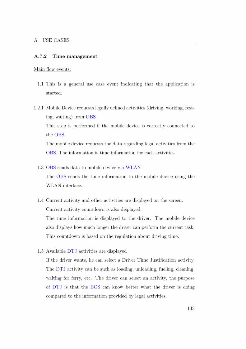
A USE CASES
A.7.2 Time management
Main flow events:
1.1 This is a general use case event indicating that the application is
started.
1.2.1 Mobile Device requests legally defined activities (driving, working, rest-
ing, waiting) from OBS
This step is performed if the mobile device is correctly connected to
the OBS.
The mobile device requests the data regarding legal activities from the
OBS. The information is time information for each activities.
1.3 OBS sends data to mobile device via WLAN
The OBS sends the time information to the mobile device using the
WLAN interface.
1.4 Current activity and other activities are displayed on the screen.
Current activity countdown is also displayed.
The time information is displayed to the driver. The mobile device
also displays how much longer the driver can perform the current task.
This countdown is based on the regulation about driving time.
1.5 Available DTJ activities are displayed
If the driver wants, he can select a Driver Time Justification activity.
The DTJ activity can be such as loading, unloading, fueling, cleaning,
waiting for ferry, etc. The driver can select an activity, the purpose
of DTJ is that the BOS can know better what the driver is doing
compared to the information provided by legal activities.
143

A USE CASES
1.6 New activity is sent to BOS
The new activity is sent to the BOS. Two connection types are possible
first one is to connect to back office via OBS (See: Send data to back
office via OBS). Second one is to connect to the BOS via mobile device
directly (See: Send data to back office via mobile device).
Alternative flow events:
1.2.2 Mobile Device attempts to connect to OBS (See: A.1.1)
In case there is no connection between a mobile device and OBS, alter-
native use case is performed (See: A.1.1).
144

A USE CASES
Figure 53: Coaching based on other drivers feedback
145

B OBS AND MOBILE DEVICE
B OBS and mobile device
Figure 54: OBS and mobile
146