Wireless Communications and Networksmedard/6.02s/6.02sday5.pdf•European GSM (groupe special...
123
MIT Wireless Communications and Networks Muriel Medard
Transcript of Wireless Communications and Networksmedard/6.02s/6.02sday5.pdf•European GSM (groupe special...
1MIT
Wireless Communications and Networks
Muriel Medard
2MIT
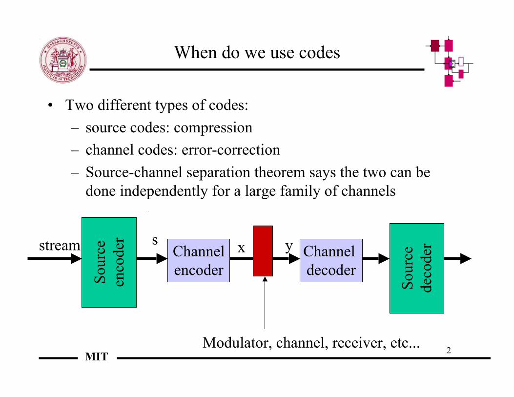
When do we use codes
• Two different types of codes:– source codes: compression– channel codes: error-correction– Source-channel separation theorem says the two can be
done independently for a large family of channels
Sour
ceen
code
r
Channelencoder
Channel decoder
stream
Modulator, channel, receiver, etc...
Sour
cede
code
rs x y

3MIT
Overview
• The physical layer• Wireless telephony:
– FDMA– TDMA– CDMA– UWB– 3G
• Wireless networking:– 802.11– Bluetooth
• Ad hoc networks
4MIT
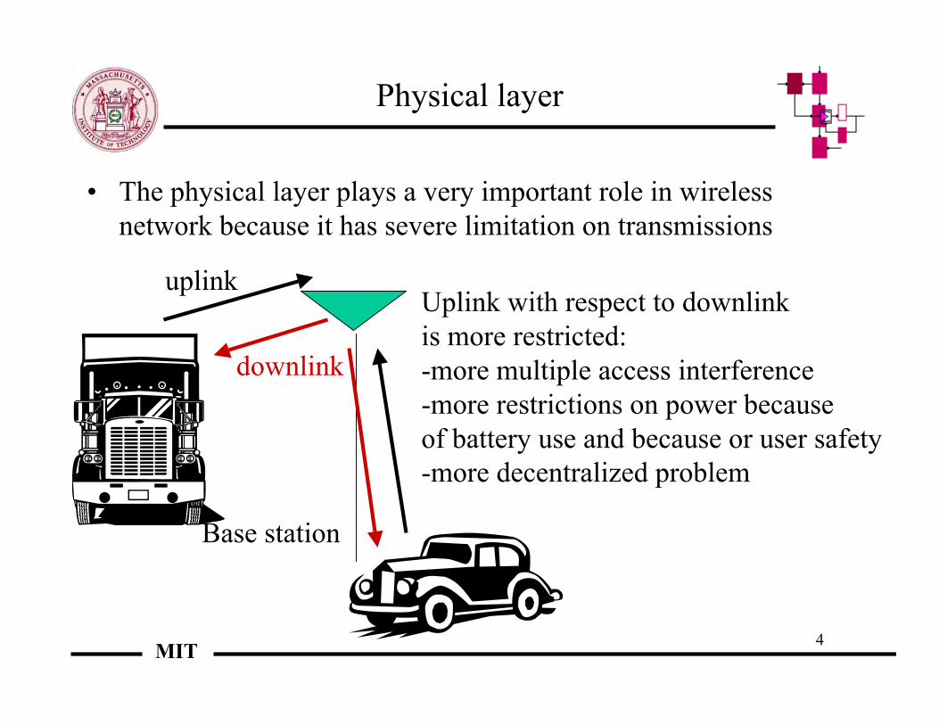
Physical layer
• The physical layer plays a very important role in wirelessnetwork because it has severe limitation on transmissions
Uplink with respect to downlink is more restricted:-more multiple access interference-more restrictions on power because of battery use and because or user safety-more decentralized problem
uplink
downlink
Base station

5MIT
The “cellular” system
The area of coverage ofDifferent base stations islogically a tessellation ofthe space
When a user is better servedBy a different base station,hand-off occurs
In reality, cell coverage is extremely uneven and irregular:
There are dead spots and areasof overlap
Handoff
Inter-cellinterference
Intra-cellinterference

6MIT
Antennas
• Base stations are generally antennas on towers or on top ofbuildings, with heavy tendency towards co-location, as thereal estate is generally owned by a few companies
• Antennas can have directionality, giving sectors of the cells
• Sectors reduce interference, but also pose coverage issues
Antenna lobes

7MIT
Use of multiple antennas
• Multiple antennas can be used in two ways:– In an adaptive fashion to cancel out interference
– In a static fashion to “gather” more of the signal: optimalways of combining the outputs rely on maximumlikelihood detection

8MIT
MIMO systems
• High SNR case: capacity goes with log(SNR) and min oftransmit and receive antennas
• Use of space-time-codes, Alamouti schemes• Very sensitive to changes in channel and uncertainty in
receive channel• Low SNR case: antennas just help to gather energy, capacity
depends only SNR and number of receive antennas\• Use of impulsive transmission schemes to achieve capacity or
near capacity

9MIT
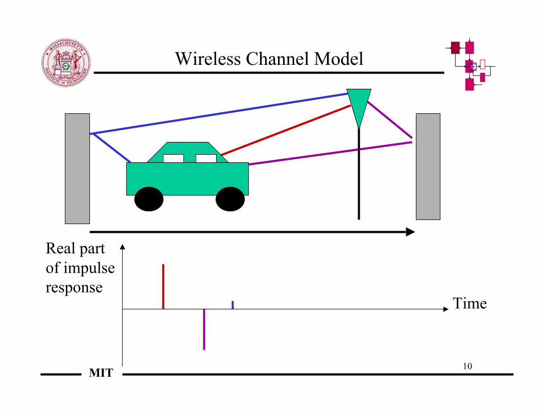
Wireless Channel Model
Real partof impulseresponse
Time
10MIT
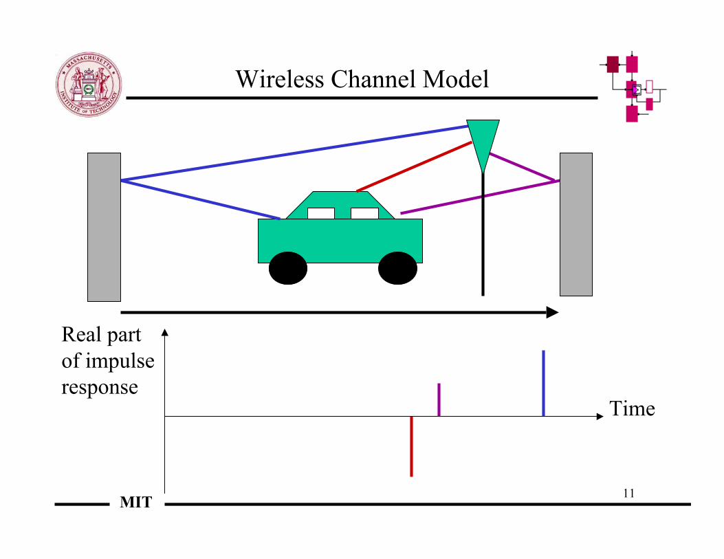
Wireless Channel Model
Real partof impulseresponse
Time
11MIT
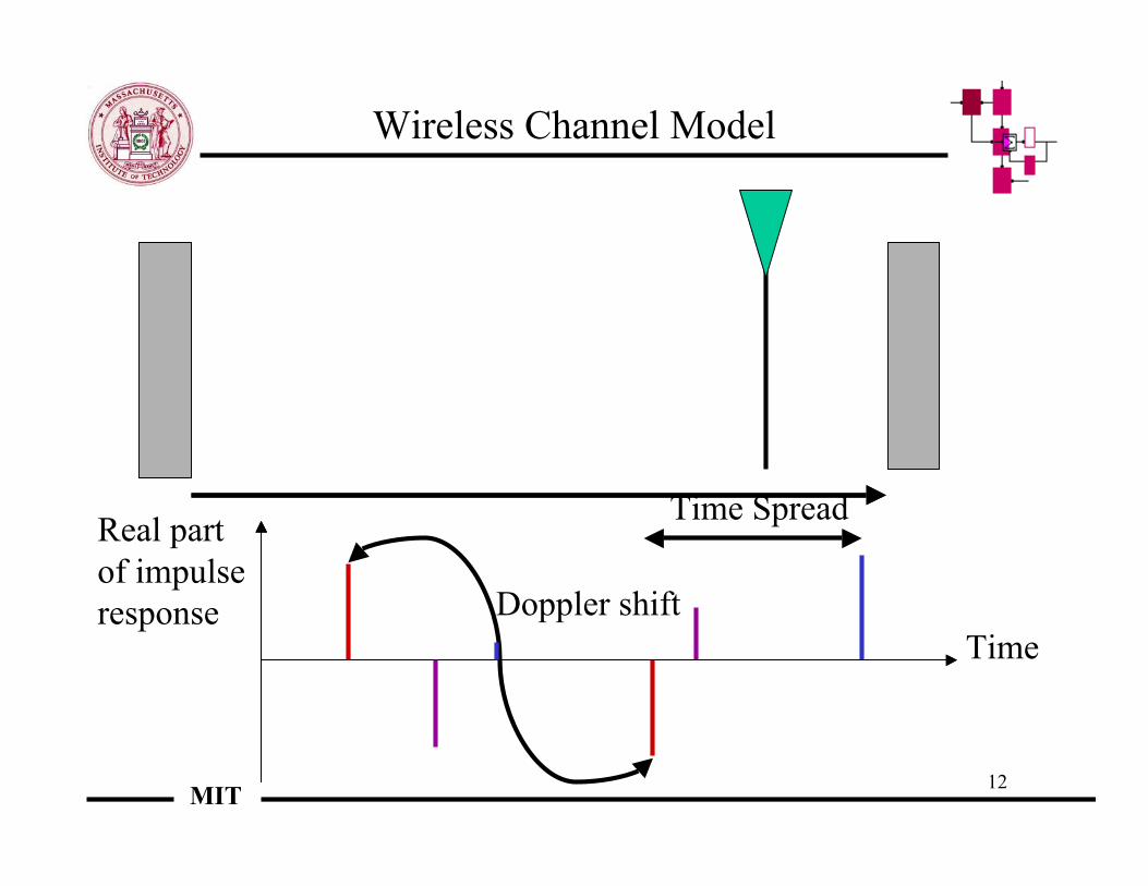
Wireless Channel Model
Real partof impulseresponse
Time
12MIT
Time Spread
Doppler shift
Wireless Channel Model
Real partof impulseresponse
Time
13MIT
Variations in time and frequency
• The channel roughly changes across time and frequency• In time, the time for change is roughly given by Tc, the
coherence time• The coherence time is generally taken to be the inverse of the
Doppler spread, which is proportional to the speed of themobile with respect to the obstacle and to the carrier frequency
• In frequency, the bandwidth for change is roughly given by Fc,the coherence bandwidth
• The coherence bandwidth is generally taken to the inverse ofthe time spread
• Most of the channels for wireless applications are of theunderspread type, which means that TcFc >> 1

14MIT
Implications of variations
• Variations occur and lead to fades• It is difficult to transmit during fades in time or in frequency• Therefore we try to achieve “diversity” in time and in
frequency• Diversity in frequency may be difficult to achieve because of
regulatory issues around spectrum• Diversity in time can be achieved but at the expense of delay
– use of interleaving to make the channel look memoryless
a b c d e f
a’ b’ c’ d’ e’ f’a a’ b b’ c c’ d d’
interleaving
good bad good
15MIT
How to adapt to the fades
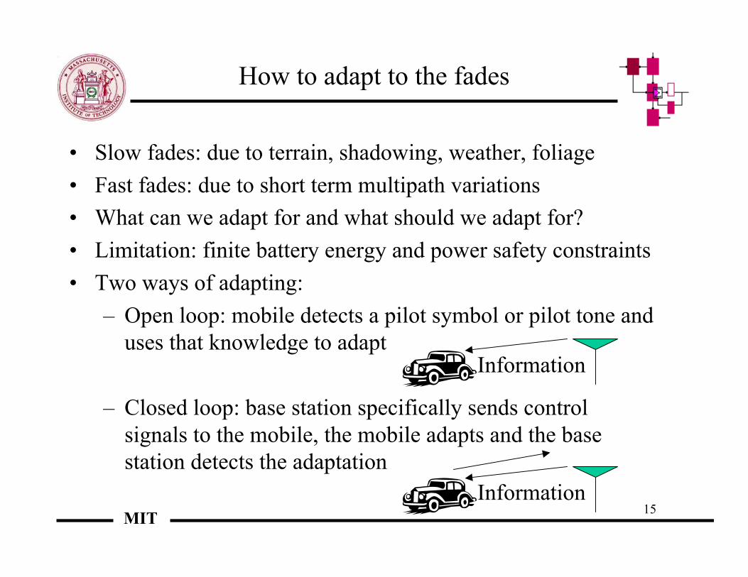
• Slow fades: due to terrain, shadowing, weather, foliage• Fast fades: due to short term multipath variations• What can we adapt for and what should we adapt for?• Limitation: finite battery energy and power safety constraints• Two ways of adapting:
– Open loop: mobile detects a pilot symbol or pilot tone anduses that knowledge to adapt
– Closed loop: base station specifically sends controlsignals to the mobile, the mobile adapts and the basestation detects the adaptation
Information
Information

16MIT
Adaptation and multiple access
• The near-far effect:
• In the case of open loop control, a mobile cannot make up formultiple access effects such as the near-far effect
• In the case of closed loop control, the users that are far canincrease their power, while the users that are far away candecrease their power
• Can we use power control to make up for fast fades? Tc isabout 1/100 s, so would easily require 1000 bits/s
The car closest to the base station overpowers the other car

17MIT
Receivers
• The receiver must take into account the instantaneous effect of thechannel
• Rake receiver is a means of taking into account the maincomponents of the channel
• Channel tap: sample of the channel• The Rake receiver finds the main non-zero taps (fingers)• Note: phase is needed to get information beyond the amplitude
Channel description
Rake receiver
Estimation/detection
18MIT
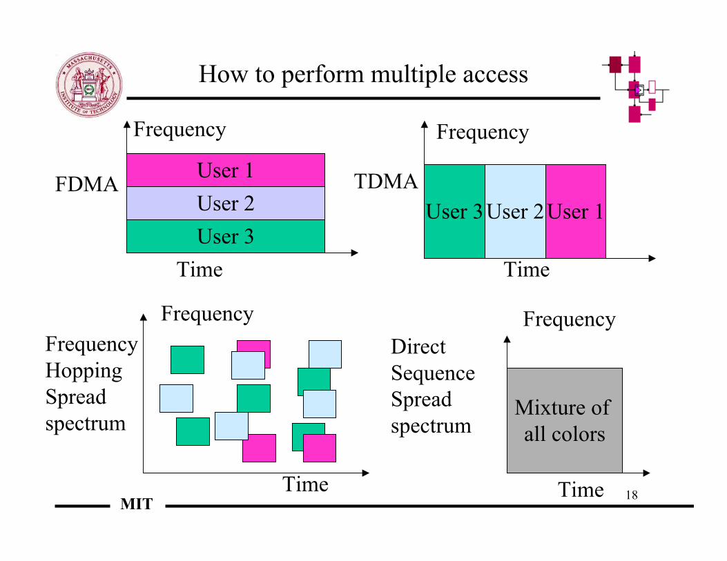
How to perform multiple access
User 3User 2
Time
Frequency
User 1
Time
Frequency
User 3User 2User 1FDMA TDMA
Frequency
Time
FrequencyHoppingSpreadspectrum
Mixture of all colors
Time
FrequencyDirect SequenceSpreadspectrum

19MIT
Channels in FDMA
• Channels in each cell• Each user in a cell is given an uplink channel and a downlink channel• AMPS: 30 kHz wide• 1993 old AMPS and NAMPS => IS-91• Uplink
• Dowlink
• A channels (channels 1-> 333) competitive provider• B channels (channels 334 ->666) -> wireline carrier
A’’ A B A’ B’
824 825 835 845 846.5 849 MHz
A’’ A B A’ B’
869 870 880 890 891.5 894 MHz
20MIT
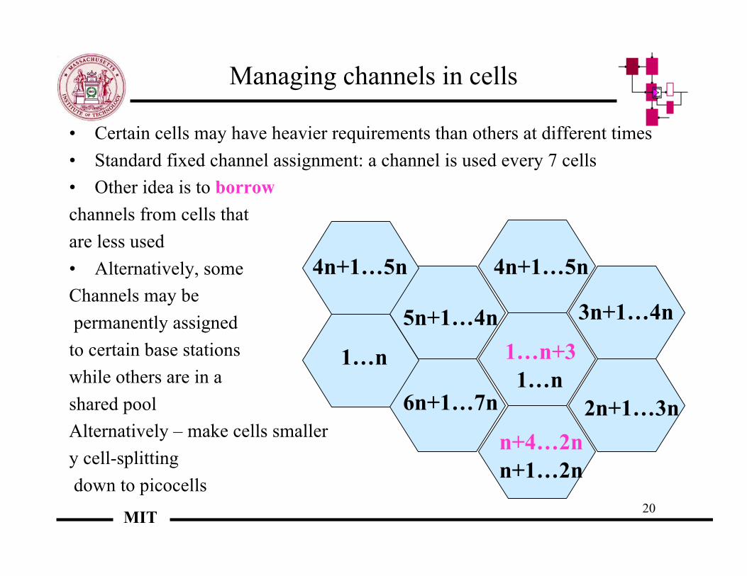
Managing channels in cells
• Certain cells may have heavier requirements than others at different times• Standard fixed channel assignment: a channel is used every 7 cells• Other idea is to borrowchannels from cells thatare less used• Alternatively, someChannels may be permanently assignedto certain base stationswhile others are in ashared poolAlternatively – make cells smallery cell-splitting down to picocells
1…n
n+1…2n
2n+1…3n
3n+1…4n
4n+1…5n
5n+1…4n
6n+1…7n
1…n
4n+1…5n
1…n+3
n+4…2n
21MIT
TDMA
• European GSM (groupe special mobile), IS-54 (US standard), JDC(Japan)
• GSM standardization effort started in 1987, Phase 2 ended in 1995• Divide a little in frequency, a lot in time• GSM:
– Eight channels per carrier with a gross data rate of 22.8 kbps (bitrate of 13 kbps)
– Frame is 4.6 ms and time slots are 0.575 ms for transmissionand reception
– 200 kHz channel spacing– Gaussian minimum shift keying (GMSK)

22MIT
TDMA
Pre-amble Slot 1 Slot 2 Slot 2 Slot 3 … Slot n Pre-
amble Slot 1
One frame
Pre=amble User 1 User 2
…User p Guard
time
23MIT
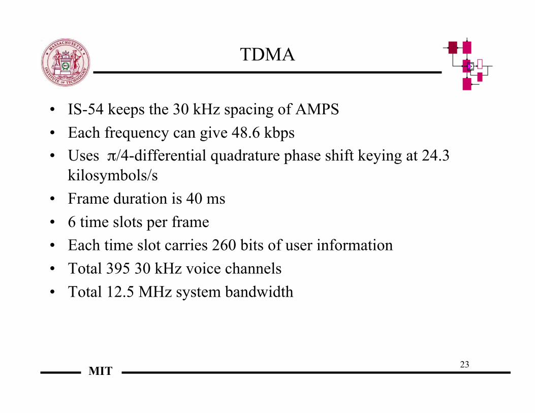
TDMA
• IS-54 keeps the 30 kHz spacing of AMPS• Each frequency can give 48.6 kbps• Uses π/4-differential quadrature phase shift keying at 24.3
kilosymbols/s• Frame duration is 40 ms• 6 time slots per frame• Each time slot carries 260 bits of user information• Total 395 30 kHz voice channels• Total 12.5 MHz system bandwidth

24MIT
CDMA
• Code division multiple access• Roots are in military applications:
– Anti-jam– Low-probability of intercept
• Frequency hop:– Slow: hop every few bits– Fast: hop every bit or faster– Relatively expensive because of tuning
• Direct sequence:– Use a spreading sequence to allow al users to share the
bandwidth at all times

25MIT
DS-CDMA
Data
time
W/2-W/2 Ws/2-Ws/2
spreading
time
Spreading sequence:chips
Ws > W
Spreading gain = chip rate/data rate

26MIT
IS-95
• Chip rate 1.2288 Mcps• Modulation is QPSK on forward. OQPSK on rverse• Filtered bandwidth in uplink or downlink is 1.23 MHz• 63 Walsh codes per link for forward• Convolutional coding with Viterbi decoding• Interleaving with 20 ms span• Main mode is 9600 bps (also available as 14,400 bps)• Available in the 90 MHz range and the PCS 2 GHz range• Reverse and forward links are separated by 45 MHz in the
former and 80 MHz in the latter

27MIT
CDMA2000
• 3-G system, generated in accordance with the recommendations ofthe International Mobile Telecommunications (IMT)-2000 of theITU (International Telecommunications Union)
• Main features:– Channel sizes of 1,3 , 6, 9 and 12 1.25 MHz– Advanced antenna technology support– Greater possible cell sites, up to megacells (>35 km in radius),
down to indoor.indoor picocells (<50m)– Allows voice services– End-user data services, packet data service node (PDSN) to
support Intenet/intranet data connectivity• Corresponding Universal wireless communications (UWC) is IS-
136
28MIT
Third generation
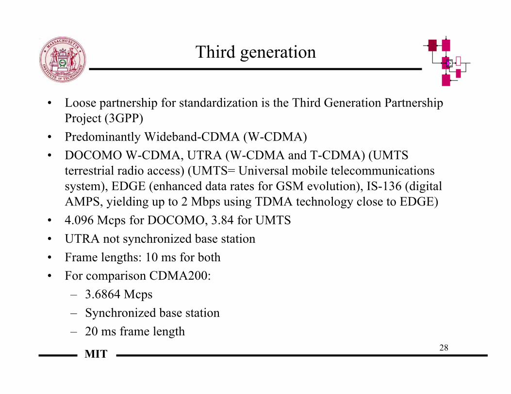
• Loose partnership for standardization is the Third Generation PartnershipProject (3GPP)
• Predominantly Wideband-CDMA (W-CDMA)• DOCOMO W-CDMA, UTRA (W-CDMA and T-CDMA) (UMTS
terrestrial radio access) (UMTS= Universal mobile telecommunicationssystem), EDGE (enhanced data rates for GSM evolution), IS-136 (digitalAMPS, yielding up to 2 Mbps using TDMA technology close to EDGE)
• 4.096 Mcps for DOCOMO, 3.84 for UMTS• UTRA not synchronized base station• Frame lengths: 10 ms for both• For comparison CDMA200:
– 3.6864 Mcps– Synchronized base station– 20 ms frame length

29MIT
New services to core network connection
Evolved GSM core
GPRS IPcore
IS-41
WCDMA
TD-CDMA
EDGE
CDMA2000GPRS: GSM General Packet Radio Service EDGE: Enhanced Data Rates for GSM EvolutionIS-41: industry standard for inter-switch signaling that allows validation of wireless calls and call completion in out-of-area markets
30MIT
Performance comparison
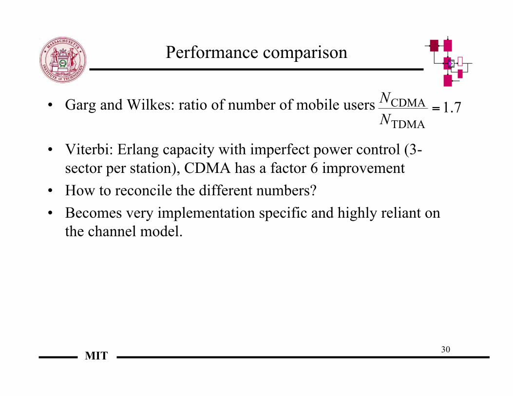
• Garg and Wilkes: ratio of number of mobile users
• Viterbi: Erlang capacity with imperfect power control (3-sector per station), CDMA has a factor 6 improvement
• How to reconcile the different numbers?• Becomes very implementation specific and highly reliant on
the channel model.
7.1
TDMA
CDMA =N
N
31MIT
Multiple access
R1
R2
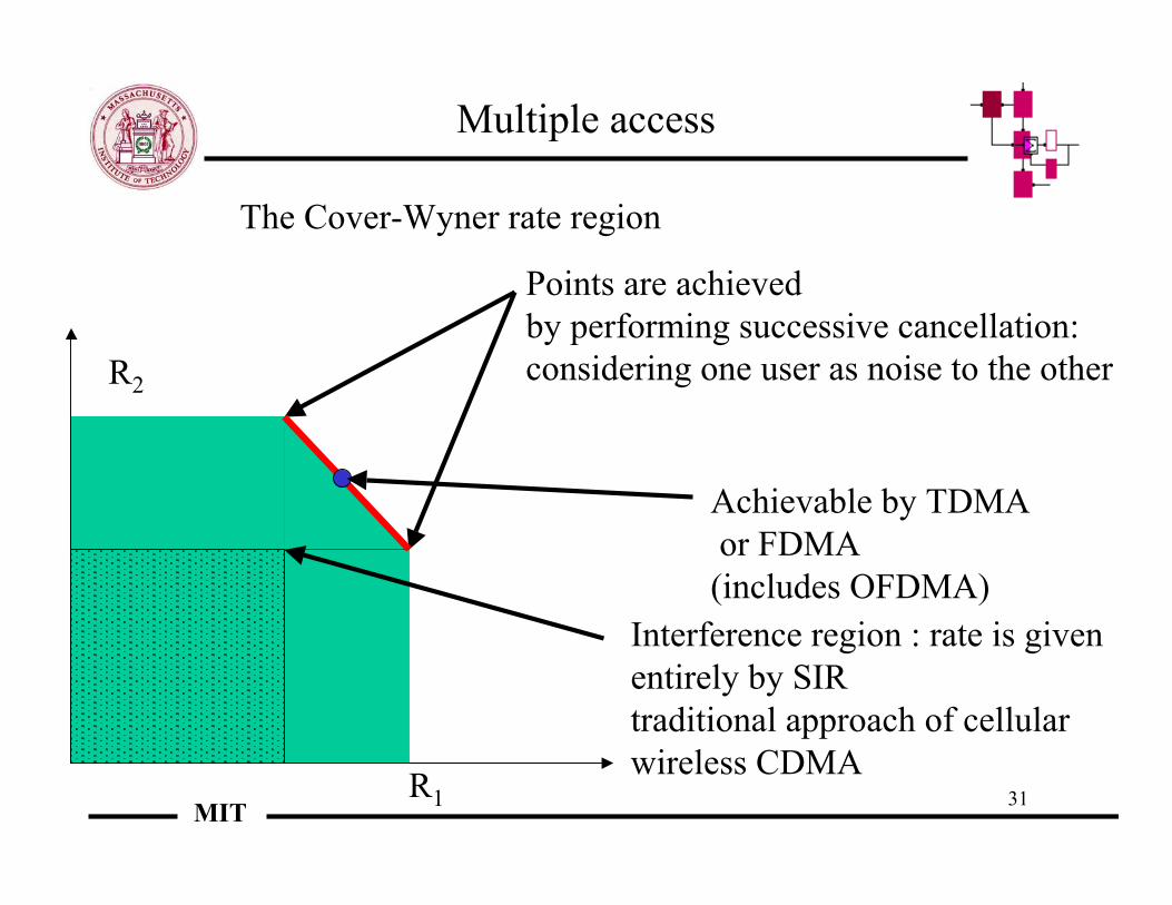
Points are achievedby performing successive cancellation:considering one user as noise to the other
The Cover-Wyner rate region
Interference region : rate is given entirely by SIRtraditional approach of cellularwireless CDMA
Achievable by TDMA or FDMA (includes OFDMA)

32MIT
High SNR Case
In the case of high SNR, system is quasi-optimal if runas a TDMA system
R1
R2
TDMA curve closely approximates maximum sum rate
Interference region is very suboptimal

33MIT
Low SNR case - Interference
R1
R2
Corner of interference region is close to maximum sum rate
Base station •The users compete for SIR atthe base station•The traditional cellularapproach is a max-minapproach based on explicitcommands using closed-loopcontrol•No concept of priority,whether permanent or inresponse to a rapid change ofcircumstances
34MIT
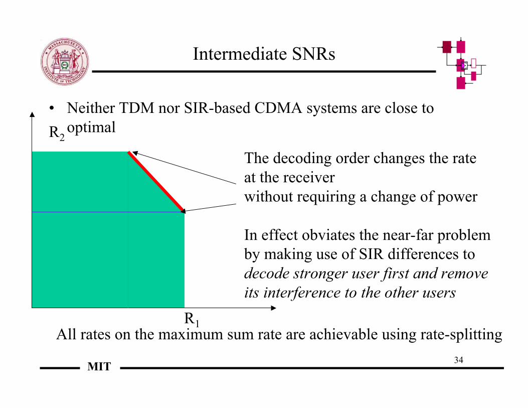
Intermediate SNRs
• Neither TDM nor SIR-based CDMA systems are close tooptimal
R1
R2
The decoding order changes the rateat the receiverwithout requiring a change of power
In effect obviates the near-far problem by making use of SIR differences to decode stronger user first and removeits interference to the other users
All rates on the maximum sum rate are achievable using rate-splitting

35MIT
Overview of UWB
• Wireless communications over broad band have beenevolving rapidly
• Quest: uncoordinated, cheap access to large amounts ofbandwidth for many users
• What do theoretical limits tell us about how possible this is?• Topics:
– Effectiveness of different spreading techniques - CDMA,FH, PPM, flash signaling
– When happens when we are not bandwidth limited?– Can we find simple schemes that successfully
approximate the infinite bandwidth results?– Can we have uncoordinated multiple access?
36MIT
Spreading
• DS-CDMA (direct sequence code division multiple access)has gained considerable commercial importance
• Spread in frequency by transforming bits into a series of chips• Every user appears as noise to all other users, good LPI• Why not simply extend this to higher bandwidths?• Does not scale when channel decorrelates in time and
frequency (Medard and Gallager, 1997, 2002, Telatar and Tse1999, Hajek and Subramanian, 1999, 2002)
• Intuitive justification - cannot track the channel well enough tomake reliable decisions because there is not enough energy inany portion of the spectrum

37MIT
Pulse-position modulation (PPM)
• Spread-spectrum multiple-access wireless system• Time-hopping baseband signal comprised of very short pulses -
occupies frequency band from near-DC to several GHz,• Low power-spectral density• Interference to other narrow-band systems should be low
(although very poor from the point of view of peak interference)• Appears to be sub-optimal from the point of view of
approaching capacity - it is limited theoretically by the timespread, so may not be useful for very wide bands
• Not very LPI

38MIT
Frequency hopping
• Robust to fades by changing frequencies• Does not suffer from channel tracking issues of DS-CDMA
because there is enough energy transmitted in a single portionof the spectrum to identify the channel
• Not generally used in commercial systems, except as someextra diversity added onto other systems
• Somewhat LPI

39MIT
What if we had unlimited bandwidth?
• Capacity of infinite-bandwidth multipath fading channel isequal to the capacity of the infinite-bandwidth channel withnoise only
• Capacity can be achieved using frequency-shift keying withnon-coherent detection by transmitting at a low duty cycle -``peaky'' or flash signaling (looks similar to FH)
• How does the probability of error decay to zero as bandwidthapproaches infinity for rates under capacity?
• Very slowly if we want to approach capacity (bandwidthmust grow rapidly to achieve low probability of error if weare close to capacity)
• Other drawback- huge peak energy

40MIT
Can we approach the infinite bandwidth limitwith finite bandwidth?
• Use FSK that is somewhat impulsive and also use it over morethan a single tone at a time
• Code over the tones that are used, rather than a single tone - thusallowing a reduction in peak energy
• Gets close to capacity for large bandwidths where DS-CDMA orPPM may no longer be effective
• Gracefully goes from energy-limited to bandwidth-limited regime• Joint work with Cheng Luo and Lizhong Zheng

41MIT
Capacity vs. bandwidth
10M 100M 1G 10G 100G 1T 10T
100
1 ,000
approx im ate ly 1 .9 dB
approx im ate ly 1 .9 dB
capac ity for P /2N0=250
L im ited energy bound when P /2N0=250
capac ity for P /2N0=2500
L im ited energy bound when P /2N0=2500
Capacit
y(nat/sec)
Bandw id th F (Hz )
Ts= 10 µsTd= 1 µs

42MIT
Capacity vs. M = number of coherence bands
10 100
10
100
L im ited ene rgy b ound fo r P/2N0=40
the cap ac ity o f 2 -tone FSK
the cap ac ity o f FSK
L im ited bandw id th b ound fo r FSK
L im ited bandw id th b ound fo r 2 -tone FSK
Capacit
y(nat/sec)
M
Ts= 0.1 sTd= 1 µsP/2N0= 40

43MIT
Wireless data and networks
• Wireless LANs (WLANs):• Main standards efforts:
– IEEE 802.11– High-Performance Radio Local Area Network (HIPERLAN)– Wireless Information Networks Forum (WINForum)– IEEE 802.16
• General issues: packetized access for wireless• How do interleaving and higher probability of packet loss affect
buffering, window sizes and end-to-end protocols
44MIT
802.11
• MAC for peer-to-peer and peer-to-centralized communicationsusing DSSS and FHSS for radio and infrared
• 2.4-2.4835 band, over more than 80 MHz• Allows for 1 Mbps or 2 Mbps• Uses BPSK or QPSK modulation for for DSSS and Gaussian
FSK for FHSS• For DSSS, 5 overlapping bands of 26 MHz each• For FHSS, 79 sub-bands, each 1 MHz wide, and 3 patterns of
22 hop• CSMA/CA• Maximum power of 1 W

45MIT
More wireless networks
• HIPERLAN:– emanates from ETSI (European Telecommunications
Standards Institute)through technical subcommittee RES 10– Two bands 5.12-5.30 GHz and 17.1 –17.3 GHz– Rates of 500-1000 Mbps per user for total of about 20 Mbps
• WINforum:– For WLAN and wireless private branch exchange– Short bursts, quick release of medium– Asynchronous bands of 50 KHz to 10 MHz, isochronous bands
of 1.25 MHz

46MIT
Bluetooth
• Born in 1994, when Ericsson looked for alternatives for interfaces betweenmobile phones and accessories
• The name: Harald Blatand - Danish King who united Denmark and Norway inthe Xth century
• Since 1998, Bluetooth Special Interest Group has spearheaded the specification(First one released in July 1999)
• Low-cost applications – about $ 5 each• Ranges of up to 10 m, 20 m and 100 m• Need to have networking ability as well as point-to-point• Need to be able to carry voice and data• Low power requirements:
– Class 1 100 mW (20 dBm)– Class 2 2.5 mW (4 dBm)– Class 3 1 mW (0dBm)

47MIT
Frequency hopping
• 2.4 GHz operation: Industrial, Scientific and Medical (ISM) band –a very polluted band
• The AJ properties of spread-spectrum are well suited to thisenvironment
• 1 MHz-spaced channels, each signaling at 1 Mbaud per second,using GFSK (1Mb/s)
• Frequency hops between packets• Slots are 635 microseconds and packets last 1, 3 or 5 slots

48MIT
Packets
• Two types of packets: SCO (synchronous Connection Oriented)for voice and ACL (Asynchronous Connectionless) for data
• ACL: has 72 bit access code, 54-bit packet header and 16-bitCRC
• Largest packet size is 5 lots (DH5) with 2712 bits of data, restoverhead
• Largest full duplex data rate is using DH-5 packets in eachdirection – 433.9 kbps in each direction (for comparison, MP3 isabout 128 kb/s)
• SCO gives 64 kbps - same as GSM
49MIT
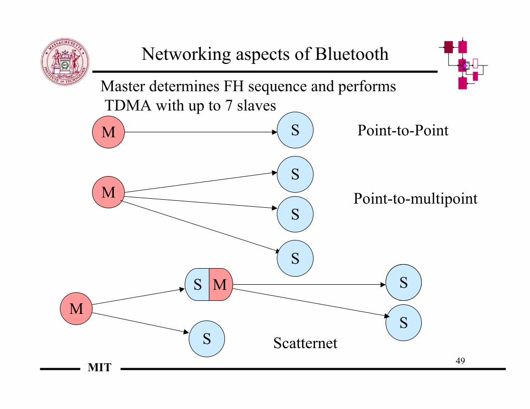
Networking aspects of Bluetooth
M S Point-to-Point
MS
S
S
Point-to-multipoint
MS
S
S
S
MS
Scatternet
Master determines FH sequence and performs TDMA with up to 7 slaves

50MIT
802.16
• Wireless MAN task group• Task group 1: looking at for Fixed Broadband Wireless
Access Systems for 10-66 GHz – 802.16• Task group 3 amends the above as MAC Modifications and
Additional Physical Layer for 2-11 GHz –802.16a• Task group 4 amends 802-16b Modifications and Additional
Physical Layer for License-Exempt Frequencies – AKA thewireless human (?!)
• Issues – as we go up in carrier frequency, propagationworsens, also underspread assumption begins to hold less
51MIT
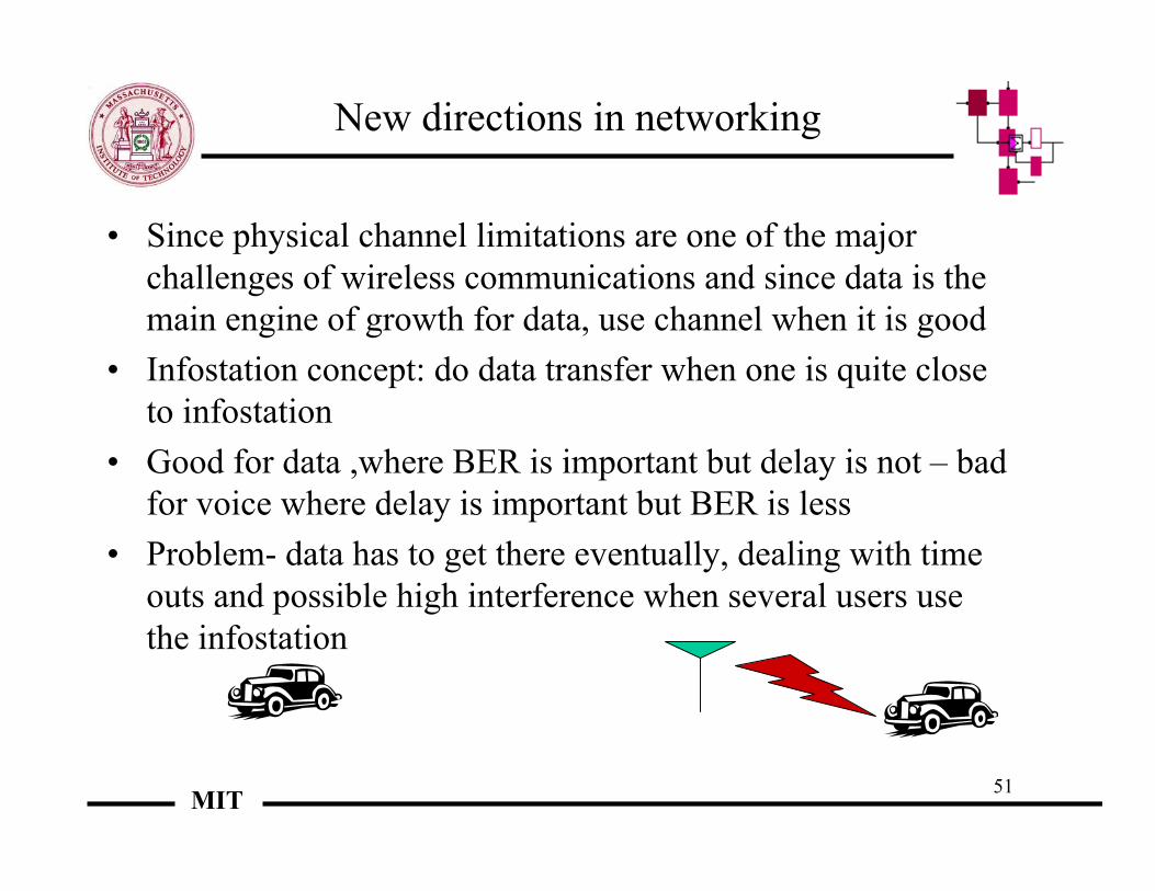
New directions in networking
• Since physical channel limitations are one of the majorchallenges of wireless communications and since data is themain engine of growth for data, use channel when it is good
• Infostation concept: do data transfer when one is quite closeto infostation
• Good for data ,where BER is important but delay is not – badfor voice where delay is important but BER is less
• Problem- data has to get there eventually, dealing with timeouts and possible high interference when several users usethe infostation
52MIT
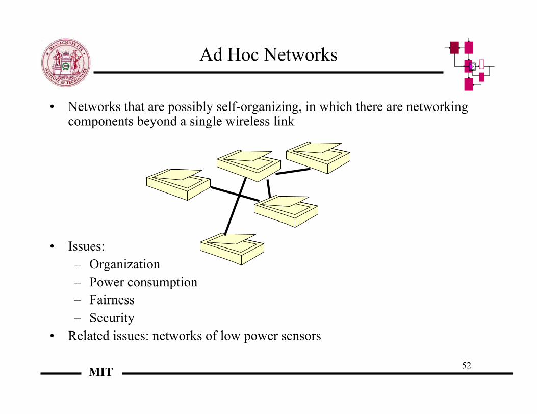
Ad Hoc Networks
• Networks that are possibly self-organizing, in which there are networkingcomponents beyond a single wireless link
• Issues:– Organization– Power consumption– Fairness– Security
• Related issues: networks of low power sensors
53MIT
Ad-hoc networks
• Scaling laws - Gupta and Kumar• θ(n) bit.m/s for certain types of networks if there is enough
receiver complexity• θ(√n) bit.m/s with reduced complexity, giving only θ(1/ √(n
logn)) bit.m/s for a node to a random other node• Mobility helps, by allowing transmission at propitious times -
Grossglauser and Tse : long-term throughout can be keptconstant in the face of a growing number of users, albeit atthe cost of extra delay
54MIT
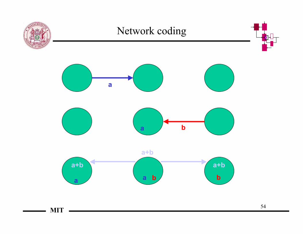
Network coding
a
a b
a b
a+b
a+b a+b
a b

55MIT
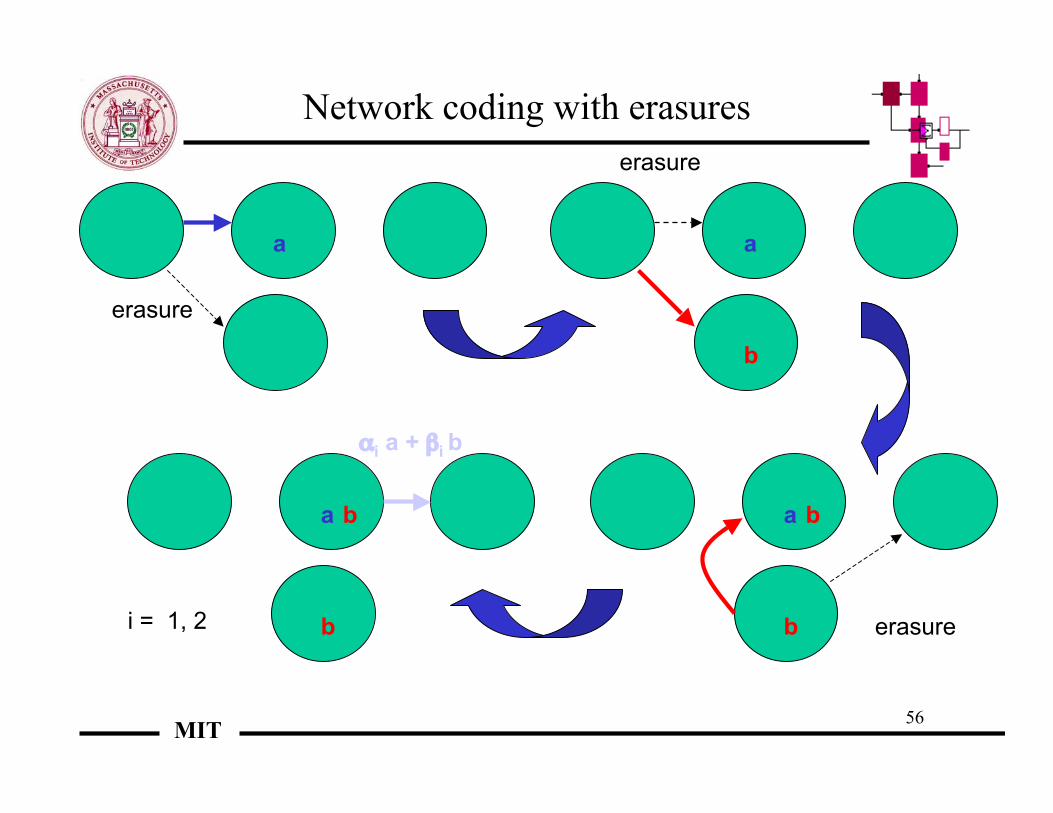
Networking coding in thepresence of impairments
• What occurs when transmissions are corrupted or missing?• Example: a is missing, so that a+b alone is received, which yields nonsense• When all received packets are relevant (multicast case), simply collect degrees of
freedom until a sufficient number has been accumulated• How does this concord with protocols, say TCP?
– TCP repeats information packet by packet until it is received – it is in effect avery constrained case of a length one (or a few) packet(s) repetition networkcode with no intermediate coding
– Hop-by-hop acknowledgement is a constrained length one packet repetitioncode with intermediate coding
• Network coding is a logical step in erasure reliability for networks
56MIT
Network coding with erasures
a
erasure
a
erasure
b
a
erasureb
ba
b
b
αi a + βi b
i = 1, 2

57MIT
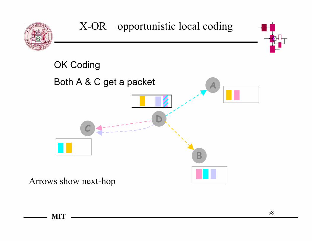
Arrows show next-hop
D
A
B
C
X-OR – opportunistic local coding
[Katabi et al. 05]
58MIT
X-OR – opportunistic local coding
Arrows show next-hop
D
A
B
C
OK Coding
Both A & C get a packet

59MIT
X-OR – opportunistic local coding
Arrows show next-hop
D
A
B
C
Best Coding
A, B, and C, each gets a packet
To XOR n packets, each next-hop should have then-1 packets encoded with the packet it wants

60MIT
0
200
400
600
800
1000
1200
1400
1600
1800
1 3 5 7 9 11 13 15 17 19 21
Number of flows in experiment
No Coding
Net. Throughput (KB/s)
Opportunistic network coding vs. traditional routing in 802-11
Our Scheme
[Katabi et al. 05]
61MIT
New areas in wireless
• Several active areas of research:– Ultra-wideband systems– Software-defined radios– Mobility management– Network coding

Laboratory for Information and Decision SystemsEytan Modiano
Slide 1
LIDS
Optical Networksand
Wavelength Division Multiplexing (WDM)
Eytan Modiano

Laboratory for Information and Decision SystemsEytan Modiano
Slide 2
LIDS
Outline
• Introduction– SONET– WDM
• All optical networks– LANs– WANs
• Hybrid optical-electronic networks– IP over WDM– Protection– Topology design
Laboratory for Information and Decision SystemsEytan Modiano
Slide 3
LIDS
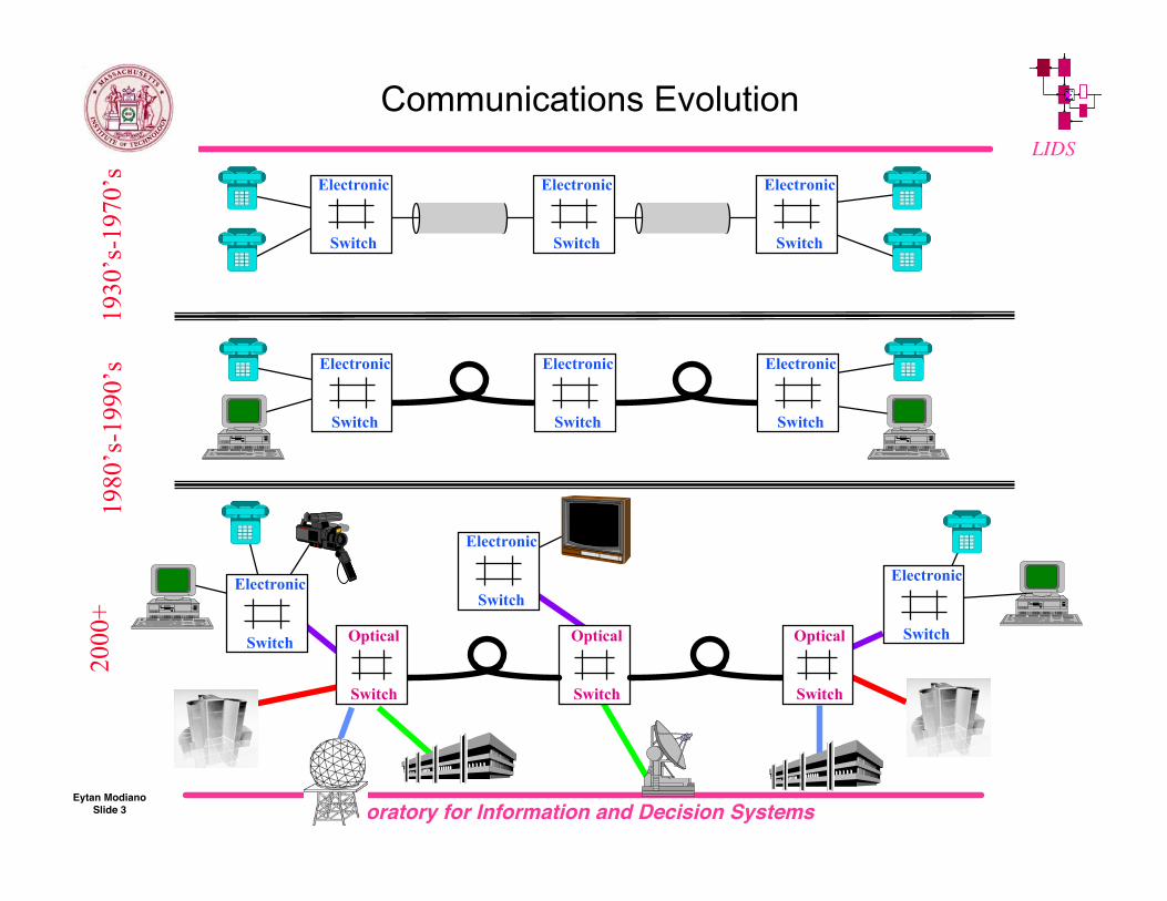
Communications Evolution19
80’s
-199
0’s
fiber fiber
Electronic
Switch
Electronic
Switch
Electronic
Switch
1930
’s-1
970’
s
Electronic
Switch
Electronic
Switch
Electronic
Switch
2000
+
fiber
Optical
Switch fiber
Optical
Switch
Optical
Switch
Electronic
Switch
Electronic
Switch
Electronic
Switch

Laboratory for Information and Decision SystemsEytan Modiano
Slide 4
LIDS
Synchronous Optical Network (SONET)
• Standard family of interfaces for optical fiber links– Line speeds
n x 51.84 Mbps n=1,3,12,48,192, 768
– TDMA frame structure 125 µsec frames
– Multiplexing Basic unit is 64 kbps circuit for digitized voice
– Protection schemes Ring topologies

Laboratory for Information and Decision SystemsEytan Modiano
Slide 5
LIDS
SONET Line Rates
FiberOpticSignal
OC Level
SynchronousTransport
SignalSTS Level
SynchronousTransport
ModeSTM Level
Line Rate
DS0(64 KBPS)
DS1(1.54 Mbps)
DS3(44.74 Mbps)
OC1 STS-1 51.84 Mbps 672 28 1
OC3 STS-3 STM-1 155.52 Mbps 2016 84 3
OC12 STS-12 STM-4 622.08 Mbps 8064 336 12
OC48 STS-48 STM-16 2488.320 Mbps 32256 1344 48
OC-192 STS-192 9953.280 Mbps 129024 5376 192
EquivalentChannels
1995
2000
BackboneSpeeds
STM-64
OC-768 STS-768 STM-256 39813.12 Mbps 516096 21504 768

Laboratory for Information and Decision SystemsEytan Modiano
Slide 6
LIDS
Multiplexing Frame Format
3 columns of transport overhead:
Section overhead
OH PAYLOAD OH PAYLOADOH PAYLOAD
9 rows
90 columns (87 columns of payload)
STS-1Synchronous
PayloadEnvelope
810 bytes x 8000 frame/sec x 8 bits = 51,840,000 bits
Path overhead Line overhead
Laboratory for Information and Decision SystemsEytan Modiano
Slide 7
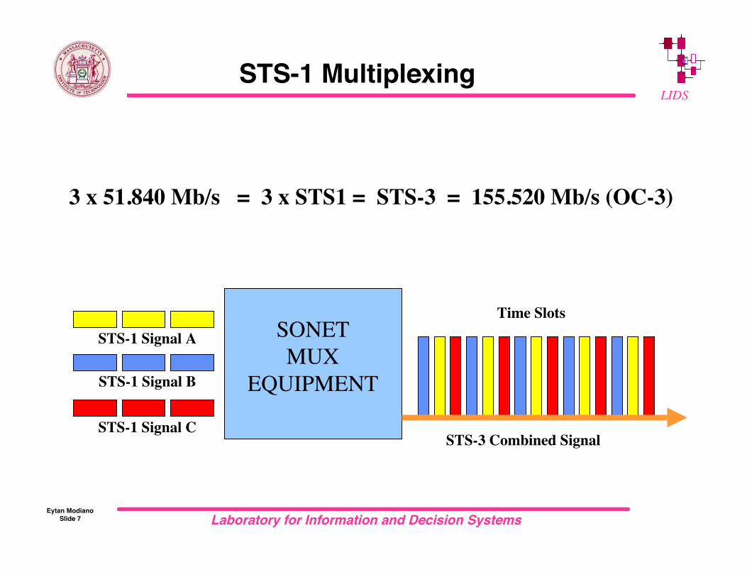
LIDSSTS-1 Multiplexing
STS-1 Signal A
STS-1 Signal B
STS-1 Signal CSTS-3 Combined Signal
SONETMUX
EQUIPMENT
3 x 51.840 Mb/s = 3 x STS1 = STS-3 = 155.520 Mb/s (OC-3)
Time Slots
Laboratory for Information and Decision SystemsEytan Modiano
Slide 8
LIDS
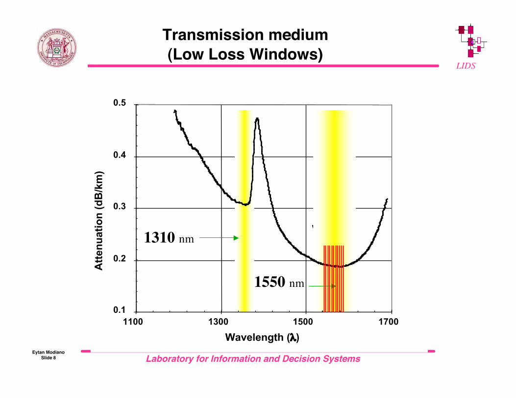
Transmission medium(Low Loss Windows)
0.1
0.2
0.3
0.4
0.5
1100 1300 1500 1700
Wavelength (λ)
1550window
Atte
nuat
ion
(dB
/km
)
1310 nm
1550 nm

Laboratory for Information and Decision SystemsEytan Modiano
Slide 9
LIDS
Network Elements and Topologies
Ring #1 Ring #2
DCS
Central Office
RingADM
ADM
ADM
Linear (pt-to-pt)
Work
Protect
• Add Drop Multiplexers (ADMS)– (De) multiplex lower rate
circuits into higher rate stream
• Digital Cross-connects (DCS)– Switch traffic streams
Laboratory for Information and Decision SystemsEytan Modiano
Slide 10
LIDS
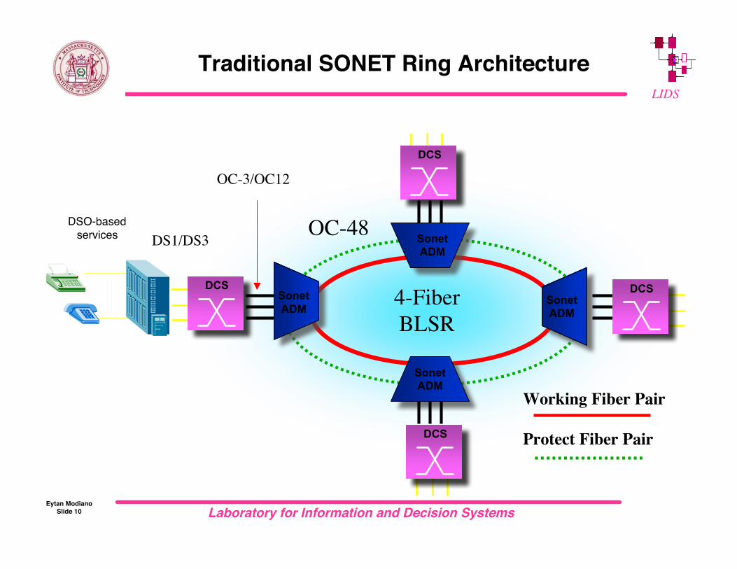
DSO-basedservices
Traditional SONET Ring Architecture
DCS
DCS
DCS
Working Fiber Pair
Protect Fiber Pair
SonetADM
SonetADM
SonetADM
SonetADM
OC-48
DCS
DS1/DS3
OC-3/OC12
4-FiberBLSR

Laboratory for Information and Decision SystemsEytan Modiano
Slide 11
LIDS
Link protection schemes
(Source) (Destination)
Working fiber
Protection
1+1Simultaneoustransmission
(Source) (Destination)
Working fiber
Protection
1:1Switchedrecovery
50 % bandwidth inefficiency

Laboratory for Information and Decision SystemsEytan Modiano
Slide 12
LIDSProtection Schemes: 1:n
1:n Protection Switching
(Source) (Destination)
Working fibers
Protection Fibers
...
123

Laboratory for Information and Decision SystemsEytan Modiano
Slide 13
LIDSPath vs. line protection
D1
S
D2
D1
S
D2
Path Protection Line Protection (Loopback)

Laboratory for Information and Decision SystemsEytan Modiano
Slide 14
LIDS
Protection Schemes: UPSR
Unidirectional/Path Switched Ring (UPSR)
Working
Rx
Rx
TxRx
Tx
1+1 protection60 ms restoration time
protection

Laboratory for Information and Decision SystemsEytan Modiano
Slide 15
LIDS
Protection Schemes: BLSR
Bidirectional/Line Switched Ring (BLSR)
Shortest path routing
Span and path protection
2 and 4 fibers
working
protection
Laboratory for Information and Decision SystemsEytan Modiano
Slide 16
LIDS
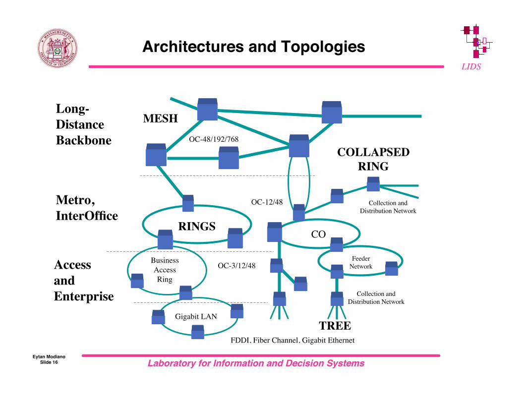
Collection andDistribution Network
CO
BusinessAccessRing
Collection andDistribution Network
Long-DistanceBackbone
Metro,InterOffice
AccessandEnterprise
Gigabit LAN
FeederNetwork
FDDI, Fiber Channel, Gigabit Ethernet
OC-3/12/48
OC-12/48
OC-48/192/768
Architectures and Topologies
MESH
COLLAPSEDRING
RINGS
TREE
Laboratory for Information and Decision SystemsEytan Modiano
Slide 17
LIDS
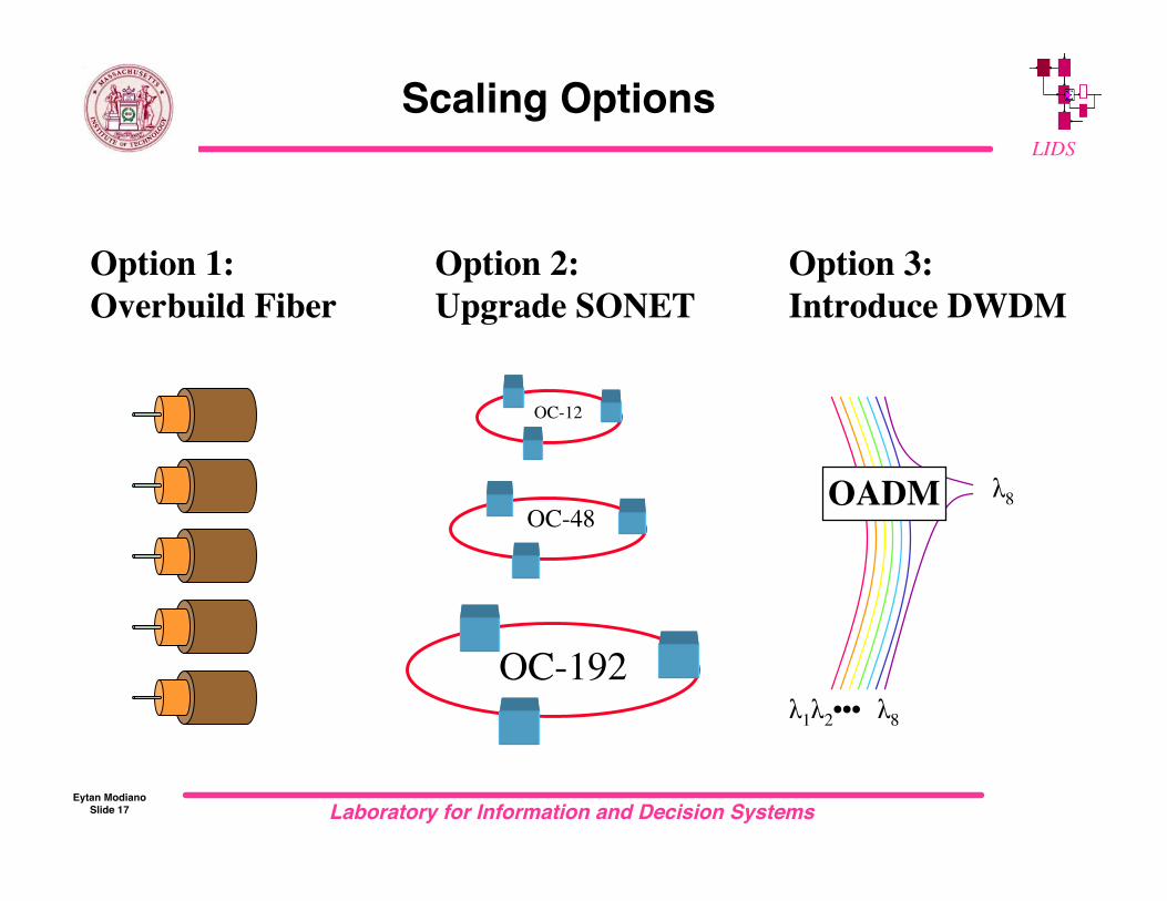
Scaling Options
Option 2:Upgrade SONET
Option 3:Introduce DWDM
λ1λ2
λ8
••• λ8
OADM
OC-12
OC-48
OC-192
Option 1:Overbuild Fiber
Laboratory for Information and Decision SystemsEytan Modiano
Slide 18
LIDS
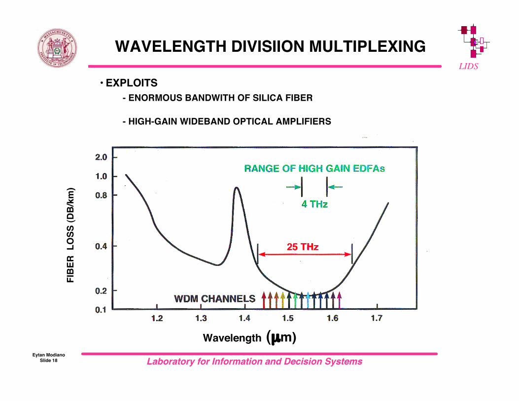
WAVELENGTH DIVISIION MULTIPLEXING
• EXPLOITS- ENORMOUS BANDWITH OF SILICA FIBER
- HIGH-GAIN WIDEBAND OPTICAL AMPLIFIERS
FIBE
R L
OSS
(DB/
km)
Wavelength (µm)
Laboratory for Information and Decision SystemsEytan Modiano
Slide 19
LIDS
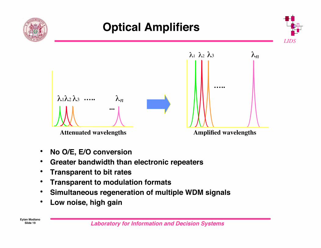
Optical Amplifiers
• No O/E, E/O conversion• Greater bandwidth than electronic repeaters• Transparent to bit rates• Transparent to modulation formats• Simultaneous regeneration of multiple WDM signals• Low noise, high gain
...λ1λ2 λ3 λn…..
Attenuated wavelengths
λn
…..
λ1 λ2 λ3
Amplified wavelengths
Laboratory for Information and Decision SystemsEytan Modiano
Slide 20
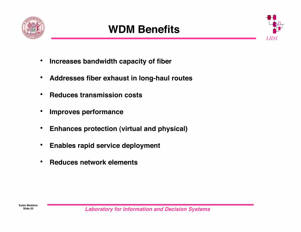
LIDSWDM Benefits
• Increases bandwidth capacity of fiber
• Addresses fiber exhaust in long-haul routes
• Reduces transmission costs
• Improves performance
• Enhances protection (virtual and physical)
• Enables rapid service deployment
• Reduces network elements

Laboratory for Information and Decision SystemsEytan Modiano
Slide 21
LIDS
SONET over WDM
1310nmrepeater
1310nmrepeater
1310nmrepeater
1310nmrepeater
Sonet
Sonet
Sonet
Sonet
Sonet
Sonet
Before
AfterSonet
Sonet
Sonet
Sonet
Sonet
Sonet
!1
M
!n
!1K!
n
!1
M
!n
EDFA
40 km
80 km

Laboratory for Information and Decision SystemsEytan Modiano
Slide 22
LIDS
All optical WDM networks
• Network elements– Broadcast star– Wavelength router– Frequency selective switch– Wavelength converters
• WDM LANs– Passive networks– Broadcast star based
• WDM WANs– Hierarchical architectures– Wavelength assignment– Wavelength conversion
Laboratory for Information and Decision SystemsEytan Modiano
Slide 23
LIDS
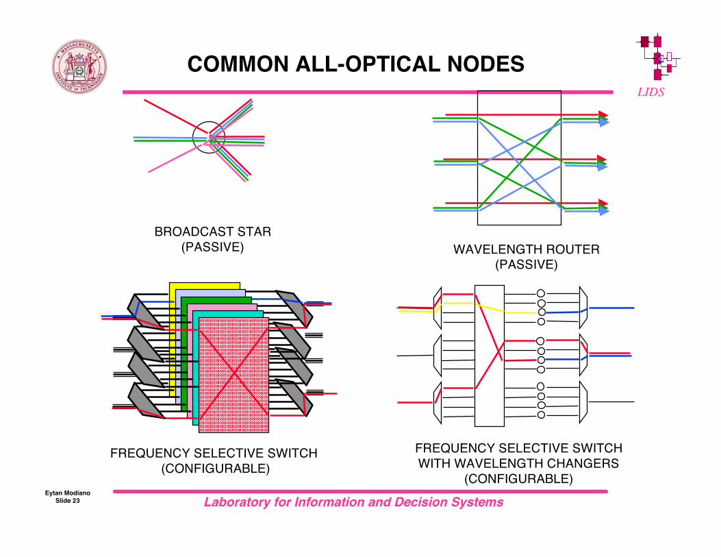
WAVELENGTH ROUTER(PASSIVE)
COMMON ALL-OPTICAL NODES
BROADCAST STAR(PASSIVE)
FREQUENCY SELECTIVE SWITCH (CONFIGURABLE)
FREQUENCY SELECTIVE SWITCHWITH WAVELENGTH CHANGERS
(CONFIGURABLE)

Laboratory for Information and Decision SystemsEytan Modiano
Slide 24
LIDS
Broadcast star (passive)
• Each output contains all inputs• High loss
– 3 db per stage– Log N stages
• No frequency reuse– Only one user per wavelength
• Cheap and simple• Support W connections
!
OT
OT
OT OT
OT
OT
combine split
3 db couplers
Laboratory for Information and Decision SystemsEytan Modiano
Slide 25
LIDS
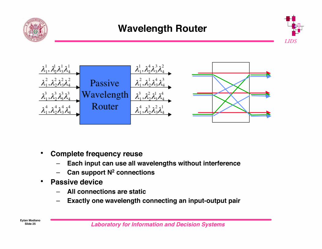
Wavelength Router
• Complete frequency reuse– Each input can use all wavelengths without interference– Can support N2 connections
• Passive device– All connections are static– Exactly one wavelength connecting an input-output pair

Laboratory for Information and Decision SystemsEytan Modiano
Slide 26
LIDS
Multiplexers and De-multiplexers
• Multiplexer– Single output of a router
• Demultiplexer– Single input to router
!1, !
2!3!4
!1
!2
!3
!4
!1, !
2!3!4
Demultiplexer multiplexer
!1
!2
!3
!4

Laboratory for Information and Decision SystemsEytan Modiano
Slide 27
LIDS
Optical Add/Drop Multiplexers (ADM)
• An ADM can be used to “drop” one or more wavelengths at a node– One input fiber and one output fiber plus local “drop” fibers– can be either static or configurable– Usually limited number of wavelengths– Loss proportional to number of wavelengths that can be dropped at a
node
Wavelength Multiplexer
~ ~
Wavelength Demultiplexer
λ1
λ2
λ3
λ4
λ4
λ1
λ2
λ3
λ4
λ4

Laboratory for Information and Decision SystemsEytan Modiano
Slide 28
LIDS
Frequency Selective Switch
• M input and M output fibers• Any wavelength can be switched from any input fiber to any
output fiber• Expensive device that offers a lot of configurability
– Switch times depend on implementation but are typically in the fewms range
•••
Demux Mux
!1!2K!
w
!1!2K!
w
!1!2K!
w
!1!2K!
w
!1!2K!
w
!1!2K!
w
!1
!2
!w
M
M x Mswitch
Laboratory for Information and Decision SystemsEytan Modiano
Slide 29
LIDS
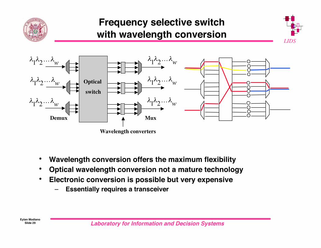
Frequency selective switchwith wavelength conversion
• Wavelength conversion offers the maximum flexibility• Optical wavelength conversion not a mature technology• Electronic conversion is possible but very expensive
– Essentially requires a transceiver
Optical
switch
Wavelength converters
Demux Mux
!1!2K!
w !1!2K!
w
!1!2K!
w
!1!2K!
w
!1!2K!
w
!1!2K!
w
Laboratory for Information and Decision SystemsEytan Modiano
Slide 30
LIDS
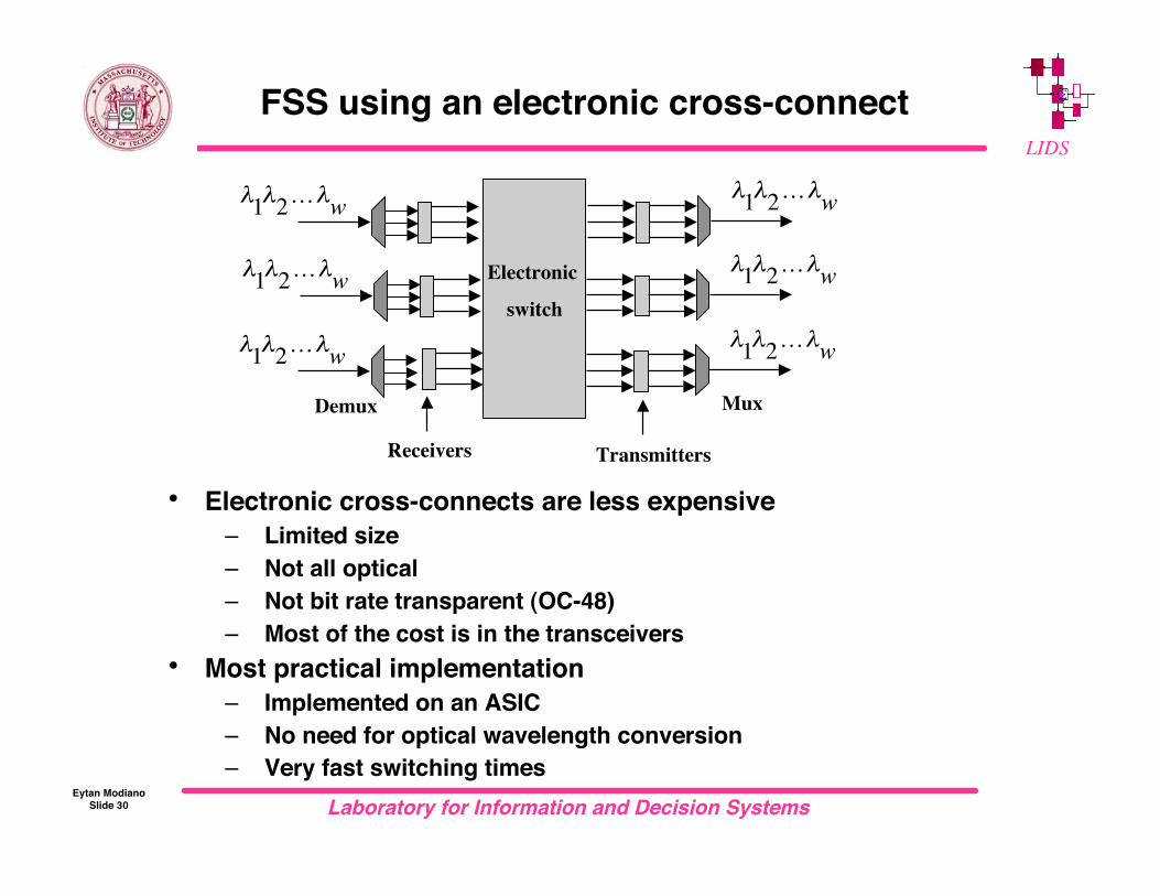
FSS using an electronic cross-connect
• Electronic cross-connects are less expensive– Limited size– Not all optical– Not bit rate transparent (OC-48)– Most of the cost is in the transceivers
• Most practical implementation– Implemented on an ASIC– No need for optical wavelength conversion– Very fast switching times
Demux
!1!2K!
w
Electronic
switch
Transmitters
Mux
!1!2K!
w
!1!2K!
w
!1!2K!
w
!1!2K!
w
!1!2K!
w
Receivers
Laboratory for Information and Decision SystemsEytan Modiano
Slide 31
LIDS
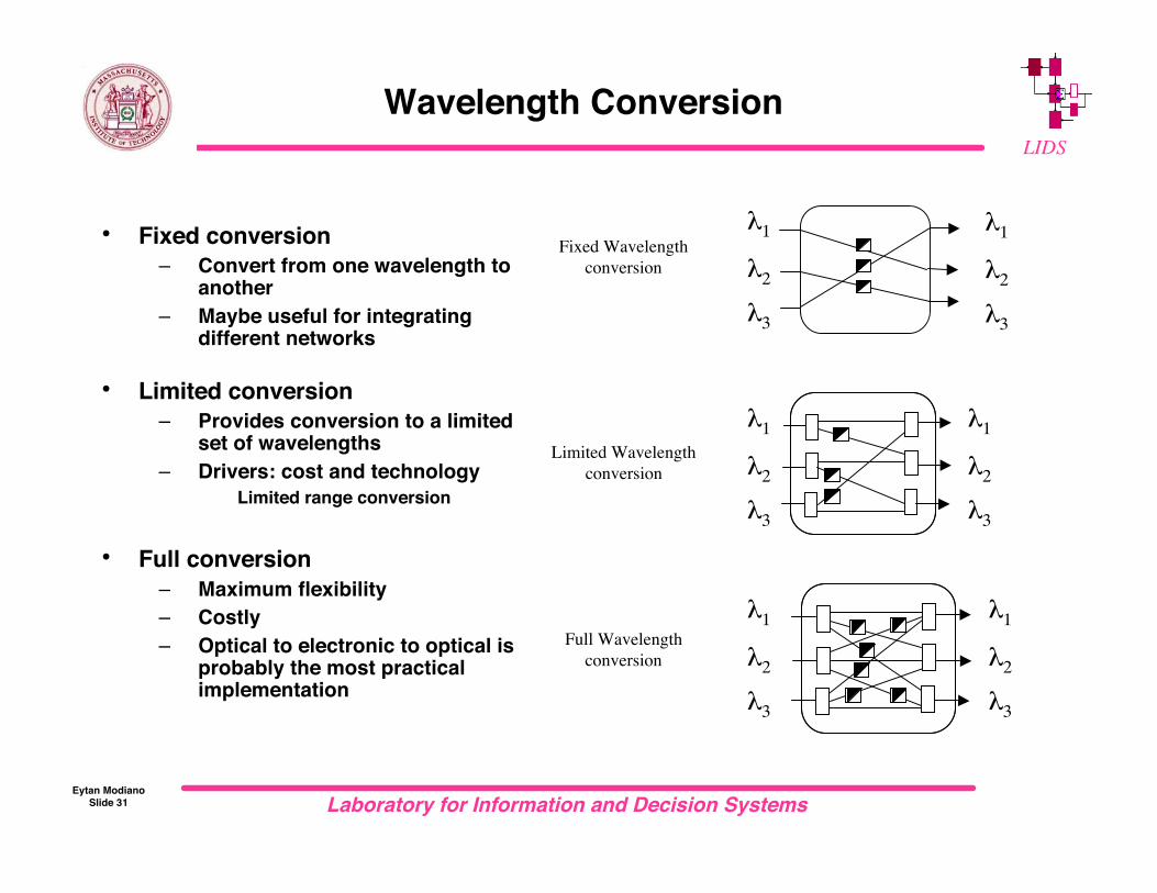
Wavelength Conversion
Fixed Wavelengthconversion
λ1
λ2λ3
λ1
λ2λ3
Limited Wavelengthconversion
λ1
λ2λ3
λ1
λ2λ3
λ1
λ2λ3
λ1
λ2λ3
Full Wavelengthconversion
• Fixed conversion– Convert from one wavelength to
another– Maybe useful for integrating
different networks
• Limited conversion– Provides conversion to a limited
set of wavelengths– Drivers: cost and technology
Limited range conversion
• Full conversion– Maximum flexibility– Costly– Optical to electronic to optical is
probably the most practicalimplementation

Laboratory for Information and Decision SystemsEytan Modiano
Slide 32
LIDSWDM ALL-OPTICAL NETWORKS
• Low Loss / Huge Bandwidth
• Transparency (rate, modulation, protocol)
• Future Proofing
• Multiple Protocols
• Electronic Bottleneck
• All-Optical nodes potentially cheaperthan high capacity electronic nodes

Laboratory for Information and Decision SystemsEytan Modiano
Slide 33
LIDS
Possible all-optical topologies
LANMetro and access
WAN
• Fiber cost
• Frequency reuse
• Scalability
Add/drops
FSSStar

Laboratory for Information and Decision SystemsEytan Modiano
Slide 34
LIDS
WDM LAN
• Passive star topology– Low cost– Broadcast medium
• Scalability issues– With broadcast star if two users
transmit on the same wavelength theirtransmissions interfere (collisions)
– A circuit switched network limits thenumber of connections to the number ofwavelengths
– A packet switched system can supportvirtually an unlimited number ofconnections (MAC)
– Need MAC protocol to coordinatetransmissions across wavelengths
TR
TT
!c,!1..!32
!c,!1..!32
PROT.
PROC.
FIFO
QUEUE
!
OT
OT
OT OT
OT
OT
Laboratory for Information and Decision SystemsEytan Modiano
Slide 35
LIDS
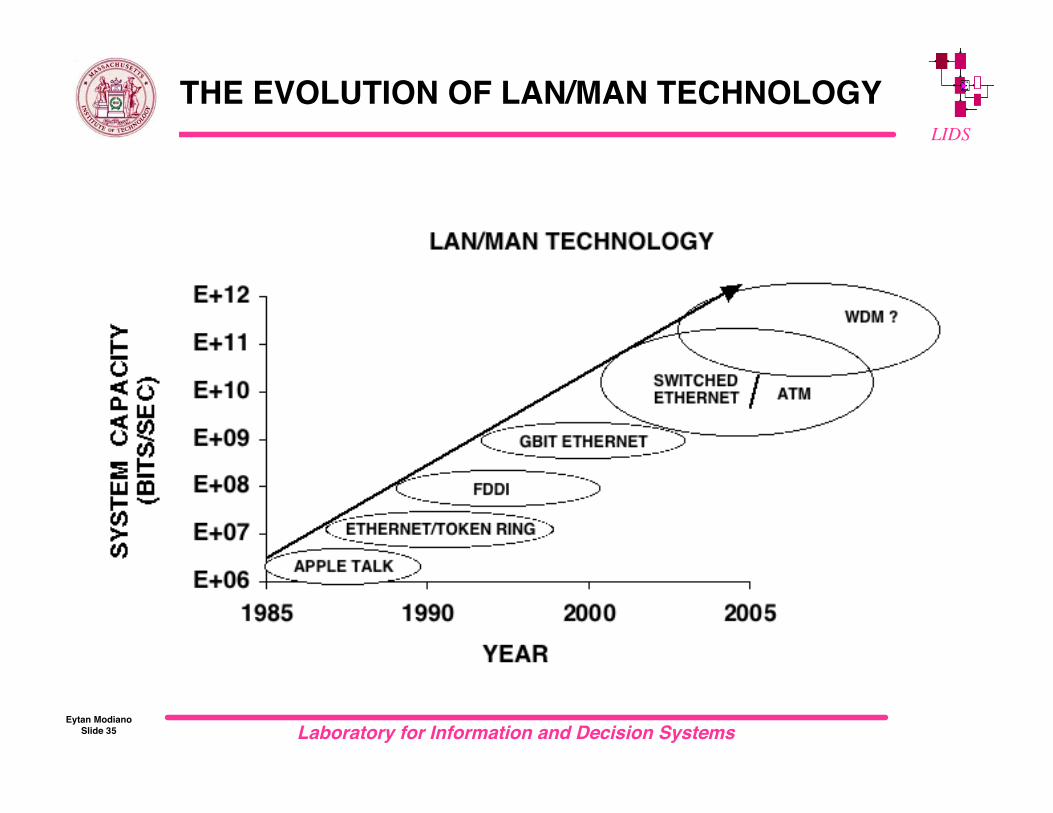
THE EVOLUTION OF LAN/MAN TECHNOLOGY
Laboratory for Information and Decision SystemsEytan Modiano
Slide 36
LIDS
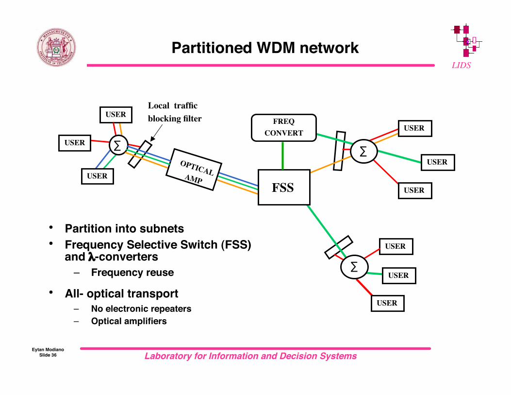
Partitioned WDM network
USER
USER
USER
USER
USER
USER
USER
USER
USER
FSS
OPTICALAMP
FREQCONVERT
Local trafficblocking filter
∑
∑
∑
• Partition into subnets• Frequency Selective Switch (FSS)
and λ-converters– Frequency reuse
• All- optical transport– No electronic repeaters– Optical amplifiers

Laboratory for Information and Decision SystemsEytan Modiano
Slide 37
LIDSHierarchical All-optical Network (AON)
LOCAL
FSS
FSS
LEVEL 2
OT OT OT OT OT OT OT OT
USER
OT
GLOBAL
METRO
Router
Star Star Star Star Star
Router Router
FSS
FSS
FSS
USERUSER USER
Laboratory for Information and Decision SystemsEytan Modiano
Slide 38
LIDS
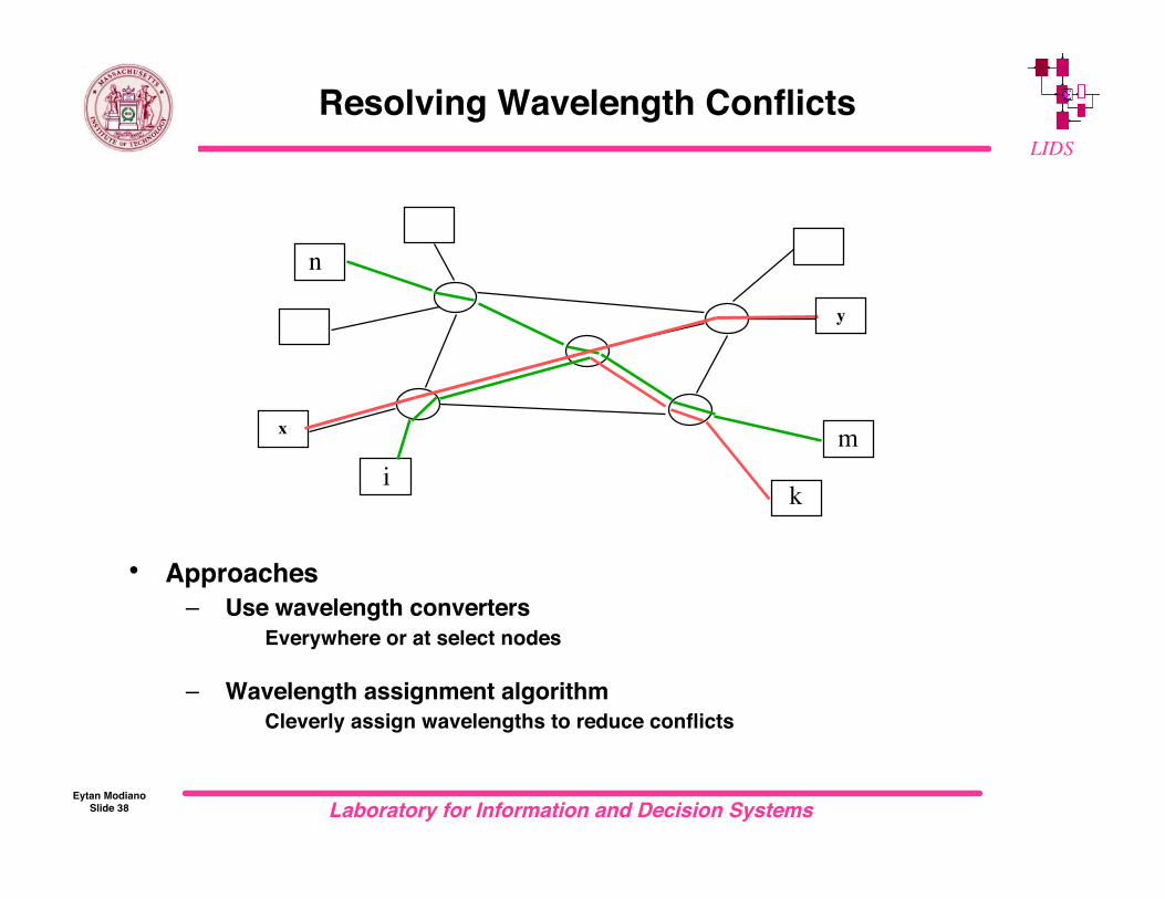
Resolving Wavelength Conflicts
• Approaches– Use wavelength converters
Everywhere or at select nodes
– Wavelength assignment algorithm Cleverly assign wavelengths to reduce conflicts
x
n
mi
k
y

Laboratory for Information and Decision SystemsEytan Modiano
Slide 39
LIDS
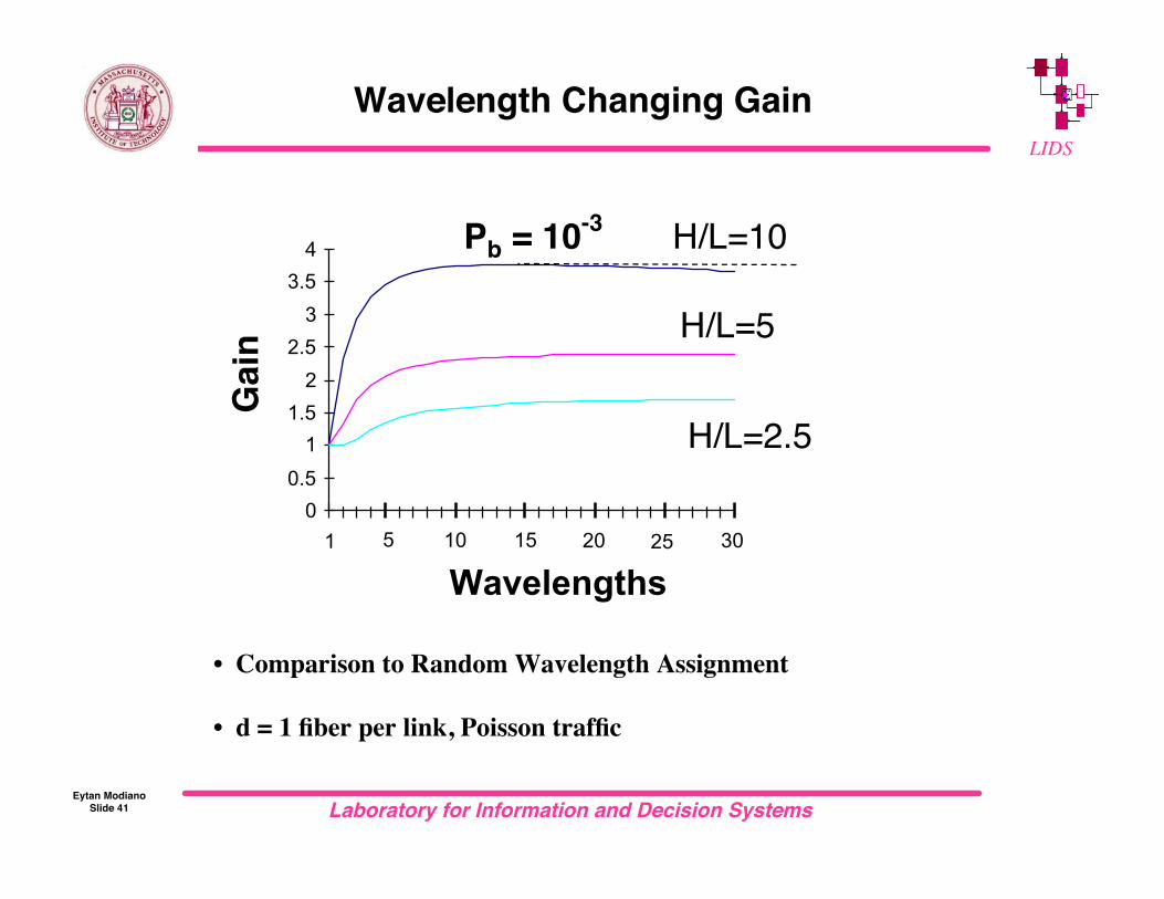
Wavelength Changing Gain
• Gain = Offered load (with λ−changers) Offered load (without λ−changers)
For same blocking probability pb = 0, 10-6..10-3
• Important factors
– H = Path length in hops Large H increases need for wavelength changers
– L = Interference length (average length of an interfering call) Large L reduces benefit of wavelength changers
– d = number of fibers per link Large d reduces benefit of wavelength changers

Laboratory for Information and Decision SystemsEytan Modiano
Slide 40
LIDS
Simple Analysis(Independence Approximation)
• Assume each wavelength is used on a link with probability p– Independent from link to link and wavelength to wavelength– approximation
• Consider a call of length H
• Without wavelength changers,– Pb = Pr(every wavelength is used on some link)
= [1 - P(wavelength is not used on any link)]W
= [1-(1-p)H]W
• With wavelength changers,– Pb = 1 - Pr(every link has at least one unused wavelength)
= 1 - (1-pW)H
• Analysis can be extended to include multiple fibers and accountfor interference length
Laboratory for Information and Decision SystemsEytan Modiano
Slide 41
LIDS
Wavelength Changing Gain
Wavelengths
Gai
nPb = 10-3 H/L=10
H/L=5
H/L=2.5
00.5
11.5
22.5
33.5
4
1 5 10 15 20 25 30
• Comparison to Random Wavelength Assignment
• d = 1 fiber per link, Poisson traffic

Laboratory for Information and Decision SystemsEytan Modiano
Slide 42
LIDS
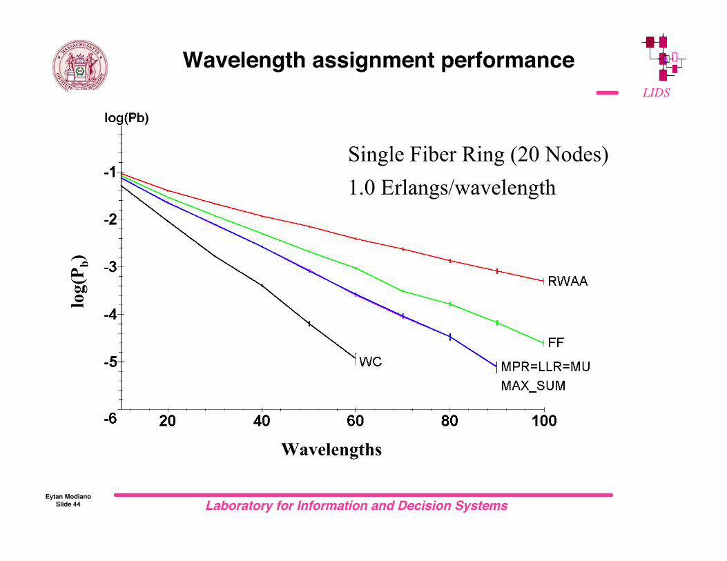
Wavelength Assignment Algorithms
Let Ω = candidate wavelengths
RANDOM: pick f ε Ω uniformly randomly
• FIRST FIT: pick lowest number f ε Ω
• MOST USED: pick f ε Ω used on the most links
• LEAST LOADED ROUTING: pick f ε Ω with least congested link along call path
• MAX_SUM (MΣ): pick f ε Ω which maximizes remaining excess capacity
3 wavelengths
bad assignment
!1
!3
!2
2 wavelengths
good assignment
!1
!2
!2

Laboratory for Information and Decision SystemsEytan Modiano
Slide 43
LIDS
Example
• New call between 4 and 5– All wavelengths are available– First Fit (FF) would select λ1 (red)– Most used would select λ2 (green)– Max sum would select λ4 (orange)
Disrupt the smallest number of potential future calls– Random may choose say blue…
1 2 3 4 5 6 7 8
λ1
λ4
Laboratory for Information and Decision SystemsEytan Modiano
Slide 44
LIDS
Wavelength assignment performance
Single Fiber Ring (20 Nodes)1.0 Erlangs/wavelength
Wavelengths
log(
P b)

Laboratory for Information and Decision SystemsEytan Modiano
Slide 45
LIDS
10-Fiber ring (20 nodes)1.6 Erlangs/wavelength
Wavelengths
log(
P b)
Wavelength assignment performance

Laboratory for Information and Decision SystemsEytan Modiano
Slide 46
LIDS
Status of Optical Networks
• All-optical networks are primarily in experimental test-beds
• WDM commercial marketplace is very active– Point to point WDM systems for backbone networks
Systems with up-to 80 wavelengths– WDM rings for access networks– WDM being used as a “physical” layer only
Network layer functions are done in electronic domain E.g., IP/SONET/WDM
• Hybrid electronic/optical networks appear to be the way to go– IP over WDM

Laboratory for Information and Decision SystemsEytan Modiano
Slide 47
LIDS
IP-over-WDM
• Networks use many layers– Inefficient, expensive
• Goal: reduced protocol stack– Eliminate electronic layers– Preserve functionality
• Joint design of electronic andoptical layers
– Virtual topology design– Traffic grooming– Optical layer protection
IP
ATM
SONET
WDM
Applications
TCP
WDM-awareIP
Applications
TCP
WDMIP router
WDM
Laboratory for Information and Decision SystemsEytan Modiano
Slide 48
LIDS
Optical layer protection
• Protection is needed to recover from fiber cuts, equipmentfailures, etc.
• Some protection is usually provided at higher layers– E.g., SONET loop-back
• So, why provide optical layer protection?– Sometimes higher layer protection is limited (e.g., IP)– Optical protection can be much faster– Optical layer protection can be more efficient
Restoring a single fiber cut is easier than 40 SONET rings Once restored optically, SONET can protect from more failures
– Also, SONET is mainly used for its protection capability so if we canprovide protection at the optical layer we can eliminate SONETequipment

Laboratory for Information and Decision SystemsEytan Modiano
Slide 49
LIDS
Optical protection mechanisms
• Path protection– Restore a lightpath using an alternative route from the source to the
destination Wavelength by wavelength
• Line protection– Restore all lightpaths on a failed link simultaneously by finding a
bypass for that link (loop-back)
• In rings techniques such as 1+1,1:1,1:n still apply
• In a mesh protection is more complicated– Path protection requires finding diverse routes– Line protection requires finding ring covers– Sharing protection resources
Establish backup paths in such a way that minimizes network resources
If two lightpaths share a common fiber they cannot share protectioncapacity

Laboratory for Information and Decision SystemsEytan Modiano
Slide 50
LIDS
Limitations of optical layer protection
• Cannot recover from electronic failures (e.g., line card)• Added overhead
– As much as 50% for 1:1 schemes– This overhead is on top of whatever overhead is used by the higher
layer For example, SONET uses an additional 50%
• Compatibility with higher layer protection mechanism
– SONET must recover from a fault in 60 ms– SONET starts to responds after 2.5 ms of disconnect
Can the optical layer recover before SONET detects a failure?
• Joint design of optical and electronic protection mechanisms
Laboratory for Information and Decision SystemsEytan Modiano
Slide 51
LIDS
Joint design of electronic and opticalprotection (example)
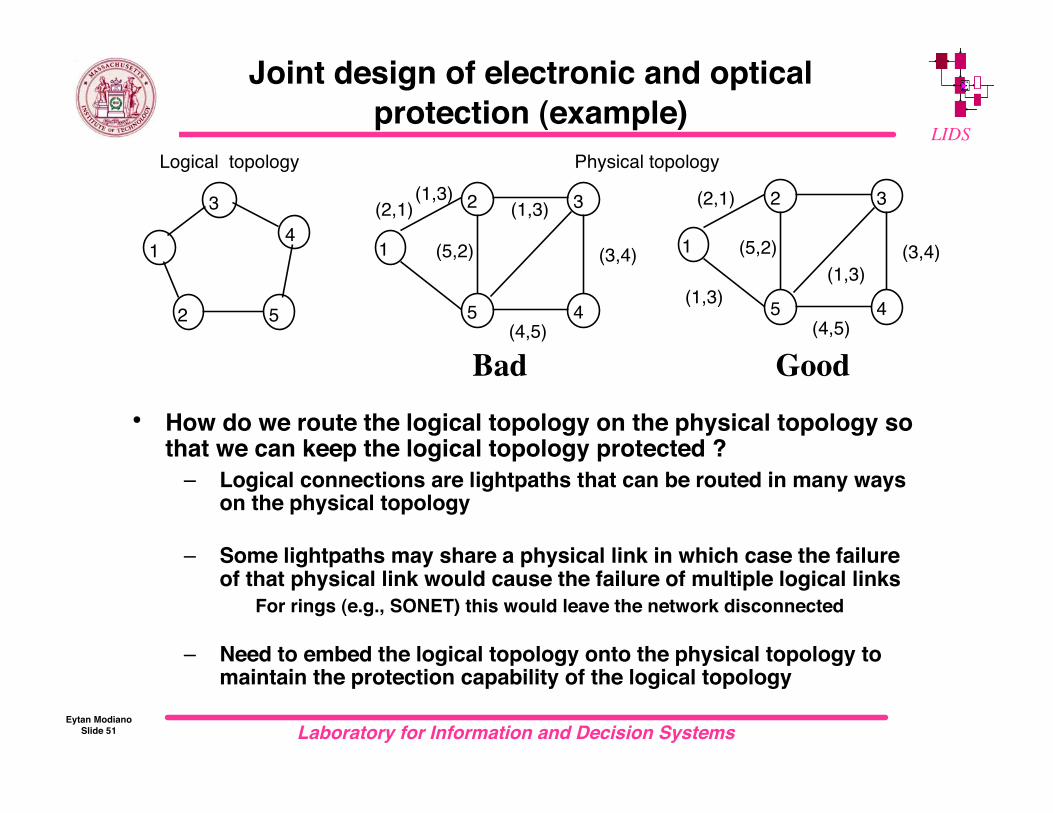
• How do we route the logical topology on the physical topology sothat we can keep the logical topology protected ?
– Logical connections are lightpaths that can be routed in many wayson the physical topology
– Some lightpaths may share a physical link in which case the failureof that physical link would cause the failure of multiple logical links
For rings (e.g., SONET) this would leave the network disconnected
– Need to embed the logical topology onto the physical topology tomaintain the protection capability of the logical topology
1
2 3
45
(1,3)(1,3)(2,1)
(3,4)
(4,5)
(5,2)
Physical topology
1
34
52
Logical topology
1
2 3
45(1,3)(1,3)
(2,1)
(3,4)
(4,5)
(5,2)
Bad Good
Laboratory for Information and Decision SystemsEytan Modiano
Slide 52
LIDS
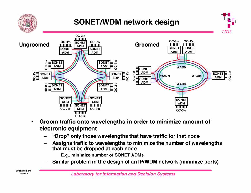
SONET/WDM network design
• Groom traffic onto wavelengths in order to minimize amount ofelectronic equipment
– “Drop” only those wavelengths that have traffic for that node– Assigns traffic to wavelengths to minimize the number of wavelengths
that must be dropped at each node E.g., minimize number of SONET ADMs
– Similar problem in the design of an IP/WDM network (minimize ports)
Ungroomed Groomed
Laboratory for Information and Decision SystemsEytan Modiano
Slide 53
LIDS
SONET Example
• Traffic grooming in a SONET ring network– Each wavelength can be used to support an OC-48 SONET ring– 16 OC-3 circuits on each OC-48 circuit– Each time a wavelength is dropped at a node a SONET ADM is needed– Assign OC-3 circuits onto OC-48 rings using the minimum number of ADMs
• Simple example:– Unidirectional ring with 4 nodes– 8 OC-3’s between each pair of nodes– traffic load:
6 node pairs 8 OC-3’s between each pair Total load = 48 OC-3’s 3 full OC-48 rings
– Each ring can support traffic between two node pairs
Laboratory for Information and Decision SystemsEytan Modiano
Slide 54
LIDS
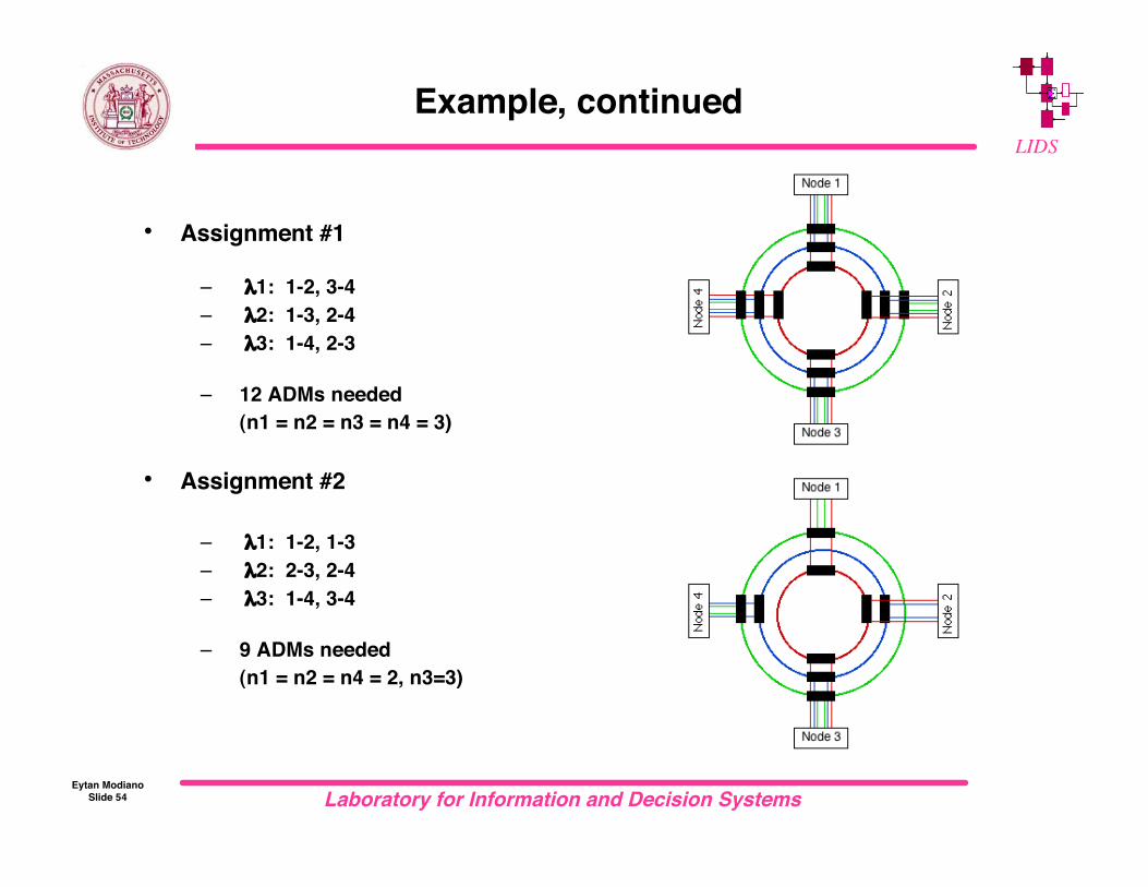
Example, continued
• Assignment #1
– λ1: 1-2, 3-4– λ2: 1-3, 2-4– λ3: 1-4, 2-3
– 12 ADMs needed(n1 = n2 = n3 = n4 = 3)
• Assignment #2
– λ1: 1-2, 1-3– λ2: 2-3, 2-4– λ3: 1-4, 3-4
– 9 ADMs needed(n1 = n2 = n4 = 2, n3=3)
Laboratory for Information and Decision SystemsEytan Modiano
Slide 55
LIDS
Future Trends
• Optical access
• Optical flow switching
• Logical topology (IP) reconfiguration
• All-optical packet switching

Laboratory for Information and Decision SystemsEytan Modiano
Slide 56
LIDS
COLLECTION & DISTRIBUTION
NETWORK (Passive Optics)
AN
FEEDERNETWORK
(configurable opticsand electronics)
Access Node Optical Switching Electrical Switching
ACCESS
TRANSPORT
SatelliteStation
Campus Network
Access Network Architecture
OpticalLAN
OpticalLAN
AN
CO
BACKBONENETWORK
AN
ANCO

Laboratory for Information and Decision SystemsEytan Modiano
Slide 57
LIDS
Optical flow switching
• Optical flow switching reduces the amount of electronicprocessing by switching long sessions at the WDM layer
– Lower costs, reduced delays, increased switch capacity– Today: IP over ATM (e.g., IP switching, tag switching, MPLS)
dynamically set-up new ATM VC’s to switch a long IP session Future: IP directly over WDM dynamically configure new lightpaths to optically switch a long session

Laboratory for Information and Decision SystemsEytan Modiano
Slide 58
LIDS
Topology Reconfiguration
• Reconfigure the electronic topology in response to changes intraffic conditions
– Electronic switches are connected using lightpaths– Lightpaths can be dynamically rearranged using WADMs
Reconfigure
Call Blocked Call Admitted

Laboratory for Information and Decision SystemsEytan Modiano
Slide 59
LIDS
Optical packet switched networks
• Wide area WDM networks are circuit (wavelength) switched– Limits scalability
• Packet switching is needed for scalable optical networks• In the LAN we saw that packet switching can be accomplished
using a MAC protocol– Requires fast tunable transceivers– This approach does not easily scale to wide areas
High latency Broadcast
• Optical packet switching isneeded for all-optical WANs
– Header processing– Packet routing– Optical buffers
• Do we really need all optical??
All-OpticalProcessing
Laboratory for Information and Decision SystemsEytan Modiano
Slide 60
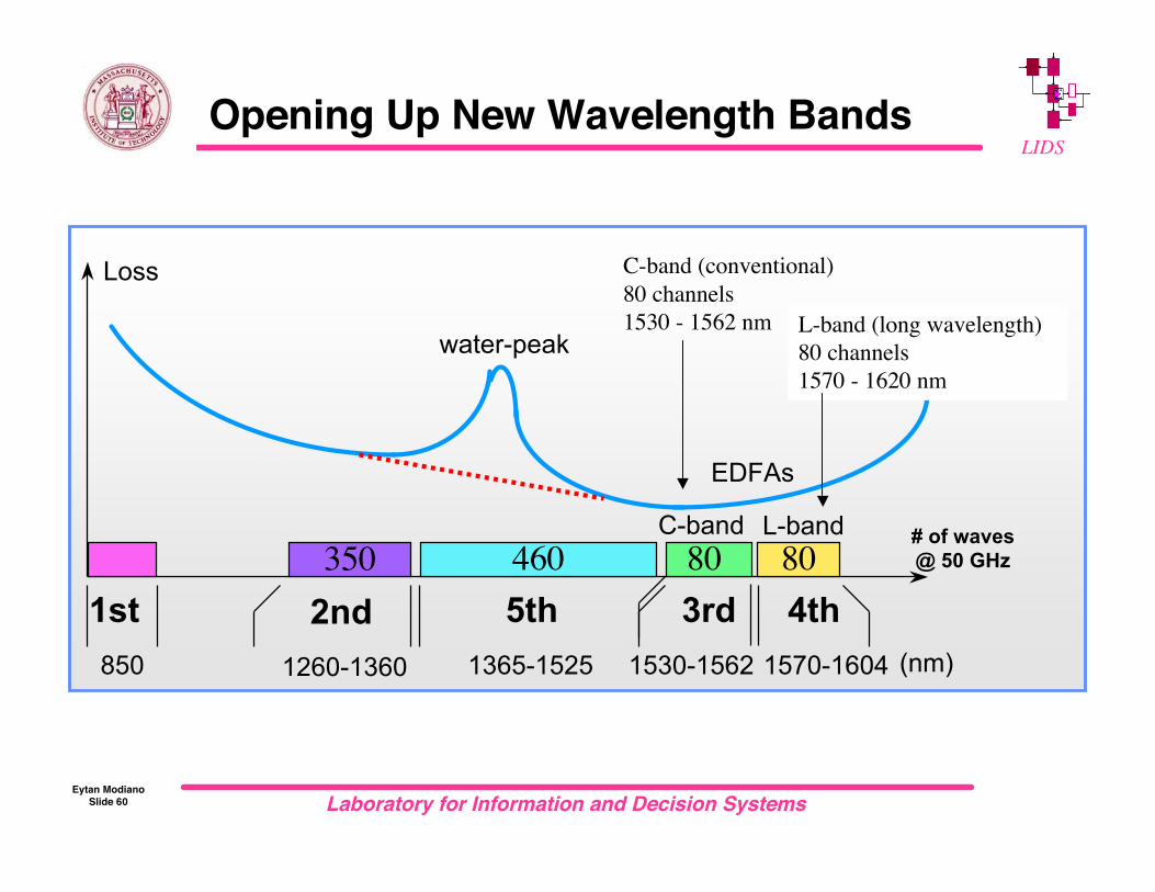
LIDSOpening Up New Wavelength Bands
350 80 460 80
water-peak
1260-1360 850 1530-1562
Loss
(nm)1365-1525 1570-1604
1st 2nd 3rd 4th5th
C-band L-band
EDFAs
# of waves@ 50 GHz
C-band (conventional)80 channels1530 - 1562 nm L-band (long wavelength)
80 channels1570 - 1620 nm

Laboratory for Information and Decision SystemsEytan Modiano
Slide 61
LIDSWDM Network Evolution
LINEAR RINGS MESHES
400 GHz
200 GHz100 GHz
50 GHz
Fixed add/drops
Configurable add/drops
Configurable switchesWavelength changers
Early-Mid ‘90s Late ‘90s - Early ‘00s Early ‘00s
Early ‘90s
Mid ‘90s
Late ‘90s
Late ‘90s
Late ‘90s
Early ‘00s
Early ‘00s
?

Laboratory for Information and Decision SystemsEytan Modiano
Slide 62
LIDS
Select References
• R. Ramaswami and K. N. Sivarajan, Optical Networks, MorganKaufmann, 1998
• B. Mukherjee, Optical Communication Networks, McGraw-Hill, 1997
• B. Mukherjee, WDM based Local Lightwave Networks, IEEE Network,May, 1992
• E. Modiano, WDM based Packet Networks, IEEE CommunicationsMagazine, March, 1999
• V.W.S. Chan, et. al. "Architectures and Technologies for High-SpeedOptical Data Networks," IEEE Journal of Lightwave Technology,December 1998.