Wireless Communication: Concepts, Techniques, and Models
37
Wireless Communication: Concepts, Techniques, and Models Hongwei Zhang http://www.cs.wayne.edu/~hzhang
Transcript of Wireless Communication: Concepts, Techniques, and Models

Wireless Communication: Concepts, Techniques, and Models
Hongwei Zhang
http://www.cs.wayne.edu/~hzhang

Outline
Digital communication over radio channels
Channel capacity
MIMO: diversity and parallel channels
Wideband systems: CDMA, OFDMA

Outline
Digital communication over radio channels
Channel capacity
MIMO: diversity and parallel channels
Wideband systems: CDMA, OFDMA

Digital communication over radio channels
Modulation and detection
Channel coding
Delay, path loss, shadowing, and fading

Digital communication over radio channels
Modulation and detection
Channel coding
Delay; path loss, shadowing, and fading

Modulation and detection
Modulation
modulating a sequence of pulses by the given bit stream
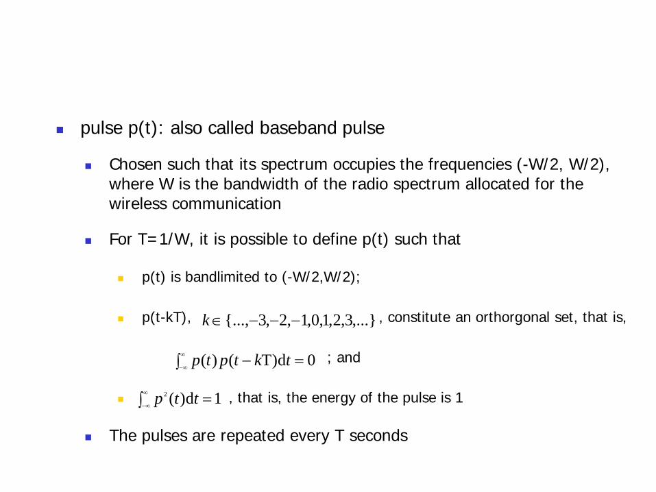
pulse p(t): also called baseband pulse
Chosen such that its spectrum occupies the frequencies (-W/2, W/2), where W is the bandwidth of the radio spectrum allocated for the wireless communication
For T=1/W, it is possible to define p(t) such that
p(t) is bandlimited to (-W/2,W/2);
p(t-kT), , constitute an orthorgonal set, that is,
; and
, that is, the energy of the pulse is 1
The pulses are repeated every T seconds
,...}3,2,1,0,1,2,3{..., −−−∈k
0d)T()( =∫ −∞
∞−tktptp
1d)(2 =∫∞
∞−ttp

Binary modulation and detection
Each pulse in the pulse train is multiplied by a symbol
from the symbol set
Bit 1: use symbol
Bit 0: use symbol
Let Ck be the symbol into which the k-th bit is mapped.
When the pulses are repeated every T seconds, the
modulated pulse stream can be written as
{ }ss EE ,−
sE
sE−
∑ −=∞
−∞=kk kTtpCtX )()(

The following operation will recover Ck
Before transmission, the baseband signal X(t) is translated
to the allocated radio spectrum with central frequency fc
by multiplying it with a sinusoid
s.t. the energy in the modulated symbols is Es
∫ −= ∞
∞- d)()( tkTtptXCk
∑ −=∞
−∞=kck tfkTtpCtS )2cos()(2)( π

Symbol-by-symbol channel model
Relates the source symbol sequence Ck and the predetection
statistic Yk, from which the source symbol has to be inferred
where Zk is a sequence of i.i.d. zero mean Gaussian random
variables with variance N0/2 (i.e., additive white Gaussian noise
AGWN)
kkk ZCY +=

)2(0N
EQP sAWGNerrorbit =
−−

In general, given a modulation scheme
where SNR is the signal power to noise power ratio
When considering interference
where SINR is the signal power to interference-plus-noise power ratio
)(SNRfP errorbit =−
)(SINRfP errorbit =−

Digital communication over radio channels
Modulation and detection
Channel coding
Delay; path loss, shadowing, and fading

Channel coding
To reduce bit-error-rate (BER)
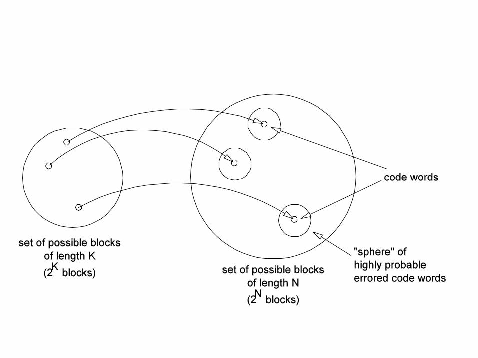

Shannon’s noisy channel coding theorem
There is a number C, called channel capacity, such that if the
information rate R<C, then, as the block length increases, an
arbitrary small BER can be achieved (of course, at the cost of a
large block coding delay);
If we attempt to use R>C, then BER cannot be reduced to 0.

Digital communication over radio channels
Modulation and detection
Channel coding
Delay; path loss, shadowing, and fading

Delay spread and inter-symbol interference (ISI) Delay spread Td
For a transmitter receiver pair, the difference between the smallest signal
delay and the largest signal delay
If delay spread is not very small compared to symbol time, then the
superposition of the signals received over the variously delayed paths
at the receiver leads to ISI; thus
where Jd denotes the length of channel memory (in # of symbols),
Gk(j) models the (attenuation) influence that the j-th past symbol has
on channel output at k, Ik models the interference, and Zk models
random background noise
∑ ++=−
=−
1
0)(
dJ
jkkjkkk ZIXjGY

Interpretation in frequency domain
Coherence bandwidth Wc: Wc = 1/Td
If Wc is small compared to W, superposition of variously delayed
versions of some frequency components in the baseband pulse
can cancel out;
In this case, some of the frequency components in the pulse get
selectively attenuated, leading to symbol corruption;
This is called frequency selective fading.
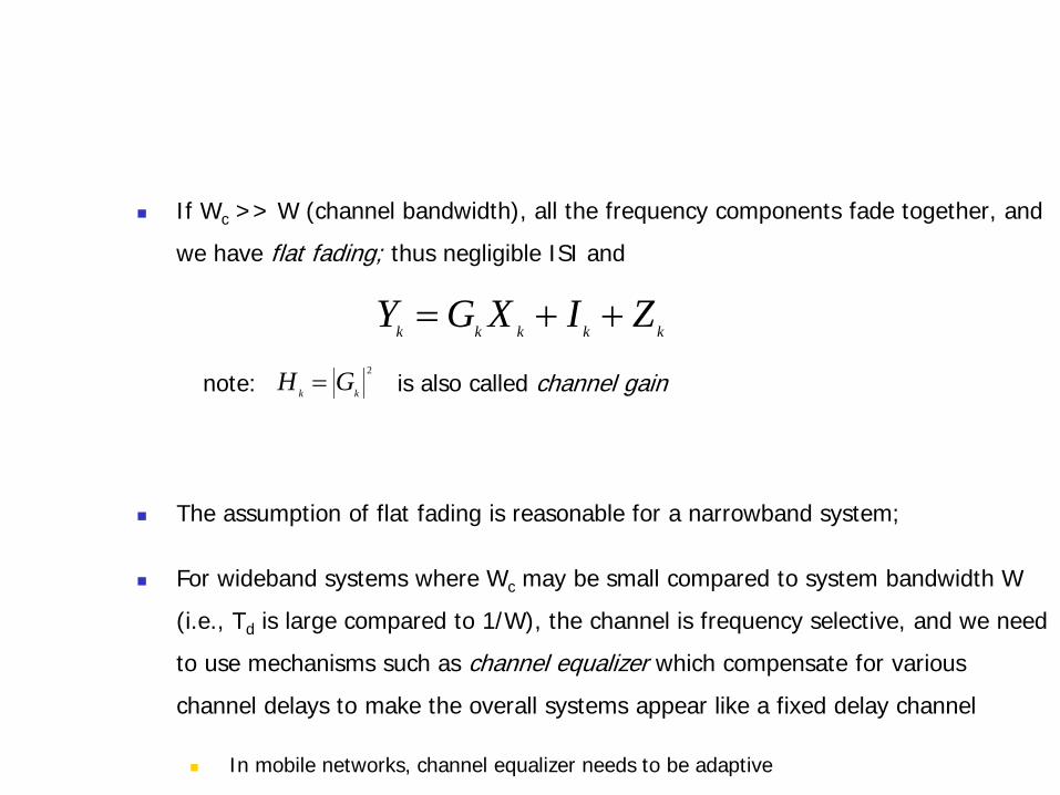
If Wc >> W (channel bandwidth), all the frequency components fade together, and
we have flat fading; thus negligible ISI and
note: is also called channel gain
The assumption of flat fading is reasonable for a narrowband system;
For wideband systems where Wc may be small compared to system bandwidth W
(i.e., Td is large compared to 1/W), the channel is frequency selective, and we need
to use mechanisms such as channel equalizer which compensate for various
channel delays to make the overall systems appear like a fixed delay channel
In mobile networks, channel equalizer needs to be adaptive
kkkkk ZIXGY ++=2
kk GH =

Power attenuation process: path loss, shadowing, fading
Channel power attenuation process Hk
Path loss factor:
d0: (far field) reference distance
η: path loss exponent; usually between 2 and 5
2
0
kkk
k RSddH
η−
=
η−
0ddk

Shadowing: Sk
Characterize the spatial variation in signal attenuation for the
same distance from transmitter
Usually follows a log-normal distribution, such that
dB. 8 is of valueA typical . varianceith Gaussian wmean zero a is dB log10
2
10
σσξ−=S

Multipath fading: Rk2
the superposition of delayed carriers results in constructive and
destructive carrier interference, leading to variations in signal
strength
Exists even if multipath time delays do not lead to ISI
it has strong autocorrelation over a duration of coherence time
Tc
Tc is approximately the inverse of the Doppler frequency
In indoor office or home environment, the Doppler frequency could
be just a few Hz (e.g., 3Hz), leading to coherence time of 100s of
milliseconds
cvff cd =

When all the signals arriving at the receiver are scattered
signals, R2 follow a Rayleigh distribution
When a fraction K/(K+1) of the signal arrives directly (i.e., line
of sight) and the remaining arrives uniformly over all directions,
R2 follows a Ricean distribution
( ))(/
2
2
2 )(1)( REx
Re
RExf −=
θπ
π θ d21)(
where)()1(2
)(1)(
2
0
)cos(
0
20
)()1(
2
2
2
∫=
++=
−
+−
x
RExKK
R
exI
RExKKIe
REKxf
Outline
Digital communication over radio channels
Channel capacity
MIMO: diversity and parallel channels
Wideband systems: CDMA, OFDMA

Channel capacity
Shannon’s Noisy Channel Capacity Theorem (without fading)
With fading: assuming the receiver can precisely track fading,
note:
density spectralpower noise theis where,1log 0
0
2 NWN
PWC rcv
+=
receiverat n informatio side)(or state channel :
d)(1log0
2
CSIR
hhgWN
hPWC Hxmt
CSIRfading ∫
+=
−
+≤
− WNPHEWC xmt
CSIRfading
0
2
)(1log

Outline
Digital communication over radio channels
Channel capacity
MIMO: diversity and parallel channels
Wideband systems: CDMA, OFDMA

SIMO
Exploiting the K (independently received)
signals at receiver can significantly reduce BER
Diversity gain: K
BER is proportional to ψ-K, where ψ is the receiver SNR
In contrast, in SISO with Rayleigh fading, BER
approximately decreases as the reciprocal of ψ (note:
approximate the Q(.) function)
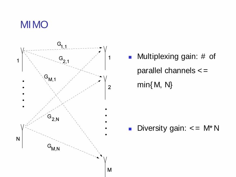
MIMO
Multiplexing gain: # of
parallel channels <=
min{M, N}
Diversity gain: <= M*N

Outline
Digital communication over radio channels
Channel capacity
MIMO: diversity and parallel channels
Wideband systems: CDMA, OFDMA

CDMA
Direct sequence spread spectrum (DSSS)
Each user symbol is multiplied by a spreading code of length L
chips
L is called the spreading factor
Spreading code
Take values in the set {-1, +1}L
Each code is approximately orthogonal to all the time shifts of
the other codes, and to its own time shifts

Effective pre-detection SINR
Scheduling in CDMA systems includes
allocating spread code and transmission power for each user
) (i.e., SINR received the times is which ,sinterferer 0,sinterferer 0, ∑ +∑ + ∈∈ j rcvj
rcv
j rcvj
rcv
WNPPL
WNPLP

OFDMA
Based on OFDM
statistically partitions the available spectrum into several
(e.g., 128 or 512) subchannels
Each subchannel has bandwidth B s.t. B << 1/Td, enabling
flat fading
If there are n subchannels, the OFDM block length is n
In the basic scheme, user bit stream is mapped into successive
blocks of n channel symbols that are then transmitted in
parallel
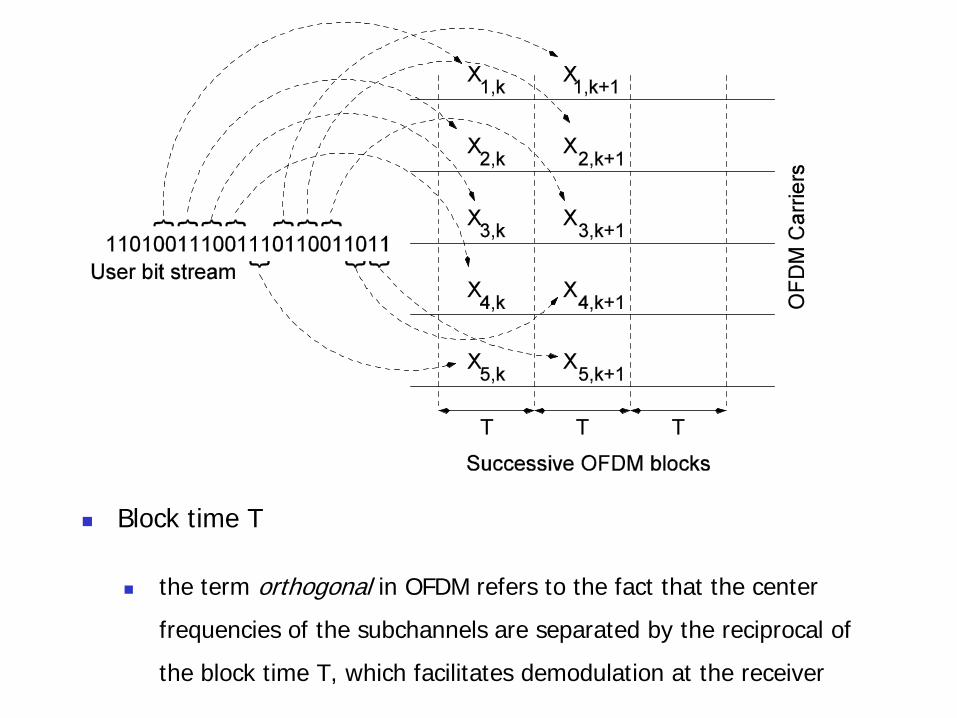
Block time T
the term orthogonal in OFDM refers to the fact that the center
frequencies of the subchannels are separated by the reciprocal of
the block time T, which facilitates demodulation at the receiver

It can be shown that fading is uncorrelated between
subcarriers that are spaced by more than the coherence
bandwidth, Wc Hz (= 1/Td)
Similar to how TDM exploits time diversity, OFDM exploits
frequency diversity: successive symbols of a user’s codeword
can occupy independently fading subcarriers.

Scheduling in OFDMA includes, depending on channel
conditions and user rate requirement,
Allocating a certain number of subcarriers to each user, and
Choosing the modulation schemes, channel coding scheme, and
transmission power from time to time
Resource allocation decisions in OFDMA can vary from
frame to frame, depending on channel conditions and
traffic demands
Summary
Digital communication over radio channels
Channel capacity
MIMO: diversity and parallel channels
Wideband systems: CDMA, OFDMA