Wireless Security David Wagner University of California, Berkeley.

Wireless Channels
Ada Poon, Bob Brodersen
Berkeley Wireless Research Center
University of California, Berkeley

Earth-Ionospheric Waveguide
3 – 30 kHz,very low frequency (VLF)
Large wavelength (>10 km)
Wave can’t penetrate to the lowest layer of ionosphere.
Long distance telegraphy broadcasting
Navigation systems
Submarine communications
Ionosphere
Earth

Surface Wave Diffraction
30 – 300 kHz,low frequency (LF)
Wave follows the curvature of earth.
Long distance communications
Navigation systems Earth
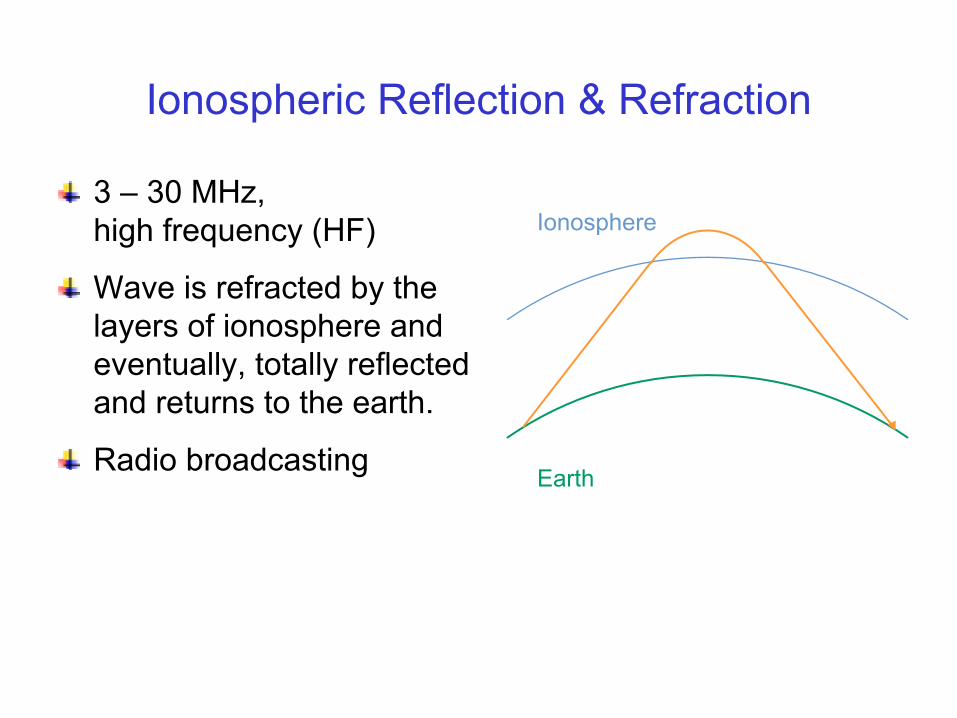
Ionospheric Reflection & Refraction
3 – 30 MHz,high frequency (HF)
Wave is refracted by the layers of ionosphere and eventually, totally reflected and returns to the earth.
Radio broadcasting
Ionosphere
Earth
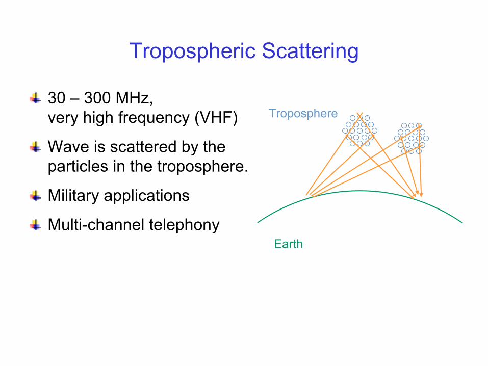
Tropospheric Scattering
30 – 300 MHz,very high frequency (VHF)
Wave is scattered by the particles in the troposphere.
Military applications
Multi-channel telephony
Troposphere
Earth

Four Basic Propagation Mechanisms
Waveguide
Diffraction
Reflection & Refraction
Scattering

Cellular Systems
Outdoor environment
0.3 – 3 GHz, ultra high frequency (UHF)
Propagation mechanisms:» Waveguiding along streets» Diffraction around hills» Reflection from buildings» Scattering by plants
Wireless LAN
Indoor environment
3 – 30 GHz, super high frequency (SHF)
Propagation mechanisms:» Waveguiding along corridors» Diffraction around door openings» Reflection from walls» Scattering by furniture

We are studying electrical engineering, but most of us don’t like to get too involved into classic electrodynamics.
Characterization Parameters
Path loss
Delay spread
Doppler shift
Angular spread
Coherence time
Coherence bandwidth

Friis Transmission Formula
PR = PT · ?
In free space, path loss is
d transmitter-receiver separationGR receiver antenna gainGT transmitter antenna gainλ wavelength
How about in a scattering environment?
( )2
2
2
2 41 −∝⋅= dGG
dPP TR
T
R
πλ

Path Loss Exponent, n
In a scattering environment, the path loss is
Typical values inUrban 2.7 – 3.5Sub-urban 3 – 5Indoor LOS 1.6 – 1.8 (< 2, why?)Indoor NLOS 2 – 6
n
T
R dPP −∝

UWB, LOS

802.11a, LOS
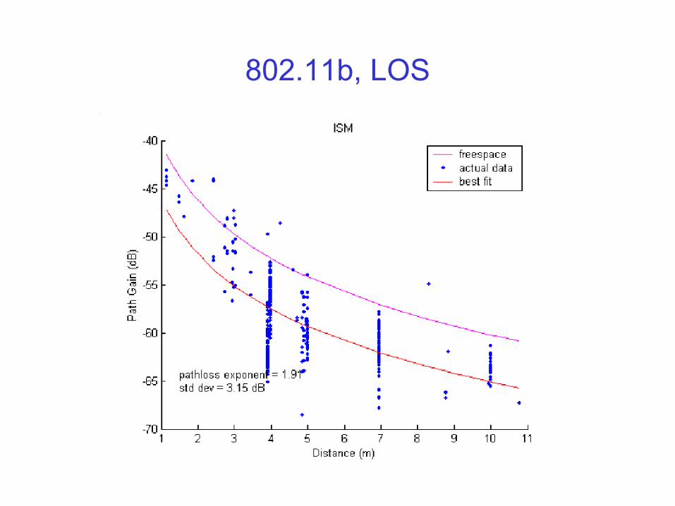
802.11b, LOS

UWB, NLOS

802.11a, NLOS
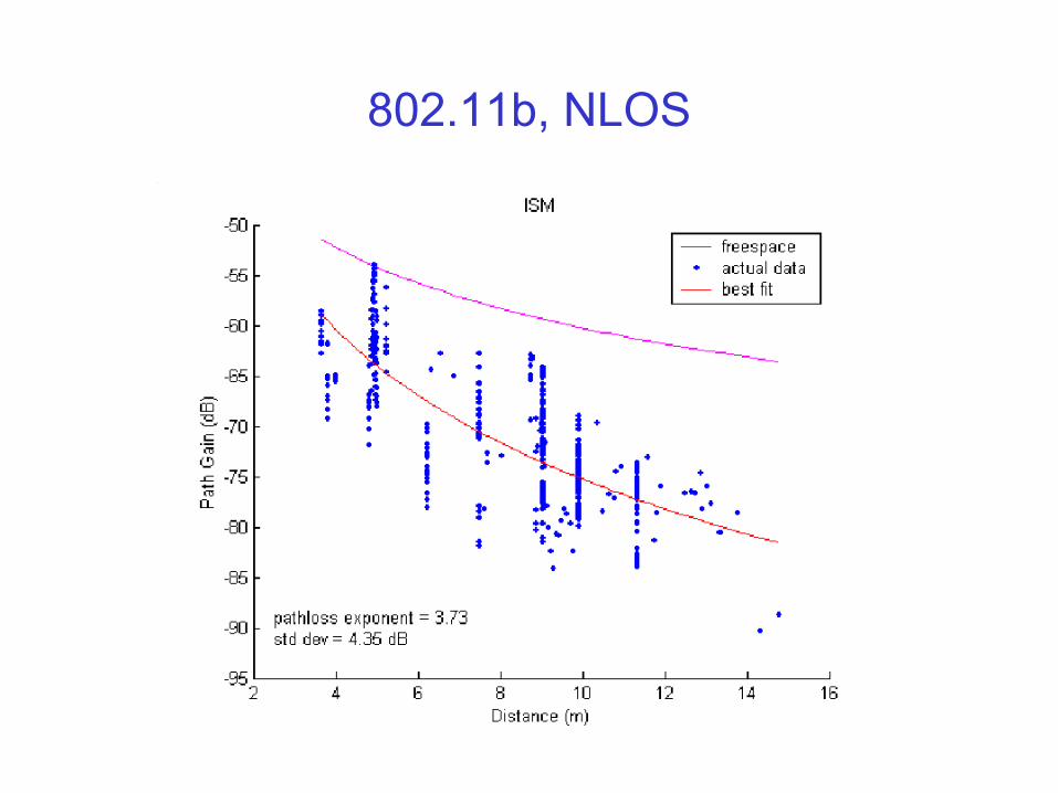
802.11b, NLOS
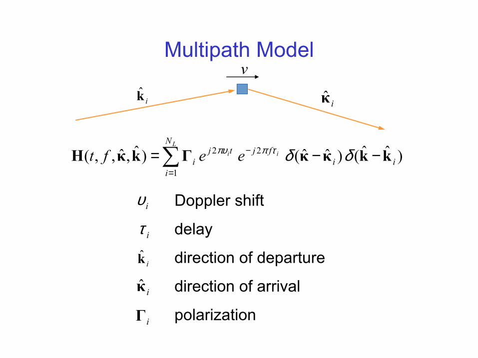
Multipath Model
iυ
iτ
iκ̂
∑=
− −−=L
ii
N
iii
fjtji eeft
1
22 )ˆˆ()ˆˆ()ˆ,ˆ,,( kkκκΓkκH δδτππυ
ik̂
iΓ
Doppler shift
delay
direction of departure
direction of arrival
polarization
ik̂ iκ̂
v

Maximum Doppler Shift
λυ vf im == max
Frequency spread, fm
For example, if a cell phone is moving at 60 km/hr using a 900 MHz carrier, the maximum Doppler shift is 50 Hz.
v

Delay Spread
Delay spread
1τ 2τ 3τ 4τt
iiiidT ττ minmax −=

Sample Measurements
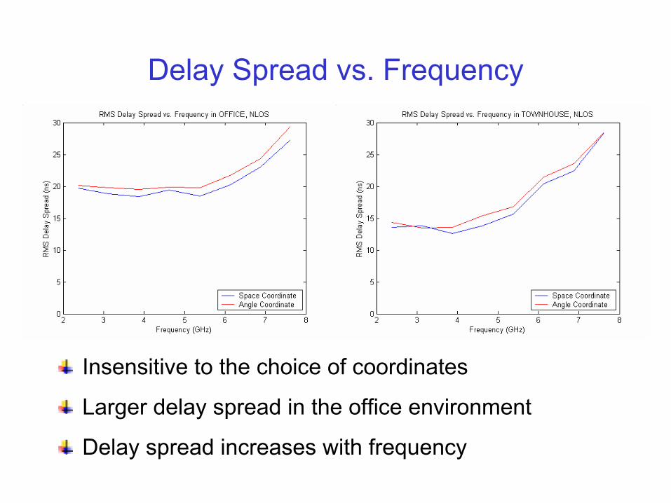
Delay Spread vs. Frequency
Insensitive to the choice of coordinates
Larger delay spread in the office environment
Delay spread increases with frequency
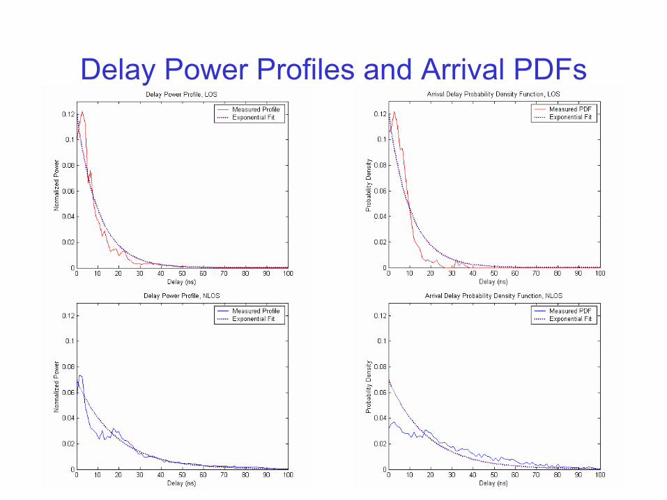
Delay Power Profiles and Arrival PDFs
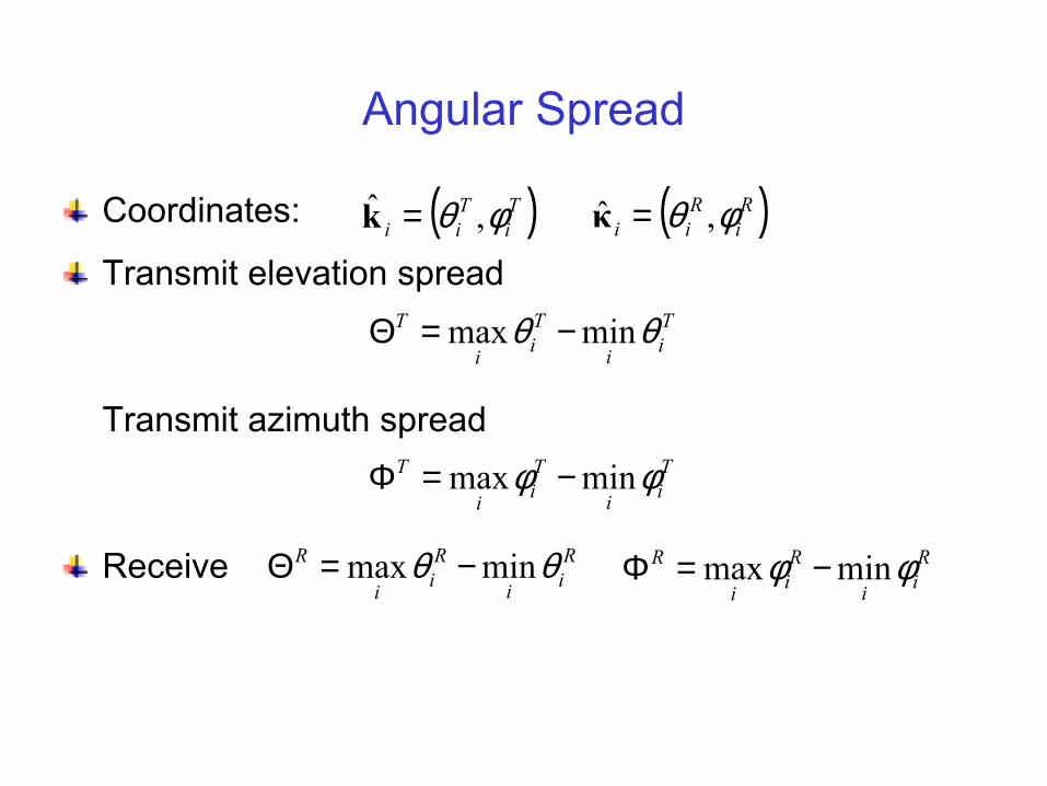
Angular Spread
Coordinates:
Transmit elevation spread
Transmit azimuth spread
Receive
Tii
Tii
T θθ minmax −=Θ
( )Ti
Tii φθ ,ˆ =k ( )R
iR
ii φθ ,ˆ =κ
Tii
Tii
T φφ minmax −=Φ
Rii
Rii
R θθ minmax −=Θ Rii
Rii
R φφ minmax −=Φ

Sample Measurements

Angle Power Profiles and Arrival PDFs

∑=
− −−=L
ii
N
iii
fjtji eeft
1
22 )ˆˆ()ˆˆ()ˆ,ˆ,,( kkκκΓkκH δδτππυ
Coherence Bandwidth, Coherence Time
[ ] 0~)ˆ,ˆ,,()ˆ,ˆ,,( * kκHkκH ftfTt c+Ε
Coherence time, Tc
Coherence bandwidth, Wc
ik̂ iκ̂
v
[ ] 0~)ˆ,ˆ,,()ˆ,ˆ,,( * kκHkκH ftWft c+Ε
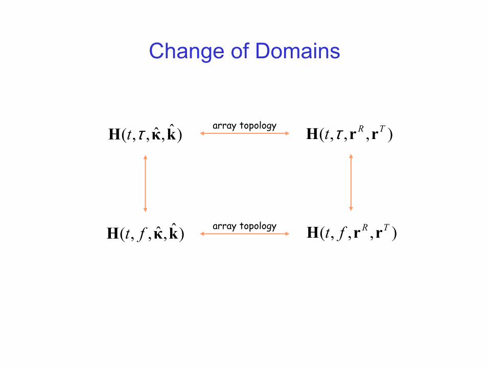
Change of Domains
)ˆ,ˆ,,( kκH ft
)ˆ,ˆ,,( kκH τt
),,,( TRft rrH
array topology
array topology
),,,( TRt rrH τ

Channel Characterization
(υi, τi, θi)’sextraction
geometry & dielectric
properties of environment
effective scatterer
distribution
distribution
(t, f, rR, rT) correlation
Measurement Ray tracing Abstract modeling
array topology
frequency spreaddelay spread,angular spread
coherence timecoherence bandwidth
),,,( θ∆θτ∆τ
path loss