WIPP Strategic Plan Operations Through 2050 · The Strategic Plan communicates the emplacement...
46
OBSOLETE 15-GM.14, Rev. 0 1 | Page WIPP Strategic Plan Operations Through 2050 June 27, 2016
Transcript of WIPP Strategic Plan Operations Through 2050 · The Strategic Plan communicates the emplacement...

OBSOLETE 15-GM.14, Rev. 0
1 | P a g e
WIPP Strategic Plan
Operations Through 2050
June 27, 2016

OBSOLETE 15-GM.14, Rev. 0
2 | P a g e
Author:
Approved By:
Brian Stubbs
Tammy Reynolds
Approval on File
Approval on File

OBSOLETE 15-GM.14, Rev. 0
3 | P a g e
1. Introduction ......................................................................................................................................... 5
1.1. Mission ......................................................................................................................................... 5
1.2. Objective ...................................................................................................................................... 5
1.3. History .......................................................................................................................................... 5
2. WIPP System Description .............................................................................................................. 7
2.1. Surface Facilities: Contributions to Mission .............................................................................. 8
2.2. Shafts and Underground Facilities: Contributions to Mission ............................................... 10
2.3. Ventilation Systems: Contribution to Mission ........................................................................ 11
2.4. Fire Protection System: Contribution to Mission ................................................................... 12
2.5. Fire Water Supply and Distribution System: Contribution to Mission ................................. 12
2.6. Water Use: Contribution to Mission ........................................................................................ 13
2.7. Electrical System: Contribution to Mission ............................................................................. 13
2.8. Maintenance Program: Contribution to Mission .................................................................... 14
2.9. Current Operating Conditions .................................................................................................. 14
3. Approach ....................................................................................................................................... 15
4. Summary and Results .................................................................................................................. 16
4.1. Waste Emplacement Rate ......................................................................................................... 16
4.1.1. Contaminated Waste Emplacement Rate ............................................................................. 17
4.1.2. Non-Contaminated Waste Emplacement Rate ..................................................................... 18
4.2. Availability ................................................................................................................................. 19
4.3. WIPP Recommended Path Forward ........................................................................................ 21
4.3.1. Summary ................................................................................................................................. 21
4.3.2. Description of Assumptions and Bases ................................................................................ 22
4.3.3. 5 Year Funding Requirements ............................................................................................... 22
4.4. Alternative Analysis: No Emplacement in Panels 9 and 10 ................................................... 23
4.4.1. Summary ................................................................................................................................. 23
4.4.2. Funding: .................................................................................................................................. 24
4.5. Regulatory Drivers .................................................................................................................... 24
4.6 Strategic Alignment ........................................................................................................................... 25
4.6.1 National TRU Waste Management Plan ............................................................................... 26
4.6.2 WIPP FY2016 to FY2026 Ten-Year Site Plan .......................................................................... 26
4.6.3 FY2018 NWP Integrated Priority List .................................................................................... 26

OBSOLETE 15-GM.14, Rev. 0
4 | P a g e
4.6.4 CBFO Strategic Plan ............................................................................................................... 27
5 Quality Assurance and Risk Management .......................................................................................... 27
5.1 Quality Assurance……………………………………………………………………………………………………………….27
5.2 Risk Management .................................................................................................................... 27
6 Future Considerations ......................................................................................................................... 28
7 References .......................................................................................................................................... 28

OBSOLETE 15-GM.14, Rev. 0
5 | P a g e
Executive Summary Approximately 91,000 cubic meters of TRU waste has been emplaced in the underground repository since receipt and disposal operations began at the Waste Isolation Pilot Plant (WIPP) in March 1999. Waste emplacement operations were suspended in February 2014 following two separate underground events. The goal of this Strategic Plan is to provide an overarching strategy and plan for WIPP to achieve its operational lifetime through Fiscal Year (FY) 2050. WIPP’s mission objective will be met through a combination of: ensuring WIPP facility infrastructure supports long-term operations missions; optimizing operational practices; optimizing transportation and TRU waste system logistics; implementing facility upgrades that enhance waste receipt capacity and/or process efficiency and working with regulators to optimize the regulatory framework. This Strategic Plan will serve as input to and align with the National TRU Waste Management Plan, the WIPP Ten Year Site Plan, the Integrated Project List and the Carlsbad Field Office (CBFO) Strategic Plan as these documents mature. The Strategic Plan communicates the emplacement rates WIPP is projected to achieve during operations following restart, expected in late calendar year 2016. Following a period of deliberate operations upon restart, WIPP is predicted to average five shipments per week. Management estimates process improvement and efficiencies implemented over time will increase emplacement rates, and emplacement rates could increase should the radiological conditions improve. Planned projects, mining, outages, ventilation, permit actions, emplacement rates, and availability are laid out by fiscal year on the WIPP Strategic Plan Schedule (Attachment 1). This tool helps in understanding the complex relationship of these elements, and is used for long term planning, decision making, and determination of funding requirements. There are many interrelated factors and open decisions involved with the use of panels 9 and 10 for waste disposal, permanent panel closure of interim closed panels, and where to place mined salt. It is recommended that a stakeholder/decision maker workshop, working group, or integrated project team be chartered to work through the various options and document a decision for the best path forward. Also key to the conclusions of this strategic plan is timely execution of the permanent ventilation system (PVS) project. The plan assumes the PVS will be available to allow concurrent mining/waste emplacement and to eliminate filter change impacts to waste emplacement, which allows operational flexibility and significantly improves throughput. Another significant assumption of this plan is that in order for NWP to safely continue the mission of emplacing the nation’s TRU waste from restart of operations until mission

OBSOLETE 15-GM.14, Rev. 0
6 | P a g e
completion in 2050, substantial repairs or replacements of existing structures, facilities and properties are needed within the next five years. This Strategic Plan will be updated annually to align with the latest progress and future strategy. The target for the updates will be in the January to March timeframe to coincide with the Federal budget cycle. The model/simulation software will serve as an input to a WIPP Strategic Plan. The plan will continue to align with other strategic efforts and serve as a roadmap for WIPP’s lifecycle operations through 2050. 1. Introduction
1.1. Mission The Mission of the WIPP is to provide a safe and permanent disposal location for the nation’s defense-related TRU and TRU mixed radioactive wastes. The current WIPP mission includes the disposal of both Contact-Handled (CH) waste (i.e., waste with a radiation level of less than 200 millirem per hour at the surface of the waste container) and Remote-Handled (RH) waste (i.e., waste with a radiation level of equal to or greater than 200 millirem per hours, but less than 1,000 rem per hour) in its underground repository. Approximately 96 percent of the total volume of waste to be disposed at WIPP is CH TRU waste. The remaining four percent of the waste volume is RH TRU waste.
1.2. Objective The WIPP objective is to become the permanent disposal repository for the nation’s approximate 175,000 cubic meters of TRU and TRU mixed wastes.
1.3. History The U.S. Department of Energy’s (DOE) Waste Isolation Pilot Plant is the nation’s only repository for the permanent disposal of waste that is the byproduct of the nation’s nuclear defense program. The waste, known as transuranic, or TRU, consists of clothing, tools, rags, residues, debris, soil and other items contaminated with small amounts of plutonium and other man-made radioactive elements. Disposal of TRU and TRU mixed waste is critical to the cleanup of Cold War nuclear productions sites. TRU and TRU mixed waste from DOE sites around the country is sent to WIPP for permanent disposal. The WIPP site is located 26 miles southeast of Carlsbad, NM, in the Chihuahuan Desert, far from major population centers. Its disposal rooms are located nearly one half mile below the service (2,150 feet) in a deep geologic salt bed, which was formed 250 million years ago. Construction of the WIPP site started in the early 1980s after completion of a site selection study in which several locations in southeast New Mexico were evaluated. The present site was selected based on extensive geotechnical research supplemented by testing. In 1992, the WIPP facility property was transferred from the U.S. Department of the Interior to the

OBSOLETE 15-GM.14, Rev. 0
7 | P a g e
DOE. Consistent with the WIPP mission, land within and around the WIPP site boundary is administered according to a multiple land-use policy. During operations, the area within the WIPP site boundary will remain under federal control. After completion of facility construction, WIPP entered into its current life-cycle phase, which is disposal of TRU and TRU mixed wastes. WIPP began receipt and disposal of CH Waste in March 1999 and RH Waste in January 2007. The disposal phase is planned to last 35 years. Prime regulators at WIPP are the Environmental Protection Agency (EPA) and the New Mexico Environment Department (NMED). A number of other agencies, committees and panels, monitor WIPP’s progress and contribute to project success. The DOE Carlsbad Field Office (CBFO), which leads the nation’s TRU waste disposal effort, has coordinated TRU waste cleanup at a number of the generator sites around the country and will continue to do so until the WIPP mission is accomplished in 2050. On February 5, 2014, a fire occurred in the underground involving a Salt Haul Truck. This event was investigated by both DOE and NWP. The DOE Accident Investigation Report (U.S. Department of Energy Accident Investigation Report, Underground Salt Haul Truck Fire at the Waste Isolation Pilot Plant, February 5, 2014) was issued on March 13, 2015, with 22 Conclusions of Need and 35 Judgments of Need. On February 14, 2014, a radioactive release event occurred in the underground due to an exothermic reaction in a drum noncompliant with the WIPP waste acceptance criteria. This resulted in a small release of radioactive material into the environment. The Phase 1 DOE Accident Investigation Report was issued on April 22, 2014, with 31 Conclusions of Need and 47 Judgments of Need. The Phase 2 Accident Investigation Report was issued on April 16, 2015, with 24 Conclusions of Need and 40 Judgments of Need. The U.S. Department of Energy Accident Fire Forensic Analysis of the Radiological Release Event at the Waste Isolation Pilot Project on February 14, 2014 was issued by DOE on April 6, 2015. NWP immediately initiated a Recovery Plan that addressed the Accident Investigation Reports’ conclusions and judgements and have now entered into a re-start of operations phase, which will result in the commencement of waste emplacement this year (CY16). 2. WIPP System Description The land area within the WIPP Land Withdrawal Area, or the WIPP site boundary, is 16 square miles and contains 10,240 acres. The area containing the WIPP surface structures is surrounded with a chain link fence and covers about 35 acres. This fenced area is the WIPP Property Protection Area (PPA). Inside the PPA are 58 surface structures, support

OBSOLETE 15-GM.14, Rev. 0
8 | P a g e
facilities and essential properties for the WIPP mission. The square footage of these is 395,269 sq. ft. These structures, facilities and properties include:
• Waste Handling Building (WHB) • Four shafts to the underground
(UG) area • Support Building • Exhaust Filter Building • Water storage tanks and pump
house • Modular trailers • Two warehouses • Sewage stabilization ponds • Meteorological tower • Mined rock / salt piles • Evaporation ponds
The underground (UG) facility is located centrally within the WIPP site boundary and covers a footprint of 550 acres. The UG facility is 2,150 feet below the surface in bedded salt of the Permian Salado Formation and is connected to the surface by the four shafts: Air Intake Shaft, Salt Handling Shaft, Exhaust Shaft and the Waste Shaft. Access to the WIPP site is provided by two roads that connect with U.S. Highway 62/180, 13 miles to the north, and New Mexico Highway 128, four miles to the south. The north access road is used to transport TRU mixed waste from U.S. Highway 62/180 to the site. The north access road is used as the primary transportation route by personnel, agents and contractors of the DOE on official business related to the WIPP and by personnel, permittees, licensees or lessees of the Bureau of Land Management (BLM). The south access road is a multiple-use access. Both roads are maintained by DOE. The principal operations at WIPP involve the receipt and disposal of TRU waste. WIPP Contact-Handled (CH) and Remote-Handled (RH) waste operations include the following:
• Receipt, movement and emplacement of CH waste containers with battery-powered and diesel fueled forklifts, electric-powered Automated Guided Vehicles, cranes, the Waste Hoist, and UG transporter
• Receipt, movement and emplacement of RH Waste Containers with cranes, transfer cars, the Waste Hoist, UG 41-ton diesel-fueled forklift, and the Horizontal Emplacement and Retrieval Equipment (HERE) or Horizontal Emplacement Machine (HEM).
• Retrieval, movement and shipment of CH and RH Waste Containers, if required. • Maintenance and operation of surface and UG Waste Handling equipment and
engineered features. • Maintenance of surface buildings and outside areas. • Maintenance and preparation (i.e., mining) of the UG disposal facility.

OBSOLETE 15-GM.14, Rev. 0
9 | P a g e
In order to safely operate and dispose of the TRU waste until 2050, all surface and UG facilities, process systems and equipment must be maintained, upgraded or replaced. This section will focus on these facilities and systems by explaining each one’s contribution to the WIPP mission, the current condition they are in and recommendations for upgrades or replacements when needed. 2.1. Surface Facilities: Contributions to Mission Waste Handling Building (WHB) The WHB is a structure in which CH and RH wastes are handled, inspected, stored and moved prior to emplacement in the UG. CH and RH wastes enters the WHB in specially designed shipping packages and are unloaded. Once the waste is prepared for emplacement, it is transported to the Waste Shaft Access Area. The Waste Shaft Access Area provides access in separate locations for the CH and RH waste. The WHB structure protects various rooms, including the CH Bay, Room 108, RH Bay, cask loading room, transfer cell and waste hoist tower. Contiguous and/ or connected to the WHB are the TRUPACT maintenance facility, Support Building, Exhaust Filter Building and Main Access Corridor. Waste Hoist Support Structure The Waste Hoist is used to lower and raise waste packages to and from the UG and is located directly over the Waste Shaft. The hoist and its associated components are supported by a robust structure that consists of four steel I-beam columns that is mounted on a substantial concrete foundation, which supports four steel I-beam girders, bedplate, friction drum, drum shaft and six head ropes that fully support the waste conveyance. The Waste Hoist Support Structure is capable of supporting a conveyance of 33 tons, a counterweight of 52 tons and a design payload of 45 tons. Waste Hoist Tower The Waste Hoist Tower, located between the CH and RH portions of the WHB, is five floors high. The first floor is the Waste Shaft Collar Room. The Waste Hoist Master Control
The Waste Handling Building with the Support Building in the foreground.

OBSOLETE 15-GM.14, Rev. 0
10 | P a g e
Station is on the second floor. The Waste Hoist motor, brakes, maintenance cranes and associated hydraulic systems are located on the fifth floor. CH Bay The CH Bay is an area of the WHB used for removing CH waste assemblies from TRUPACT-IIs, TRUPACT-IIIs and Half PACTS and preparing the assemblies for disposal. The waste is removed from the containers at a TRUDOCK station and placed on a facility pallet. After a waste load is prepared on the pallet, the pallet is stored or removed to the Waste Shaft Access Area for downloading into the UG. Room 108 Room 108 is a room in the WHB used for removing Standard Large Box 2 (SLB2) from TRUPACT-IIs and placing the SLB2 on a facility pallet. After a SLB2 is placed on the pallet, the pallet is moved into the CH Bay for storage or moved to the Waste Shaft Access Area for downloading. RH Bay The RH Bay is an area inside the WHB used for removing RH-TRU 72-B road cask shipping containers from the transport trailer. The impact limiters and outer lid of the containers are removed and the cask is moved into the Hot Cell Complex for processing. Hot Cell Complex The Hot Cell Complex is a series of shielded rooms inside the WHB used for transferring the RH waste from the 72-B road cask to the facility cask. The RH 72-B road cask is moved from the cask unloading room, placed in the transfer cell and moved to a position under the facility cask loading room (FCLR). Waste Shaft Access Area The Waste Shaft Access Area is inside the WHB and includes the FCLR, conveyance loading room, Waste Shaft Collar Room and the Waste Hoist Tower. The FCLR is the room where the RH canister is loaded into the facility cask and prepared for transfer to the UG via the Waste Shaft Conveyance. The Conveyance Loading Room (CLR) is the room where a CH Waste loaded facility pallet is prepared for transfer to the UG via the Waste Shaft Conveyance. The Waste Shaft Collar Room is where the Waste Shaft Conveyance is positioned and waste is loaded onto the Waste Shaft Conveyance. The Waste Hoist Tower contains the Waste Hoist Master Control Station, the support frame and support components for the Waste Hoist.

OBSOLETE 15-GM.14, Rev. 0
11 | P a g e
Support Building The Support Building is located on the south side of the main east to west road, and north of the WHB. The Support Building provides housing for administrative activities, change rooms, laboratories, operational support activities, and the Central Monitoring Room (CMR). The CMR is located on the second floor and provides space for the Central Monitoring System (CMS). The CMS is a computerized system that monitors specific equipment functions and conditions of the UG, the WHB, and its support systems such as HVAC and fire alarms. Exhaust Filter Building The Exhaust Filter Building (EFB) contains the UG Ventilation Exhaust HEPA filtration equipment and is located north of the Exhaust Shaft. The EFB provides for walk-in HEPA filter change-out. During normal operations, air is pulled into the UG from the Air Intake Shaft, Salt Handling Shaft, and Waste Shaft. Air is drawn up the Exhaust Shaft and then filtered before discharging to the atmosphere. Approximately 60,000 actual cubic feet per minute (acfm) is pulled through the EFB HEPA filtration equipment by one of three 860 fans. Two interim skid-mounted HEPA filter and fan units (the Interim Ventilation System [IVS]) can be used to add approximately 54,000 acfm filtered airflow from the UG. 2.2. Shafts and Underground Facilities: Contributions to Mission There are four WIPP shafts: Air Intake, Salt Handling, Waste and Exhaust. The Salt Handling Shaft extends about 110 feet below the disposal level to provide a salt loading pocket and a sump. The Waste Shaft extends about 118 feet below the disposal level to accommodate tail rope dividers, guide rope weights, and a sump. The Salt Handling Shaft is the only means of hoisting mined salt. It is a secondary source of intake air, exhausts air for Supplemental Ventilation System (SVS) operation, and is a route for power, control, and communications cables from the surface to the UG. The Air Intake Shaft is the primary source of intake for UG ventilation. The Waste Shaft provides the only means of lowering TRU Waste for disposal. It is the source of air for ventilating the Waste Shaft Station and is a route for power, control, and communications cables from the surface to the UG. The Waste Shaft has an Auxiliary Air Intake Tunnel to provide additional airflow to the Waste Shaft Station by adjusting dampers and balancing pressure in the Waste Hoist Tower.
OBSOLETE 15-GM.14, Rev. 0
12 | P a g e
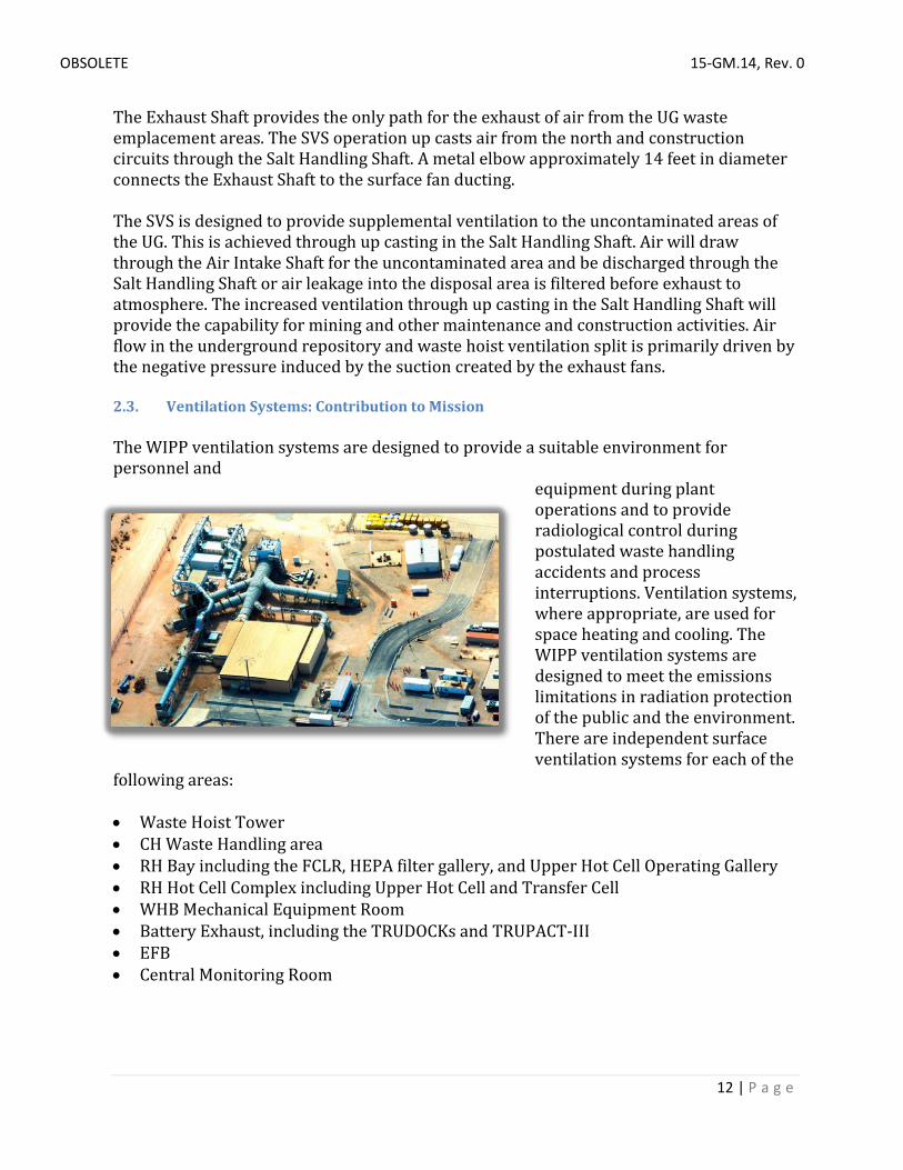
The Exhaust Shaft provides the only path for the exhaust of air from the UG waste emplacement areas. The SVS operation up casts air from the north and construction circuits through the Salt Handling Shaft. A metal elbow approximately 14 feet in diameter connects the Exhaust Shaft to the surface fan ducting. The SVS is designed to provide supplemental ventilation to the uncontaminated areas of the UG. This is achieved through up casting in the Salt Handling Shaft. Air will draw through the Air Intake Shaft for the uncontaminated area and be discharged through the Salt Handling Shaft or air leakage into the disposal area is filtered before exhaust to atmosphere. The increased ventilation through up casting in the Salt Handling Shaft will provide the capability for mining and other maintenance and construction activities. Air flow in the underground repository and waste hoist ventilation split is primarily driven by the negative pressure induced by the suction created by the exhaust fans. 2.3. Ventilation Systems: Contribution to Mission The WIPP ventilation systems are designed to provide a suitable environment for personnel and
equipment during plant operations and to provide radiological control during postulated waste handling accidents and process interruptions. Ventilation systems, where appropriate, are used for space heating and cooling. The WIPP ventilation systems are designed to meet the emissions limitations in radiation protection of the public and the environment. There are independent surface ventilation systems for each of the
following areas: • Waste Hoist Tower • CH Waste Handling area • RH Bay including the FCLR, HEPA filter gallery, and Upper Hot Cell Operating Gallery • RH Hot Cell Complex including Upper Hot Cell and Transfer Cell • WHB Mechanical Equipment Room • Battery Exhaust, including the TRUDOCKs and TRUPACT-III • EFB • Central Monitoring Room

OBSOLETE 15-GM.14, Rev. 0
13 | P a g e
The operation of the supply and exhaust fans for the WHB is controlled to maintain differential pressures between rooms. The WHB exhaust fans and controls can be supplied by backup power in the event that normal power is interrupted. 2.4. Fire Protection System: Contribution to Mission The WIPP Fire Protection System is designed to ensure personnel safety, mission continuity and property conservation. Building designs incorporate features for fire prevention. The plant design meets the improved risk level of protection defined in DOE Order 420.1C, and satisfies applicable sections of the National Fire Protection Association (NFPA) codes, DOE orders, and federal codes described in the Fire Hazard Analysis (FHA) for the Waste Isolation Pilot Plant (WIPP-023). The WIPP Fire Protection System, as described in the Fire Protection System SDD (SDD FP00), consists of four subsystems:
• Fire water supply and distribution system • Fire detection and alarm system • Fire Suppression System • Radio fire alarm reporter system
2.5. Fire Water Supply and Distribution System: Contribution to Mission The fire water supply and distribution system consists of two fire pumps and a pressure maintenance (jockey) pump located in the water pump house and a compound-loop yard distribution system. One fire pump is electric-motor driven and the other pump is diesel-engine driven. Both pumps are rated for 1,500 gallons per minute (gpm) at 125 psi. The system’s maximum design flow rate is to provide fire water at a rate of 1,500 gpm for two hours, for a total of 180,000 gallons. All major components of the fire water supply and distribution system are listed by Underwriters’ Laboratories Inc. and/or approved by Factory Mutual Engineering Corporation. The fire water supply system receives its water supply from one onsite 180,000-gallon ground-level storage tank, which is part of the water distribution system. Operation of the two fire pumps and the jockey pump is controlled by distribution-system pressure changes. The pumps are arranged for sequential operation. Under normal conditions, the jockey pump operates to maintain the designed system static pressure. Should there be a demand for fire water that exceeds the capacity of the jockey pump, the fire water demand will cause the system pressure to drop, which automatically starts the electric fire pump. If the jockey and electric fire pumps cannot maintain system pressure, the diesel pump automatically starts. The yard compound-loop distribution system serves all areas of the site by supplying fire water to all facilities containing a sprinkler system and to the fire hydrants, located at approximately 300-foot intervals throughout the site. The system contains numerous sectionalizing and control valves that are locked open and visually checked monthly.

OBSOLETE 15-GM.14, Rev. 0
14 | P a g e
2.6. Water Use: Contribution to Mission Uses of surface or groundwater in the vicinity of the WIPP site include several windmills throughout the area to pump groundwater for livestock and several ponds to capture runoff for livestock. The WIPP fire and potable water are obtained via a 10-inch water pipeline managed by the city of Carlsbad. 2.7. Electrical System: Contribution to Mission The WIPP electrical system is designed to provide normal and backup power, grounding for electrically energized equipment and other plant structures, lightning protection for the plant, and illumination for the WIPP surface and UG. The WIPP has standard industrial electrical distribution equipment including the following:
• Medium-voltage switchgear and buses • Medium-voltage to low-voltage step-down unit substations • Motor control centers • Small distribution transformers and panels • Relay and protection circuitry • Station batteries and associated synchronous inverters • Two diesel generators
The WIPP site normal power is from a public utility company, which supplies electrical power from their 115-kV Potash/Kerrmac Junction transmission line from the north and Whitten/Jal substation line from the south. The north line is approximately nine miles long, while the south line is approximately 19 miles long. The Potash Junction and Whitten substations each have two feeders from multiple generating stations, and loss of one generating source does not interrupt power to the WIPP site. The utility substation at the WIPP site is located east of the PPA. Area substations are located at the various surface facilities. UG conduits, cable duct banks, and buried cables
connect the plant substation with the area substations. The central Uninterruptible Power Supply (UPS), located in the Support Building, provides transient free, reliable 120/208 volts of alternating current power to the essential loads. This ensures continuous power to the radiation detection system for airborne contamination and area radiation monitoring, local processing units, computer room and CMR even during the interval between the

OBSOLETE 15-GM.14, Rev. 0
15 | P a g e
loss of offsite power and initiation of backup diesel generator power. Additional UPSs provide transient free power to strategically located local processing units for the radiation monitoring system on the surface, in selected areas in the Exhaust Shaft, and in UG passages and waste disposal areas. In case of loss of alternating current power input to the UPSs, the dedicated batteries can supply power to a fully loaded UPS for 30 minutes.
2.8. Maintenance Program: Contribution to Mission A WIPP Maintenance Program is implemented to ensure that maintenance activities are conducted to preserve and restore the availability, operability, and reliability of the WIPP Safety Significant (SS) Structures, Systems and Components (SSCs) important to the operation of the facility. This includes SS SSCs; other systems that perform important defense-in-depth functions; equipment relied on for the safe operation, safe shutdown of the nuclear facility, and for maintaining the facility in a safe shutdown condition as documented in the safety basis (e.g., DSA); and safety support systems. Maintenance work activities are performed by the WIPP maintenance personnel or subcontractors in accordance with WP 10-WC3011, Work Control Process. Subcontracted activities are also specified in a statement of work. The maintenance organization, responsibilities, and interfaces are prescribed in the maintenance and work control procedure sets. Surface maintenance facilities include a mechanical shop, an electrical shop, and an area for instrumentation and control calibration. Measurement and test equipment and tools for specific jobs are checked out from a tool crib. There is also a maintenance shop in the north end of the UG for making equipment repairs. 2.9. Current Operating Conditions Most of WIPP’s essential structures, facilities and properties were constructed in the 1980s with many of them currently exceeding their design life and in need of extensive repairs or replacement in order for NWP to continue its mission. According to a May 2016 study, entitled “Real Property Condition Assessment Surveys,” conducted by Nelson Engineering Co., Merritt Island, FL, 57 percent of the WIPP structures, facilities and properties are substandard, meaning a majority of components of each have exceeded their design life. Fourteen percent of them were listed as

OBSOLETE 15-GM.14, Rev. 0
16 | P a g e
inadequate and only 29 percent of the current structures, facilities and properties inside the WIPP fence were adequate to continue service to the mission. The study also rated the system life of the structures, facilities and properties. It noted that currently 79 percent needed repair or replacement within the next year; six percent needed repair or replacement immediately; another six percent needed repair or replacement in the next one to two years; and nine percent needed replacement in the next three to five years. A report concerning ventilation configuration using the Salt Handling Shaft (SHS) was prepared in May 2016. The report detailed the current condition and lifespan of the SHS. There is currently observed evidence of corrosion on the shaft buntons and shaft liner (See Figure 14), however the actual amount of corrosion is difficult to quantify. It is likely that a portion of the head frame steel will require replacement after blasting has occurred but prior to painting the head frame. NWP Engineering believes the existing corrosion on the buntons can be managed by the WIPP Maintenance program. It is difficult to ascertain the length of time the shaft infrastructure can be maintained as operational without the requisite major repairs. Additionally, it is anticipated that such repairs could take the shaft out of service for between 52 and 78 weeks. It is estimated that repairs should take place within the next 5 years. Delays in the proposed refurbishment beyond 5 years could result in the need to completely replace the Salt Hoist head frame and the collar. In summary, in order for NWP to safely continue the mission of emplacing the nation’s TRU waste from restart of operations in December 2016 until mission completion in 2050, substantial repairs or replacements of existing structures, facilities and properties are needed within the next five years. 3. Approach This Strategic Plan is intended to meet an overall objective of safe and compliant emplacement of legacy and newly generated waste through 2050 in a way that is efficient, cost effective and consistent with DOE priorities and strategies.
The approach used to understand WIPP’s waste emplacement capability was the development of a process model and simulation based on historical data, engineering analysis, and a clear set of assumptions that were vetted through a diverse project team. The team was made up of cognizant managers, supervisors and engineers, including NWP and CBFO stakeholders. The resulting

OBSOLETE 15-GM.14, Rev. 0
17 | P a g e
emplacement rate represented a “normal” rate per shift given in nominal 7-pack equivalent units. The number of 7-pack equivalents was converted to shipments per week by using the assumption than on average, one shipment is made up of five 7-packs (this based on historical averages). The results gave a realistic estimation of WIPP’s waste emplacement capabilities. In parallel to determining an emplacement rate, the number of available operational waste emplacement days (or shifts) was estimated, considering planned and unplanned maintenance, outages, holidays, and plant project impacts. These emplacement impacts were grouped by fiscal year so that they may be considered with the emplacement rate in order to determine what shipping rates and disposal volumes will look like. This Strategic Plan will be updated annually to align with the latest progress and future strategy. The target for the updates will be in the January to March timeframe to coincide with the Federal budget cycle. The model/simulation software will serve as an input to a WIPP Strategic Plan. The plan will continue to align with other strategic efforts and serve as a roadmap for WIPP’s lifecycle operations through 2050. A WIPP Strategic Plan Schedule will be generated and updated as needed to communicate the interrelation of plant projects, mining, disposal operations, and other key constraints, by utilizing planning tools including the Simio model simulation software, spreadsheets and system planning tools. Simio Design Edition was selected as the software package to model and simulate WIPP’s waste handling operations. Simio Design Edition is a modeling and simulation software package that translates the complexity of a real world operation into a computer process system allowing dynamic analysis on the system much faster than in real time. The model/simulator provides stakeholders with a platform to perform rapid analysis of what-if scenarios and determine likely outcomes. Bottlenecks and process pinch points are quickly identified. The Simio software is released by Simio LLC, who is widely recognized as an industry leader in simulation software. 4. Summary and Results The following summary will outline the recommended path forward for operation through FY50. 4.1. Waste Emplacement Rate Model simulations were used to estimate emplacement rates for contaminated and non-contaminated operations.

OBSOLETE 15-GM.14, Rev. 0
18 | P a g e
4.1.1. Contaminated Waste Emplacement Rate The waste handling process can be broken down into a surface operation, a hoisting operation, and an underground operation. Once the entire process was modeled, it became apparent that given its radiological contamination constraints, the underground operation emerged as the primary limitation to the overall waste emplacement operation. Underground ventilation, while a vital requirement to the waste emplacement operation, is either sufficient to operate, or not. Adding more ventilation alone, does not impact the rate in which waste can be emplaced. What became obvious was the fact that the key to maximizing the amount of waste that can be emplaced is to maximize the amount of time in a shift that waste is physically being moved (production time), and to maximize the number of available shifts to operate. Production time has many definitions, but for the purposes of estimating waste emplacement rate, it is the time that the operators are physically managing TRU waste. Other time within a shift is occupied by pre/post job meetings, area preparation and planning, donning/doffing personal protective equipment, movement of non-waste material, breaks/lunch, etc. The amount of production time has been estimated and is included in the assumption list (see Description of Assumptions and Bases, Section 4.3.2). A productivity factor of 2x was applied to the contaminated operations, meaning all process times for steps performed in contaminated areas were doubled. The basis for this factor is the experience with contaminated bolting operations as well as experience at other DOE sites performing contaminated operations. Given the assumptions, Table 1 represents the anticipated waste emplacement rate organized by fiscal year. The base emplacement rate supported by the model and analysis is 4.8 shipments per week.

OBSOLETE 15-GM.14, Rev. 0
19 | P a g e
Table 1. CH Contaminated Emplacement Rate
The hatched area shown in Table 1 on top of the base emplacement rate represents management’s estimate of process improvement and efficiencies attained and implemented over time. By FY18, it is estimated that operations will be capable of emplacing 7.2 CH shipments per week, and up to 9.6 CH shipments per week by FY19. At those emplacement rates, it is forecast that Panel 7 will be filled in FY22. Emplacement rates could increase should the radiological conditions improve. A sensitivity analysis was performed, and indicated that it will require a 30% increase in time performing waste emplacement in order to step to the next rate level, specifically 7.2 shipments per week. Management will consider shift durations and other potential alternative operational approaches in order to increase the emplacement rate without compromising safety and compliance. The emplacement rates in Table 1 represent how much CH waste that WIPP can emplace when available to operate. When emplacement operations are impacted by projects, planned and unplanned maintenance, etc., the emplacement rate is zero. In order to understand the quantity of waste that WIPP is capable of emplacing, the rate must be coupled with the available operational shifts (see Availability, Section 4.2). 4.1.2. Non-Contaminated Waste Emplacement Rate The non-contaminated waste emplacement rate is predicted at 12 shipments per week. Non-contaminated operations will benefit from not dealing with existing radiological controls. This prediction does not account for future process efficiencies discovered in optimization efforts for contaminated operations.

OBSOLETE 15-GM.14, Rev. 0
20 | P a g e
There may be an expectation for non-contaminated emplacement rates to be 17 shipments per week like they were prior to the 2014 events, instead of the model predicted 12. This is not the case due to a number of factors such as the additional controls required by the new DSA that add time to the surface and underground process in order to implement. It will be a management challenge to find efficiencies and alternative operational approaches to increase the emplacement rate without compromising safety and compliance. As appropriate, the model for non-contaminated operations will be kept in sync with the contaminated operations as well as validated once non-contaminated operations is available. 4.2. Availability Available operational shifts are estimated by fiscal year considering planned and unplanned maintenance, outages, holidays, and plant project impacts. These types of activities do not directly affect the rate that waste is emplaced, however, they directly impact how many shifts can be worked in a given time. Table 2 shows annually recurring impacts to waste emplacement. These recurring impacts account for 118 days (shifts) every fiscal year until PVS comes online in FY21.
Table 2. Common activities impacting waste emplacement
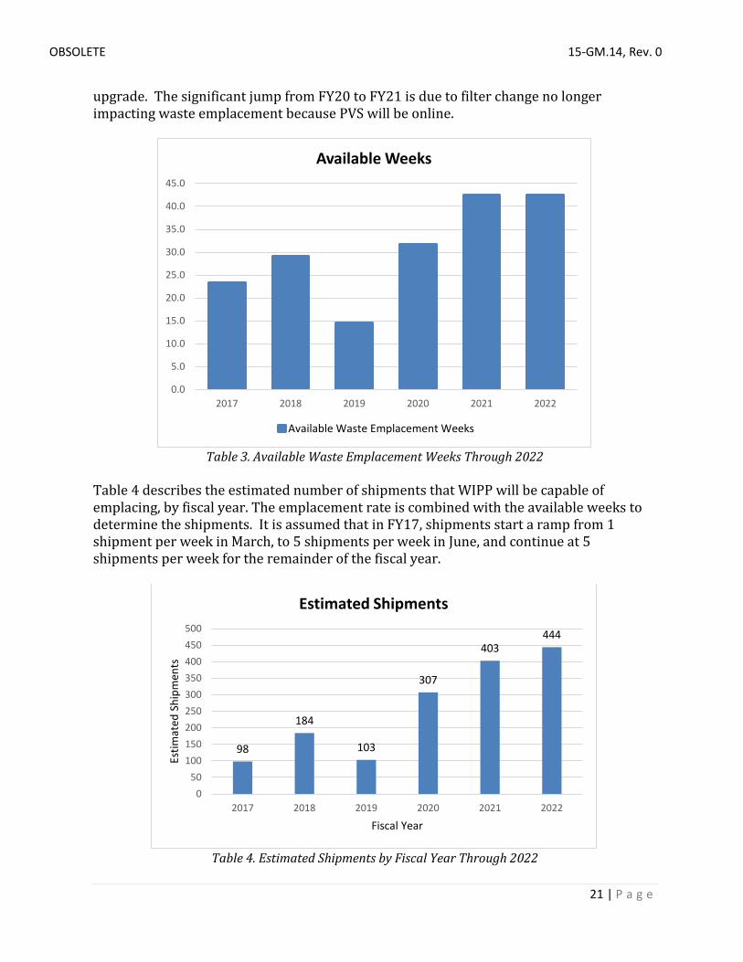
Plant project activities that impact emplacement due to tie-in requirements or other impactive activities were collected by fiscal year. These project impacts coupled with the recurring annual impacts result in a total waste emplacement impact basis by fiscal year. Table 3 describes the number of weeks that the facility is predicted to be capable of emplacing waste. In FY17, it is assumed that there will not be a long outage. The significant reduction of available weeks in FY19 is due to the waste hoist controller
36%
10%
3%
34%
17%
Common activities impacting waste emplacement
Annual Outages (7 weeks) Restorative Maintenance (Unplanned)
Holidays Not During Outage Replace MOD Filters (Mining)
Replace High Eff Filters (Mining)
OBSOLETE 15-GM.14, Rev. 0
21 | P a g e
upgrade. The significant jump from FY20 to FY21 is due to filter change no longer impacting waste emplacement because PVS will be online.
Table 3. Available Waste Emplacement Weeks Through 2022
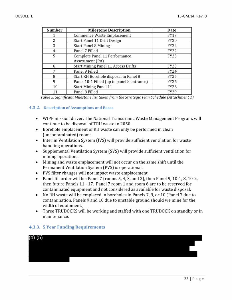
Table 4 describes the estimated number of shipments that WIPP will be capable of emplacing, by fiscal year. The emplacement rate is combined with the available weeks to determine the shipments. It is assumed that in FY17, shipments start a ramp from 1 shipment per week in March, to 5 shipments per week in June, and continue at 5 shipments per week for the remainder of the fiscal year.
Table 4. Estimated Shipments by Fiscal Year Through 2022
0.0
5.0
10.0
15.0
20.0
25.0
30.0
35.0
40.0
45.0
2017 2018 2019 2020 2021 2022
Available Weeks
Available Waste Emplacement Weeks
98
184
103
307
403444
050
100150200250300350400450500
2017 2018 2019 2020 2021 2022
Estim
ated
Shi
pmen
ts
Fiscal Year
Estimated Shipments

OBSOLETE 15-GM.14, Rev. 0
22 | P a g e
The RH TRU process is not being authorized under Revision 5b of the Documented Safety Analysis (DSA) as this activity will not be implemented as part of CH waste emplacement restart. Assumptions about future RH waste emplacement were based on SME historical knowledge of the RH borehole waste disposal process. At the November 2015 meeting of the National TRU Waste Corporate Board, an RH Working Group was started to investigate alternative RH disposal methods. The group will identify alternative methods to package, transport, and dispose of RH waste at WIPP without using boreholes, considering short term and long term strategies. As of the writing of this document, the RH Working Group has yet to release a report on alternative RH disposal methods. RH emplacement rates through 2021 are projected as 0. No RH will be emplaced in bore holes in Panels 7, 9 or 10; Panel 7 because of the radiological contamination and Panel 9 and 10 because they are drift panels not designed for RH disposal equipment. Should radiological contamination conditions change (improve), RH emplacement may be possible sooner. Use of Shielded Containers is an available method of RH disposal, and considered equivalent to CH disposal. 4.3. WIPP Recommended Path Forward 4.3.1. Summary In order to maximize WIPP’s waste storage capacity, panels 9 and 10 should be used for waste emplacement. There are unresolved questions related to whether or not panels 9 and 10 will be suitable (safe) for waste emplacement given the deteriorated condition of the mine in that location. A ground control conditions report was issued in February 2016 that indicated that supplemental bolting will become ineffective at controlling roof conditions, and a plan for long-term remediation is needed. The recommended path forward is to utilize panels 9 and 10 for waste emplacement, however if that is not a safe and compliant option, an alternative approach is described in the alternative analysis section. There are many interrelated factors and open decisions involved with the use of panels 9 and 10 for waste disposal, permanent panel closure of interim closed panels, and where to place/store mined salt. It is recommended that a stakeholder/decision maker workshop, working group, or integrated project team be chartered to work through the various options and document a decision for the best path forward. The WIPP Strategic Plan Schedule (Attachment 1) was developed to communicate the interrelation of plant projects, mining, disposal operations, permit actions, and other key constraints in order to serve as a roadmap for WIPP’s lifecycle operations through 2050. Table 5 lists the significant milestones reflected on the Strategic Plan Schedule.
OBSOLETE 15-GM.14, Rev. 0
23 | P a g e
Number Milestone Description Date 1 Commence Waste Emplacement FY17 2 Start Panel 11 Drift Design FY20 3 Start Panel 8 Mining FY22 4 Panel 7 Filled FY22 5 Complete Panel 11 Performance
Assessment (PA) FY23
6 Start Mining Panel 11 Access Drifts FY23 7 Panel 9 Filled FY24 8 Start RH Borehole disposal in Panel 8 FY25 9 Panel 10-1 Filled (up to panel 8 entrance) FY26 10 Start Mining Panel 11 FY26 11 Panel 8 Filled FY29
Table 5. Significant Milestone list taken from the Strategic Plan Schedule (Attachment 1) 4.3.2. Description of Assumptions and Bases
• WIPP mission driver, The National Transuranic Waste Management Program, will continue to be disposal of TRU waste to 2050.
• Borehole emplacement of RH waste can only be performed in clean (uncontaminated) rooms.
• Interim Ventilation System (IVS) will provide sufficient ventilation for waste handling operations.
• Supplemental Ventilation System (SVS) will provide sufficient ventilation for mining operations.
• Mining and waste emplacement will not occur on the same shift until the Permanent Ventilation System (PVS) is operational.
• PVS filter changes will not impact waste emplacement. • Panel fill order will be: Panel 7 (rooms 5, 4, 3, and 2), then Panel 9, 10-1, 8, 10-2,
then future Panels 11 - 17. Panel 7 room 1 and room 6 are to be reserved for contaminated equipment and not considered as available for waste disposal.
• No RH waste will be emplaced in boreholes in Panels 7, 9, or 10 (Panel 7 due to contamination. Panels 9 and 10 due to unstable ground should we mine for the width of equipment.)
• Three TRUDOCKS will be working and staffed with one TRUDOCK on standby or in maintenance.
4.3.3. 5 Year Funding Requirements
(b) (5)

OBSOLETE 15-GM.14, Rev. 0
24 | P a g e
4.4. Alternative Analysis: No Emplacement in Panels 9 and 10 4.4.1. Summary The recommended path forward is to utilize panels 9 and 10 for waste emplacement, however if that is not a safe and compliant option, an alternative approach is to not use panels 9 and 10 for waste emplacement, and proceed straight to Panel 8 after filling Panel 7. This alternative leaves empty disposal space and does not maximize WIPP’s available waste disposal capacity. However, it will accelerate the availability of disposal space for bore hole emplaced RH. This alternative will detail the mining of additional panels that will be necessary to complete the WIPP mission. Modifying the panel fill order allows for borehole emplaced RH to be disposed of sooner. Not using Panels 9 and 10 for disposal mitigates the known risk related to ground control concerns at the south end of the mine. This alternative does not maximize use of currently available disposal areas. It accelerates the need for mining new disposal panels, which leads to increased risk being placed on mining operations meeting schedules.
(b) (5)

OBSOLETE 15-GM.14, Rev. 0
25 | P a g e
WIPP Strategic Plan – Alternative Schedule (Attachment 2) was developed to communicate the interrelation of plant projects, mining, disposal operations, permit actions, and other key constraints in order to represent this alternative approach and understand the associated impacts. Several risks and accelerated timelines were exposed by modeling this alternative:
• Concurrent mining of Panel 8 and Panel 11 Drifts will be required • Panel 11 Drift mining delays – If Panel 11 mining is delayed, then there could be a
period where WIPP would have no disposal capacity availability, which would interrupt the mission.
• This alternative removes any chance to construct the new exhaust shaft using the bottom-up method due to more urgent need for Panel 8 and the Panel 11 Drifts.
• Work on the Panel 11 Drifts design, performance assessment, and permitting process would be greatly accelerated and require action as soon as FY18.
Amongst the risks associated with the alternative to not utilize Panels 9 and 10 for disposal, it should be mentioned that should decontamination efforts in Panel 7 and/or panels 9 and 10 prove successful, the emplacement rates used to determine when the next panels are needed will change, invalidating the current plan. It is recommended that should effort be directed to decontaminate panel 7, that scenario be modeled and a Strategic Plan Schedule be generated in order to fully understand the impacts. 4.4.2. Funding: The funding profile for this alternative does not vary greatly from the preferred alternative. By not maximizing WIPP’s available waste disposal capacity however, the mission life could be extended, which would add to the lifecycle cost of WIPP. 4.5. Regulatory Drivers U.S. Environmental Protection Agency On May 18, 1998, the EPA certified the WIPP as the nation’s first geologic repository for the disposal of transuranic (TRU) wastes generated by atomic energy defense activities. The EPA next recertified the WIPP’s continuing compliance with the disposal regulations, 40 CFR Part 191, Subparts B and C on March 29, 2006. The submittal of a recertification application for the WIPP is required by Section 8(f) of the WIPP Land Withdrawal Act (LWA) to occur not later than five years after initial receipt of TRU waste for disposal at the repository, and every five years thereafter until the decommissioning of the facility is completed. The first recertification application was submitted on March 26, 2004. The EPA has the authority to regulate the radiological aspects of the waste at WIPP by certification through EPA’s Radiation Protection Program. EPA issued its second recertification decision for WIPP on November 18, 2010. EPA determined that the DOE WIPP facility continues to comply with the agency's waste disposal regulations and compliance criteria. Under this program, before DOE can dispose of waste at the WIPP, it must demonstrate that the waste has been characterized in compliance with the EPA

OBSOLETE 15-GM.14, Rev. 0
26 | P a g e
regulations at 40 CFR 194 and meets EPA's radioactive waste disposal standards (40 CFR 191). New Mexico Environmental Department The New Mexico Environmental Department (NMED) is responsible for monitoring and controlling the generation, storage, transportation, and disposal of wastes in New Mexico. NMED is responsible for providing the highest quality of life throughout the state by promoting a safe, clean, and productive environment. On Oct. 27, 1999, the NMED issued a final decision to grant a Hazardous Waste Facility Permit to the DOE for the storage and disposal of transuranic mixed waste. DOE mixed transuranic waste (MTRU) is waste that has a hazardous component and radioactive elements heavier than uranium. Since shipments began in 1999, over 90,000 cubic meters of waste though nearly 12,000 shipments has been emplaced at WIPP. NMED provides regulatory oversight of the hazardous waste facility permit to ensure compliance which includes review and issuance of permit modifications, and observation, review and approval of generator site audits. A dual regulatory framework exists for mixed-waste. The State of New Mexico's authority to regulate the hazardous waste at WIPP is governed under the New Mexico Hazardous Waste Act (HWA) and the Resource Conservation and Recovery Act (RCRA). Under RCRA, the State of New Mexico is authorized to operate in lieu of the Environmental Protection Agency (EPA); EPA does not regulate mixed wastes in those States with an authorized program. New Mexico is authorized by EPA under 50 Fed Reg 1515 (January 11, 1985). New Mexico implements this authority under the HWA, NMSA 1978, §74-4-1 et seq (Repl. Pamp. 2000). Other Regulatory Drivers NWP also adheres to numerous Federal and state of New Mexico requirements and regulations, such as the National Environmental Policy Act, Federal Regulations (40 CFR Part 191 and 40 CFR Part 194) and the National TRU Waste Management Plan.
4.6 Strategic Alignment
The success of DOE’s mission to safely and permanently dispose of TRU and TRU mixed wastes from the nation’s Cold War defense weapons production program is a result of a strategic alignment fostered over the years between DOE, NWP, the generator sites in the National TRU Waste program and all regulatory stakeholders. This Strategic Plan utilizes as resources strategic plans from DOE and CBFO as well as from Los Alamos National Laboratory – Carlsbad office and Sandia National Laboratory – Carlsbad office.

OBSOLETE 15-GM.14, Rev. 0
27 | P a g e
4.6.1 National TRU Waste Management Plan The National TRU Waste Management Plan (NTWMP), DOE/NTP 96-1204, provides a National TRU Program (NTP) strategy that is integrated, compliant, and includes a tactical approach for the disposition of TRU wastes. The CBFO NTP office coordinates with DOE Headquarters and DOE Field Offices to integrate the various TRU waste clean-up efforts taking place across the DOE complex. This includes TRU waste inventory, characterization, certification, transportation, packaging, disposal, technical support, and regulatory interface. The NTWMP approach for planning and executing complex-wide management of radioactive waste ensures the CBFO and the generator site waste management programs are integrated and the requirements of DOE Order 435.1, Radioactive Waste Management, are met. A National Transuranic Waste Corporate Board, which was founded in May 2001, serves as a consensus-building and advisory body to the DOE Assistant Secretary for Environmental Management (EM-1), and assists with the integration of CBFO goals and NTWMP objectives with generator sites across the complex. This strategic plan will receive input from the NTWMP and that input will serve as a basis for near and long term planning. 4.6.2 WIPP FY2016 to FY2026 Ten-Year Site Plan The WIPP Ten-Year Site Plan, DOE/WIPP 04-3327, provides information on site facilities and infrastructure planning requirements, assumptions and targets, real property asset management, including financial planning, and site facilities and infrastructure management and investment for the next ten years. This Strategic Plan will provide input to and align with the WIPP Ten-Year Site Plan, which incorporates input from the Material Condition and Aging Management Plan, Annual System Health Reports, Condition Assessment Surveys, and other inputs related to plant maintenance and infrastructure needs. 4.6.3 FY2018 NWP Integrated Priority List An Integrated Priority List (IPL) reflects future program funding needs and identified project funding targets. This strategic plan will provide input to and align with future IPLs as they are developed, as well integrate with the Material Condition and Aging Management Plan and the Facility Information Management System to consider improvement needs, ensuring long term stewardship of WIPP.

OBSOLETE 15-GM.14, Rev. 0
28 | P a g e
4.6.4 CBFO Strategic Plan The CBFO Strategic Plan, DOE/CBFO 11-3473, discusses CBFO’s responsibility for the WIPP and the National TRU Program. The office's mission is to provide safe, compliant, and efficient characterization, transportation, and disposal of defense-related TRU wastes. Its vision is to enable a nuclear future for our country by providing safe and environmentally responsible waste management. This plan will provide input to and align with CBFO’s priorities and goals described in CBFO’s Strategic Plan. 5 Quality Assurance and Risk Management
5.1 Quality Assurance Software Quality Assurance was implemented for the model by applying procedure WP 16-2, Rev. 15 Software Screening and Control Management Control Procedure. The procedure dictates that all software that is acquired, received, or developed by or for NWP shall be screened according the Software Screening Checklist. Software Screening Checklist EA 16-2-1-0, Rev. 6, was completed and Simio Simulations and Scheduling Software were determined to be “Not-Controlled” and, therefore, not subject to additional quality assurance screening requirements. A time motion study will be conducted during cold operations/initial operation as part of the restart activities in order to validate the model. A validation plan is currently in development. 5.2 Risk Management DOE/WIPP 05-3549, Waste Isolation Pilot Plant Risk and Opportunity Management Plan (ROMP), documents the comprehensive identification and analysis of technical risks and opportunities associated with the WIPP mission. It identifies the individual technical and programmatic risks, and presents the strategies for handling risks and opportunities in the near-term and out-years. 6 Future Considerations In light of the Obama administration’s FY17 budget request cancelling the Mixed Oxide Fuel Fabrication Facility, commonly known as MOX, located in South Carolina,

OBSOLETE 15-GM.14, Rev. 0
29 | P a g e
considerable discussion has been on-going about accommodating 34 metric tons of plutonium at WIPP. The administration’s current approach to rid the nation of its plutonium stockpile and to adhere to a U.S. treaty with Russia, is called dilute and dispose. The plutonium will be chemically diluted into a form that can be safely disposed at WIPP. WIPP would accommodate that waste inventory as any other TRU waste stream in the TRU waste inventory. No decision has been made at this time on the 34 metric tons of plutonium currently in the nation’s nuclear stockpile. However, the administration has approved the shipment of 6.6 tons of plutonium, or approximately 4,000 cubic meters of waste once diluted and packaged, from South Carolina to WIPP for future emplacement.
In order to enable WIPP to dispose of the 34 metric tons of plutonium and other not yet identified potential TRU waste streams, it may be necessary to change the method of accounting for disposed waste volumes to a more accurate inner container volume method. This change will reduce the risk of reaching WIPP’s waste volume limit as describe in the Land Withdrawal Act.
7 References
40 CFR 191, “Environmental Radiation Protection Standards for Management and Disposal of Spent Nuclear Fuel, High-Level and Transuranic Wastes,” Subpart A, “Environmental Standards for Management and Storage,” Code of Federal Regulations. U.S. Government Printing Office, Washington, DC.
40 CFR 191, “Environmental Radiation Protection Standards for Management and Disposal of Spent Nuclear Fuel, High-Level and Transuranic Radioactive Wastes,” Section 191.14, “Assurance Requirements,” Paragraph (d), Code of Federal Regulations. U.S. Government Printing Office, Washington, DC.
40 CFR 194, “Criteria for the Certification and Re-Certification of the Waste Isolation Pilot Plant’s Compliance with The 40 CFR Part 191 Disposal Regulations,” Section 194.44, “Engineered Barriers,” Code of Federal Regulations. U.S. Government Printing Office, Washington, DC.
DOE Order 420.1C, Change 1, Facility Safety, February 27, 2015, U.S. Department of Energy, Washington, DC.
DOE Order 430.1B, Real Property Asset Management, April 25, 2011, U.S. Department of Energy, Washington, DC.
DOE Order 435.1, Change 1, Radioactive Waste Management, January 9, 2007, U.S. Department of Energy, Washington, DC.
DOE/CBFO, FY18 Integrated Priority List, U.S. Department of Energy, CBFO, Carlsbad, NM.

OBSOLETE 15-GM.14, Rev. 0
30 | P a g e
DOE/CBFO 11-3473, Carlsbad Field Office Strategic Plan Rev. 0, U.S. Department of Energy, Carlsbad Field Office, Carlsbad, NM.
DOE/WIPP 04-3327, Waste Isolation Pilot Plant Ten-Year Site Plan FY 2017 – FY 2026 Revision 12, U.S. Department of Energy, Carlsbad Field Office, Carlsbad, NM.
DOE/WIPP 05-3549, Waste Isolation Pilot Plant Risk and Opportunity Management Plan Rev. 0, U.S. Department of Energy, Carlsbad Field Office, Carlsbad, NM.
DOE/WIPP 07-3372, Waste Isolation Pilot Plant Documented Safety Analysis Rev. 5b, U.S. Department of Energy, Carlsbad Field Office, Carlsbad, NM.
DOE/NTP 96-1204, National TRU Waste Management Plan, Revision 3, July 2002, U.S. Department of Energy, Carlsbad Field Office, Carlsbad, NM.
Hazardous Waste Facility Permit, EPA Identification Number NM4890139088-TSDF
Nelson Engineering CO. (2016). Real Property Condition Assessment Surveys. Merrit Island, FL.
Nuclear Waste Partnership LLC. (2014). WP 16-2, Software Screening and Control Rev. 14. Carlsbad, NM.
Nuclear Waste Partnership LLC. (October 2015). WP 04-GC.08 Facilities Information Management System Improvement Plan Rev. 0. Carlsbad, NM.
Nuclear Waste Partnership LLC. (January 2016). WP 04-GC.09 Waste Isolation Pilot Plant Material Condition Aging Management Plan Rev. 0. Carlsbad, NM.
Public Law 102-579, 106 Stat. 4777, 1992 (as amended by Public Law 104-201, 1996), Waste Isolation Pilot Plant Land Withdrawal Act.
SDD FP00, Fire Protection System (FP00) System Design Description (SDD), Nuclear Waste Partnership LLC, Carlsbad, NM.
Report RSI-2597, February 2016 Inspection of WIPP Ground-Control Conditions and Related Activities, RESPEC, Rapid City, SD
U.S. Department of Energy Accident Fire Forensic Analysis of the Radiological Release Event at the Waste Isolation Pilot Plant on February 14, 2014, U.S. Department of Energy, Washington, DC.
U.S. Department of Energy Accident Investigation Report, Underground Salt Haul Truck Fire at the Waste Isolation Pilot Plant, February 5, 2014, U.S. Department of Energy, Washington, DC.
Whisenhunt, R. L., & Siepel, N. (2016). Salt Handling Shaft (SHS) Physical Concerns And the Anticipated Use of the SHS as an Upcasting Exhust Shaft with an Operationsl Supplemental Ventilation System (SVS) Report, Rev 1. Carlsbad, NM: Nuclear Waste Partnership, LLC
WP 10-WC3011, Work Control Process, Procedure, Nuclear Waste Partnership LLC, Carlsbad, NM

15-GM.14 Attachment 1FY16 FY17 FY18 FY19 FY20
1Q 2Q 3Q 4Q 1Q 2Q 3Q 4Q 1Q 2Q 3Q 4Q 1Q 2Q 3Q 4Q
Oct Nov Dec Jan Feb Mar Apr May Jun Jul Aug Sep Oct Nov Dec Jan Feb Mar Apr May Jun Jul Aug Sep Oct Nov Dec Jan Feb Mar Apr May Jun Jul Aug Sep Oct Nov Dec Jan Feb Mar Apr May Jun Jul
Permanent Ventilation System
114 KCFM
184 KCFM
Salt Hoist Controller Upgrade
CH P7 Rm 5Commence Waste Emplacement
CH P7 Rm 4
20
17
15
109 shipments/Wk
5 7 shipments/Wk1 5 shipments/Wk
50
40
30 29 weeks23 weeks
20
10 15 weeks1
Oct Nov Dec Jan Feb Mar Apr May Jun Jul Aug Sep Oct Nov Dec Jan Feb Mar Apr May Jun Jul Aug Sep Oct Nov Dec Jan Feb Mar Apr May Jun Jul Aug Sep Oct Nov Dec Jan Feb Mar Apr May Jun Jul
FY16 FY17 FY18 FY19 FY20
Panel Closure Design
Additional TRU Mixed Waste Storage CapacityEPA Recertification
Mine Maintenance
WIP
P S
trate
gic
Pla
n S
chedule
Rev.
0
Em
pla
cem
ent
Rate
s
Min
ing
Em
pla
cem
ent
Underg
round O
ps
Pro
jects
Em
pla
cem
ent
Availabilit
y
Printed
Perm
itti
ng
Acti
ons
Shif
ts/C
rew
sInterim Ventilation
P7 Waste Emplacement - 2 crews 6 shifts/Wk
Mine Maintenance
6/23/2016
*Not Shown - Rate is 0 during outages and
other emplacement impacting activities
There will be intermittent mining availability
during the Salt Hoist Upgrade
There will be intermittent emplacement
availability during the Waste Hoist
Upgrade
Supplemental Ventilation System
General Plant Projects - Fire Control System / Sitewide Electrical Infrastructure Upgrades (Switch Station / Generators / Reliability Upgrades)
Waste Hoist Controller
Refurbish Salt & AIS Shaft
Above Ground Storage
High Pressure Fire Loop (HPFL) / Surface Fire Water Distribution
1
OBSOLETE

FY19 FY20 FY21 FY22 FY23 FY24 FY254Q 1Q 2Q 3Q 4Q 1Q 2Q 3Q 4Q 1Q 2Q 3Q 4Q 1Q 2Q 3Q 4Q 1Q 2Q
Aug Sep Oct Nov Dec Jan Feb Mar Apr May Jun Jul Aug Sep Oct Nov Dec Jan Feb Mar Apr May Jun Jul Aug Sep Oct Nov Dec Jan Feb Mar Apr May Jun Jul Aug Sep Oct Nov Dec Jan Feb Mar Apr May Jun Jul Aug Sep Oct Nov
540 KCFM
CH P7 Rm 3 CH P9
CH P7 Rm 2
12 shipments/Wk
42 weeks
32 weeks
Aug Sep Oct Nov Dec Jan Feb Mar Apr May Jun Jul Aug Sep Oct Nov Dec Jan Feb Mar Apr May Jun Jul Aug Sep Oct Nov Dec Jan Feb Mar Apr May Jun Jul Aug Sep Oct Nov Dec Jan Feb Mar Apr May Jun Jul Aug Sep Oct Nov
FY19 FY20 FY21 FY22 FY23 FY24 FY25
General Plant Projects
Mine Panel 8-1 crews, 4 shifts/Wk
EPA Recertification
Mine Maintenance Mine Panel 11 Access Drifts
Panel 11 Access Drifts - 1 crews 4 shifts/Wk
Panel 9 Waste Emplacement 2 crews 6 shifts/Wk
Panel 9-2 crews, 6 shifts/Wk (after PVS)
P7 Waste Emplacement - 2 crews 6 shifts/Wk
Mine Maintenance
Mine Panel 8
P9 & P10 Prep MiningThere will be intermittent emplacement
availability during the Waste Hoist
Upgrade
General Plant Projects - Fire Control System / Sitewide Electrical Infrastructure Upgrades (Switch Station / Generators / Reliability Upgrades)
Panel 11 Drift Design
Waste Hoist Controller
Refurbish Salt & AIS Shaft
High Pressure Fire Loop (HPFL) / Surface Fire Water Distribution
Permanent Panel Closures
Panel 11 Performance Assessment
Panel 11 Permit Modification
2
5
4
3
6
OBSOLETE

FY24 FY25 FY26 FY27 FY28 FY291Q 2Q 3Q 4Q 1Q 2Q 3Q 4Q 1Q 2Q 3Q 4Q 1Q 2Q 3Q 4Q 1Q 2Q 3Q
Dec Jan Feb Mar Apr May Jun Jul Aug Sep Oct Nov Dec Jan Feb Mar Apr May Jun Jul Aug Sep Oct Nov Dec Jan Feb Mar Apr May Jun Jul Aug Sep Oct Nov Dec Jan Feb Mar Apr May Jun Jul Aug Sep Oct Nov Dec Jan Feb Mar
RH P8
CH P8
CH P10-1
RH P8
17 shipments/Wk
Dec Jan Feb Mar Apr May Jun Jul Aug Sep Oct Nov Dec Jan Feb Mar Apr May Jun Jul Aug Sep Oct Nov Dec Jan Feb Mar Apr May Jun Jul Aug Sep Oct Nov Dec Jan Feb Mar Apr May Jun Jul Aug Sep Oct Nov Dec Jan Feb Mar
FY24 FY25 FY26 FY27 FY28 FY29
General Plant Projects
Panel 10-1 Waste Emplacement 2 crew 6 shifts/Wk
Mine Panel 8-1 crews, 4 shifts/Wk
Panel 8 CH Waste Emplacement 2 crews 6 shifts/Wk
EPA Recertification
Mine Panel 11Mine Panel 11 Access Drifts
Mine Panel 11 - 1 crews, 4 shifts/Wk
Panel 11 Access Drifts - 1 crews 4 shifts/Wk
Panel 9 Waste Emplacement 2 crews 6 shifts/Wk Panel 8 RH Waste Emplacement 1 crew 4 shifts/Wk
Mine Panel 8
7
8
10
9
OBSOLETE

FY28 FY29 FY30 FY31 FY32 FY333Q 4Q 1Q 2Q 3Q 4Q 1Q 2Q 3Q 4Q 1Q 2Q 3Q 4Q 1Q 2Q 3Q 4Q
Apr May Jun Jul Aug Sep Oct Nov Dec Jan Feb Mar Apr May Jun Jul Aug Sep Oct Nov Dec Jan Feb Mar Apr May Jun Jul Aug Sep Oct Nov Dec Jan Feb Mar Apr May Jun Jul Aug Sep Oct Nov Dec Jan Feb Mar Apr May Jun Jul
CH P11
CH P10-2
RH P11
RH P12
Apr May Jun Jul Aug Sep Oct Nov Dec Jan Feb Mar Apr May Jun Jul Aug Sep Oct Nov Dec Jan Feb Mar Apr May Jun Jul Aug Sep Oct Nov Dec Jan Feb Mar Apr May Jun Jul Aug Sep Oct Nov Dec Jan Feb Mar Apr May Jun Jul
FY28 FY29 FY30 FY31 FY32 FY33
General Plant Projects
Mine DriftsMine Drifts
Mine Panel 12
EPA Recertification
Panel 8 CH Waste Emplacement 2 crews 6 shifts/Wk
Mine Drifts 6 shifts/wk
Mine Panel 11
Mine Panel 12 - 2 crews, 6 shifts/Wk
Mine Drifts 6 shifts/Wk
Mine Panel 11 - 1 crews, 4 shifts/Wk
Panel 10-2 CH - 6 shifts/WkPanel 11 CH Waste Emplacement 2 crews 6 shifts/Wk
Panel 11 RH Waste Emplacement 1 crew 4 shifts/WkPanel 12 RH Waste Emplacement 1 crew 4 shifts/Wk
11
OBSOLETE

FY32 FY33 FY34 FY35 FY36 FY37 FY384Q 1Q 2Q 3Q 4Q 1Q 2Q 3Q 4Q 1Q 2Q 3Q 4Q 1Q 2Q 3Q 4Q 1Q 2Q 3Q
Aug Sep Oct Nov Dec Jan Feb Mar Apr May Jun Jul Aug Sep Oct Nov Dec Jan Feb Mar Apr May Jun Jul Aug Sep Oct Nov Dec Jan Feb Mar Apr May Jun Jul Aug Sep Oct Nov Dec Jan Feb Mar Apr May Jun Jul Aug Sep Oct Nov Dec Jan Feb
CH P13
CH P12
RH P13
Aug Sep Oct Nov Dec Jan Feb Mar Apr May Jun Jul Aug Sep Oct Nov Dec Jan Feb Mar Apr May Jun Jul Aug Sep Oct Nov Dec Jan Feb Mar Apr May Jun Jul Aug Sep Oct Nov Dec Jan Feb Mar Apr May Jun Jul Aug Sep Oct Nov Dec Jan Feb
FY32 FY33 FY34 FY35 FY36 FY37 FY38
Mine Panel 14
General Plant Projects
Mine Drifts
Mine Panel 13 - 2 crews, 6 shifts/Wk
Panel 13 CH Waste Emplacement 2 crew 6 shifts/Wk
Mine Panel 14 - 2 crews, 6 shifts/WkMine Drifts 6 shifts/wk
Panel 11 CH Waste Emplacement 2 crews 6 shifts/Wk
Panel 12 RH Waste Emplacement 1 crew 4 shifts/Wk
Panel 12 CH Waste Emplacement 2 crew 6 shifts/Wk
Panel 13 RH Waste Emplacement 1 crew 4 shifts/Wk
Mine Panel 13
Waste Hoist Controller Upgrade
General Plant Projects
Salt Hoist Controller Upgrade
EPA Recertification
OBSOLETE

FY37 FY38 FY39 FY40 FY41 FY422Q 3Q 4Q 1Q 2Q 3Q 4Q 1Q 2Q 3Q 4Q 1Q 2Q 3Q 4Q 1Q 2Q 3Q 4Q 1Q
Mar Apr May Jun Jul Aug Sep Oct Nov Dec Jan Feb Mar Apr May Jun Jul Aug Sep Oct Nov Dec Jan Feb Mar Apr May Jun Jul Aug Sep Oct Nov Dec Jan Feb Mar Apr May Jun Jul Aug Sep Oct Nov Dec Jan Feb Mar Apr May Jun Jul Aug Sep Oct
CH P14
RH P15
RH P14
Mar Apr May Jun Jul Aug Sep Oct Nov Dec Jan Feb Mar Apr May Jun Jul Aug Sep Oct Nov Dec Jan Feb Mar Apr May Jun Jul Aug Sep Oct Nov Dec Jan Feb Mar Apr May Jun Jul Aug Sep Oct Nov Dec Jan Feb Mar Apr May Jun Jul Aug Sep Oct
FY37 FY38 FY39 FY40 FY41 FY42
Mine Panel 14 Mine Panel 15
General Plant Projects
Panel 15 RH Waste Emplacement 1 crew 4 shifts/Wk
Mine Drifts 6 shifts/wk
Mine Drifts Mine Drifts
Panel 14 RH Waste Emplacement 1 crew 4 shifts/Wk
Panel 13 CH Waste Emplacement 2 crew 6 shifts/Wk
Mine Panel 14 - 2 crews, 6 shifts/Wk Mine Panel 15 - 2 crews, 6 shifts/WkMine Drifts 6 shifts/wk
Panel 14 CH Waste Emplacement 2 crew 6 shifts/Wk
Panel 13 RH Waste Emplacement 1 crew 4 shifts/Wk
General Plant Projects
EPA Recertification
OBSOLETE

FY42 FY43 FY44 FY45 FY46 FY471Q 2Q 3Q 4Q 1Q 2Q 3Q 4Q 1Q 2Q 3Q 4Q 1Q 2Q 3Q 4Q 1Q 2Q 3Q 4Q
Nov Dec Jan Feb Mar Apr May Jun Jul Aug Sep Oct Nov Dec Jan Feb Mar Apr May Jun Jul Aug Sep Oct Nov Dec Jan Feb Mar Apr May Jun Jul Aug Sep Oct Nov Dec Jan Feb Mar Apr May Jun Jul Aug Sep Oct Nov Dec Jan Feb Mar Apr May Jun
CH P15
CH P16
RH P16
Nov Dec Jan Feb Mar Apr May Jun Jul Aug Sep Oct Nov Dec Jan Feb Mar Apr May Jun Jul Aug Sep Oct Nov Dec Jan Feb Mar Apr May Jun Jul Aug Sep Oct Nov Dec Jan Feb Mar Apr May Jun Jul Aug Sep Oct Nov Dec Jan Feb Mar Apr May Jun
FY42 FY43 FY44 FY45 FY46 FY47
Mine Panel 16 Mine Panel 17
General Plant Projects General Plant Projects
Panel 15 RH Waste Emplacement 1 crew 4 shifts/Wk
Mine Panel 16 - 2 crews, 6 shifts/Wk Mine Panel 17 - 2 crews, 6 shifts/WkMine Drifts 6 shifts/wk
Panel 16 CH Waste Emplacement 2 crew 6 shifts/Wk
Panel 16 RH Waste Emplacement 1 crew 4 shifts/Wk
Mine Drifts
Panel 15 CH Waste Emplacement 2 crew 6 shifts/Wk
Panel 14 CH Waste Emplacement 2 crew 6 shifts/Wk
EPA Recertification
OBSOLETE

FY46 FY47 FY48 FY49 FY504Q 1Q 2Q 3Q 4Q 1Q 2Q 3Q 4Q 1Q 2Q 3Q 4Q 1Q 2Q 3Q 4Q
Jul Aug Sep Oct Nov Dec Jan Feb Mar Apr May Jun Jul Aug Sep Oct Nov Dec Jan Feb Mar Apr May Jun Jul Aug Sep Oct Nov Dec Jan Feb Mar Apr May Jun Jul Aug Sep Oct Nov Dec Jan Feb Mar Apr May Jun Jul Aug Sep
CH P17
RH P17
Jul Aug Sep Oct Nov Dec Jan Feb Mar Apr May Jun Jul Aug Sep Oct Nov Dec Jan Feb Mar Apr May Jun Jul Aug Sep Oct Nov Dec Jan Feb Mar Apr May Jun Jul Aug Sep Oct Nov Dec Jan Feb Mar Apr May Jun Jul Aug Sep
FY46 FY47 FY48 FY49 FY50
Mine Panel 17
General Plant Projects
Mine Panel 17 - 2 crews, 6 shifts/Wk
Panel 16 CH Waste Emplacement 2 crew 6 shifts/Wk
Panel 16 RH Waste Emplacement 1 crew 4 shifts/Wk
Panel 17 CH Waste Emplacement 2 crew 6 shifts/Wk
Panel 17 RH Waste Emplacement 1 crew 4 shifts/Wk
OBSOLETE

15-GM.14 Attachment 2FY16 FY17 FY18 FY19 FY20
1Q 2Q 3Q 4Q 1Q 2Q 3Q 4Q 1Q 2Q 3Q 4Q 1Q 2Q 3Q 4Q
Oct Nov Dec Jan Feb Mar Apr May Jun Jul Aug Sep Oct Nov Dec Jan Feb Mar Apr May Jun Jul Aug Sep Oct Nov Dec Jan Feb Mar Apr May Jun Jul Aug Sep Oct Nov Dec Jan Feb Mar Apr May Jun Jul
Permanent Ventilation System
114 KCFM
184 KCFM
Salt Hoist Controller Upgrade
CH P7 Rm 5Commence Waste Emplacement
CH P7 Rm 4
20
17
15
109 shipments/Wk
5 7 shipments/Wk1 5 shipments/Wk
50
40
30 29 weeks23 weeks
20
10 15 weeks1
Oct Nov Dec Jan Feb Mar Apr May Jun Jul Aug Sep Oct Nov Dec Jan Feb Mar Apr May Jun Jul Aug Sep Oct Nov Dec Jan Feb Mar Apr May Jun Jul Aug Sep Oct Nov Dec Jan Feb Mar Apr May Jun Jul
FY16 FY17 FY18 FY19 FY20
P7 Waste Emplacement - 2 crews 6 shifts/Wk
Perm
itti
ng
Acti
ons
General Plant Projects - Surface Fire Water Distribution / Fire Control System / Sitewide Electrical Infrastructure Upgrades (Switch Station / Generators / Reliability Upgrades)
Interim Ventilation
Supplemental Ventilation System
Above Ground Storage
High Pressure Fire Loop (HPFL)
Refurbish Salt & AIS Shaft
Waste Hoist Controller
EPA Recertification
Panel 11 Drift Design
Panel 11 Performance Assessment
Mine Panel 8 - 1 crews, 4 shifts/Wk
WIP
P S
trate
gic
Pla
n -
Alt
ern
ati
ve S
chedule
Rev.
0
Em
pla
cem
ent
Rate
s
Min
ing
Em
pla
cem
ent
Underg
round O
ps
Pro
jects
Em
pla
cem
ent
Availabilit
y
Printed
Shif
ts/C
rew
s
There will be intermittent emplacement
availability during the Waste Hoist
Upgrade
Mine Panel 8
6/23/2016
*Not Shown - Rate is 0 during outages and
other emplacement impacting activities
There will be intermittent mining availability
during the Salt Hoist Upgrade
Panel Closure Design
Additional TRU Mixed Waste Storage Capacity Panel 11 Permit Modification
OBSOLETE

FY19 FY20 FY21 FY22 FY23 FY24 FY254Q 1Q 2Q 3Q 4Q 1Q 2Q 3Q 4Q 1Q 2Q 3Q 4Q 1Q 2Q 3Q 4Q 1Q 2Q
Aug Sep Oct Nov Dec Jan Feb Mar Apr May Jun Jul Aug Sep Oct Nov Dec Jan Feb Mar Apr May Jun Jul Aug Sep Oct Nov Dec Jan Feb Mar Apr May Jun Jul Aug Sep Oct Nov Dec Jan Feb Mar Apr May Jun Jul Aug Sep Oct Nov
540 KCFM
RH P8
CH P7 Rm 3 CH P8
CH P7 Rm 2
RH P8
17 shipments/Wk
42 weeks
32 weeks
Aug Sep Oct Nov Dec Jan Feb Mar Apr May Jun Jul Aug Sep Oct Nov Dec Jan Feb Mar Apr May Jun Jul Aug Sep Oct Nov Dec Jan Feb Mar Apr May Jun Jul Aug Sep Oct Nov Dec Jan Feb Mar Apr May Jun Jul Aug Sep Oct Nov
FY19 FY20 FY21 FY22 FY23 FY24 FY25
Mine Panel 11 Access Drifts
P7 Waste Emplacement - 2 crews 6 shifts/Wk
Permanent Panel Closures
General Plant Projects - Surface Fire Water Distribution / Fire Control System / Sitewide Electrical Infrastructure Upgrades (Switch Station / Generators / Reliability Upgrades)
High Pressure Fire Loop (HPFL)
Refurbish Salt & AIS Shaft
Waste Hoist Controller
EPA Recertification
Panel 11 Performance Assessment
Mine Panel 8 - 1 crews, 4 shifts/Wk
There will be intermittent emplacement
availability during the Waste Hoist
Upgrade
Mine Panel 8
General Plant Projects
Panel 8 RH Waste Emplacement 1 crew 4 shifts/Wk
Panel 8 CH Waste Emplacement 2 crew 6 shifts/Wk
Panel 11 Access Drifts - 2 crews 6 shifts/Wk
Mine Panel 11 - 2 crews, 6 shifts/Wk
Mine Panel 11
Panel 11 Permit Modification
OBSOLETE

FY24 FY25 FY26 FY27 FY28 FY291Q 2Q 3Q 4Q 1Q 2Q 3Q 4Q 1Q 2Q 3Q 4Q 1Q 2Q 3Q 4Q 1Q 2Q 3Q
Dec Jan Feb Mar Apr May Jun Jul Aug Sep Oct Nov Dec Jan Feb Mar Apr May Jun Jul Aug Sep Oct Nov Dec Jan Feb Mar Apr May Jun Jul Aug Sep Oct Nov Dec Jan Feb Mar Apr May Jun Jul Aug Sep Oct Nov Dec Jan Feb Mar
RH P11
CH P11
RH P12
RH P11
Dec Jan Feb Mar Apr May Jun Jul Aug Sep Oct Nov Dec Jan Feb Mar Apr May Jun Jul Aug Sep Oct Nov Dec Jan Feb Mar Apr May Jun Jul Aug Sep Oct Nov Dec Jan Feb Mar Apr May Jun Jul Aug Sep Oct Nov Dec Jan Feb Mar
FY24 FY25 FY26 FY27 FY28 FY29
Mine Drifts-6shifts/Wk
Mine Panel 13 - 2 crews, 6 shifts/Wk
EPA Recertification
General Plant Projects
Mine DriftsMine Panel 12
Mine DriftsMine Panel 13
Mine Panel 12 - 2 crews, 6 shifts/Wk
Mine Drifts 6 shifts/Wk
Panel 8 RH Waste Emplacement 1 crew 4 shifts/Wk
Panel 8 CH Waste Emplacement 2 crew 6 shifts/Wk
Mine Panel 11 - 2 crews, 6 shifts/Wk
Mine Panel 11
Panel 11 CH Waste Emplacement 2 crew 6 shifts/Wk
Panel 11 RH Waste Emplacement 1 crew 4 shifts/WkPanel 12 RH Waste Emplacement 1 crew 4 shifts/Wk
OBSOLETE

FY28 FY29 FY30 FY31 FY32 FY333Q 4Q 1Q 2Q 3Q 4Q 1Q 2Q 3Q 4Q 1Q 2Q 3Q 4Q 1Q 2Q 3Q 4Q
Apr May Jun Jul Aug Sep Oct Nov Dec Jan Feb Mar Apr May Jun Jul Aug Sep Oct Nov Dec Jan Feb Mar Apr May Jun Jul Aug Sep Oct Nov Dec Jan Feb Mar Apr May Jun Jul Aug Sep Oct Nov Dec Jan Feb Mar Apr May Jun Jul
CH P12
CH P13
RH P13
Apr May Jun Jul Aug Sep Oct Nov Dec Jan Feb Mar Apr May Jun Jul Aug Sep Oct Nov Dec Jan Feb Mar Apr May Jun Jul Aug Sep Oct Nov Dec Jan Feb Mar Apr May Jun Jul Aug Sep Oct Nov Dec Jan Feb Mar Apr May Jun Jul
FY28 FY29 FY30 FY31 FY32 FY33
Mine Panel 13 - 2 crews, 6 shifts/Wk
EPA Recertification
General Plant Projects General Plant Projects
Mine Panel 13
Panel 11 CH Waste Emplacement 2 crew 6 shifts/Wk
Panel 12 CH Waste Emplacement 2 crew 6 shifts/Wk2
Panel 12 RH Waste Emplacement 1 crew 4 shifts/Wk
Mine Drifts
Mine Panel 14
Panel 13 RH Waste Emplacement 1 crew 4 shifts/Wk2
Panel 13 CH Waste Emplacement 2 crew 6 shifts/Wk2
Mine Panel 14 - 2 crews, 6 shifts/WkMine Drifts-6shifts/Wk
OBSOLETE

FY32 FY33 FY34 FY35 FY36 FY37 FY384Q 1Q 2Q 3Q 4Q 1Q 2Q 3Q 4Q 1Q 2Q 3Q 4Q 1Q 2Q 3Q 4Q 1Q 2Q 3Q
Aug Sep Oct Nov Dec Jan Feb Mar Apr May Jun Jul Aug Sep Oct Nov Dec Jan Feb Mar Apr May Jun Jul Aug Sep Oct Nov Dec Jan Feb Mar Apr May Jun Jul Aug Sep Oct Nov Dec Jan Feb Mar Apr May Jun Jul Aug Sep Oct Nov Dec Jan Feb
CH P14
RH P14
RH P15
Aug Sep Oct Nov Dec Jan Feb Mar Apr May Jun Jul Aug Sep Oct Nov Dec Jan Feb Mar Apr May Jun Jul Aug Sep Oct Nov Dec Jan Feb Mar Apr May Jun Jul Aug Sep Oct Nov Dec Jan Feb Mar Apr May Jun Jul Aug Sep Oct Nov Dec Jan Feb
FY32 FY33 FY34 FY35 FY36 FY37 FY38
Salt Hoist Controller UpgradeWaste Hoist Controller Upgrade
EPA Recertification
Panel 14 CH Waste Emplacement 2 crew 6 shifts/Wk2
Mine Panel 15 - 2 crews, 6 shifts/Wk
General Plant Projects General Plant Projects
Mine Panel 14
Mine Drifts
Mine Drifts-6shifts/Wk
Panel 14 RH Waste Emplacement 1 crew 4 shifts/Wk2Panel 13 RH Waste Emplacement 1 crew 4 shifts/Wk2
Panel 13 CH Waste Emplacement 2 crew 6 shifts/Wk2
Mine Panel 14 - 2 crews, 6 shifts/WkMine Drifts-6shifts/Wk
Panel 15 RH Waste Emplacement 1 crew 4 shifts/Wk2
Mine Panel 15
Mine Drifts
OBSOLETE

FY37 FY38 FY39 FY40 FY41 FY422Q 3Q 4Q 1Q 2Q 3Q 4Q 1Q 2Q 3Q 4Q 1Q 2Q 3Q 4Q 1Q 2Q 3Q 4Q 1Q
Mar Apr May Jun Jul Aug Sep Oct Nov Dec Jan Feb Mar Apr May Jun Jul Aug Sep Oct Nov Dec Jan Feb Mar Apr May Jun Jul Aug Sep Oct Nov Dec Jan Feb Mar Apr May Jun Jul Aug Sep Oct Nov Dec Jan Feb Mar Apr May Jun Jul Aug Sep Oct
CH P16
CH P15
RH P16
RH P15
Mar Apr May Jun Jul Aug Sep Oct Nov Dec Jan Feb Mar Apr May Jun Jul Aug Sep Oct Nov Dec Jan Feb Mar Apr May Jun Jul Aug Sep Oct Nov Dec Jan Feb Mar Apr May Jun Jul Aug Sep Oct Nov Dec Jan Feb Mar Apr May Jun Jul Aug Sep Oct
FY37 FY38 FY39 FY40 FY41 FY42
Panel 14 CH Waste Emplacement 2 crew 6 shifts/Wk2
General Plant Projects
EPA Recertification
Mine Panel 16 - 2 crews, 6 shifts/WkMine Drifts-6shifts/Wk
Panel 15 RH Waste Emplacement 1 crew 4 shifts/Wk2
Panel 15 CH Waste Emplacement 2 crew 6 shifts/Wk2
General Plant Projects
Mine Drifts
Mine Panel 16
Mine Drifts
Mine Panel 17
Mine Panel 17 - 2 crews, 6 shifts/WkMine Drifts-6shifts/Wk
Panel 16 RH Waste Emplacement 1 crew 4 shifts/Wk2
Panel 16 CH Waste Emplacement 2 crew 6 shifts/Wk2
OBSOLETE

FY42 FY43 FY44 FY45 FY46 FY471Q 2Q 3Q 4Q 1Q 2Q 3Q 4Q 1Q 2Q 3Q 4Q 1Q 2Q 3Q 4Q 1Q 2Q 3Q 4Q
Nov Dec Jan Feb Mar Apr May Jun Jul Aug Sep Oct Nov Dec Jan Feb Mar Apr May Jun Jul Aug Sep Oct Nov Dec Jan Feb Mar Apr May Jun Jul Aug Sep Oct Nov Dec Jan Feb Mar Apr May Jun Jul Aug Sep Oct Nov Dec Jan Feb Mar Apr May Jun
CH P17
RH P18
RH P17
Nov Dec Jan Feb Mar Apr May Jun Jul Aug Sep Oct Nov Dec Jan Feb Mar Apr May Jun Jul Aug Sep Oct Nov Dec Jan Feb Mar Apr May Jun Jul Aug Sep Oct Nov Dec Jan Feb Mar Apr May Jun Jul Aug Sep Oct Nov Dec Jan Feb Mar Apr May Jun
FY42 FY43 FY44 FY45 FY46 FY47
Panel 17 CH Waste Emplacement 2 crew 6 shifts/Wk2
EPA Recertification
General Plant Projects
Mine Drifts
Mine Panel 18Mine Panel 17
Mine Panel 17 - 2 crews, 6 shifts/Wk Mine Panel 18 - 2 crews, 6 shifts/WkMine Drifts-6shifts/Wk
Panel 16 RH Waste Emplacement 1 crew 4 shifts/Wk2
Panel 17 RH Waste Emplacement 1 crew 4 shifts/Wk2
Panel 18 RH Waste Emplacement 1 crew 4 shifts/Wk2
Panel 16 CH Waste Emplacement 2 crew 6 shifts/Wk2
OBSOLETE

FY46 FY47 FY48 FY49 FY504Q 1Q 2Q 3Q 4Q 1Q 2Q 3Q 4Q 1Q 2Q 3Q 4Q 1Q 2Q 3Q 4Q
Jul Aug Sep Oct Nov Dec Jan Feb Mar Apr May Jun Jul Aug Sep Oct Nov Dec Jan Feb Mar Apr May Jun Jul Aug Sep Oct Nov Dec Jan Feb Mar Apr May Jun Jul Aug Sep Oct Nov Dec Jan Feb Mar Apr May Jun Jul Aug Sep
CH P18
Jul Aug Sep Oct Nov Dec Jan Feb Mar Apr May Jun Jul Aug Sep Oct Nov Dec Jan Feb Mar Apr May Jun Jul Aug Sep Oct Nov Dec Jan Feb Mar Apr May Jun Jul Aug Sep Oct Nov Dec Jan Feb Mar Apr May Jun Jul Aug Sep
FY46 FY47 FY48 FY49 FY50
Panel 17 CH Waste Emplacement 2 crew 6 shifts/Wk2
Panel 18 CH Waste Emplacement 2 crew 6 shifts/Wk2
General Plant Projects
Panel 18 RH Waste Emplacement 1 crew 4 shifts/Wk2
OBSOLETE