Winning with MPO Testing
30
White Paper Winning with MPO Testing How to Test MPO with Confidence and Efficiency VIAVI Solutions
Transcript of Winning with MPO Testing

White Paper
Winning with MPO TestingHow to Test MPO with Confidence and Efficiency
VIAVI Solutions

2 Winning with MPO Testing
GETTING STARTED WITH MPO TESTING
There’s no doubt that the rapid advancement of technology has defined the last 100 years. The social and cultural impact is so significant, it’s nearly impossible to measure. Technology always exists within an ecosystem, and each advancement (such as MPO) has a ripple effect in other areas of the culture.
3 Winning with MPO Testing
From the consumer perspective, observing how new technologies creates new possibilities and opportunities is exciting. But behind the scenes, entire industries scramble to keep pace with the promises of these advancements. Fiber optic technology is no exception. As technology solutions within fiber networks evolve, the entire ecosystem, including network owners, operators, designers, technicians, and field contractors are all striving to adapt quickly by obtaining the latest knowledge and tools to deliver optimal performance and get the job done right. But achieving industry-wide best practices takes time, and a shift in thinking.
Getting your mind around the ripple effect of technology can feel a little abstract, though. Sometimes it helps to consider things in more concrete terms.
Think about the times you’ve had projects around your home. Have you ever started what seemed to be a simple weekend task, only to realize you don’t have the right tools or skill set to do the job quickly and correctly? We’ve all been there.
Imagine tackling a backyard landscaping project. A big family event is coming up at the end of the summer. You’re the host, and you need to beautify your yard. You have the basic tools to get the job done, but not the time or energy. You’ve been in similar situations before, and this time you don’t want to risk doing a hack job. Wisdom is telling you, hire a professional crew.
When the work crew arrives, you notice they’re using the same tools you have in your garage, and now you’re wondering how much you’ll benefit from hiring out the work to the professionals after all. A few days into the work it’s good to see some progress, but the work crew damages a water pipe, and now your yard is a mud pit. What seemed to be a simple, single problem (the need to get some landscaping done) has turned into multiple problems. Your yard is worse off than before, and now you have plumbing problems, too.
Whether you’re landscaping your yard or updating your fiber network, the same principles apply. Getting the job done quickly and correctly means that you need sufficient knowledge and tools. Yet, we often settle for outdated tools or methods when we feel intimidated by things that seem hard to understand. This concept also applies in fiber optic technology conversations, particularly when it comes to MPO connectivity.
4 Winning with MPO Testing
MPO: More than just on the horizonWhile MPO is not new, its adoption is becoming more and more common. As indicated in the VIAVI 2018 industry survey: Navigating MPO Waters , the majority of respondents expect the use of MPO in fiber networks to grow by over 20% in the next 3 years. This rapid growth means it is imperative that both network owner-operators as well as contractors and technicians stay educated on market trends and best practices. The wide variety of new concepts, terms, architectures, and test methods for MPO can be intimidating, though. But it doesn’t have to be.
In order to keep things simple, some may think adopting new tools and workflows is unnecessary. After all, if it’s not broken, why fix it, right? While early adopters of new technologies have to count the cost of the time and energy it takes to learn or relearn new methods, the time eventually comes when new methods become best practices. For fiber networks using MPO technology, that time is now. Simply put, well educated contractors have more opportunity to generate business. Owner operators need to be aware of industry changes, too. There’s no reason they should risk working with contractors who use tools and systems that could negatively impact the overall cost or quality of their networks.
The goal of this article is to help those with a vested interest in fiber technology to better understanding how the growth of multi-fiber connectivity affects how fiber networks are built and efficiently tested, and to arm them with a solid understanding of MPO basics so they’re empowered to choose the right tools for the job. In order to get the lay of the land, we’ll summarize MPO key concepts below.

5 Winning with MPO Testing
KEY MPO TESTING TERMS AND CONCEPTS
Getting a grasp on MPO connectivity can feel intimidating simply because MPO connectors are different than the fiber connectors many technicians are used to (such as LC or SC). Often referred to as “parallel optics”, MPO connectors have an increased number of fibers (8, 12, 24, and more) in a single connector adds factors that need to be considered. This section provides a summary is a summary of some of these key terms and concepts.
LEARN MORE: Video: Essentials of Multi-Fiber Testing: Overview of MPO Connectors

100GBASE-SR4 Optical Lane Assignments
IEEE Std 802.3bm-2015Amendment 3 to IEEE Std 802.3-2012
Tx Tx Tx Tx Rx Rx Rx Rx
6 Winning with MPO Testing
Lanes and SpeedsNot only do parallel optics help in achieving needed speeds, they support network migration, too. MPO is no longer just used as a backbone solution, it is now connecting all the way to servers and switches.High speeds are possible by using multiple “lanes” that can be combined together into a single “pipe”. The highest current speed for a “lane” is 50Gbps. To achieve speeds beyond 50Gbps, multiple lanes must be used. One of the easiest ways to achieve this is by using multiple fibers within the same connector, such as an MPO. The following table provides examples.
Speed per lane # of Lanes Resulting speed MM Technology SM Technology10Gbps 1 10Gbps 10GBASE-SR 10GBASE-LX10Gbps 4 40Gbps 40GBASE-SR4 10GBASE-LR410Gbps 10 100Gbps 100GBASE-SR1025Gbps 4 100Gbps 100GBASE-SR4 100GBASE-LR4 100 PSM4
Pinned / Un-Pinned ConfigurationsSingle-fiber connectors, such as SC or LC are joined by an adapter with a sleeve that lines up the fiber cores of both connectors. For MPO connectors, the alignment is accomplished using one connector with two alignment pins and another with corresponding sockets. While this approach is helpful to ensure that all the fibers are properly aligned, it introduces other challenges when designing networks, mating links, and performing tests.
LEARN MORE: Video: Essentials of Multi-Fiber Testing: Understanding MPO Alignment

7 Winning with MPO Testing
MPO PolarityThe term polarity is used in optical networks to ensure that a transmit signal is properly directed to the appropriate receiver. In MPO applications however, the increased number of fibers makes it more complex as different cable types use different polarity configurations.
y Type A is a straight through connection. The fiber in position 1 is connected to position 1
y Type B is a flipped connection. The fiber in position 1 is connected to position 12. This causes a flip in the fibers which you need to have a 40/100G transmitter talk to a 40/100G receiver.
y Type C is a pairwise flip (fiber 1 to 2, fiber 2 to 1, etc.) used for systems where the end connections are duplex – typically to support 1/10G.
Each method uses a different combination of components and it is very easy to make mistakes, especially in network upgrade situations where the existing polarity is not known.
1 2 3 4 5 6 7 8 9 10 11 12 1 2 3 4 5 6 7 8 9 10 11 12
1 2 3 4 5 6 7 8 9 10 11 12 1 2 3 4 5 6 7 8 9 10 11 12
Type A Cable
Type B Cable
Type C Cable
1 2 3 4 5 6 7 8 9 10 11 12 1 2 3 4 5 6 7 8 9 10 11 12Connector A: 1 2 3 4 5 6 7 8 9 10 11 12
Connector B: 1 2 3 4 5 6 7 8 9 10 11 12
Connector A: 1 2 3 4 5 6 7 8 9 10 11 12
Connector B: 12 11 10 9 8 7 6 5 4 3 2 1
Connector A: 1 2 3 4 5 6 7 8 9 10 11 12
Connector B: 2 1 4 3 6 5 8 7 10 9 12 11
LEARN MORE: Video: Essentials of Multi-Fiber Testing: Understanding MPO Connector Polarity

8 Winning with MPO Testing
Backbones, Links, and Channels
Backbones
The MPO backbone is the foundational cable for the “link.” Sometimes called a “trunk”, these high density cables simplify the installation process by consolidating multiple ribbon fibers into a single jacket, rather than running multiple individual cables. Each of the ribbon fibers has MPO connectors on both ends that connect to an adapter panel or a breakout cassette.
Links
A link is the permanent connection between two locations. Typically it is the cabling between patch panels or distribution frames and can include adapter panels and cassettes. Fiber links can have connections and splices in them. These two locations could be a connection between two racks, or more likely, a rack to a distribution frame of some kind. In some cases, these connection points are high density cassettes that break the MPO down into smaller fiber count connections, such as individual LC or 8-fiber MPO links.
Channels
A channel is the connection between equipment. It is made up of the link plus equipment cords (patch cords) at either end of the link. Again, depending on the vernacular you are accustomed to, some people call these equipment cords “patch cords.” In standards parlance, they are called equipment cords, and they are used at each side of a fiber link.In the figure below, there are switches on one side of the link, and servers on the other (depending on your application, there may be switches on either end.)
LEARN MORE: White Paper: Testing Parallel Optics
9 Winning with MPO Testing
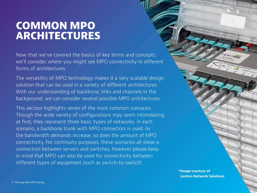
COMMON MPO ARCHITECTURES
Now that we’ve covered the basics of key terms and concepts, we’ll consider where you might see MPO connectivity in different forms of architectures.
The versatility of MPO technology makes it a very scalable design solution that can be used in a variety of different architectures. With our understanding of backbone, links and channels in the background, we can consider several possible MPO architectures.
This section highlights seven of the most common scenarios. Though the wide variety of configurations may seem intimidating at first, they represent three basic types of networks. In each scenario, a backbone trunk with MPO connectors is used. As the bandwidth demands increase, so does the amount of MPO connectivity. For continuity purposes, these scenarios all show a connection between servers and switches, however please keep in mind that MPO can also be used for connectivity between different types of equipment (such as switch-to-switch).
*Image courtesy of Leviton Network Solutions

switch SFP serverSFP
MPO BackboneLikely multiples of 12
i.e. 72, 96, 144, etc.
LC Links6 duplex LC links per cassette
LC Channels Connecting to 1/10/100G SFPs
10 Winning with MPO Testing
1G/10G MM Channels and 1/10/100G SM Channels
Scenario #1: LC-LC Links (LC-LC Channels)
In the figure below, notice the MPO backbone connected through to cassettes, and the cassettes break down into individual LC links and LC channels when equipment cords are added. When the requirement is to run up to 25G multimode and up to 200G singlemode, using an MPO backbone is much more efficient than than running numerous individual LC duplex pairs. In this example the designer chose to run a 72 fiber trunk, and break it into 36 duplex LC links using cassettes.. In this scenario, you don’t need to test the backbone fiber, but you will test the link at the front of the LC cassettes.

MPO BackboneLikely multiples of 12
i.e. 72, 96, 144, etc.
LC to MPO Links
LC Channels Connecting to 1/10/100G SFPs
switch serverSFPSFP
11 Winning with MPO Testing
Scenario #2: LC-MPO Links (LC-LC Channels)
Note that the architecture example below is nearly the same as the first example.The difference is that the link on the server side (as shown in the diagram) remains as MPO connectivity and then breaks out to LC after the link with an MPO-LC breakout cable. This is a good design choice when equipment rack-space is at a premium. In this sort of design scenario, also consider the trade off of flexibility. At the server end, there is opportunity for more density, and a cleaner solution. However, on the LC cassette side (the left side of the diagram), there’s still a fiber density challenge. In this scenario, one end of your link test will be LC while the other end will be MPO.

MPO BackboneLikely multiples of 12
i.e. 72, 96, 144, etc.
MPO Links
LC Channels Connecting to 1/10/100G SFPs
switch SFP SFP server
12 Winning with MPO Testing
Scenario #3: MPO-MPO Links (LC-LC Channels)
In the figure below, notice that the LC channels are the same as the other configurations. But rather than feeding your equipment with LC connectivity, there is MPO connectivity on both ends of the link. This provides for much more density at the patch panel on each end of the channel. The fiber management is neat and clean at the racks. However, as stated above, this may hinder flexibility. If there is a need to make changes at the switch end, an entire fan-out cable may need to be replaced. In this scenario, both ends of your link test will be MPO.
100GBASE-SR4 Optical Lane Assignments
IEEE Std 802.3bm-2015Amendment 3 to IEEE Std 802.3-2012
Tx Tx Tx Tx Rx Rx Rx Rx
switch
QSFP serverSFP
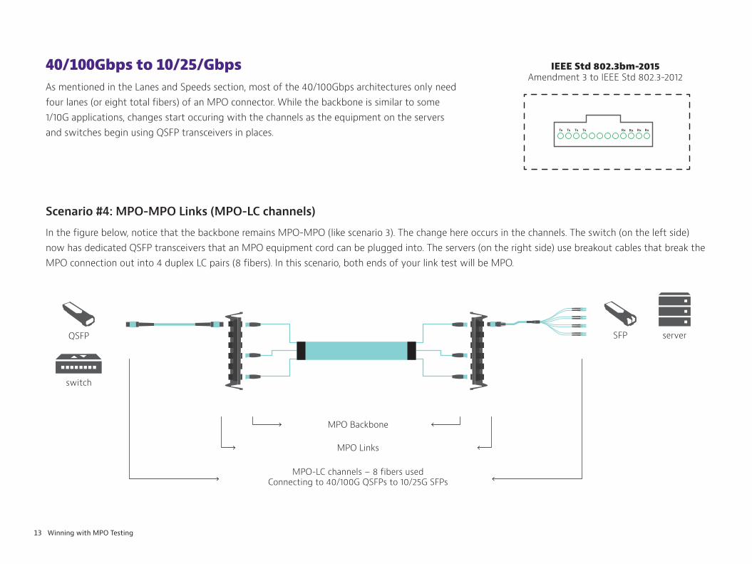
MPO-LC channels – 8 fibers usedConnecting to 40/100G QSFPs to 10/25G SFPs
MPO Links
MPO Backbone
13 Winning with MPO Testing
40/100Gbps to 10/25/GbpsAs mentioned in the Lanes and Speeds section, most of the 40/100Gbps architectures only need four lanes (or eight total fibers) of an MPO connector. While the backbone is similar to some 1/10G applications, changes start occuring with the channels as the equipment on the servers and switches begin using QSFP transceivers in places.
Scenario #4: MPO-MPO Links (MPO-LC channels)
In the figure below, notice that the backbone remains MPO-MPO (like scenario 3). The change here occurs in the channels. The switch (on the left side) now has dedicated QSFP transceivers that an MPO equipment cord can be plugged into. The servers (on the right side) use breakout cables that break the MPO connection out into 4 duplex LC pairs (8 fibers). In this scenario, both ends of your link test will be MPO.
serverSFP
switch
QSFP
MPO Backbone 12f/24f to each cassette
MPO to LC Links
MPO-LC channels – 8 fibers usedConnecting to 40/100G QSFPs to 10/25G SFPs
14 Winning with MPO Testing
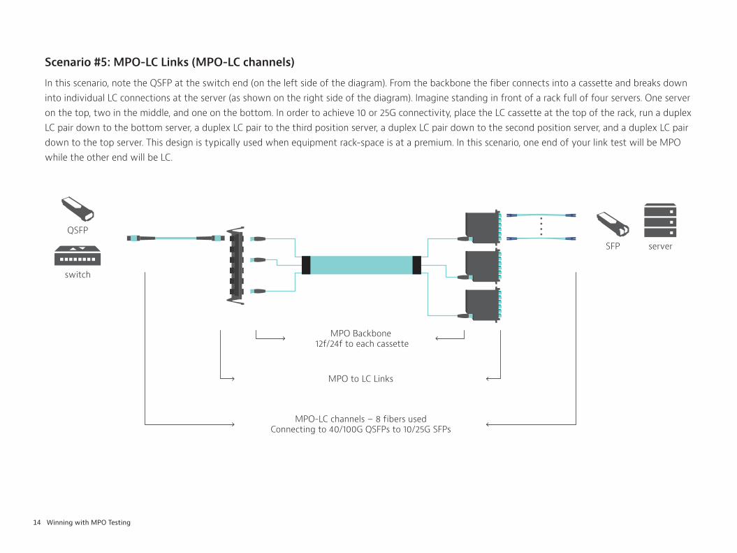
Scenario #5: MPO-LC Links (MPO-LC channels)
In this scenario, note the QSFP at the switch end (on the left side of the diagram). From the backbone the fiber connects into a cassette and breaks down into individual LC connections at the server (as shown on the right side of the diagram). Imagine standing in front of a rack full of four servers. One server on the top, two in the middle, and one on the bottom. In order to achieve 10 or 25G connectivity, place the LC cassette at the top of the rack, run a duplex LC pair down to the bottom server, a duplex LC pair to the third position server, a duplex LC pair down to the second position server, and a duplex LC pair down to the top server. This design is typically used when equipment rack-space is at a premium. In this scenario, one end of your link test will be MPO while the other end will be LC.
server
QSFP
switch
QSFP
MPO BackboneLikely multiples of 12 i.e. 72, 96, 144, etc.
12f MPO Links
12f MPO channelsConnecting to 40/100G QSFPs
15 Winning with MPO Testing
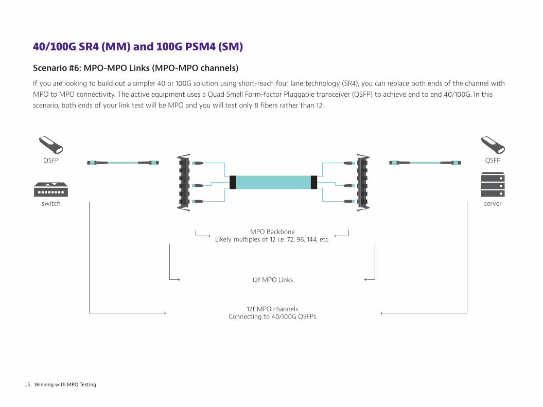
40/100G SR4 (MM) and 100G PSM4 (SM)
Scenario #6: MPO-MPO Links (MPO-MPO channels)
If you are looking to build out a simpler 40 or 100G solution using short-reach four lane technology (SR4), you can replace both ends of the channel with MPO to MPO connectivity. The active equipment uses a Quad Small Form-factor Pluggable transceiver (QSFP) to achieve end to end 40/100G. In this scenario, both ends of your link test will be MPO and you will test only 8 fibers rather than 12.

server
QSFPQSFP
switch
MPO Backbone24f to each cassette
12f MPO Linksonly 8 fibers populated
MPO channels – 8 fibers populatedConnecting to 40/100G QSFPs
16 Winning with MPO Testing
Scenario #7: MPO-MPO Links (MPO-MPO channels)
This scenario provides a true high-density 40/100G solution using a combination of different MPO connections. The backbone cable will deliver a series of 24 fiber MPO connectors that each plug into a cassette. Each cassette will break down into three separate, eight fiber connectivity to the QSFP. From a layout perspective this example is no different than scenario example 3, but there are considerations from a testing perspective. In this scenario, both ends of your link test will be MPO and you will test only 8 fibers rather than 12.

17 Winning with MPO Testing
TESTING MPO
If the various architectures we’ve outlined thus far seem familiar to you, this further underlines the reality that MPO isn’t the exception in fiber networks. It’s commonplace. As networks change, testing needs change as well.
18 Winning with MPO Testing
Why MPO testing is importantAt the end of the day, network owners and operators should expect their network to be reliable and dependable. For contractors that are hired for install and/or maintenance, they need to make sure their work meets the customer’s requirements. Providing accurate test results that are based on known standards is the guarantee that contractors and network owners can agree upon. After all, contractors need to keep their customers happy, and data center owners need confidence in their networks.
If you are a contractor, a large portion of your business is installing fiber infrastructure, testing and certification of installed fiber confirms that the system you installed supports the applications that will ultimately be carried on the fiber. The certification provides proof that your work was installed according to your customer’s requirements. These requirements are typically based on industry standards. In North America and other parts of the world, the most recognized standard for Optical Fiber Cabling and Components is TIA-568.3. For Europe and other parts of the world, the most recognized standard is IEC 14763-3. While these are different standards, the requirements in each of them are in strong harmonization. Both standards specify two tiers of certification testing for the installed links:
y Tier 1 (or basic): Provide Loss, Length, and Polarity information for each link
y Tier 2 (or extended) : Optical Time Domain Reflectormeter (OTDR) test information for each link
y Fiber end-face inspection and certification is also a requirement to ensure pristine end-face condition prior to mating
If you’re a network owner or operator, ensuring the integrity of your fiber infrastructure is essential to your business. Whether you manage a large enterprise, run multiple data centers, or a service provider using MPO in your FTTH or FTTA networks, understanding how your fiber network should be tested empowers you to have educated conversations and set clear expectations for your team and the contractors you hire about using the right MPO test tools and procedures to deliver measurable evidence of the network’s capabilities efficiently and within your budget.
LEARN MORE:
Contractors - read this article: Four Factors in Accurate Fiber Certification
End users - read this article: New Car Smell and the Art of Fiber Network Maintenance
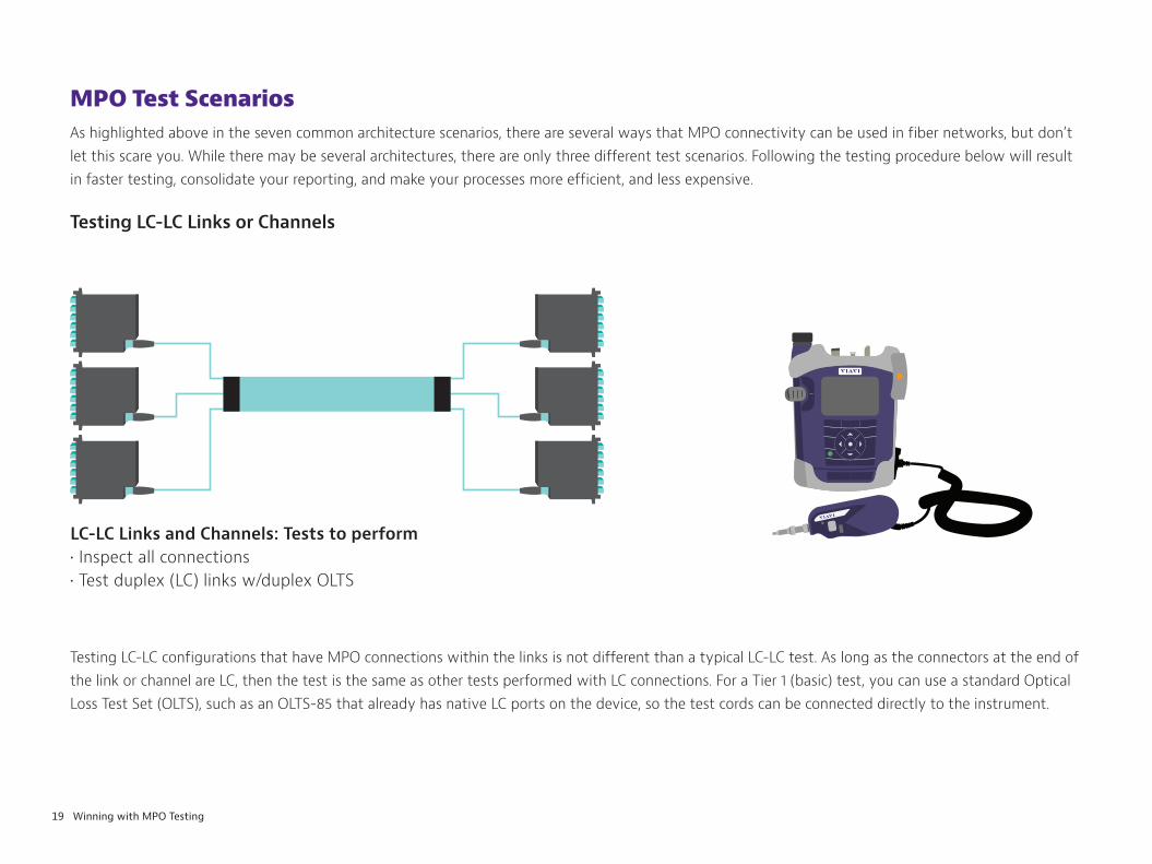
LC-LC Links and Channels: Tests to perform• Inspect all connections• Test duplex (LC) links w/duplex OLTS
19 Winning with MPO Testing
MPO Test ScenariosAs highlighted above in the seven common architecture scenarios, there are several ways that MPO connectivity can be used in fiber networks, but don’t let this scare you. While there may be several architectures, there are only three different test scenarios. Following the testing procedure below will result in faster testing, consolidate your reporting, and make your processes more efficient, and less expensive.
Testing LC-LC Links or Channels
Testing LC-LC configurations that have MPO connections within the links is not different than a typical LC-LC test. As long as the connectors at the end of the link or channel are LC, then the test is the same as other tests performed with LC connections. For a Tier 1 (basic) test, you can use a standard Optical Loss Test Set (OLTS), such as an OLTS-85 that already has native LC ports on the device, so the test cords can be connected directly to the instrument.
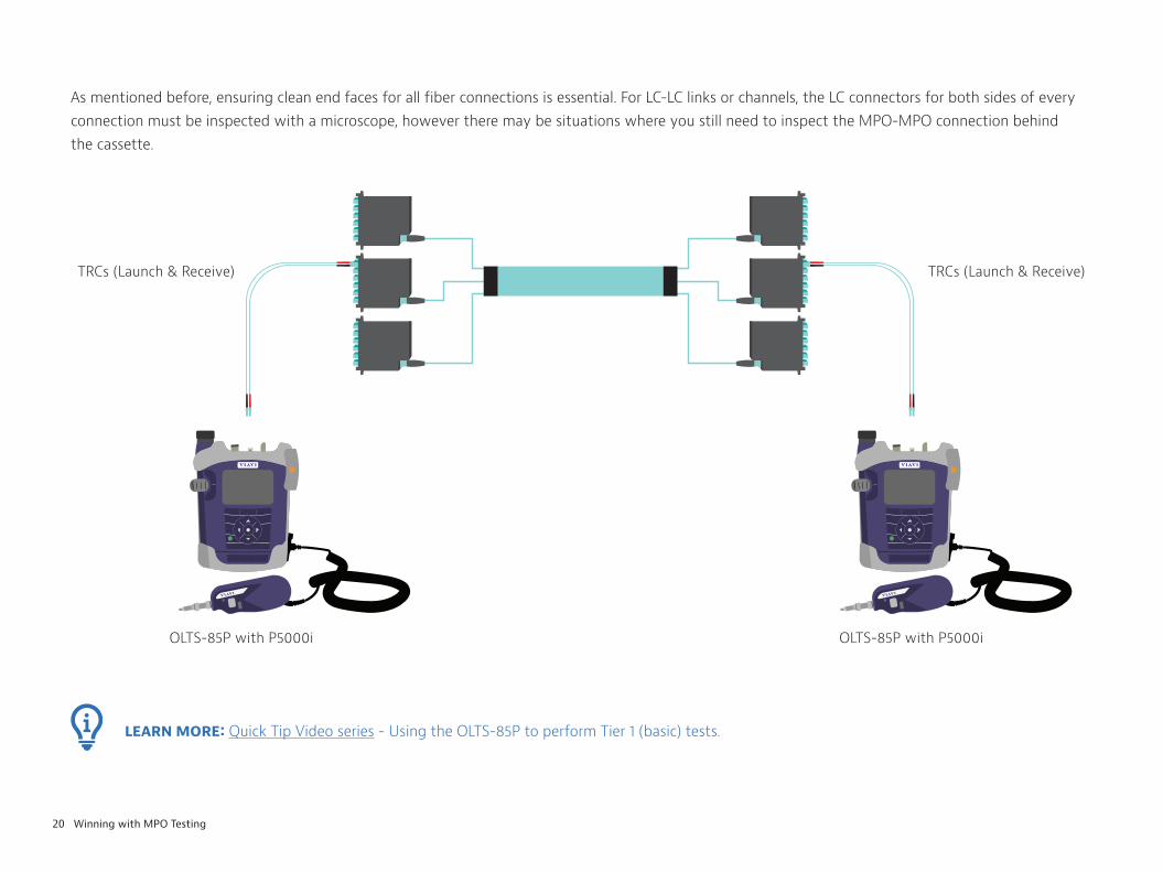
OLTS-85P with P5000i
TRCs (Launch & Receive) TRCs (Launch & Receive)
OLTS-85P with P5000i
LEARN MORE: Quick Tip Video series - Using the OLTS-85P to perform Tier 1 (basic) tests.
20 Winning with MPO Testing
As mentioned before, ensuring clean end faces for all fiber connections is essential. For LC-LC links or channels, the LC connectors for both sides of every connection must be inspected with a microscope, however there may be situations where you still need to inspect the MPO-MPO connection behind the cassette.
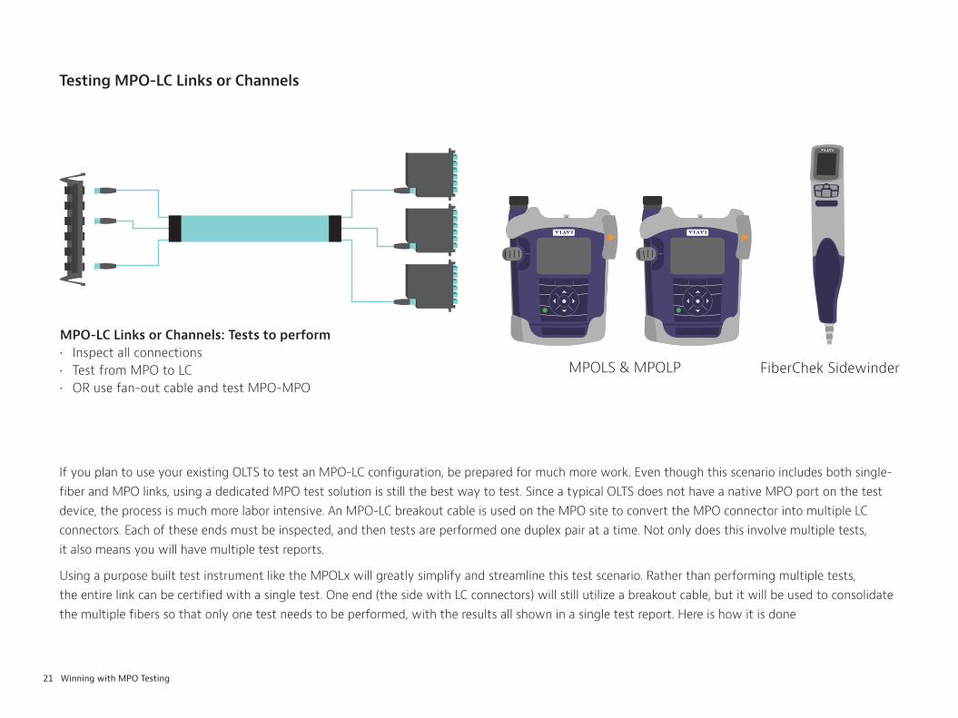
MPO-LC Links or Channels: Tests to perform• Inspect all connections• Test from MPO to LC • OR use fan-out cable and test MPO-MPO
MPOLS & MPOLP FiberChek Sidewinder
21 Winning with MPO Testing
Testing MPO-LC Links or Channels
If you plan to use your existing OLTS to test an MPO-LC configuration, be prepared for much more work. Even though this scenario includes both single-fiber and MPO links, using a dedicated MPO test solution is still the best way to test. Since a typical OLTS does not have a native MPO port on the test device, the process is much more labor intensive. An MPO-LC breakout cable is used on the MPO site to convert the MPO connector into multiple LC connectors. Each of these ends must be inspected, and then tests are performed one duplex pair at a time. Not only does this involve multiple tests, it also means you will have multiple test reports.
Using a purpose built test instrument like the MPOLx will greatly simplify and streamline this test scenario. Rather than performing multiple tests, the entire link can be certified with a single test. One end (the side with LC connectors) will still utilize a breakout cable, but it will be used to consolidate the multiple fibers so that only one test needs to be performed, with the results all shown in a single test report. Here is how it is done
Launch TRC Fan-out TRC
MPOLS MPOLP
Launch TRC Fan-out TRC
MPOLS MPOLP
Launch TRC
MPOLS MPOLP
22 Winning with MPO Testing
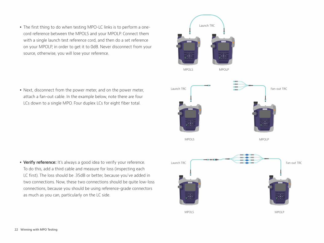
y Next, disconnect from the power meter, and on the power meter, attach a fan-out cable. In the example below, note there are four LCs down to a single MPO. Four duplex LCs for eight fiber total.
y Verify reference: It’s always a good idea to verify your reference. To do this, add a third cable and measure for loss (inspecting each LC first). The loss should be .35dB or better, because you’ve added in two connections. Now, these two connections should be quite low-loss connections, because you should be using reference-grade connectors as much as you can, particularly on the LC side.
y The first thing to do when testing MPO-LC links is to perform a one-cord reference between the MPOLS and your MPOLP. Connect them with a single launch test reference cord, and then do a set reference on your MPOLP, in order to get it to 0dB. Never disconnect from your source, otherwise, you will lose your reference.

Launch TRCFan-out TRC
MPOLS MPOLP
23 Winning with MPO Testing
y Once you verify that, then you remove your third TRC, and you connect up to your system under test. Now you measure loss of the link.
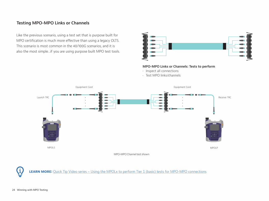
MPO-MPO Links or Channels: Tests to perform• Inspect all connections• Test MPO links/channels
Launch TRC
Equipment Cord Equipment Cord
Receive TRC
MPOLS MPOLP
LEARN MORE: Quick Tip Video series - Using the MPOLx to perform Tier 1 (basic) tests for MPO-MPO connections
MPO-MPO Channel test shown
24 Winning with MPO Testing
Testing MPO-MPO Links or Channels
Like the previous scenario, using a test set that is purpose built for MPO certification is much more effective than using a legacy OLTS. This scenario is most common in the 40/100G scenarios, and it is also the most simple...if you are using purpose built MPO test tools.
25 Winning with MPO Testing
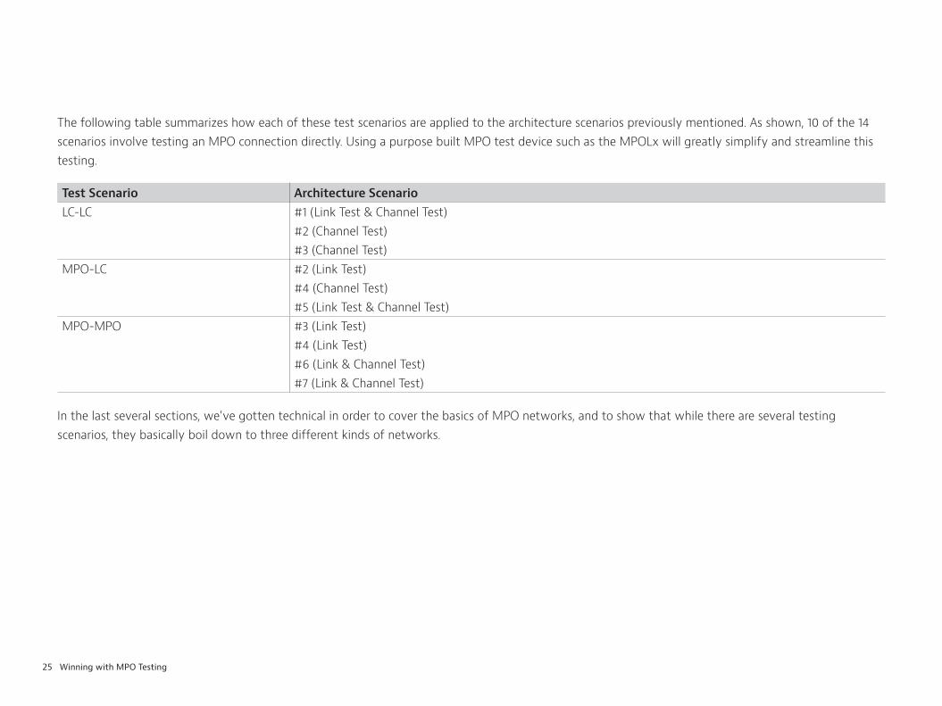
The following table summarizes how each of these test scenarios are applied to the architecture scenarios previously mentioned. As shown, 10 of the 14 scenarios involve testing an MPO connection directly. Using a purpose built MPO test device such as the MPOLx will greatly simplify and streamline this testing.
Test Scenario Architecture ScenarioLC-LC #1 (Link Test & Channel Test)
#2 (Channel Test) #3 (Channel Test)
MPO-LC #2 (Link Test) #4 (Channel Test) #5 (Link Test & Channel Test)
MPO-MPO #3 (Link Test) #4 (Link Test) #6 (Link & Channel Test) #7 (Link & Channel Test)
In the last several sections, we’ve gotten technical in order to cover the basics of MPO networks, and to show that while there are several testing scenarios, they basically boil down to three different kinds of networks.

MPO LinkUnder Test
Breakout Cable Breakout Cable
Two TestReference Cords
Two TestReference Cords
OLTSwith Duplex Ports
OLTSwith Duplex Ports
LEARN MORE: Use Case: Testing MPO Networks
26 Winning with MPO Testing
Challenges with Legacy Test Procedures
The Challenges of MPO Using Single/Duplex Fiber Testing Tools
When a technician uses a traditional single-fiber test instrument in an MPO application, there are some built-in challenges and complexities. Remember our analogy from before? When you test an MPO network with a legacy tool, it’s like using a pickaxe and shovel for a much bigger job. You can certainly get the job done, but you need to ensure the job is done quickly and efficiently. A legacy tool may not be your best solution. For one, fanout cables get messy during test procedures and deciphering which break-out strand corresponds to which fiber can be tricky. In addition, maintaining the performance quality of these reference cables over time requires proper care with end face inspection and cleaning. If one dust cap gets lost, the exposed end can get damaged, making the entire cable useless. It’s like hitting that water pipe and gaining a new problem you hadn’t bargained for.
In an environment where a legacy tool process is used, a typical OLTS has either LC or SC input ports. In this scenario, it’s not possible to plug an MPO connector into the test device. Instead an additional break-out/fan-out assembly is added between the MPO connector and the Test Reference Cables (TRCs) that connect to the test instrument port. These types of hybrid cables are necessary when testing with legacy tools, and the process becomes unnecessarily complicated (as seen in the figure below). Once again, this highlights the need for the right

MPO LinkUnder Test
Test Reference Cord
Test Reference Cord
MPOLS MPOLP
LEARN MORE: Use Case: Testing MPO Networks
FiberChek Sidewinder
27 Winning with MPO Testing
Benefits of New MPO Test Solutions
Technicians with history in the world of fiber are accustomed to working with single fiber connectors (whether they are SC or LC.) Making changes to their testing procedures may feel daunting, and adopting new tools and changing processes always comes with a learning curve. But these purpose-built MPO tools enable simpler testing processes. In the figure below, notice that each device features native MPO ports. This means fan-out cables are unnecessary. An MPO connectorized test reference cord connects directly to the device under test (DUT). Also note that devices such as the VIAVI MPOLx features a built-in microscope that allows the user to inspect the TRC cables and eliminate the need for additional tools with video display screens.

FiberChek Sidewinder
28 Winning with MPO Testing
End-Face InspectionUsing purpose-built tools for fiber inspection is also much faster and easier. In recent years, VIAVI Solutions has published many resources related to fiber inspection, and fiber end-face cleanliness as part of our “Inspect Before You Connect ” message. Although the standards bodies have established acceptance criteria for quality and cleanliness control of fiber end faces, it’s still an ongoing problem for technicians in the field. Debris on the end of a fiber connector can range from 2 - 15μm and is not visible to the naked eye. It’s imperative to inspect both sides of the fiber connection and ensure test ports and reference cords are clean as well to make sure there’s no debris cross contamination.
LEARN MORE:
Website - www.viavisolutions.com/inspect
White Paper - Testing Parallel Optics
Video - Dealing with Contamination on MPO Connectors
Brochure - Fiber Inspection Probe Microscopes

29 Winning with MPO Testing
WINNING WITH MPO TESTINGWhile there are certainly new complexities to consider, there’s no need to fear how MPO is changing fiber networks. Our hope is that we’ve simplified some MPO concepts that some may find intimidating. Throughout this article, we have referenced various resources that will equip you with the knowledge you need to install and service MPO networks effectively. All of these resources can also be found online at www.viavisolutions.com/mpo
If you’re an owner/operator of a network, you’re responsible for ensuring savings on testing processes. You’re counting on reliable test results, and you can’t afford to hire contractors that don’t use purpose built MPO tools. Consider the real world scenario from our introduction again: you can get the job done with a pickaxe and a shovel, but this route always ends up being more time consuming, complex, and expensive than you originally thought. Using legacy tools in an MPO environment requires too many workarounds you simply can’t afford. You need to have confidence in the accuracy of your test results, and you should feel empowered to expect the best from your contractors.
If you’re a contractor, having specialized fiber knowledge is no longer considered to be a mythical power like it was ten or fifteen years ago. It’s simply required knowledge. You need to be conversant with the changing needs of customers. You don’t want to get caught unprepared to test a robust MPO application with legacy tools. Now you have all the necessary information to succeed, remain competitive, and strengthen your business in the ever-changing world of fiber technology.

© 2019 VIAVI Solutions, Inc. Product specifications and descriptions in this document are subject to change without notice. winningmpo-wp-fit-nse-ae30187687 901 0319
Contact Us +1 844 GO VIAVI (+1 844 468 4284)
To reach the VIAVI office nearest you, visit viavisolutions.com/contact
viavisolutions.com