WINMAX GUIDE FOR ULTIMAX USERS - Stone Machinery, CNC ... · WinMax Guide for Ultimax Users...
90
April 2007 704-0001-828-DRAFT 7 Revision A WINMAX GUIDE FOR ULTIMAX USERS
-
Upload
hoangkhanh -
Category
Documents
-
view
243 -
download
5
Transcript of WINMAX GUIDE FOR ULTIMAX USERS - Stone Machinery, CNC ... · WinMax Guide for Ultimax Users...

April 2007 704-0001-828-DRAFT 7 Revision A
WINMAX GUIDEFOR ULTIMAX USERS
ii - WinMax Guide for Ultimax Users 704-0001-828-DRAFT 7 WinMax Guide for Ultimax Users
The information in this document is subject to change without notice and does not represent a commitment on the part of Hurco Companies, Inc. (Hurco). The software described in this document is furnished under the License Agreement to customers. It is against the law to copy the software on any medium except as specifically allowed in the license agreement. The purchaser may make copies of the software for backup purposes. No part of this document may be reproduced or transmitted in any form or by any means, electronic or mechanical, including photocopying, for any purpose without the express written permission of the Hurco machine tool owner.
Hurco Manufacturing Company reserves the right to incorporate any modification or improvements in machines and machine specifications which it considers necessary, and does not assume any obligation to make any said changes in machines or equipment previously sold.
Hurco products and services are subject to Hurco’s then current prices, terms, and conditions, which are subject to change without notice.
© 2007 Hurco Companies, Inc. All rights reserved.
Patents: U.S. Patents B14,477,754; 5,453,933; Canadian Patent 1,102,434; Japanese Patents 1,649,006 and 1,375,124; other Patents pending.
Hurco, Max, Ultimax, and WinMax are Registered Trademarks of Hurco Companies, Inc.
AutoCAD, Autodesk, and DXF are registered trademarks of Autodesk, Inc.
MS-DOS, Microsoft, and Windows are registered trademarks of Microsoft Corporation.
Many of the designations used by manufacturers and sellers to distinguish their products are claimed as trademarks. Hurco has listed here all trademarks of which it is aware. For more information about Hurco products and services, contact:
Hurco Companies, Inc. One Technology WayP.O. Box 68180Indianapolis, IN 46268-0180Tel (317) 293-5309 (products)
(317) 298-2635 (service)Fax (317) 328-2812 (service)
For Hurco subsidiary contact information, go to Hurco’s Web site:www.hurco.com

WinMax Guide for Ultimax Users 704-0001-828-DRAFT 7 Table of Contents — iii
TABLE OF CONTENTS
WinMax Guide for Ultimax Users
About this Guide . . . . . . . . . . . . . . . . . . . . . . . . . . . . . . . . . . . . . . . . . . . . 1
WinMax System Basics . . . . . . . . . . . . . . . . . . . . . . . . . . . . . . . . . . . . . . . . 2WinMax Interface Environment . . . . . . . . . . . . . . . . . . . . . . . . . . . . . . . . 2
Softkeys . . . . . . . . . . . . . . . . . . . . . . . . . . . . . . . . . . . . . . . . . . . . . 2Drop-down Lists . . . . . . . . . . . . . . . . . . . . . . . . . . . . . . . . . . . . . . . 2Expand and Collapse Files . . . . . . . . . . . . . . . . . . . . . . . . . . . . . . . . . 3Pop-ups . . . . . . . . . . . . . . . . . . . . . . . . . . . . . . . . . . . . . . . . . . . . . 3Status Bar . . . . . . . . . . . . . . . . . . . . . . . . . . . . . . . . . . . . . . . . . . . 4
Calculator . . . . . . . . . . . . . . . . . . . . . . . . . . . . . . . . . . . . . . . . . 5Online Help . . . . . . . . . . . . . . . . . . . . . . . . . . . . . . . . . . . . . . . . . . . . . 5
Input Mode . . . . . . . . . . . . . . . . . . . . . . . . . . . . . . . . . . . . . . . . . . . . . . . . 7Part Setup . . . . . . . . . . . . . . . . . . . . . . . . . . . . . . . . . . . . . . . . . . . . . . 8
Stock Geometry . . . . . . . . . . . . . . . . . . . . . . . . . . . . . . . . . . . . . . . . 8Part Programming . . . . . . . . . . . . . . . . . . . . . . . . . . . . . . . . . . . . . . . . . 10
Taps . . . . . . . . . . . . . . . . . . . . . . . . . . . . . . . . . . . . . . . . . . . . . 12Tool Selection . . . . . . . . . . . . . . . . . . . . . . . . . . . . . . . . . . . . . . . . . 13
Tool Number . . . . . . . . . . . . . . . . . . . . . . . . . . . . . . . . . . . . . . . 13Select Tool from List . . . . . . . . . . . . . . . . . . . . . . . . . . . . . . . . . . 14
Position Block . . . . . . . . . . . . . . . . . . . . . . . . . . . . . . . . . . . . . . . . . 15Milling Blocks . . . . . . . . . . . . . . . . . . . . . . . . . . . . . . . . . . . . . . . . . 16
Mill Contours . . . . . . . . . . . . . . . . . . . . . . . . . . . . . . . . . . . . . . . 17Lettering . . . . . . . . . . . . . . . . . . . . . . . . . . . . . . . . . . . . . . . . . . 17
Pattern Block . . . . . . . . . . . . . . . . . . . . . . . . . . . . . . . . . . . . . . . . . . 19Miscellaneous Block . . . . . . . . . . . . . . . . . . . . . . . . . . . . . . . . . . . . . 19
Comment Block . . . . . . . . . . . . . . . . . . . . . . . . . . . . . . . . . . . . . 19NC/Conversational Merge . . . . . . . . . . . . . . . . . . . . . . . . . . . . . . . . . 20Swept Surface . . . . . . . . . . . . . . . . . . . . . . . . . . . . . . . . . . . . . . . . . 22
Program Parameters . . . . . . . . . . . . . . . . . . . . . . . . . . . . . . . . . . . . . . . 23SelectSurface Finish Quality . . . . . . . . . . . . . . . . . . . . . . . . . . . . . . . . . . 24
SFQ in Conversational Programming . . . . . . . . . . . . . . . . . . . . . . . . . 24Changing SFQ in Program Parameters . . . . . . . . . . . . . . . . . . . . . . 24Changing SFQ in Individual Data Blocks . . . . . . . . . . . . . . . . . . . . 25Changing SFQ with Change Parameters Block . . . . . . . . . . . . . . . . 25
SFQ in NC Programming . . . . . . . . . . . . . . . . . . . . . . . . . . . . . . . . . . 26Global Program Parameters . . . . . . . . . . . . . . . . . . . . . . . . . . . . . 26G5.3P NC Command . . . . . . . . . . . . . . . . . . . . . . . . . . . . . . . . . . 26Individual Tool . . . . . . . . . . . . . . . . . . . . . . . . . . . . . . . . . . . . . . 26
Import Functions . . . . . . . . . . . . . . . . . . . . . . . . . . . . . . . . . . . . . . . . . 27Erase Functions . . . . . . . . . . . . . . . . . . . . . . . . . . . . . . . . . . . . . . . . . . 28Program Manager . . . . . . . . . . . . . . . . . . . . . . . . . . . . . . . . . . . . . . . . . 29
Program Properties . . . . . . . . . . . . . . . . . . . . . . . . . . . . . . . . . . . . . 32Disk Operations . . . . . . . . . . . . . . . . . . . . . . . . . . . . . . . . . . . . . . . . 33
Tool and Material Library . . . . . . . . . . . . . . . . . . . . . . . . . . . . . . . . . . . . . . 35Tool Management . . . . . . . . . . . . . . . . . . . . . . . . . . . . . . . . . . . . . . . . . 35
Spindle . . . . . . . . . . . . . . . . . . . . . . . . . . . . . . . . . . . . . . . . . . . . . . 35
iv - Table of Contents 704-0001-828-DRAFT 7 WinMax Guide for Ultimax Users
Auto . . . . . . . . . . . . . . . . . . . . . . . . . . . . . . . . . . . . . . . . . . . . . . . . 36Manual . . . . . . . . . . . . . . . . . . . . . . . . . . . . . . . . . . . . . . . . . . . . . . . 37
Advanced Tool Settings . . . . . . . . . . . . . . . . . . . . . . . . . . . . . . . . . . . . . . 38Geometry . . . . . . . . . . . . . . . . . . . . . . . . . . . . . . . . . . . . . . . . . . . . . 38Feed and Speed . . . . . . . . . . . . . . . . . . . . . . . . . . . . . . . . . . . . . . . . 40NC SFQ . . . . . . . . . . . . . . . . . . . . . . . . . . . . . . . . . . . . . . . . . . . . . . 41Supplier . . . . . . . . . . . . . . . . . . . . . . . . . . . . . . . . . . . . . . . . . . . . . . 42Notes . . . . . . . . . . . . . . . . . . . . . . . . . . . . . . . . . . . . . . . . . . . . . . . . 43
Tool and Material Database . . . . . . . . . . . . . . . . . . . . . . . . . . . . . . . . . . . 44
Review Mode . . . . . . . . . . . . . . . . . . . . . . . . . . . . . . . . . . . . . . . . . . . . . . . . 46Part Program Tool Review . . . . . . . . . . . . . . . . . . . . . . . . . . . . . . . . . . . . 48
Tool Matching . . . . . . . . . . . . . . . . . . . . . . . . . . . . . . . . . . . . . . . . . . 49Tool Matching Results . . . . . . . . . . . . . . . . . . . . . . . . . . . . . . . . . . 49
Auxiliary Mode . . . . . . . . . . . . . . . . . . . . . . . . . . . . . . . . . . . . . . . . . . . . . . 51Utilities . . . . . . . . . . . . . . . . . . . . . . . . . . . . . . . . . . . . . . . . . . . . . . . . . 52
UltiNet . . . . . . . . . . . . . . . . . . . . . . . . . . . . . . . . . . . . . . . . . . . . . . . 60UltiNet FTP Client . . . . . . . . . . . . . . . . . . . . . . . . . . . . . . . . . . . . . 60UltiNet FTP Server . . . . . . . . . . . . . . . . . . . . . . . . . . . . . . . . . . . . 61
Tool Utilities and Settings . . . . . . . . . . . . . . . . . . . . . . . . . . . . . . . . . . 63Tool Information and Printing . . . . . . . . . . . . . . . . . . . . . . . . . . . . 65Import and Export . . . . . . . . . . . . . . . . . . . . . . . . . . . . . . . . . . . . 67
Auto Mode . . . . . . . . . . . . . . . . . . . . . . . . . . . . . . . . . . . . . . . . . . . . . . . . . 68
Manual Mode . . . . . . . . . . . . . . . . . . . . . . . . . . . . . . . . . . . . . . . . . . . . . . . . 70
Graphics . . . . . . . . . . . . . . . . . . . . . . . . . . . . . . . . . . . . . . . . . . . . . . . . . . . 71Toolpath Graphics . . . . . . . . . . . . . . . . . . . . . . . . . . . . . . . . . . . . . . . . . . 73Solid Graphics . . . . . . . . . . . . . . . . . . . . . . . . . . . . . . . . . . . . . . . . . . . . 73DXF Option . . . . . . . . . . . . . . . . . . . . . . . . . . . . . . . . . . . . . . . . . . . . . . 75
Appendix A—Toolbar Icons . . . . . . . . . . . . . . . . . . . . . . . . . . . . . . . . . . . . . . 76
Appendix B—Keyboard Shortcuts . . . . . . . . . . . . . . . . . . . . . . . . . . . . . . . . . . 78
Index . . . . . . . . . . . . . . . . . . . . . . . . . . . . . . . . . . . . . . . . . . . . . . . . . . . . . 1
WinMax Guide for Ultimax Users 704-0001-828-DRAFT 7 List of Figures — 3
LIST OF FIGURES
Figure 1. Example of a drop-down list . . . . . . . . . . . . . . . . . . . . . . . . . . . . . . . . 2Figure 2. Example of Expand and Collapse Files . . . . . . . . . . . . . . . . . . . . . . . . . . 3Figure 3. Pop-up message example . . . . . . . . . . . . . . . . . . . . . . . . . . . . . . . . . . 3Figure 4. Pop-up showing minimize and close icons . . . . . . . . . . . . . . . . . . . . . . . 3Figure 5. Status Bar and other areas . . . . . . . . . . . . . . . . . . . . . . . . . . . . . . . . . 4Figure 6. Calculator pop-up . . . . . . . . . . . . . . . . . . . . . . . . . . . . . . . . . . . . . . . . 5Figure 7. Help screen example . . . . . . . . . . . . . . . . . . . . . . . . . . . . . . . . . . . . . 6Figure 8. Input screen . . . . . . . . . . . . . . . . . . . . . . . . . . . . . . . . . . . . . . . . . . . 7Figure 9. Part Setup screen and new Stock Geometry softkey . . . . . . . . . . . . . . . . 8Figure 10. Stock Geometry screen . . . . . . . . . . . . . . . . . . . . . . . . . . . . . . . . . . . 8Figure 11. Tool Setup screen . . . . . . . . . . . . . . . . . . . . . . . . . . . . . . . . . . . . . . . 10Figure 12. Tap Tool Type in Tool Setup . . . . . . . . . . . . . . . . . . . . . . . . . . . . . . . . 12Figure 13. Tap Thread Diameter selection . . . . . . . . . . . . . . . . . . . . . . . . . . . . . . 12Figure 14. Tool Number field in Tool Setup . . . . . . . . . . . . . . . . . . . . . . . . . . . . . 13Figure 15. Select Tool from List softkey . . . . . . . . . . . . . . . . . . . . . . . . . . . . . . . 14Figure 16. Selecting Tool from Tool Library . . . . . . . . . . . . . . . . . . . . . . . . . . . . . 14Figure 17. Field is populated with selected tool . . . . . . . . . . . . . . . . . . . . . . . . . . 15Figure 18. Position Block . . . . . . . . . . . . . . . . . . . . . . . . . . . . . . . . . . . . . . . . . . 15Figure 19. Mill Frame Block . . . . . . . . . . . . . . . . . . . . . . . . . . . . . . . . . . . . . . . . 16Figure 20. Mill Contour Block . . . . . . . . . . . . . . . . . . . . . . . . . . . . . . . . . . . . . . . 17Figure 21. True-Type Lettering Program Block . . . . . . . . . . . . . . . . . . . . . . . . . . . 17Figure 22. Select New Font . . . . . . . . . . . . . . . . . . . . . . . . . . . . . . . . . . . . . . . . 18Figure 23. Rectangular Pattern Block . . . . . . . . . . . . . . . . . . . . . . . . . . . . . . . . . 19Figure 24. Comment Block . . . . . . . . . . . . . . . . . . . . . . . . . . . . . . . . . . . . . . . . 19Figure 25. NC/Conversational Merge Block . . . . . . . . . . . . . . . . . . . . . . . . . . . . . 21Figure 26. Swept Surface Programming example . . . . . . . . . . . . . . . . . . . . . . . . . 22Figure 27. Program Parameters: Probing screen . . . . . . . . . . . . . . . . . . . . . . . . . 23Figure 28. Performance Tab in Program Parameters Screen . . . . . . . . . . . . . . . . . 24Figure 29. Selecting SFQ in Data Block . . . . . . . . . . . . . . . . . . . . . . . . . . . . . . . . 25Figure 30. NC SFQ settings in Advanced Tool Settings . . . . . . . . . . . . . . . . . . . . . 26Figure 31. Import Functions screen for Conversational . . . . . . . . . . . . . . . . . . . . . 27Figure 32. Erase functions softkeys . . . . . . . . . . . . . . . . . . . . . . . . . . . . . . . . . . 28Figure 33. WinMax Program Manager . . . . . . . . . . . . . . . . . . . . . . . . . . . . . . . . . 29Figure 34. Load Program screen to open a program . . . . . . . . . . . . . . . . . . . . . . . 30Figure 35. Program Properties screen . . . . . . . . . . . . . . . . . . . . . . . . . . . . . . . . . 32Figure 36. Disk Operations screen: directory highlighted view . . . . . . . . . . . . . . . . 33Figure 37. Disk Operations screen: files highlighted view . . . . . . . . . . . . . . . . . . . 34Figure 38. Tool Library: Spindle Screen . . . . . . . . . . . . . . . . . . . . . . . . . . . . . . . 35Figure 39. Tool Library: Auto Tools Screen . . . . . . . . . . . . . . . . . . . . . . . . . . . . . 36Figure 40. Tool Library Manual Tools Screen . . . . . . . . . . . . . . . . . . . . . . . . . . . . 37Figure 41. Advanced Tool Settings: Geometry . . . . . . . . . . . . . . . . . . . . . . . . . . . 38Figure 42. Advanced Tool Settings: Feed and Speed . . . . . . . . . . . . . . . . . . . . . . 40Figure 43. Advanced Tool Settings: NC SFQ . . . . . . . . . . . . . . . . . . . . . . . . . . . . 41Figure 44. Advanced Tool Settings: Supplier . . . . . . . . . . . . . . . . . . . . . . . . . . . . 42Figure 45. Advanced Tool Settings: Notes . . . . . . . . . . . . . . . . . . . . . . . . . . . . . . 43Figure 46. Tool and Material Database screen:Tools tab . . . . . . . . . . . . . . . . . . . . 44Figure 47. Tool and Material Database screen: Materials tab . . . . . . . . . . . . . . . . . 45Figure 48. Program Review Screen . . . . . . . . . . . . . . . . . . . . . . . . . . . . . . . . . . . 46Figure 49. Multiple Block Functions in Program Review . . . . . . . . . . . . . . . . . . . . . 47Figure 50. Part Program Tool Review . . . . . . . . . . . . . . . . . . . . . . . . . . . . . . . . . 48

4 - List of Tables 704-0001-828-DRAFT 7 WinMax Guide for Ultimax Users
Figure 51. Part Program Tool Review Matching Screen . . . . . . . . . . . . . . . . . . . . . 49Figure 52. Tool Matching Results . . . . . . . . . . . . . . . . . . . . . . . . . . . . . . . . . . . . 50Figure 53. Auxiliary Screen . . . . . . . . . . . . . . . . . . . . . . . . . . . . . . . . . . . . . . . . 51Figure 54. Utilities Screen . . . . . . . . . . . . . . . . . . . . . . . . . . . . . . . . . . . . . . . . . 52Figure 55. System Configuration . . . . . . . . . . . . . . . . . . . . . . . . . . . . . . . . . . . . 52Figure 56. User Preference Screen in Utilities . . . . . . . . . . . . . . . . . . . . . . . . . . . 53Figure 57. User Interface Settings in Utilities . . . . . . . . . . . . . . . . . . . . . . . . . . . 54Figure 58. Conversational Settings in Utilities . . . . . . . . . . . . . . . . . . . . . . . . . . . 55Figure 59. NC Settings in Utilities . . . . . . . . . . . . . . . . . . . . . . . . . . . . . . . . . . . 56Figure 60. Autosave Settings in Utilities . . . . . . . . . . . . . . . . . . . . . . . . . . . . . . . 57Figure 61. User Preferences Screen 2 in Utilities (accessed with MORE softkey) . . . 58Figure 62. Printing Setup in Utilities . . . . . . . . . . . . . . . . . . . . . . . . . . . . . . . . . . 59Figure 63. FTP Host List screen . . . . . . . . . . . . . . . . . . . . . . . . . . . . . . . . . . . . . 60Figure 64. FTP Manager Screen . . . . . . . . . . . . . . . . . . . . . . . . . . . . . . . . . . . . . 61Figure 65. FTP Sever Settings screen . . . . . . . . . . . . . . . . . . . . . . . . . . . . . . . . . 62Figure 66. Tool Utilities and Settings with Tool & Material Library option . . . . . . . . 63Figure 67. Tool Utilities and Settings without Tool & Material Library option . . . . . . 64Figure 68. Tool Information and Printing . . . . . . . . . . . . . . . . . . . . . . . . . . . . . . 65Figure 69. Import and Export Softkeys . . . . . . . . . . . . . . . . . . . . . . . . . . . . . . . . 67Figure 70. Auto Screen (NC) . . . . . . . . . . . . . . . . . . . . . . . . . . . . . . . . . . . . . . . 68Figure 71. NC Run Program screen . . . . . . . . . . . . . . . . . . . . . . . . . . . . . . . . . . 69Figure 72. NC Monitor screen . . . . . . . . . . . . . . . . . . . . . . . . . . . . . . . . . . . . . . 69Figure 73. Manual Screen . . . . . . . . . . . . . . . . . . . . . . . . . . . . . . . . . . . . . . . . . 70Figure 74. Graphics Settings . . . . . . . . . . . . . . . . . . . . . . . . . . . . . . . . . . . . . . . 71Figure 75. Toolpath graphic display . . . . . . . . . . . . . . . . . . . . . . . . . . . . . . . . . . 73Figure 76. Solid graphic display . . . . . . . . . . . . . . . . . . . . . . . . . . . . . . . . . . . . . 73Figure 77. Load DXF FIle screen . . . . . . . . . . . . . . . . . . . . . . . . . . . . . . . . . . . . 75Figure 78. DXF . . . . . . . . . . . . . . . . . . . . . . . . . . . . . . . . . . . . . . . . . . . . . . . . 75
LIST OF TABLES
Table 1. Recommended SFQ values . . . . . . . . . . . . . . . . . . . . . . . . . . . . . . . . . . 24Table 2. Geometry Fields . . . . . . . . . . . . . . . . . . . . . . . . . . . . . . . . . . . . . . . . . 39Table 3. WinMax Keyboard Shortcuts . . . . . . . . . . . . . . . . . . . . . . . . . . . . . . . . . 78
WinMax Guide for Ultimax Users 704-0001-828-DRAFT 7 About this Guide — 1
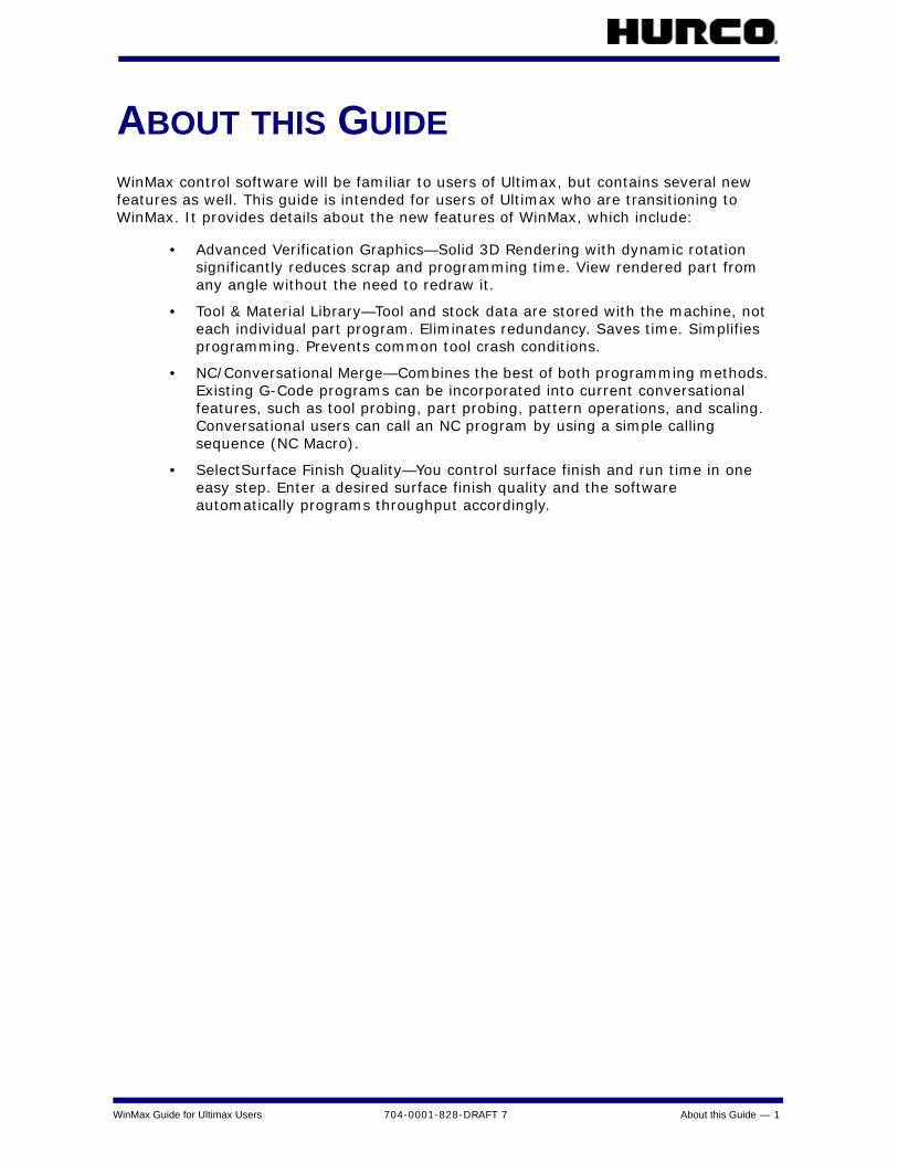
ABOUT THIS GUIDEWinMax control software will be familiar to users of Ultimax, but contains several new features as well. This guide is intended for users of Ultimax who are transitioning to WinMax. It provides details about the new features of WinMax, which include:
• Advanced Verification Graphics—Solid 3D Rendering with dynamic rotation significantly reduces scrap and programming time. View rendered part from any angle without the need to redraw it.
• Tool & Material Library—Tool and stock data are stored with the machine, not each individual part program. Eliminates redundancy. Saves time. Simplifies programming. Prevents common tool crash conditions.
• NC/Conversational Merge—Combines the best of both programming methods. Existing G-Code programs can be incorporated into current conversational features, such as tool probing, part probing, pattern operations, and scaling. Conversational users can call an NC program by using a simple calling sequence (NC Macro).
• SelectSurface Finish Quality—You control surface finish and run time in one easy step. Enter a desired surface finish quality and the software automatically programs throughput accordingly.
2 - WinMax System Basics 704-0001-828-DRAFT 7 WinMax Guide for Ultimax Users
WINMAX SYSTEM BASICSUsers familiar with Ultimax will recognize many of the screens in WinMax; many screens contain the same information as Ultimax but the fields occupy a different location on the screen.
WinMax Interface EnvironmentThere are three ways to navigate and enter data for programming:
• Ultimax classic edit mode—use the console keys; for example, the arrow keys for navigation and the enter key to accept data typed into a field
• Touchscreen—use the stylus or other pointing device to select softkeys and drop-down lists for data entry and programming
• Keyboard—use the function (F1-F12) keys and other keyboard shortcuts for navigation and to call up screens
SoftkeysSoftkeys appear as buttons on the screen; their default location is the right side of the screen, but they can also be positioned on the left by changing the setting in User Preferences (see the “Utilities” section for more information). Select a softkey using one of these methods:
• On the screen, touch the softkey
• On the console, simultaneously press the F key and the number that corresponds to the softkey (for example, F + 1 will select the F1 softkey). For dual-console machines, ALT + the softkey number will select softkeys on the graphics screen.
• On the keyboard (if using), press the corresponding function key (F1, F2, F3, etc).
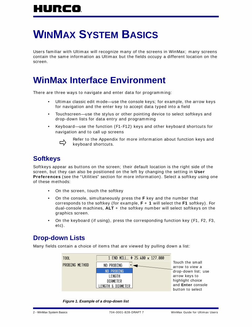
Drop-down ListsMany fields contain a choice of items that are viewed by pulling down a list:
Figure 1. Example of a drop-down list
Refer to the Appendix for more information about function keys and keyboard shortcuts.
Touch the smallarrow to view adrop-down list; usearrow keys tohighlight choiceand Enter consolebutton to select
WinMax Guide for Ultimax Users 704-0001-828-DRAFT 7 WinMax System Basics — 3
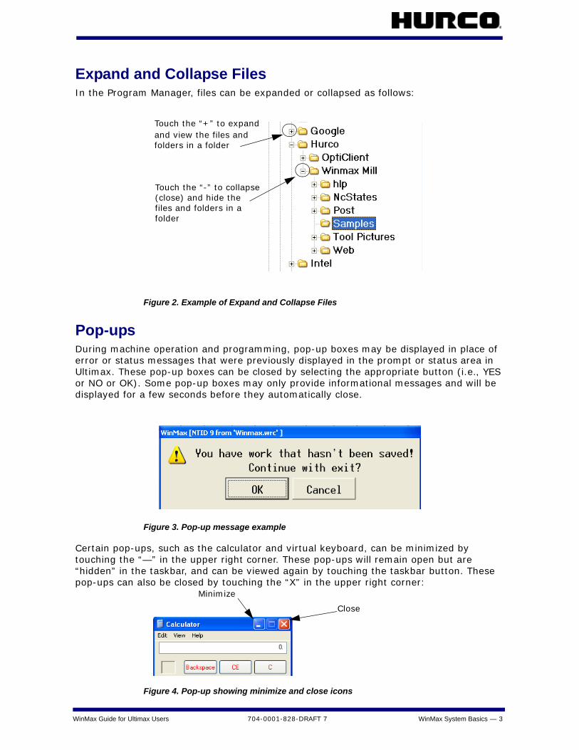
Expand and Collapse FilesIn the Program Manager, files can be expanded or collapsed as follows:
Figure 2. Example of Expand and Collapse Files
Pop-upsDuring machine operation and programming, pop-up boxes may be displayed in place of error or status messages that were previously displayed in the prompt or status area in Ultimax. These pop-up boxes can be closed by selecting the appropriate button (i.e., YES or NO or OK). Some pop-up boxes may only provide informational messages and will be displayed for a few seconds before they automatically close.
Figure 3. Pop-up message example
Certain pop-ups, such as the calculator and virtual keyboard, can be minimized by touching the “—” in the upper right corner. These pop-ups will remain open but are “hidden” in the taskbar, and can be viewed again by touching the taskbar button. These pop-ups can also be closed by touching the “X” in the upper right corner:
Figure 4. Pop-up showing minimize and close icons
Touch the “+” to expandand view the files and
Touch the “-” to collapse
folders in a folder
(close) and hide thefiles and folders in afolder
Minimize
Close
4 - WinMax System Basics 704-0001-828-DRAFT 7 WinMax Guide for Ultimax Users
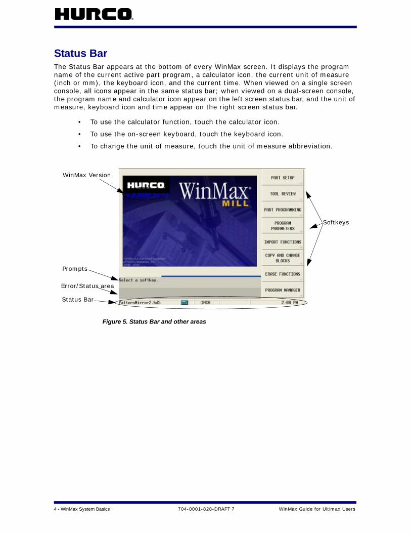
Status BarThe Status Bar appears at the bottom of every WinMax screen. It displays the program name of the current active part program, a calculator icon, the current unit of measure (inch or mm), the keyboard icon, and the current time. When viewed on a single screen console, all icons appear in the same status bar; when viewed on a dual-screen console, the program name and calculator icon appear on the left screen status bar, and the unit of measure, keyboard icon and time appear on the right screen status bar.
• To use the calculator function, touch the calculator icon.
• To use the on-screen keyboard, touch the keyboard icon.
• To change the unit of measure, touch the unit of measure abbreviation.
Figure 5. Status Bar and other areas
Softkeys
Status Bar
Error/Status area
Prompts
WinMax Version

WinMax Guide for Ultimax Users 704-0001-828-DRAFT 7 WinMax System Basics — 5
CalculatorClick the calculator icon in the Status Bar to open the calculator. The calculator appears on screen and is operated using the stylus to select the calculator keys on screen.
Figure 6. Calculator pop-up
When the calculator is minimized (with the “—” in the upper right corner), the last calculation is retained, but when it is closed (with the “X” in the upper right corner), the last calculation is erased.
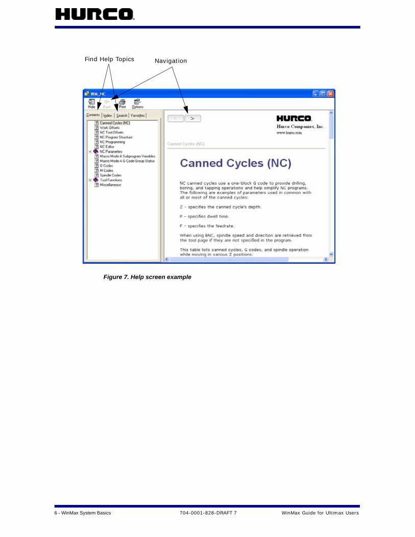
Online HelpOnline Help provides information about using WinMax. The Help is context-sensitive to the screen level. Press the console Help button to display the Help topic for the current screen. The following list describes Help functions:
• Buttons in the upper left-hand corner of Help screens are used to move through Help topics and print screens.
• Use the Hide button to hide the navigation pane.
• Use the Back button to return to the previous Help screen.
• Use the Print button to print the current Help screen, if there is a printer attached and configured.
• Select the Contents tab for a list of information sorted by subject. Touch the “+” to expand the topic and view sub-topics.
• Select the Index tab to search for keywords.
• Select the Search tab to search Help for a word or phrase.
• Select the Favorites tab to access, add, or remove a Help topic.
• Use the arrow buttons to move between pages within a Help topic.
6 - WinMax System Basics 704-0001-828-DRAFT 7 WinMax Guide for Ultimax Users
Figure 7. Help screen example
NavigationFind Help Topics
WinMax Guide for Ultimax Users 704-0001-828-DRAFT 7 Input Mode — 7
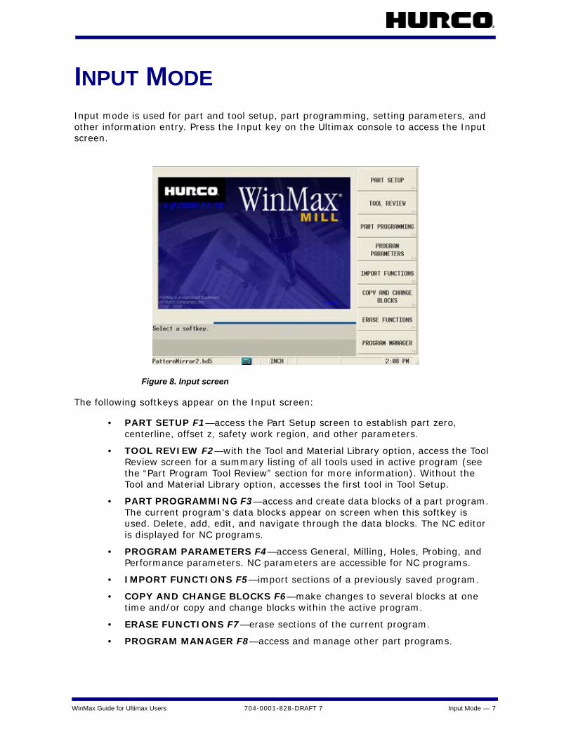
INPUT MODEInput mode is used for part and tool setup, part programming, setting parameters, and other information entry. Press the Input key on the Ultimax console to access the Input screen.
Figure 8. Input screen
The following softkeys appear on the Input screen:
• PART SETUP F1—access the Part Setup screen to establish part zero, centerline, offset z, safety work region, and other parameters.
• TOOL REVIEW F2—with the Tool and Material Library option, access the Tool Review screen for a summary listing of all tools used in active program (see the “Part Program Tool Review” section for more information). Without the Tool and Material Library option, accesses the first tool in Tool Setup.
• PART PROGRAMMING F3—access and create data blocks of a part program. The current program's data blocks appear on screen when this softkey is used. Delete, add, edit, and navigate through the data blocks. The NC editor is displayed for NC programs.
• PROGRAM PARAMETERS F4—access General, Milling, Holes, Probing, and Performance parameters. NC parameters are accessible for NC programs.
• IMPORT FUNCTIONS F5—import sections of a previously saved program.
• COPY AND CHANGE BLOCKS F6—make changes to several blocks at one time and/or copy and change blocks within the active program.
• ERASE FUNCTIONS F7—erase sections of the current program.
• PROGRAM MANAGER F8—access and manage other part programs.
8 - Input Mode 704-0001-828-DRAFT 7 WinMax Guide for Ultimax Users
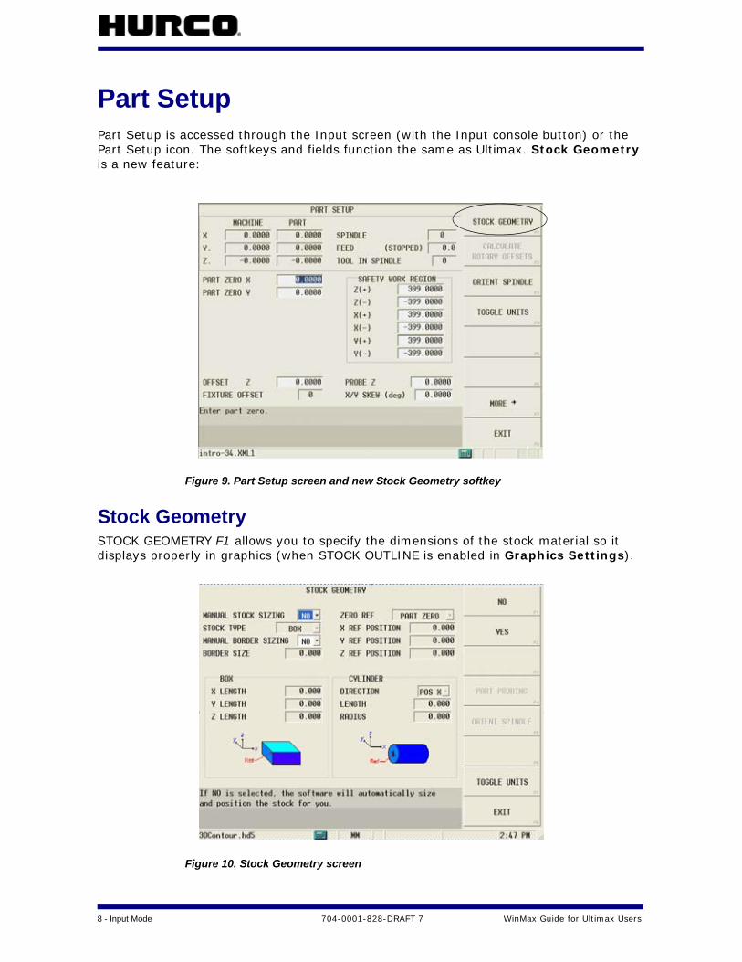
Part SetupPart Setup is accessed through the Input screen (with the Input console button) or the Part Setup icon. The softkeys and fields function the same as Ultimax. Stock Geometry is a new feature:
Figure 9. Part Setup screen and new Stock Geometry softkey
Stock GeometrySTOCK GEOMETRY F1 allows you to specify the dimensions of the stock material so it displays properly in graphics (when STOCK OUTLINE is enabled in Graphics Settings).
Figure 10. Stock Geometry screen

WinMax Guide for Ultimax Users 704-0001-828-DRAFT 7 Input Mode — 9
Fields on the Stock Geometry screen are:
• MANUAL STOCK SIZING—specify if you will manually set the stock dimensions
• NO—software will automatically size and position the stock. To calculate this, WinMax takes the diameter of the largest tool in the program and adds 7/10ths of that size to the stock diameter X and Y fields (with a minimum addition of .05).
• YES—enter the dimensions manually
• STOCK TYPE—specify BOX or CYLINDER
• BOX—enables settings for X length, Y length, Z length of stock box or cube
• CYLINDER—enables direction, length, and radius of cylinder
• MANUAL BORDER SIZING—specify if you will manually size the border (available only when MANUAL STOCK SIZING is set to NO)
• BORDER SIZE—specify stock border dimension (available only when MANUAL BORDER SIZING is set to YES)
• ZERO REF—coordinate system zero from which to reference the stock zero position
• X REF POSITION—locate the stock on X axis relative to the ZERO REF; can use Store Position or can be set to Part Zero with softkey
• Y REF POSITION—locate the stock on Y axis relative to the ZERO REF; can use Store Position or can be set to Part Zero with softkey
• Z REF POSITION—locate the stock on Z axis relative to the ZERO REF; can use Store Position or can be set to Part Zero with softkey
• BOX LENGTH (X, Y, Z)—specify lengths when MANUAL STOCK SIZING is YES and STOCK TYPE is BOX
• CYLINDER—set dimensions when MANUAL STOCk SIZING is YES and STOCK TYPE is CYLINDER
• DIRECTION—specify POS X, NEG X, POS Y, NEG Y, POS Z, or NEG Z
• LENGTH—specify length along axis from reference position
• RADIUS—specify stock radius
10 - Input Mode 704-0001-828-DRAFT 7 WinMax Guide for Ultimax Users
Part ProgrammingThere are several new Part Programming features in WinMax.
Tool Setup
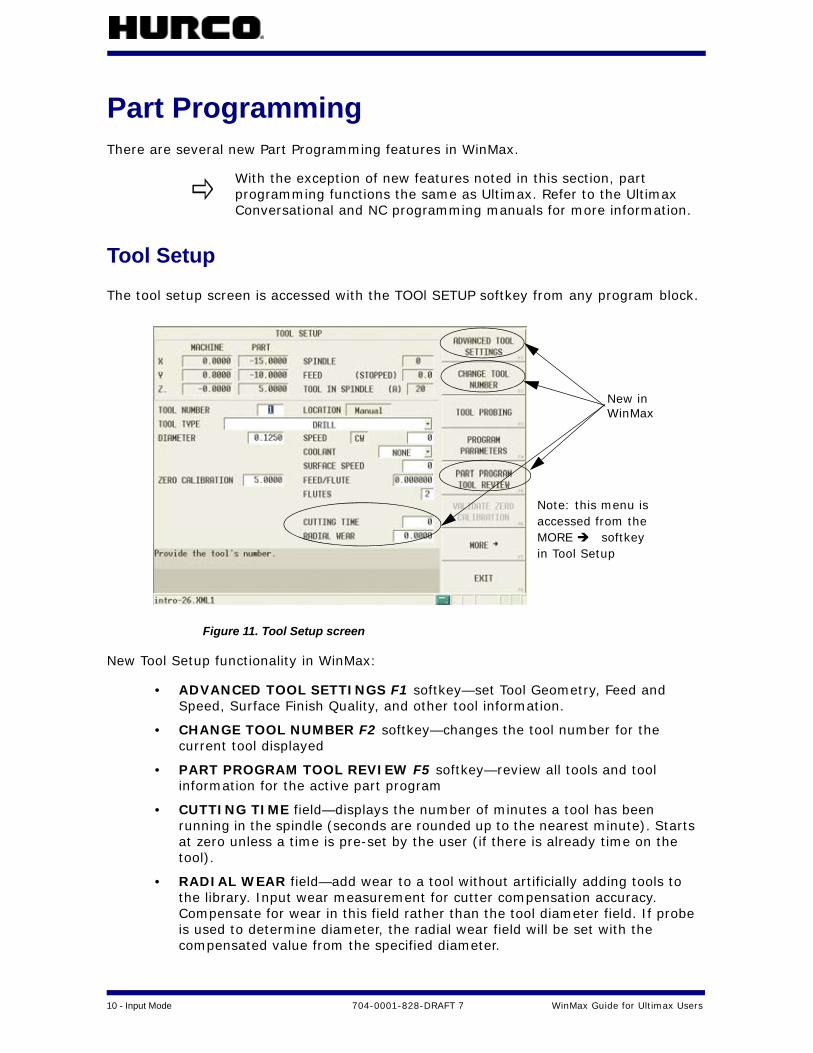
The tool setup screen is accessed with the TOOl SETUP softkey from any program block.
Figure 11. Tool Setup screen
New Tool Setup functionality in WinMax:
• ADVANCED TOOL SETTINGS F1 softkey—set Tool Geometry, Feed and Speed, Surface Finish Quality, and other tool information.
• CHANGE TOOL NUMBER F2 softkey—changes the tool number for the current tool displayed
• PART PROGRAM TOOL REVIEW F5 softkey—review all tools and tool information for the active part program
• CUTTING TIME field—displays the number of minutes a tool has been running in the spindle (seconds are rounded up to the nearest minute). Starts at zero unless a time is pre-set by the user (if there is already time on the tool).
• RADIAL WEAR field—add wear to a tool without artificially adding tools to the library. Input wear measurement for cutter compensation accuracy. Compensate for wear in this field rather than the tool diameter field. If probe is used to determine diameter, the radial wear field will be set with the compensated value from the specified diameter.
With the exception of new features noted in this section, part programming functions the same as Ultimax. Refer to the Ultimax Conversational and NC programming manuals for more information.
New inWinMax
Note: this menu isaccessed from theMORE softkeyin Tool Setup

WinMax Guide for Ultimax Users 704-0001-828-DRAFT 7 Input Mode — 11
• TOOL TYPES—WinMax supports the following tool types:
• Drill
• Tap (see “Taps” section below for more information)
• Boring Head
• End Mill
• Face Mill
• Ball End Mill
• Back Spotface Drill
• Probe
• Gun Drill
• Center Drill
• Chamfer Mill
• Bull Nose Mill
• Ream
• Spot Drill
• Forming tap
• Counter bore
• Counter Sink
• Keyseat Mill
• Thread mill
• Taper Radius End Mill
• Corner Round Mill
• Dove tail Mill
• Engraving Mill
12 - Input Mode 704-0001-828-DRAFT 7 WinMax Guide for Ultimax Users
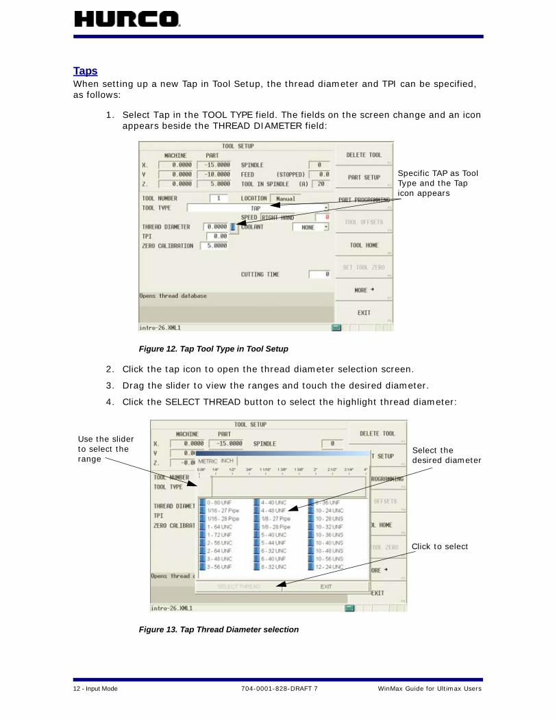
TapsWhen setting up a new Tap in Tool Setup, the thread diameter and TPI can be specified, as follows:
1. Select Tap in the TOOL TYPE field. The fields on the screen change and an icon appears beside the THREAD DIAMETER field:
Figure 12. Tap Tool Type in Tool Setup
2. Click the tap icon to open the thread diameter selection screen.
3. Drag the slider to view the ranges and touch the desired diameter.
4. Click the SELECT THREAD button to select the highlight thread diameter:
Figure 13. Tap Thread Diameter selection
Specific TAP as ToolType and the Tapicon appears
Use the sliderto select therange
Select thedesired diameter
Click to select

WinMax Guide for Ultimax Users 704-0001-828-DRAFT 7 Input Mode — 13
Tool SelectionIn WinMax, tools are added to part programs in two ways:
• Tool Number
• Select Tool from List
If the optional Tool & Material Library is in use, tool information is imported into the library when a program is initially opened in WinMax, and these imported tools are available to use in other part programs. See the “Tool and Material Library” section for more information. If the Tool & Material Library option is not used, the available tools are those that have been created in Tool Setup for the specific part program.
Tool NumberUse the TOOL NUMBER field to select a tool (one created in Tool Setup or from the Tool & Material Library, if that option is in use). Enter the tool number or the first digit of a numbered tool type group in the TOOl NUMBER field on the Tool Setup screen, as shown below:
Figure 14. Tool Number field in Tool Setup
Enter the first digit of a tool number in the TOOL NUMBER field and a list of all tools that begin with that digit appears. For example, entering a “1” will call up all tools numbered 100-199.
Tool Number

14 - Input Mode 704-0001-828-DRAFT 7 WinMax Guide for Ultimax Users
Select Tool from ListUse the following steps to select a tool using the SELECT TOOL FROM LIST F3 softkey:
1. In a program block screen, touch in the TOOL field and choose the SELECT TOOL FROM LIST F3 softkey:
Figure 15. Select Tool from List softkey
2. Locate the desired tool and select to highlight:
Figure 16. Selecting Tool from Tool Library
3. Touch the SELECT TOOL F1 softkey, which enters the tool into the data block or segment, as shown below:

WinMax Guide for Ultimax Users 704-0001-828-DRAFT 7 Input Mode — 15
Figure 17. Field is populated with selected tool
Position BlockIn addition to X and Y, WinMax has added a Z coordinate to set the location during a stop. This is only displayed if the STOP field is set to YES. The machine will move to the X, Y, and Z position at rapid and stop, requiring the operator to press start to resume the program.
Figure 18. Position Block
If Tool Type Checking is enabled, only tools that are suitable for the programmed operation can be selected.
When set to YES,Z coordinateappears

16 - Input Mode 704-0001-828-DRAFT 7 WinMax Guide for Ultimax Users
Milling BlocksFields are positioned for more intuitive access and steamlined programming:
• Tool information has been moved to the bottom of the screen
• Tabs display information for roughing and finishing tools
• SFQ tab allows the Surface Finish Quality to be set for specific data blocks, when the new SelectSurface Finish Quality option is enabled. See the SelectSurface Finish Quality section for more information.
Figure 19. Mill Frame Block
Tool informationis tabbed and
the bottom of thescreen
appears at

WinMax Guide for Ultimax Users 704-0001-828-DRAFT 7 Input Mode — 17
Mill ContoursThe INSERT SEGMENT BEFORE softkey has been moved to F7 position. PREVIOUS SEGMENT F1 and NEXT SEGMENT F2 softkeys have been added to aid navigation:
ENABLE BLEND MOVES is a new field in WinMax, and appears when MILLING TYPE is Left, Right, Profile Left, or Profile Right. The default is NO. YES will add an automatic lead-in and lead-out arc using Blend Offset and Blend Overlap parameters.
Figure 20. Mill Contour Block
LetteringHD3 lettering is the same as Ultimax, but new to WinMax is True-Type Lettering:
Figure 21. True-Type Lettering Program Block
18 - Input Mode 704-0001-828-DRAFT 7 WinMax Guide for Ultimax Users
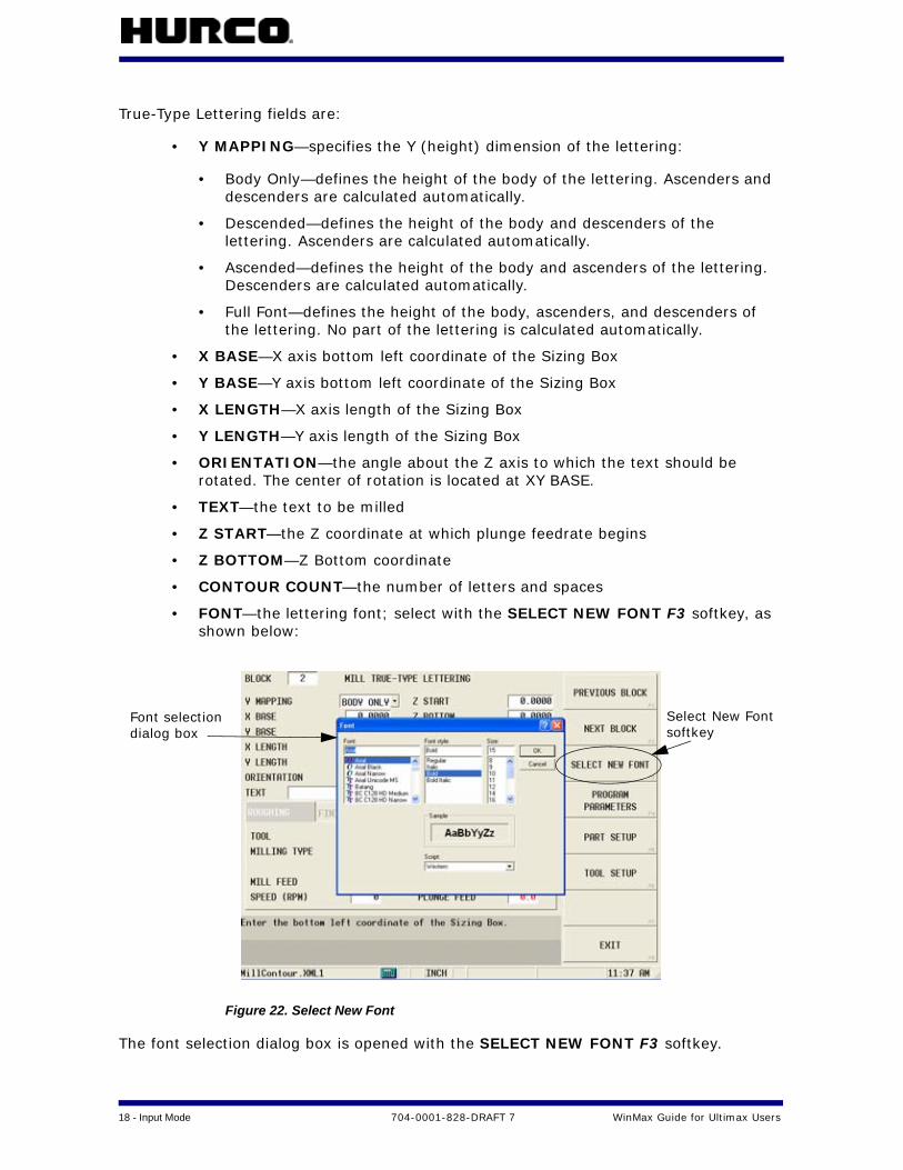
True-Type Lettering fields are:
• Y MAPPING—specifies the Y (height) dimension of the lettering:
• Body Only—defines the height of the body of the lettering. Ascenders and descenders are calculated automatically.
• Descended—defines the height of the body and descenders of the lettering. Ascenders are calculated automatically.
• Ascended—defines the height of the body and ascenders of the lettering. Descenders are calculated automatically.
• Full Font—defines the height of the body, ascenders, and descenders of the lettering. No part of the lettering is calculated automatically.
• X BASE—X axis bottom left coordinate of the Sizing Box
• Y BASE—Y axis bottom left coordinate of the Sizing Box
• X LENGTH—X axis length of the Sizing Box
• Y LENGTH—Y axis length of the Sizing Box
• ORIENTATION—the angle about the Z axis to which the text should be rotated. The center of rotation is located at XY BASE.
• TEXT—the text to be milled
• Z START—the Z coordinate at which plunge feedrate begins
• Z BOTTOM—Z Bottom coordinate
• CONTOUR COUNT—the number of letters and spaces
• FONT—the lettering font; select with the SELECT NEW FONT F3 softkey, as shown below:
Figure 22. Select New Font
The font selection dialog box is opened with the SELECT NEW FONT F3 softkey.
Select New Fontsoftkey
Font selectiondialog box
WinMax Guide for Ultimax Users 704-0001-828-DRAFT 7 Input Mode — 19
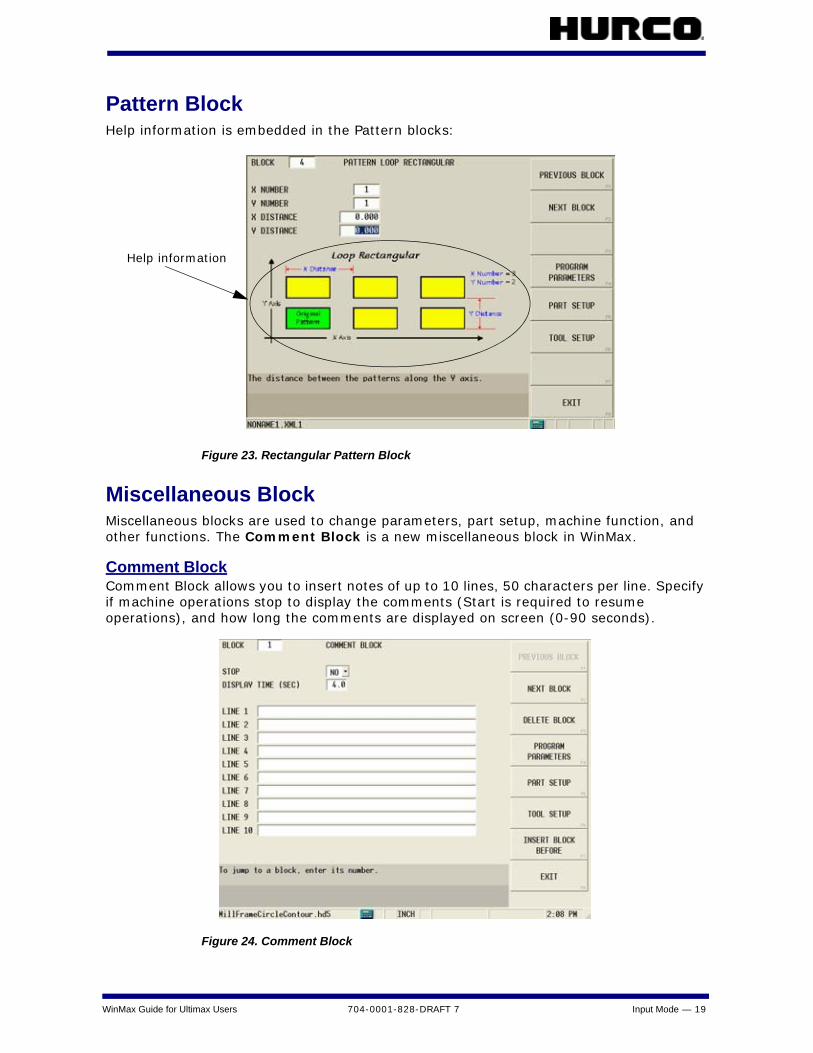
Pattern BlockHelp information is embedded in the Pattern blocks:
Figure 23. Rectangular Pattern Block
Miscellaneous BlockMiscellaneous blocks are used to change parameters, part setup, machine function, and other functions. The Comment Block is a new miscellaneous block in WinMax.
Comment BlockComment Block allows you to insert notes of up to 10 lines, 50 characters per line. Specify if machine operations stop to display the comments (Start is required to resume operations), and how long the comments are displayed on screen (0-90 seconds).
Figure 24. Comment Block
Help information
20 - Input Mode 704-0001-828-DRAFT 7 WinMax Guide for Ultimax Users
NC/Conversational MergeWinMax allows you to execute an ISNC G-code (NC) program from within a Conversational part program with NC/Conversational merge. G-code programs can be used and re-used within the Conversational program.
To invoke a G-Code program from within a Conversational part program, the program must be loaded in Program Manager. The first line of NC code following the percent (%) sign must contain the program number preceded by the letter “O” (not a zero) or a colon (:); for example, O1234 or :1234. There cannot be any other information on this line and “O” or “:” must be the first character. The program must end with an M99 to allow other Conversational program operations after the NC program is complete, as in the following program (O number and M99 are bolded for emphasis):
%
O5085
(#1 IS THE START ANGLE)
(#2 IS THE NUMBER OF GEAR TEETH)
(#3 IS THE OUTSIDE RADIUS)
(#11 IS THE INSIDE RADIUS)
(#4 IS THE GEAR CENTER PT X COORD)
(#5 IS THE GEAR CENTER PT Y COORD)
(#6 IS THE GEAR CENTER PT Z COORD)
(#19 IS THE TOOTH TO SKIP)
(#18 IS THE TOOTH RATIO)
/
T1 M06
M03G00G21G90X0Y0Z0S1800
(VARIABLE #4006 - INCHES/METRIC)
IF[#4006EQ20]GOTO10
IF[#4006EQ21]GOTO15
N10#850=25.4
GOTO20
N15#850=1.0
N20G0X-3Y-5
Y5
X8
Y-5
#30=[360.0/#2]
#31=0
#22=[#30*#18]
#23=#30-#22
#24=#11*#850
#25=#3*#850
#26=#20*#23
X#4 Y#5
G90G00G16X#25Y#1
WinMax Guide for Ultimax Users 704-0001-828-DRAFT 7 Input Mode — 21
G01Z-.25F20.
WHILE[#31LT#2]DO250
#1=[#1+[#22]]
G03G16X#25Y[#1]R#3
G01X#24Y[#1+#26]
#1=[#1+[#23]]
G03X#24Y[#1-#26]R#11
G01X#25Y[#1]
G15
N200#31=#31+1
N400END250
M99
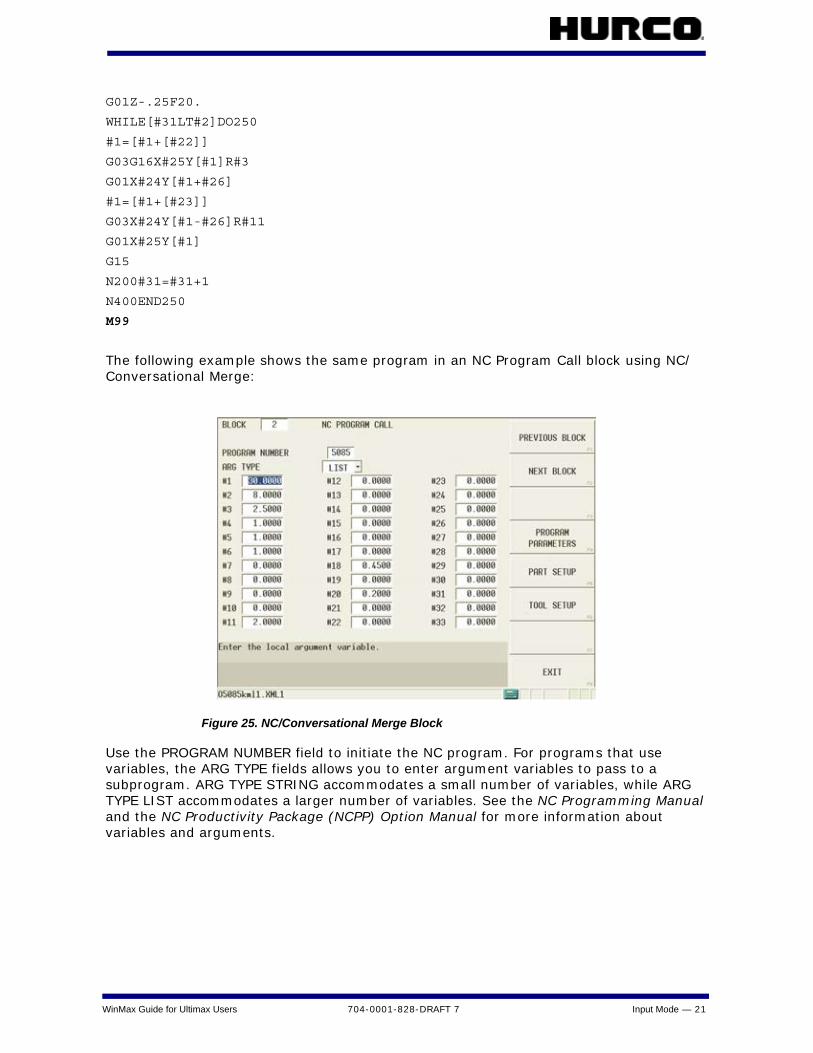
The following example shows the same program in an NC Program Call block using NC/Conversational Merge:
Figure 25. NC/Conversational Merge Block
Use the PROGRAM NUMBER field to initiate the NC program. For programs that use variables, the ARG TYPE fields allows you to enter argument variables to pass to a subprogram. ARG TYPE STRING accommodates a small number of variables, while ARG TYPE LIST accommodates a larger number of variables. See the NC Programming Manual and the NC Productivity Package (NCPP) Option Manual for more information about variables and arguments.

22 - Input Mode 704-0001-828-DRAFT 7 WinMax Guide for Ultimax Users
Swept SurfaceThe Swept Surface option in WinMax is based on 3-D Mold technology from Ultimax. It allows you to program draft angles for pocket or island walls with greater flexibility, including Spiral, Constant Z level, and Cusp Height cutting strategies.
Figure 26. Swept Surface Programming example

WinMax Guide for Ultimax Users 704-0001-828-DRAFT 7 Input Mode — 23
Program ParametersProgram parameters in WinMax are displayed on tabs for General 1, General 2, Milling 1, Milling 2, Holes, Probing, and Performance. The Performance tab in WinMax is active when the SelectSurface Finish Quality option is enabled. The programmer has the option to make changes to any or all of the program parameters and save them as user defaults. The user defaults and original WinMax defaults can be restored by using the appropriate softkey.
Figure 27. Program Parameters: Probing screen
Softkeys are:
• SAVE AS USER DEFAULTS F4—saves the selected field’s value as the user-defined default value
• RESTORE USER DEFAULTS F5—restores the user-defined values to a field that has been populated with other values
• RESTORE WINMAX DEFAULTS F6—restores the WinMax-defined values to a field that has been populated with other values
Probing ParametersProbing Parameters are new in WinMax, and include the following:
• AUTOMATIC TOOL MONITORING—indicate if tools that were calibrated with the probe should be automatically checked with each tool change
• ZERO CAL (LENGTH) TOLERANCE—the zero calibration (tool length) used when checking for a defective tool
• DIAMETER TOLERANCE—the diameter tolerance used when checking for a defective tool
Change Parameters program blocks load the user-defined parameters set in Program Parameters.

24 - Input Mode 704-0001-828-DRAFT 7 WinMax Guide for Ultimax Users
SelectSurface Finish QualitySurface Finish Quality (SFQ) is enabled with the SelectSurface Finish Quality option. SFQ parameters can be modified in either Conversational or NC programming. The default SFQ for roughing is 80 and finishing is 20. Recommended SFQ values are:
Table 1. Recommended SFQ values
SFQ in Conversational ProgrammingThere are three ways to adjust the SFQ in Conversational Programming:
• Program Parameters screen
• Individual data blocks
• Change Parameters block
Changing SFQ in Program ParametersYou can set the SFQ for all roughing and finishing tools until a Change Parameters block is specified or SFQ values are specified within the data block.
1. In Input mode, select the PROGRAM PARAMETERS F4 softkey.
Figure 28. Performance Tab in Program Parameters Screen
SFQ Desired Result
1-20 High precision parts /finishing
21-79 Good surface quality / finishing, semi-finishing
80-100 High throughput / roughing
If SelectSurface Finish Quality is not enabled, conversational roughing tools use SFQ of 80 and conversational finishing tools use SFQ of 20; NC default is 50.

WinMax Guide for Ultimax Users 704-0001-828-DRAFT 7 Input Mode — 25
2. Select the PERFORMANCE tab.
3. Enter a number in the field.
This adjusts SFQ for the entire program, unless changes are made to individual data blocks. If SelectSurface Finish Quality is not enabled, the values are set to 80 for roughing and 20 for finishing.
Changing SFQ in Individual Data BlocksSFQ can also be changed for individual Milling, Special, and Rotary blocks, using the SFQ tab in these data blocks. Values set on this tab override the values set in the Program Parameters screen.
Figure 29. Selecting SFQ in Data Block
Changing SFQ with Change Parameters BlockA Change Parameter block can also be used to specify SFQ within a part program. In a new block, select the Miscellaneous softkey, then the Change Parameters softkey, and click the Performance tab to adjust the Rough and Finish SFQ. This will change SFQ for any new block that follows.
Block Editor Modify SFQ allows changing of SFQ in multiple existing blocks.
26 - Input Mode 704-0001-828-DRAFT 7 WinMax Guide for Ultimax Users
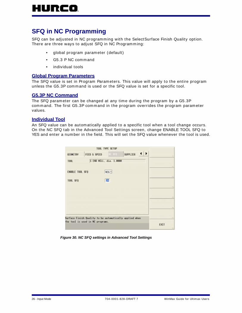
SFQ in NC ProgrammingSFQ can be adjusted in NC programming with the SelectSurface Finish Quality option. There are three ways to adjust SFQ in NC Programming:
• global program parameter (default)
• G5.3 P NC command
• individual tools
Global Program ParametersThe SFQ value is set in Program Parameters. This value will apply to the entire program unless the G5.3P command is used or the SFQ value is set for a specific tool.
G5.3P NC CommandThe SFQ parameter can be changed at any time during the program by a G5.3P command. The first G5.3P command in the program overrides the program parameter values.
Individual ToolAn SFQ value can be automatically applied to a specific tool when a tool change occurs. On the NC SFQ tab in the Advanced Tool Settings screen, change ENABLE TOOL SFQ to YES and enter a number in the field. This will set the SFQ value whenever the tool is used.
Figure 30. NC SFQ settings in Advanced Tool Settings

WinMax Guide for Ultimax Users 704-0001-828-DRAFT 7 Input Mode — 27
Import FunctionsImport Functions (known as Restore Functions in Ultimax) imports Part Setup, Tool Setup, Program Parameters, and/or Part Program information from an existing Conversational or NC program into the active part program, as follows:
1. Select the IMPORT FUNCTIONS F5 softkey from the Input screen.
2. Select the appropriate softkey for a Conversational or NC program.
3. Choose the program file from which components will be imported and select the LOAD F1 softkey.
4. Choose one or more operations from the list and select the BEGIN OPERATION F2 softkey.
• PART SETUP—imports the Part Setup from the selected program into the current part program
• TOOL SETUP—adds unique tools from the Tool Setup of the selected part program to the current tool setup on the machine. Tools are added as Manual; attempts to match to existing tools first.
• PROGRAM PARAMETERS—imports the Program Parameters from the selected program into the current part program
• PART PROGRAM—imports the part program from the selected program into the current part program
5. Select OK to continue the import operation.
Figure 31. Import Functions screen for Conversational
The imported components will replace the current components from the open program; they are not merged together.

28 - Input Mode 704-0001-828-DRAFT 7 WinMax Guide for Ultimax Users
Erase FunctionsErase functions erases (deletes) programs or components (part setup, tool setup, and program parameters).
Figure 32. Erase functions softkeys
New WinMax features are:
• ERASE PART SETUP F1—resets Part Setup to the default values.
• ERASE TOOL SETUP F2—deletes tools in Manual Tools, Auto Tools, and spindle.
• RESET PROGRAM PARAMETERS F3—resets Program Parameters to the default values.
• ERASE PROGRAM F4—deletes the part program data blocks but retains the program name.
• UNLOAD PROGRAM F5—removes program from the Program Manager, including the filename. This does the same function as CLOSE PROGRAM in the Program Manager.
ERASE TOOL SETUP deletes ALL tools from the control, and cannot be undone.

WinMax Guide for Ultimax Users 704-0001-828-DRAFT 7 Input Mode — 29
Program ManagerProgram Manager shows all part programs that are in the control’s memory to edit or run. Use the Program Manager menu to create, open, save, and close programs. Features of the Program Manager include:
• Ability to load more than one program at a time
• Ability to load Conversational and NC programs at the same time
• Ability to copy blocks from one program into another (blocks are copied in Program Review; Program Manager is used to switch between programs to facilitate copy and paste)
Figure 33. WinMax Program Manager
Program Manager softkeys are:
• NEW F1—creates a new part program. Choose the program type by selecting one of these softkeys:
• CONVERSATIONAL PROGRAM F1—creates a new conversational part program.
Sort the program list by Program Name or Path by selecting the corresponding header. Select the Program Name header once to sort the list alphabetically. Select the Program Name header again and sort the list in reverse alphabetical order.
List of programs
Unsaved programs
Program storage location
Snapshot of part
File type and description
Program in use lock
30 - Input Mode 704-0001-828-DRAFT 7 WinMax Guide for Ultimax Users
• NC PROGRAM F2—creates a new NC part program (extensions for NC part programs are determined by the NC dialect set in User Preferences).
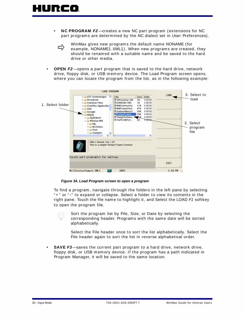
• OPEN F2—opens a part program that is saved to the hard drive, network drive, floppy disk, or USB memory device. The Load Program screen opens, where you can locate the program from the list, as in the following example:
Figure 34. Load Program screen to open a program
To find a program, navigate through the folders in the left pane by selecting “+” or “-” to expand or collapse. Select a folder to view its contents in the right pane. Touch the file name to highlight it, and Select the LOAD F1 softkey to open the program file.
• SAVE F3—saves the current part program to a hard drive, network drive, floppy disk, or USB memory device. If the program has a path indicated in Program Manager, it will be saved to the same location.
WinMax gives new programs the default name NONAME (for example, NONAME1.XML1). When new programs are created, they should be renamed with a suitable name and be saved to the hard drive or other media.
Sort the program list by File, Size, or Date by selecting the corresponding header. Programs with the same date will be sorted alphabetically.
Select the File header once to sort the list alphabetically. Select the File header again to sort the list in reverse alphabetical order.
1. Select folder
2. Select program
3. Select to load
file

WinMax Guide for Ultimax Users 704-0001-828-DRAFT 7 Input Mode — 31
• SAVE AS F4—allows the current part program to be saved with a different name, as a different file type, or in a different location. Also used to save files with the default NONAME program name. Type the program name in the File Name box and select the file type, as in the following example:
The following file types are available from the Save As Type drop-down list:
• .XML1—WinMax Mill conversational format
• .HD5—WinMax Desktop conversational format
• .HD3—Ultimax conversational format
• ISNC files
• CLOSE F5—opens a menu to close selected program or all programs.
• PROGRAM PROPERTIES F6—stores properties for the selected part program. See the following section, “Program Properties,” for more information.
• DISK OPERATIONS F7—opens the Disk Operations screen to browse available folders and files, and cut, copy, paste, rename, and delete files. See the following section, “Disk Operations” for more information.
• FTP MANAGER F8—displays external network connections (with the Ultinet option)
Hurco recommends the following storage areas:
• A:
• D:
• F:
• Network Places
32 - Input Mode 704-0001-828-DRAFT 7 WinMax Guide for Ultimax Users
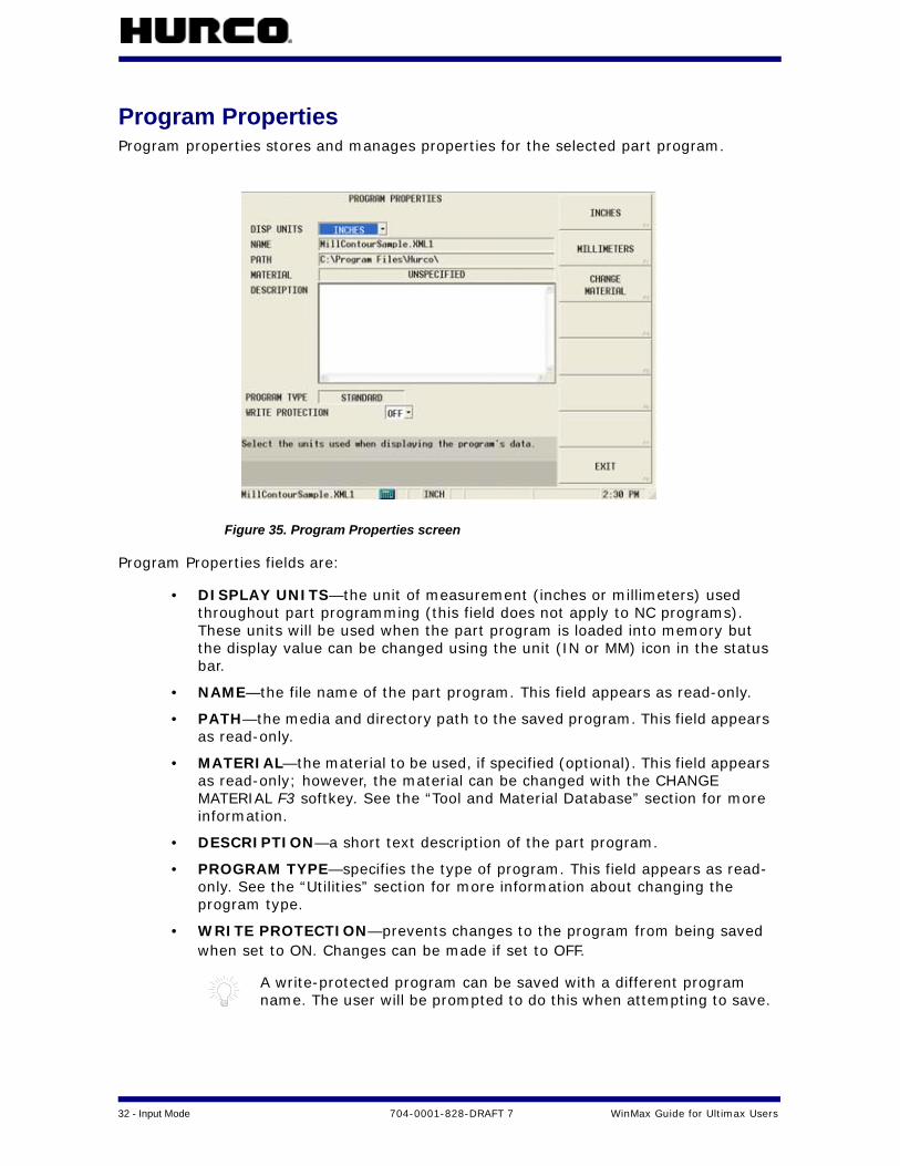
Program PropertiesProgram properties stores and manages properties for the selected part program.
Figure 35. Program Properties screen
Program Properties fields are:
• DISPLAY UNITS—the unit of measurement (inches or millimeters) used throughout part programming (this field does not apply to NC programs). These units will be used when the part program is loaded into memory but the display value can be changed using the unit (IN or MM) icon in the status bar.
• NAME—the file name of the part program. This field appears as read-only.
• PATH—the media and directory path to the saved program. This field appears as read-only.
• MATERIAL—the material to be used, if specified (optional). This field appears as read-only; however, the material can be changed with the CHANGE MATERIAL F3 softkey. See the “Tool and Material Database” section for more information.
• DESCRIPTION—a short text description of the part program.
• PROGRAM TYPE—specifies the type of program. This field appears as read-only. See the “Utilities” section for more information about changing the program type.
• WRITE PROTECTION—prevents changes to the program from being saved when set to ON. Changes can be made if set to OFF.
A write-protected program can be saved with a different program name. The user will be prompted to do this when attempting to save.

WinMax Guide for Ultimax Users 704-0001-828-DRAFT 7 Input Mode — 33
Disk OperationsDisk Operations displays available directories and files. Cut, copy, paste, rename, and delete program files from Disk Operations.
Figure 36. Disk Operations screen: directory highlighted view
When a directory is highlighted in the Directory Window, the softkeys are:
• CUT DIRECTORY F1—deletes the directory from one location to be pasted into another location
• COPY DIRECTORY F2—makes a copy of the directory (but does not delete) to be pasted into another location
• PASTE INTO DIRECTORY F3—pastes the directory or file that has been cut or copied. For example, to copy a directory and paste it into a new location:
1. Highlight the directory you wish to copy.
2. Select the COPY DIRECTORY F2 softkey.
3. Highlight the folder in which you wish to place the copied directory.
4. Select the PASTE INTO DIRECTORY F3 softkey.
• CREATE DIRECTORY F4—creates a new directory
• RENAME DIRECTORY F5—renames a directory
• DELETE DIRECTORY F6—removes the directory
• FTP MANAGER F7—displays the external network connections (with Ultinet option)
Directory Window Files Window

34 - Input Mode 704-0001-828-DRAFT 7 WinMax Guide for Ultimax Users
Figure 37. Disk Operations screen: files highlighted view
When a file is highlighted in the Files Window, the softkeys are:
• CUT F1—deletes the file from one location to be pasted into another location
• COPY F2—makes a copy of the file (but does not delete) to be pasted into another location
• PASTE F3—pastes the file that has been cut or copied. For example, to copy a file and paste it into a new location:
1. Highlight the file you wish to copy.
2. Select the COPY F2 softkey.
3. Highlight the folder in which you wish to place the copied file.
4. Select the PASTE F3 softkey.
• RENAME F4—renames the file
• DELETE F5—removes the file
• LOAD F6—loads the file into the Program Manager
• FTP MANAGER F7—displays the external network connections (with Ultinet option)
WinMax Guide for Ultimax Users 704-0001-828-DRAFT 7 Tool and Material Library — 35
TOOL AND MATERIAL LIBRARYTool information can be stored independent of the part program data using the Tool & Material Library option. Program-specific tool information (such as feed rate and speed) created for one program can be reused when tools are selected from the library for a subsequent program.
Tool ManagementTool Management screens are accessed in Manual Mode with the TOOL MANAGEMENT F1 softkey. They provide the following information:
• Spindle—shows the tool located in the machine’s spindle.
• Auto—lists the tools that are in the machine’s tool magazine.
• Manual—lists the tools that may be utilized on the machine but are not currently in the machine’s magazine or spindle. The Manual tab is active only with the Tool and Material Library option.
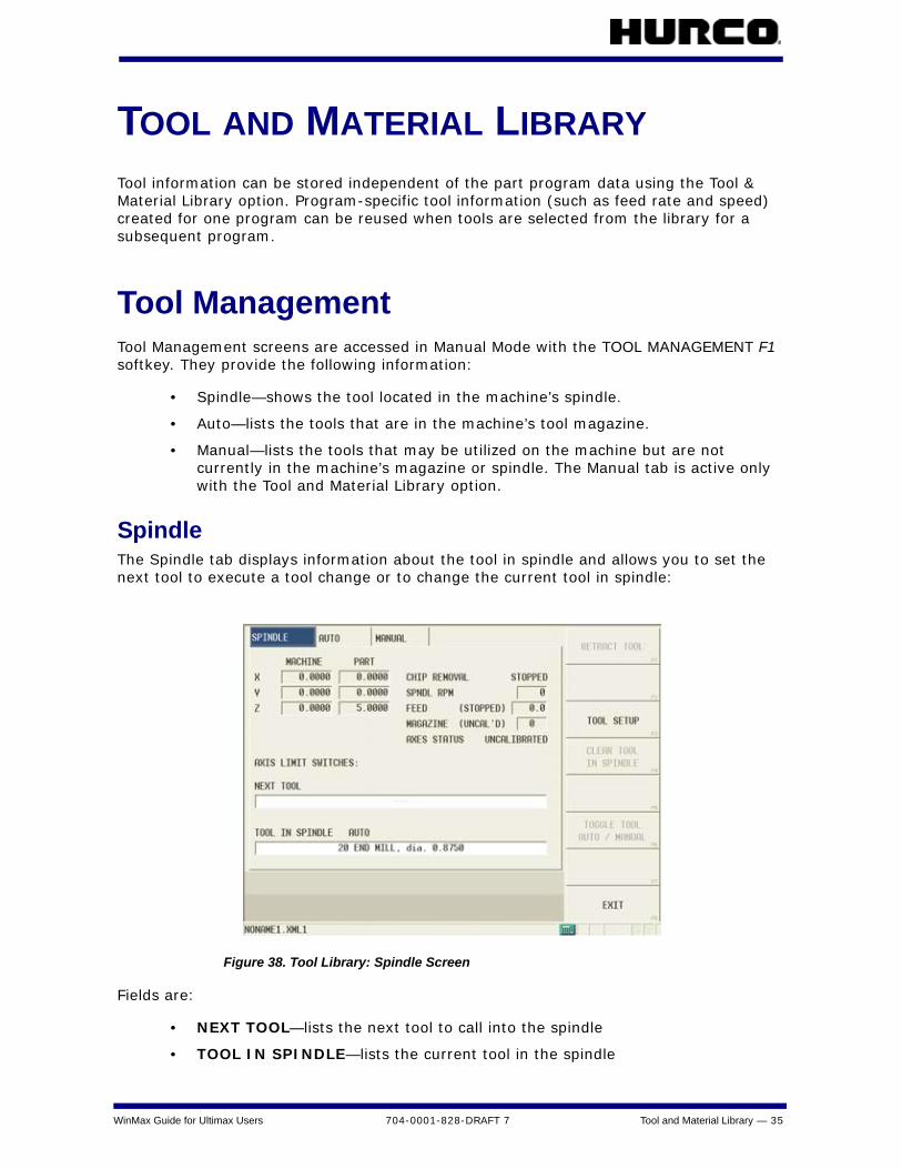
SpindleThe Spindle tab displays information about the tool in spindle and allows you to set the next tool to execute a tool change or to change the current tool in spindle:
Figure 38. Tool Library: Spindle Screen
Fields are:
• NEXT TOOL—lists the next tool to call into the spindle
• TOOL IN SPINDLE—lists the current tool in the spindle
36 - Tool and Material Library 704-0001-828-DRAFT 7 WinMax Guide for Ultimax Users
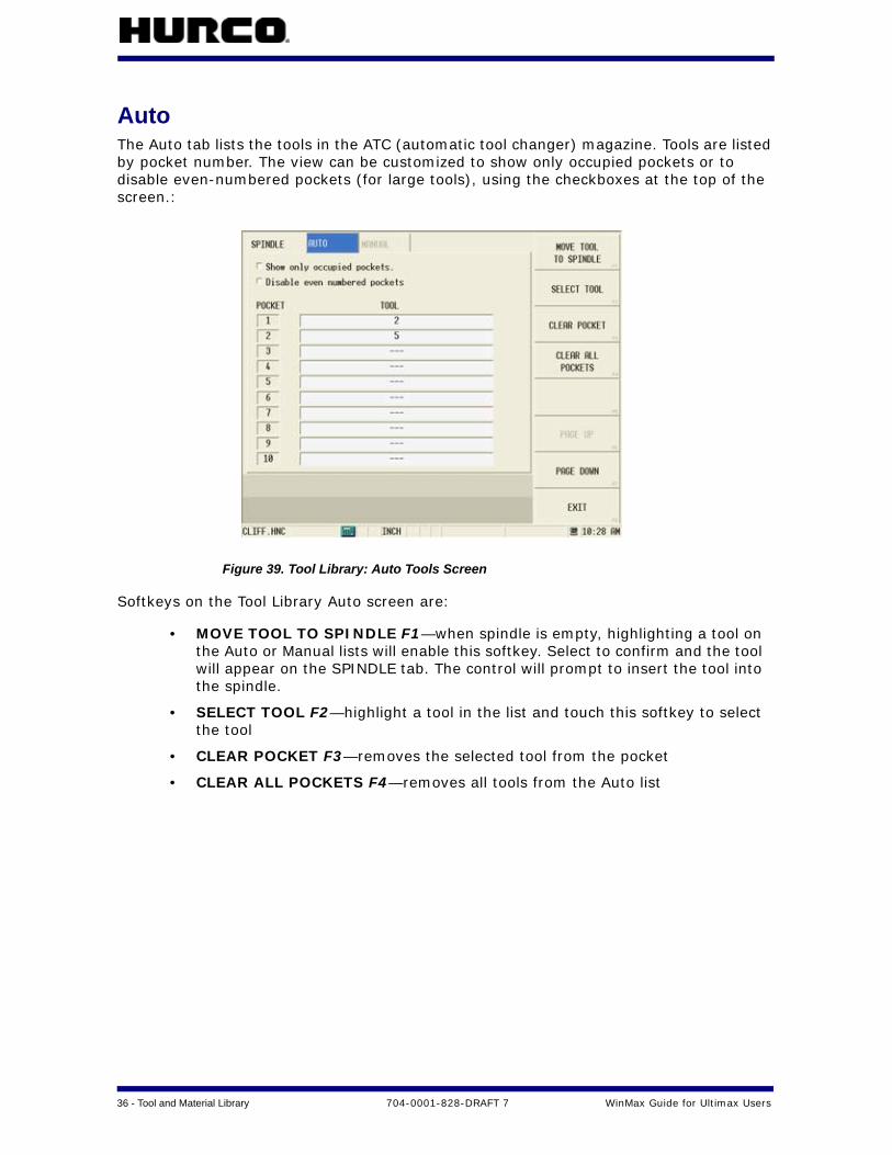
AutoThe Auto tab lists the tools in the ATC (automatic tool changer) magazine. Tools are listed by pocket number. The view can be customized to show only occupied pockets or to disable even-numbered pockets (for large tools), using the checkboxes at the top of the screen.:
Figure 39. Tool Library: Auto Tools Screen
Softkeys on the Tool Library Auto screen are:
• MOVE TOOL TO SPINDLE F1—when spindle is empty, highlighting a tool on the Auto or Manual lists will enable this softkey. Select to confirm and the tool will appear on the SPINDLE tab. The control will prompt to insert the tool into the spindle.
• SELECT TOOL F2—highlight a tool in the list and touch this softkey to select the tool
• CLEAR POCKET F3—removes the selected tool from the pocket
• CLEAR ALL POCKETS F4—removes all tools from the Auto list
WinMax Guide for Ultimax Users 704-0001-828-DRAFT 7 Tool and Material Library — 37
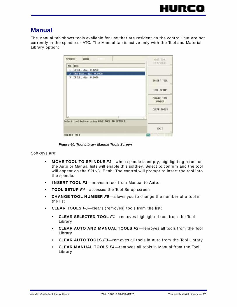
ManualThe Manual tab shows tools available for use that are resident on the control, but are not currently in the spindle or ATC. The Manual tab is active only with the Tool and Material Library option:
Figure 40. Tool Library Manual Tools Screen
Softkeys are:
• MOVE TOOL TO SPINDLE F1—when spindle is empty, highlighting a tool on the Auto or Manual lists will enable this softkey. Select to confirm and the tool will appear on the SPINDLE tab. The control will prompt to insert the tool into the spindle.
• INSERT TOOL F3—moves a tool from Manual to Auto:
• TOOL SETUP F4—accesses the Tool Setup screen
• CHANGE TOOL NUMBER F5—allows you to change the number of a tool in the list
• CLEAR TOOLS F6—clears (removes) tools from the list:
• CLEAR SELECTED TOOL F1—removes highlighted tool from the Tool Library
• CLEAR AUTO AND MANUAL TOOLS F2—removes all tools from the Tool Library
• CLEAR AUTO TOOLS F3—removes all tools in Auto from the Tool Library
• CLEAR MANUAL TOOLS F4—removes all tools in Manual from the Tool Library
38 - Tool and Material Library 704-0001-828-DRAFT 7 WinMax Guide for Ultimax Users
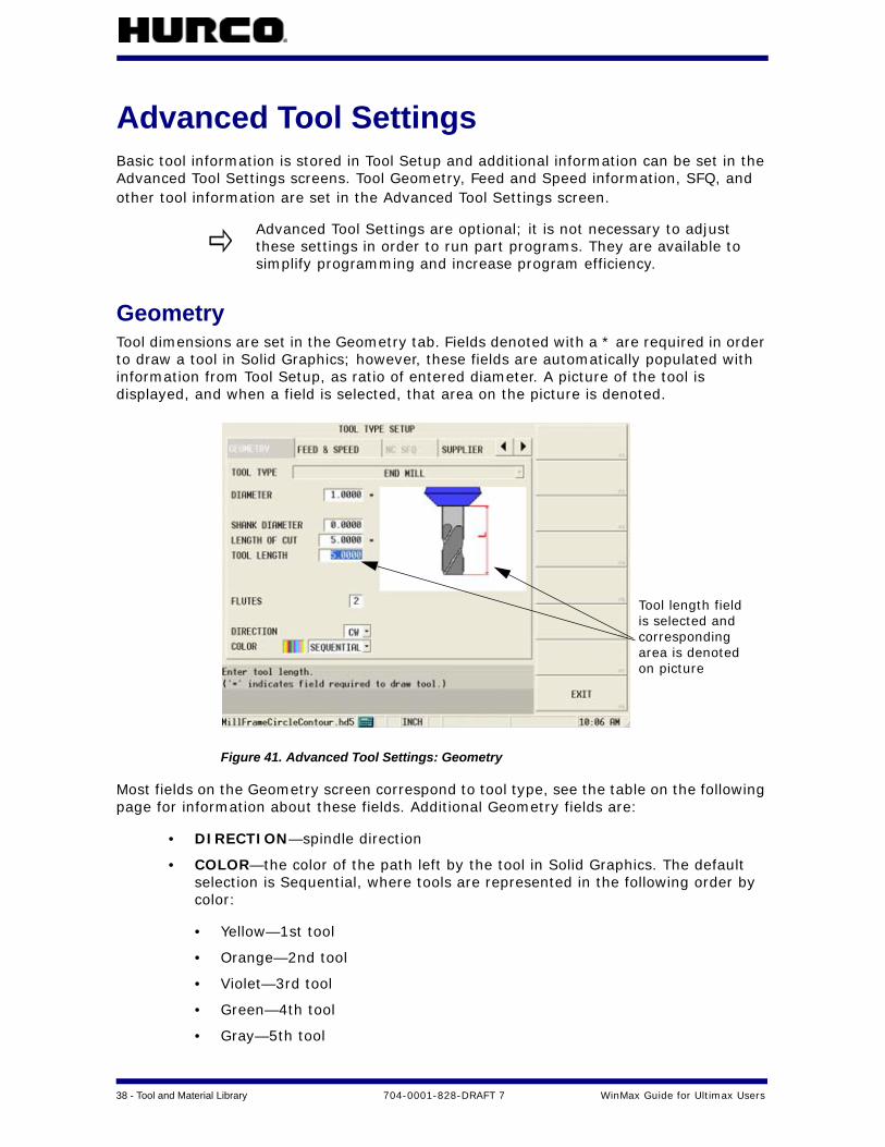
Advanced Tool SettingsBasic tool information is stored in Tool Setup and additional information can be set in the Advanced Tool Settings screens. Tool Geometry, Feed and Speed information, SFQ, and other tool information are set in the Advanced Tool Settings screen.
GeometryTool dimensions are set in the Geometry tab. Fields denoted with a * are required in order to draw a tool in Solid Graphics; however, these fields are automatically populated with information from Tool Setup, as ratio of entered diameter. A picture of the tool is displayed, and when a field is selected, that area on the picture is denoted.
Figure 41. Advanced Tool Settings: Geometry
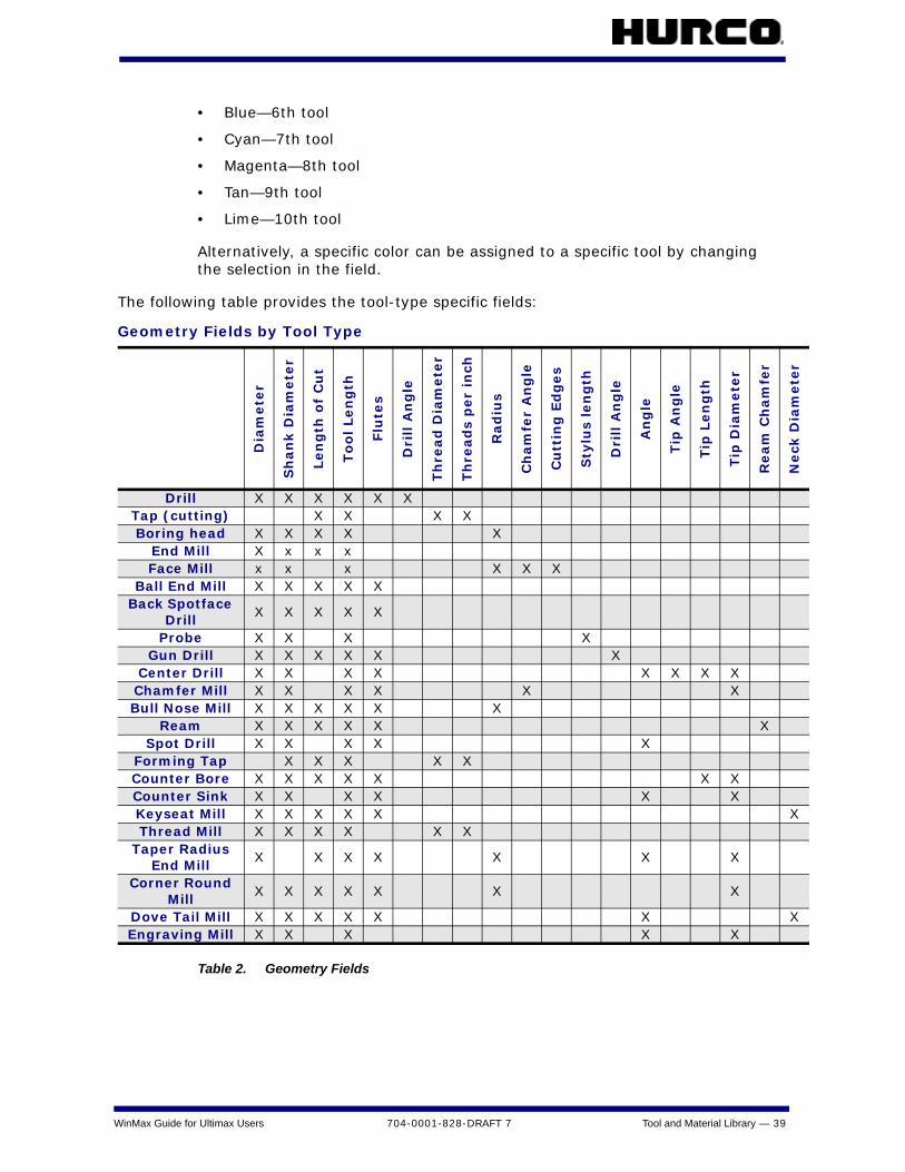
Most fields on the Geometry screen correspond to tool type, see the table on the following page for information about these fields. Additional Geometry fields are:
• DIRECTION—spindle direction
• COLOR—the color of the path left by the tool in Solid Graphics. The default selection is Sequential, where tools are represented in the following order by color:
• Yellow—1st tool
• Orange—2nd tool
• Violet—3rd tool
• Green—4th tool
• Gray—5th tool
Advanced Tool Settings are optional; it is not necessary to adjust these settings in order to run part programs. They are available to simplify programming and increase program efficiency.
Tool length fieldis selected andcorresponding area is denoted on picture
WinMax Guide for Ultimax Users 704-0001-828-DRAFT 7 Tool and Material Library — 39
• Blue—6th tool
• Cyan—7th tool
• Magenta—8th tool
• Tan—9th tool
• Lime—10th tool
Alternatively, a specific color can be assigned to a specific tool by changing the selection in the field.
The following table provides the tool-type specific fields:
Table 2. Geometry Fields
Geometry Fields by Tool Type
Dia
mete
r
Sh
an
k D
iam
ete
r
Len
gth
of
Cu
t
To
ol Len
gth
Flu
tes
Dri
ll A
ng
le
Th
read
Dia
mete
r
Th
read
s p
er
inch
Rad
ius
Ch
am
fer
An
gle
Cu
ttin
g E
dg
es
Sty
lus
len
gth
Dri
ll A
ng
le
An
gle
Tip
An
gle
Tip
Len
gth
Tip
Dia
mete
r
Ream
Ch
am
fer
Neck
Dia
mete
r
Drill X X X X X XTap (cutting) X X X XBoring head X X X X X
End Mill X x x xFace Mill x x x X X X
Ball End Mill X X X X XBack Spotface
DrillX X X X X
Probe X X X XGun Drill X X X X X X
Center Drill X X X X X X X XChamfer Mill X X X X X XBull Nose Mill X X X X X X
Ream X X X X X XSpot Drill X X X X X
Forming Tap X X X X XCounter Bore X X X X X X XCounter Sink X X X X X XKeyseat Mill X X X X X XThread Mill X X X X X X
Taper Radius End Mill
X X X X X X X
Corner Round Mill
X X X X X X X
Dove Tail Mill X X X X X X XEngraving Mill X X X X X

40 - Tool and Material Library 704-0001-828-DRAFT 7 WinMax Guide for Ultimax Users
Feed and Speed
Feed and Speed settings are carried over from Tool Setup or can be specified in the Feed and Speed tab for specific tool and material combinations in a part program. Choose one of the materials from the work material list for a specific tool and enter the feeds and speeds for both roughing and finishing for that tool and work material combination. This information is saved in the Tool and Material Library and can be utilized in future part programs without re-entering the speeds and feeds: When the Program Parameters for a part program specify a work material, the tool number will recall the feed and speed for that material.
Figure 42. Advanced Tool Settings: Feed and Speed
Roughing and finishing tool parameters can be specified. Fields are:
• SURFACE SPEED—set in Tool Setup, or calculated from speed and diameter
• CHIPLOAD—set in Tool Setup, or calculated based on feeds and flutes
• MAX DEPTH—set maximum depth of cut (optional)
• COOLANT—select coolant type: none, primary, secondary, or both
• SPEED—calculated value or may be user-defined
• FEED—calculated value or may be user-defined
• PECK DEPTH—set peck depth
• PLUNGE FEED—set plunge feed, or calculated based on Feed Per Rev for
Feed and Speed in Advanced Tool Settings is available only with the Tool and Material Library option.
Regardless of the material set in the Feed and Speed tab, the main Tool Setup screen will always display feeds and speeds for “Unspecified” material.
Specify workmaterial
SpecifyRoughing &Finishing
Speed and Feedare calculated or
can be specifiedin these fields
WinMax Guide for Ultimax Users 704-0001-828-DRAFT 7 Tool and Material Library — 41
hole-making tools
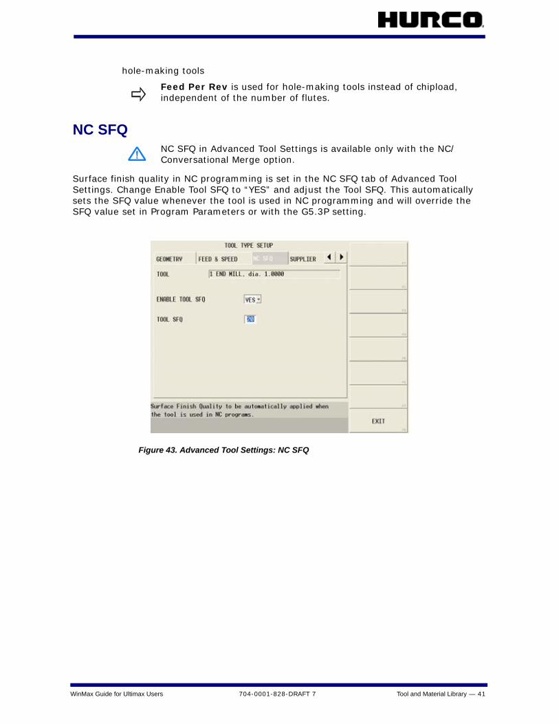
NC SFQ
Surface finish quality in NC programming is set in the NC SFQ tab of Advanced Tool Settings. Change Enable Tool SFQ to “YES” and adjust the Tool SFQ. This automatically sets the SFQ value whenever the tool is used in NC programming and will override the SFQ value set in Program Parameters or with the G5.3P setting.
Figure 43. Advanced Tool Settings: NC SFQ
Feed Per Rev is used for hole-making tools instead of chipload, independent of the number of flutes.
NC SFQ in Advanced Tool Settings is available only with the NC/Conversational Merge option.
42 - Tool and Material Library 704-0001-828-DRAFT 7 WinMax Guide for Ultimax Users
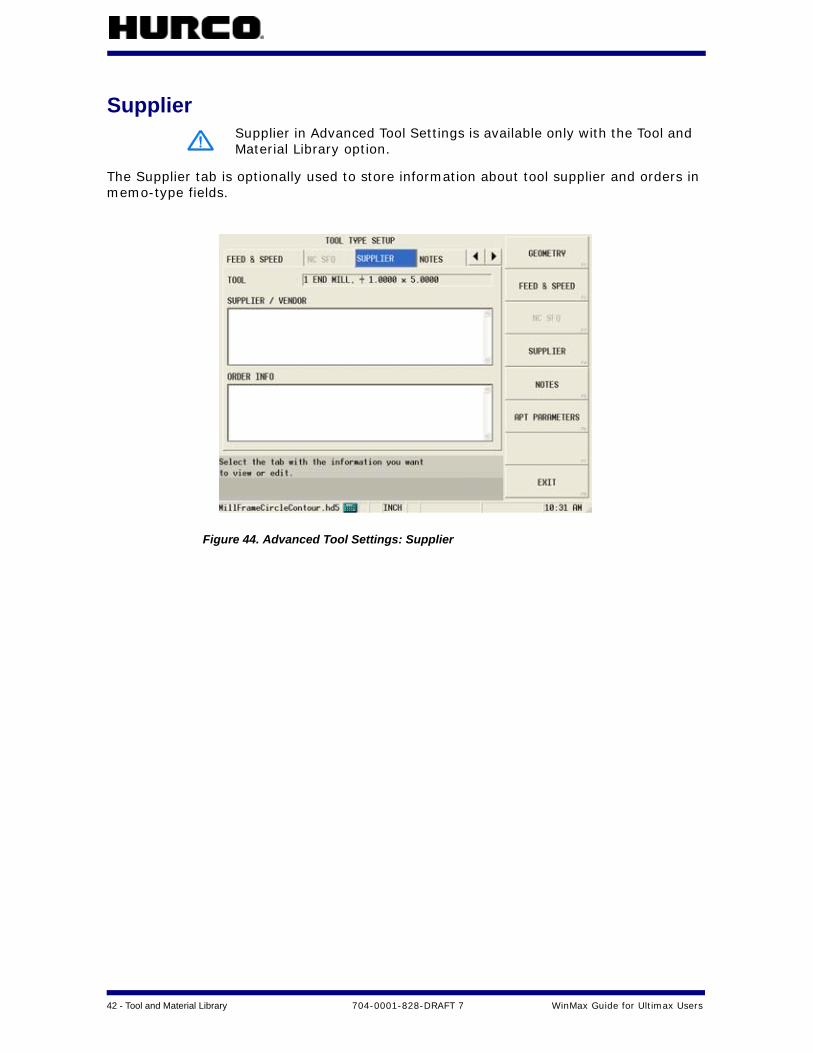
Supplier
The Supplier tab is optionally used to store information about tool supplier and orders in memo-type fields.
Figure 44. Advanced Tool Settings: Supplier
Supplier in Advanced Tool Settings is available only with the Tool and Material Library option.
WinMax Guide for Ultimax Users 704-0001-828-DRAFT 7 Tool and Material Library — 43
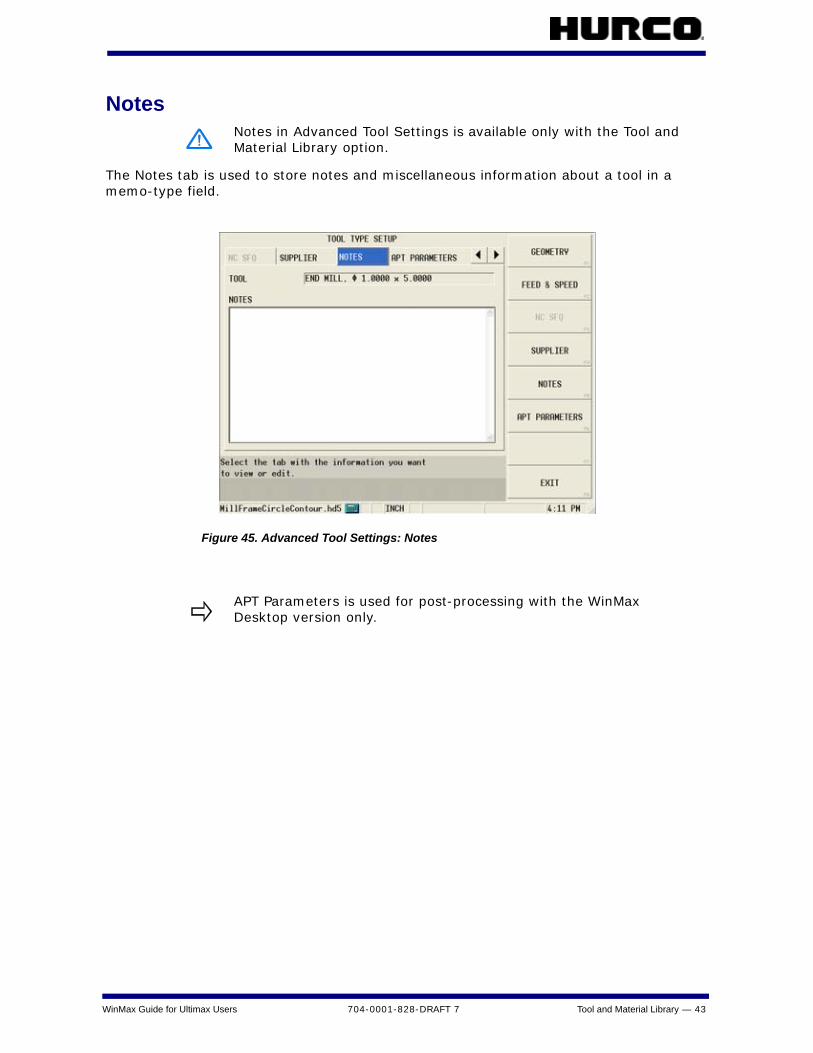
Notes
The Notes tab is used to store notes and miscellaneous information about a tool in a memo-type field.
Figure 45. Advanced Tool Settings: Notes
Notes in Advanced Tool Settings is available only with the Tool and Material Library option.
APT Parameters is used for post-processing with the WinMax Desktop version only.

44 - Tool and Material Library 704-0001-828-DRAFT 7 WinMax Guide for Ultimax Users
Tool and Material DatabaseThe Tool and Material Database is available when the Tool & Material Library option is enabled. It is accessed in Auxiliary Mode. Tool and material information can be entered and stored in the database. The materials entered into the database are available in the work material list located on the Feed and Speed tab in Tool Type Setup/Advanced Tool Settings. This information is saved in the material database and can be utilized in future part programs without re-entering the speeds and feeds.
To add a tool to the database:
1. Select the TOOLS tab.
2. Select ADD TOOL F1 softkey.
3. Enter the tool information in the fields. See the “Advanced Tool Settings” section for more information about these fields.
Figure 46. Tool and Material Database screen:Tools tab
Softkeys on the TOOLS tab are:
• ADD TOOL F1—add a tool to the tool list in Tool and Material Library
• EDIT TOOL F2—opens the highlighted tool to be edited in Tool Setup
• REMOVE TOOL F3—delete a tool from the database
• RELOAD DATABASE F4—TBD
• DATABASE SOURCE F7—TBD

WinMax Guide for Ultimax Users 704-0001-828-DRAFT 7 Tool and Material Library — 45
To add a material to the database:
1. Select the MATERIALS tab.
2. Select the ADD MATERIAL F1 softkey.
3. Type the name of the material in the NAME field.
4. Add any notes in the NOTES field.
5. Select the SAVE F1 softkey.
Figure 47. Tool and Material Database screen: Materials tab
Softkeys on the MATERIALS tab are:
• ADD MATERIAL F1—add a new material to the database
• EDIT MATERIAL F2—change the specifications of a material in the database
• DELETE MATERIAL F3—delete a material from the database
• RELOAD DATABASE F4—TBD
• SELECT MATERIAL FOR PART PROGRAM F5—uses the highlighted material in the current part program
• DATABASE SOURCE F7—TBD
46 - Review Mode 704-0001-828-DRAFT 7 WinMax Guide for Ultimax Users
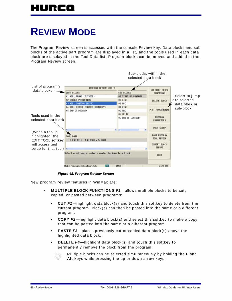
REVIEW MODEThe Program Review screen is accessed with the console Review key. Data blocks and sub blocks of the active part program are displayed in a list, and the tools used in each data block are displayed in the Tool Data list. Program blocks can be moved and added in the Program Review screen.
Figure 48. Program Review Screen
New program review features in WinMax are:
• MULTIPLE BLOCK FUNCTIONS F1—allows multiple blocks to be cut, copied, or pasted between programs:
• CUT F1—highlight data block(s) and touch this softkey to delete from the current program. Block(s) can then be pasted into the same or a different program.
• COPY F2—highlight data block(s) and select this softkey to make a copy that can be pasted into the same or a different program.
• PASTE F3—places previously cut or copied data block(s) above the highlighted data block.
• DELETE F4—highlight data block(s) and touch this softkey to permanently remove the block from the program.
Multiple blocks can be selected simultaneously by holding the F and Alt keys while pressing the up or down arrow keys.
List of program’s data blocks
Sub-blocks within the selected data block
Select to jumpto selected
sub-blockdata block or
(When a tool is
will access tool
highlighted, theEDIT TOOL softkey
setup for that tool)
Tools used in theselected data block
WinMax Guide for Ultimax Users 704-0001-828-DRAFT 7 Review Mode — 47
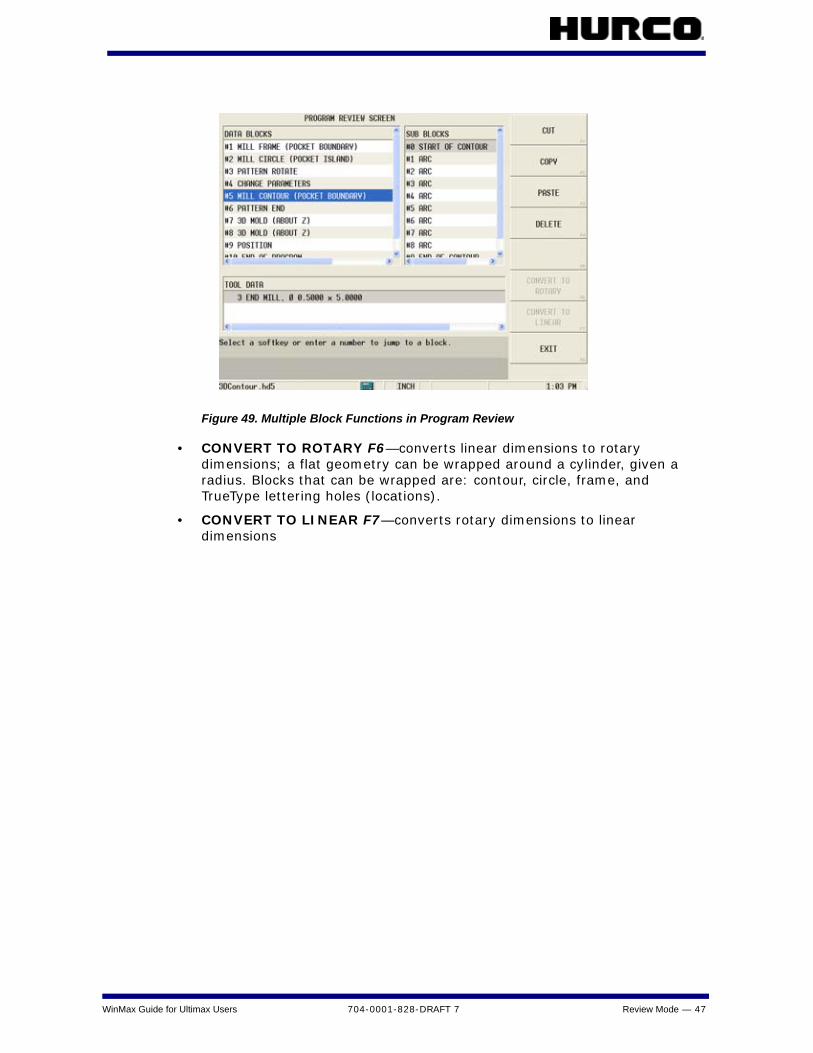
Figure 49. Multiple Block Functions in Program Review
• CONVERT TO ROTARY F6—converts linear dimensions to rotary dimensions; a flat geometry can be wrapped around a cylinder, given a radius. Blocks that can be wrapped are: contour, circle, frame, and TrueType lettering holes (locations).
• CONVERT TO LINEAR F7—converts rotary dimensions to linear dimensions
48 - Review Mode 704-0001-828-DRAFT 7 WinMax Guide for Ultimax Users
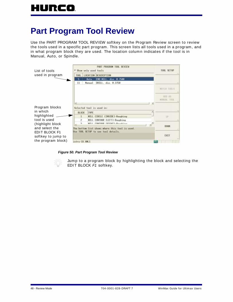
Part Program Tool ReviewUse the PART PROGRAM TOOL REVIEW softkey on the Program Review screen to review the tools used in a specific part program. This screen lists all tools used in a program, and in what program block they are used. The location column indicates if the tool is in Manual, Auto, or Spindle.
Figure 50. Part Program Tool Review
Jump to a program block by highlighting the block and selecting the EDIT BLOCK F1 softkey.
List of toolsused in program
Program blocks in whichhighlightedtool is used(highlight blockand select theEDIT BLOCK F1softkey to jump to the program block)
WinMax Guide for Ultimax Users 704-0001-828-DRAFT 7 Review Mode — 49
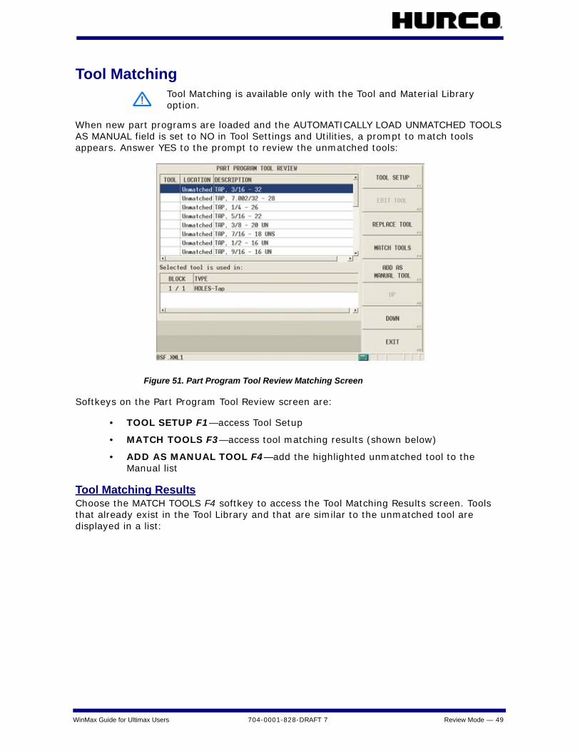
Tool Matching
When new part programs are loaded and the AUTOMATICALLY LOAD UNMATCHED TOOLS AS MANUAL field is set to NO in Tool Settings and Utilities, a prompt to match tools appears. Answer YES to the prompt to review the unmatched tools:
Figure 51. Part Program Tool Review Matching Screen
Softkeys on the Part Program Tool Review screen are:
• TOOL SETUP F1—access Tool Setup
• MATCH TOOLS F3—access tool matching results (shown below)
• ADD AS MANUAL TOOL F4—add the highlighted unmatched tool to the Manual list
Tool Matching ResultsChoose the MATCH TOOLS F4 softkey to access the Tool Matching Results screen. Tools that already exist in the Tool Library and that are similar to the unmatched tool are displayed in a list:
Tool Matching is available only with the Tool and Material Library option.

50 - Review Mode 704-0001-828-DRAFT 7 WinMax Guide for Ultimax Users
Figure 52. Tool Matching Results
Unmatched tools
List of similar toolsin Tool Library (list
Difference intool diameterfrom
corresponds to thehighlighted tool)
unmatchedtool
WinMax Guide for Ultimax Users 704-0001-828-DRAFT 7 Auxiliary Mode — 51
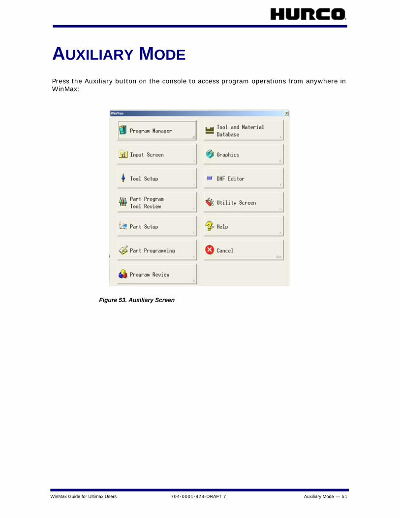
AUXILIARY MODEPress the Auxiliary button on the console to access program operations from anywhere in WinMax:
Figure 53. Auxiliary Screen

52 - Auxiliary Mode 704-0001-828-DRAFT 7 WinMax Guide for Ultimax Users
UtilitiesSelect the Utility Screen icon in Auxiliary to access the Utilities screen, shown below:
Figure 54. Utilities Screen
The following softkeys provide access to WinMax utilities:
System Configuration F1The SYSTEM CONFIGURATION F1 softkey on the Utilities screen displays machine, control, and software information:
Figure 55. System Configuration

WinMax Guide for Ultimax Users 704-0001-828-DRAFT 7 Auxiliary Mode — 53
Softkeys on the System Configuration screen are:
• DATE /TIME SETTINGS F1—change date and time settings
• DISPLAY WINMAX CONFIGURATION F3—change WinMax configuration settings
• DISPAY MACHINE SPECIFICATIONS F4—change machine specifications
• UPGRADE MOTION CONTROL FIRMWARE F5—upgrade firmware
• BACKUP CONFIG & MACHINE FILES F6
• RESTORE CONFIG & MACHINE FILES F7
User Preferences F2The USER PREFERENCES F2 softkey on the Utilities screen provides access to the following settings:
Figure 56. User Preference Screen in Utilities

54 - Auxiliary Mode 704-0001-828-DRAFT 7 WinMax Guide for Ultimax Users
• USER INTERFACE SETTINGS F1 softkey:
Figure 57. User Interface Settings in Utilities
Fields are:
• APPLICATION FONT SIZE—size of text displayed by the application in lists (for example, in Program Manager); default is Large. This field is inactive in WinMax Mill (active in WinMax desktop).
• SOFTKEY MENU POSITION—positions the softkey menu to the right or left of the screen; default is Right.
• EDIT MODE—select either Ultimax Classic (default) or Windows Dialog. For example, Ultimax Classic requires the Enter key to change the value of a data field, while Windows Dialog will accept a number by pressing the Down arrow.
• ENABLE PROJECT RESTORE—resets previously loaded programs when the application is started after a shutdown; default is No.
• SHOW ALL FILE TYPES—view all file extensions when opening files; default is No (only displays XML1, HD3, HD5, FNC, HNC, and NC file types).
• SCREENSAVER TIMEOUT—set screensaver timeout in minutes (range is 1-30 minutes); default is 10.
• LIST CONTROL ROWS—select the appearance of list controls; default is Lines.
• LIST ICON SIZE—changes the size of icons in lists; default is Small.
• WARN BEFORE SAVING IN OLD FORMAT—specify if WinMax should should warn that information may be lost when saving a program as HD3.
WinMax Guide for Ultimax Users 704-0001-828-DRAFT 7 Auxiliary Mode — 55
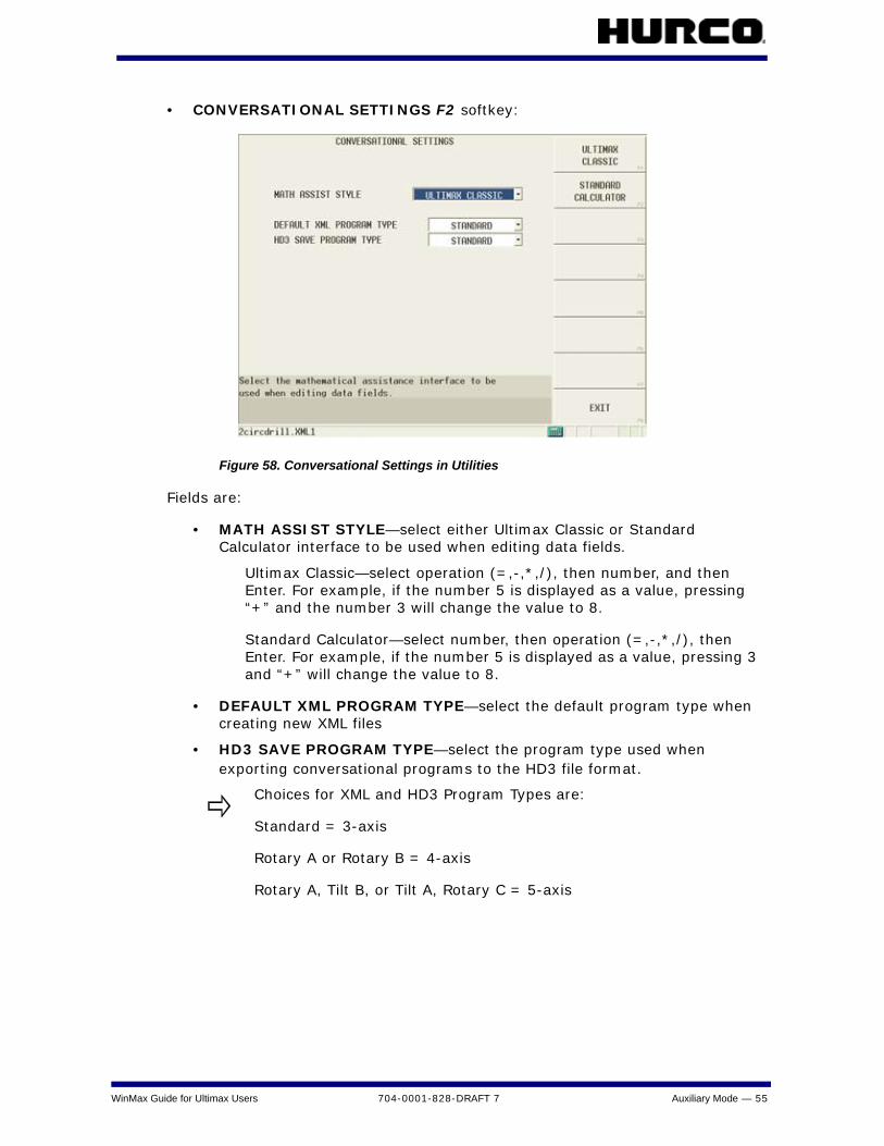
• CONVERSATIONAL SETTINGS F2 softkey:
Figure 58. Conversational Settings in Utilities
Fields are:
• MATH ASSIST STYLE—select either Ultimax Classic or Standard Calculator interface to be used when editing data fields.
Ultimax Classic—select operation (=,-,*,/), then number, and then Enter. For example, if the number 5 is displayed as a value, pressing “+” and the number 3 will change the value to 8.
Standard Calculator—select number, then operation (=,-,*,/), then Enter. For example, if the number 5 is displayed as a value, pressing 3 and “+” will change the value to 8.
• DEFAULT XML PROGRAM TYPE—select the default program type when creating new XML files
• HD3 SAVE PROGRAM TYPE—select the program type used when exporting conversational programs to the HD3 file format.
Choices for XML and HD3 Program Types are:
Standard = 3-axis
Rotary A or Rotary B = 4-axis
Rotary A, Tilt B, or Tilt A, Rotary C = 5-axis
56 - Auxiliary Mode 704-0001-828-DRAFT 7 WinMax Guide for Ultimax Users
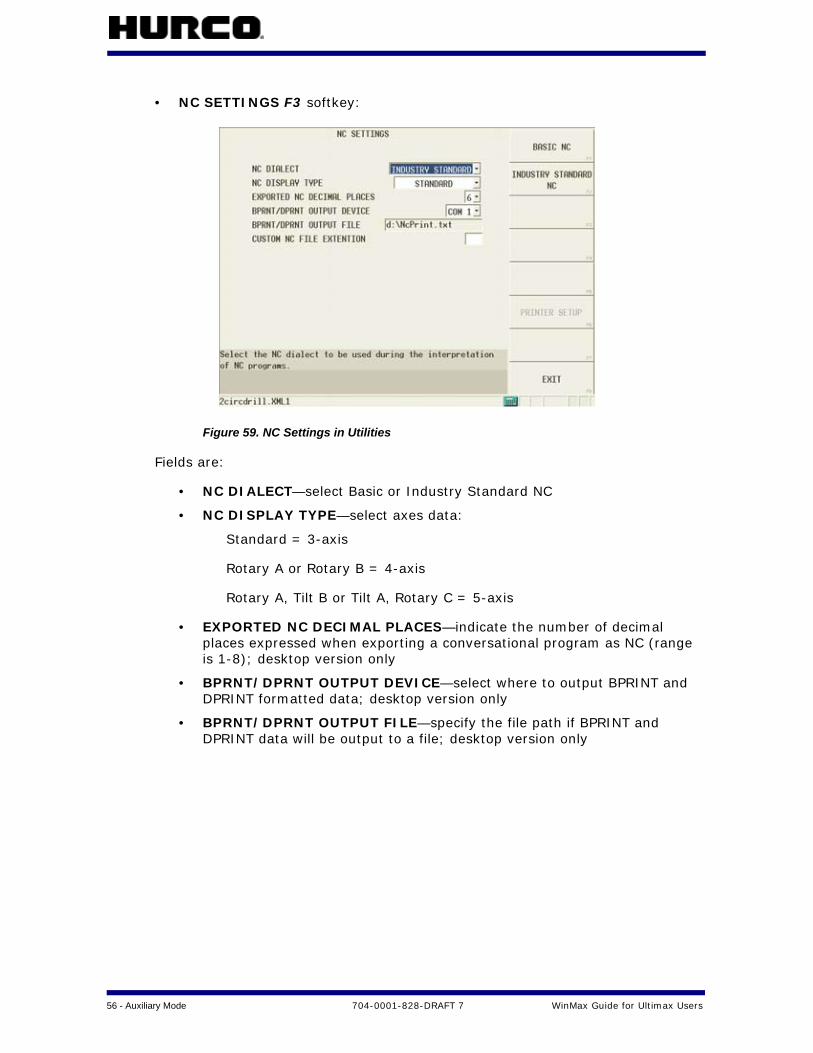
• NC SETTINGS F3 softkey:
Figure 59. NC Settings in Utilities
Fields are:
• NC DIALECT—select Basic or Industry Standard NC
• NC DISPLAY TYPE—select axes data:
Standard = 3-axis
Rotary A or Rotary B = 4-axis
Rotary A, Tilt B or Tilt A, Rotary C = 5-axis
• EXPORTED NC DECIMAL PLACES—indicate the number of decimal places expressed when exporting a conversational program as NC (range is 1-8); desktop version only
• BPRNT/DPRNT OUTPUT DEVICE—select where to output BPRINT and DPRINT formatted data; desktop version only
• BPRNT/DPRNT OUTPUT FILE—specify the file path if BPRINT and DPRINT data will be output to a file; desktop version only
WinMax Guide for Ultimax Users 704-0001-828-DRAFT 7 Auxiliary Mode — 57
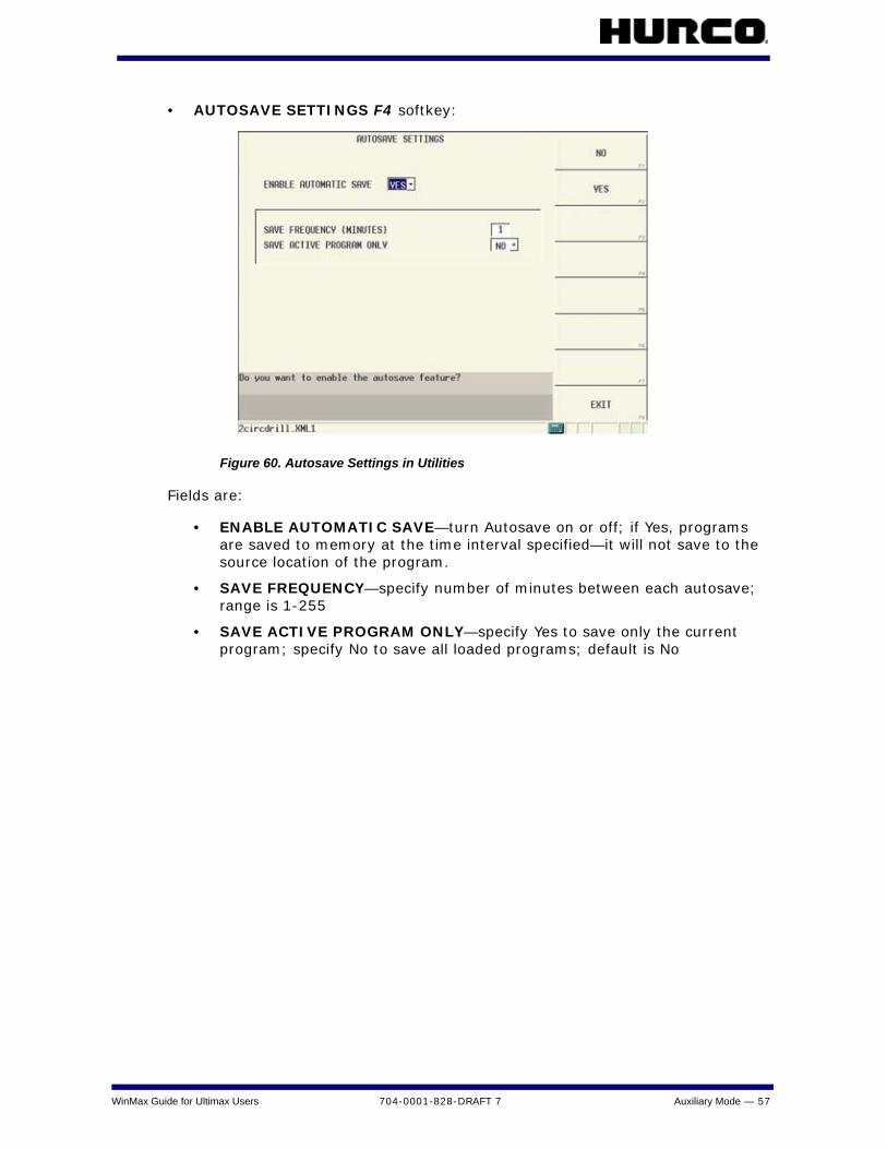
• AUTOSAVE SETTINGS F4 softkey:
Figure 60. Autosave Settings in Utilities
Fields are:
• ENABLE AUTOMATIC SAVE—turn Autosave on or off; if Yes, programs are saved to memory at the time interval specified—it will not save to the source location of the program.
• SAVE FREQUENCY—specify number of minutes between each autosave; range is 1-255
• SAVE ACTIVE PROGRAM ONLY—specify Yes to save only the current program; specify No to save all loaded programs; default is No

58 - Auxiliary Mode 704-0001-828-DRAFT 7 WinMax Guide for Ultimax Users
Other softkeys in the USER PREFERENCES screen are:
• SELECT LANGUAGE F5—select a language, if one has been installed, and touch the SELECT/LOAD softkey
Figure 61. User Preferences Screen 2 in Utilities (accessed with MORE softkey)
• SERIAL PORT SETTINGS F1—set Port 1 and Port 2 settings for protocol, baud rate, character length, stop bits, and parity
• FTP SERVER SETTINGS F2—set FTP settings (see the “Ultinet” section that follows for more information)
• WINMAX UPTIME F3—displays the start date time and runtime for the current session of Winmax
• TOOL UTILITIES AND SETTINGS F4—set tool utilities preferences; these settings vary depending on whether or not the Tool and Material Library option is enabled. See the “Tool Utilities and Settings” section for more information.
• MACHINE PARAMETERS F5—access the machine parameters
WinMax Guide for Ultimax Users 704-0001-828-DRAFT 7 Auxiliary Mode — 59
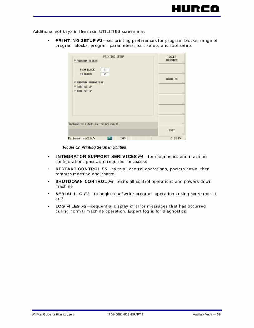
Additional softkeys in the main UTILITIES screen are:
• PRINTING SETUP F3—set printing preferences for program blocks, range of program blocks, program parameters, part setup, and tool setup:
Figure 62. Printing Setup in Utilities
• INTEGRATOR SUPPORT SERIVICES F4—for diagnostics and machine configuration; password required for access
• RESTART CONTROL F5—exits all control operations, powers down, then restarts machine and control
• SHUTDOWN CONTROL F6—exits all control operations and powers down machine
• SERIAL I/O F1—to begin read/write program operations using screenport 1 or 2
• LOG FILES F2—sequential display of error messages that has occurred during normal machine operation. Export log is for diagnostics.

60 - Auxiliary Mode 704-0001-828-DRAFT 7 WinMax Guide for Ultimax Users
UltiNetThe UltiNet option provides connection to your Local Area Network (LAN) for communication with other CNCs, PCs, or file servers using standard TCP/IP and FTP protocols.
UltiNet FTP ClientAny file operation performed by an operator at the machine uses the UltiNet FTP client:
1. From the Input screen, select the PROGRAM MANAGER F8 softkey.
2. From the Program Manager screen, select the FTP MANAGER F8 softkey.
3. Select host from the list and click the CONNECT F1 softkey, or select the ADD HOST F4 softkey to add a connection.
Figure 63. FTP Host List screen
The FTP Manager displays the current connection:
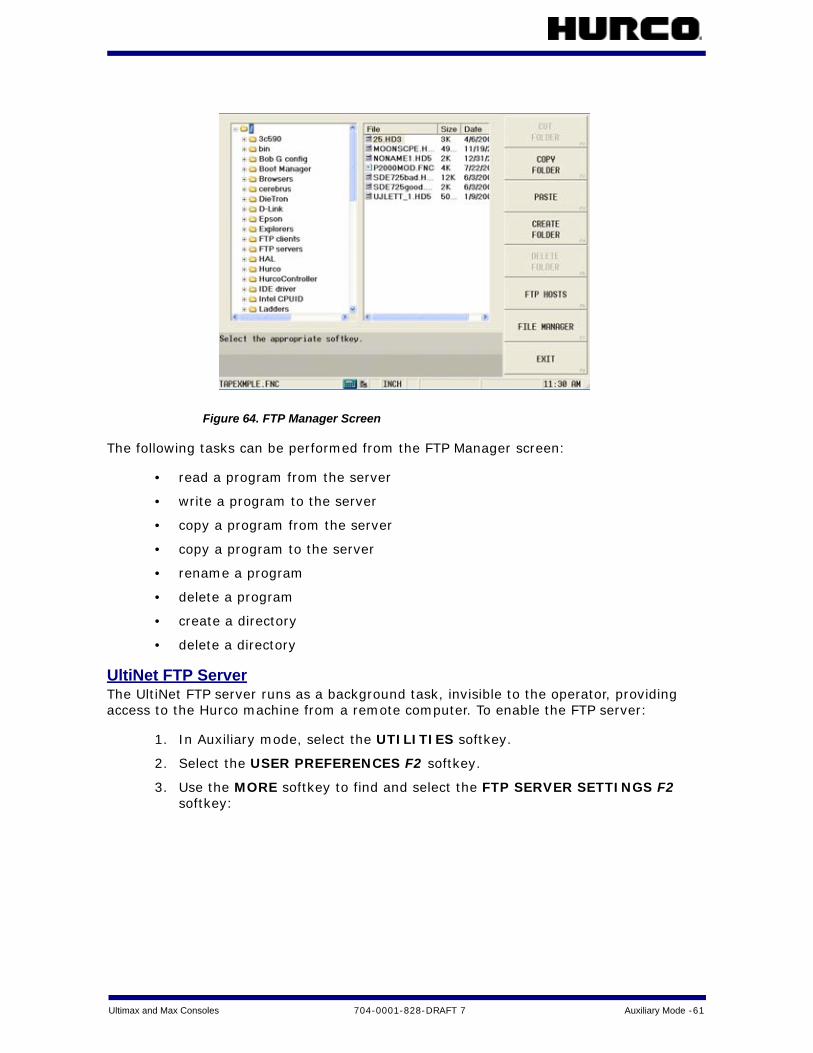
Ultimax and Max Consoles 704-0001-828-DRAFT 7 Auxiliary Mode -61
Figure 64. FTP Manager Screen
The following tasks can be performed from the FTP Manager screen:
• read a program from the server
• write a program to the server
• copy a program from the server
• copy a program to the server
• rename a program
• delete a program
• create a directory
• delete a directory
UltiNet FTP ServerThe UltiNet FTP server runs as a background task, invisible to the operator, providing access to the Hurco machine from a remote computer. To enable the FTP server:
1. In Auxiliary mode, select the UTILITIES softkey.
2. Select the USER PREFERENCES F2 softkey.
3. Use the MORE softkey to find and select the FTP SERVER SETTINGS F2 softkey:
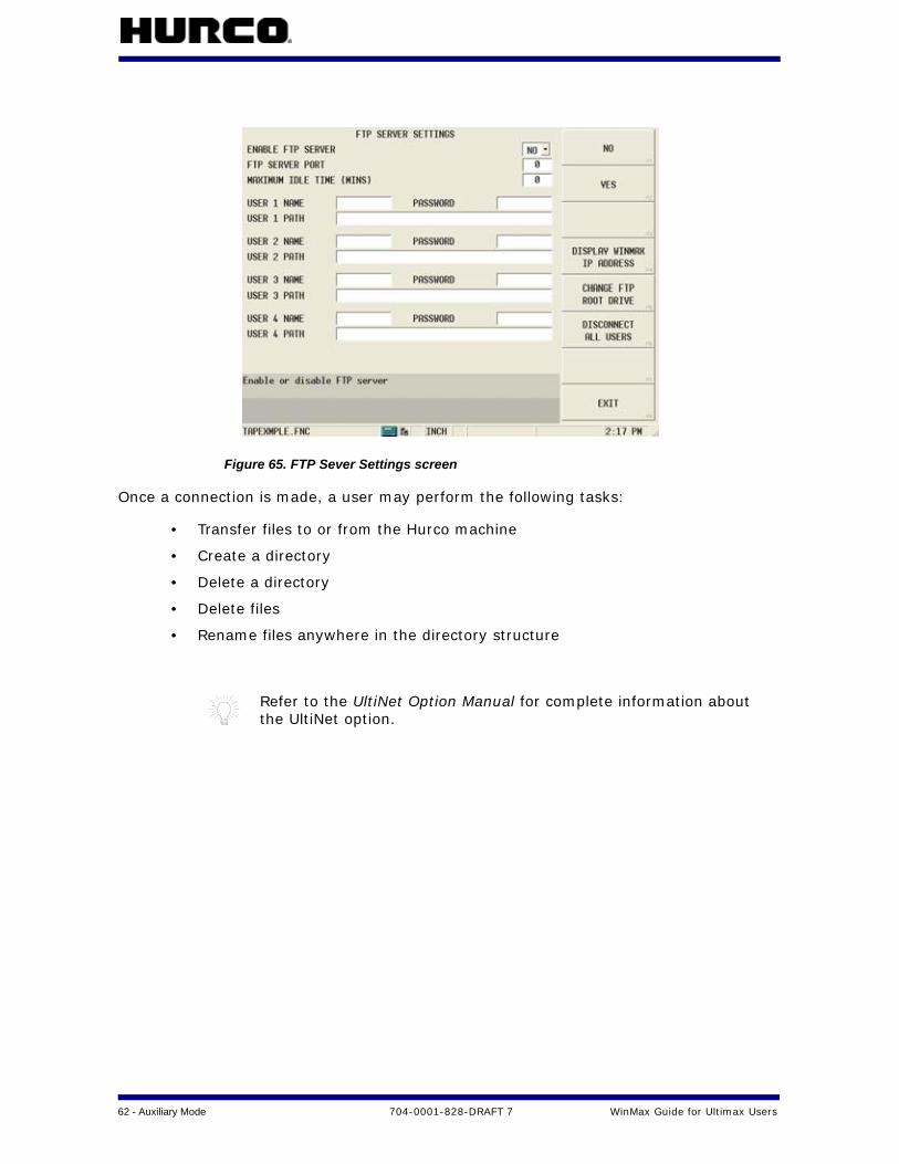
62 - Auxiliary Mode 704-0001-828-DRAFT 7 WinMax Guide for Ultimax Users
Figure 65. FTP Sever Settings screen
Once a connection is made, a user may perform the following tasks:
• Transfer files to or from the Hurco machine
• Create a directory
• Delete a directory
• Delete files
• Rename files anywhere in the directory structure
Refer to the UltiNet Option Manual for complete information about the UltiNet option.

Ultimax and Max Consoles 704-0001-828-DRAFT 7 Auxiliary Mode -63
Tool Utilities and SettingsThe Tool Utilities and Settings screen displays different fields with and without the Tool and Material Library option.
This screen shows Tool Utilities and Settings with the Tool & Material Library option:
Figure 66. Tool Utilities and Settings with Tool & Material Library option
Fields are:
• AUTOMATICALLY LOAD TOOLS INTO MTC—automatically load unmatched tools from existing conversational part programs into the MTC
• YES—new tools from loaded programs (that are not in Spindle, Auto, or Manual) are automatically added to Manual
• NO—requires tools to be matched (see “Part Program Tool Review” section for more information about matching tools.)
• USE TOOL TYPE CHECKING—only allow the selection of tool types that are valid for the operation in conversational mode
• YES—only the tools that are valid for the data block can be selected (i.e., drills and taps displayed for hole operations)
• NO—allows any tool to be selected for any data block
• OVERWRITE EXISTING ZERO CALIBRATION—when matching tools during a program load, the zero calibration from the program replaces the calibration for the tool on the machine. Default is YES.
• UPDATE DATA BLOCKS WITH TOOL CHANGES—update feeds and speeds in conversational data blocks when tool feeds and speeds are change
• REPLACE IN FILES—specify if new tool feeds and speeds should be updated in current editing file only or in all open files
• TOOL MATCHING: MAXIMUM DIAMETER DIFFERENCE—the maximum diameter difference for a tool to be considered a match

64 - Auxiliary Mode 704-0001-828-DRAFT 7 WinMax Guide for Ultimax Users
Softkeys are:
• TOOL INFORMATION PRINTING F6—allows the Tool Library to be printed or saved to a file
• IMPORT AND EXPORT F7—import and export tools to and from the Tool Library. To move the Tool Library from one machine to another, select EXPORT.
This screen shows Tool and Utilities Settings without the Tool & Material Library option:
Figure 67. Tool Utilities and Settings without Tool & Material Library option
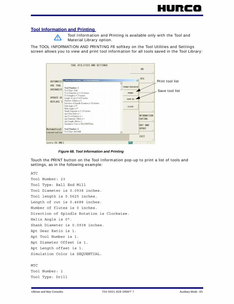
Ultimax and Max Consoles 704-0001-828-DRAFT 7 Auxiliary Mode -65
Tool Information and Printing
The TOOL INFORMATION AND PRINTING F6 softkey on the Tool Utilities and Settings screen allows you to view and print tool information for all tools saved in the Tool Library:
Figure 68. Tool Information and Printing
Touch the PRINT button on the Tool Information pop-up to print a list of tools and settings, as in the following example:
ATC
Tool Number: 23
Tool Type: Ball End Mill
Tool Diameter is 0.0938 inches.
Tool length is 0.5625 inches.
Length of cut is 0.4688 inches.
Number of flutes is 0 inches.
Direction of Spindle Rotation is Clockwise.
Helix Angle is 0°.
Shank Diameter is 0.0938 inches.
Apt Gear Ratio is 1.
Apt Tool Number is 1.
Apt Diameter Offset is 1.
Apt Length offset is 1.
Simulation Color is SEQUENTIAL.
MTC
Tool Number: 1
Tool Type: Drill
Tool Information and Printing is available only with the Tool and Material Library option.
Print tool list
Save tool list

66 - Auxiliary Mode 704-0001-828-DRAFT 7 WinMax Guide for Ultimax Users
Tool Diameter is 0.031 inches.
Tool length is 5 inches.
Length of cut is 5 inches.
Number of flutes is 0 inches.
Direction of Spindle Rotation is Clockwise.
Drill Angle is 118.000000°.
Helix Angle is 0°.
Shank Diameter is 0.031 inches.
Apt Gear Ratio is 1.
Apt Tool Number is 1.
Apt Diameter Offset is 1.
Apt Length offset is 1.
Simulation Color is SEQUENTIAL.
Tool Number: 20
Tool Type: Cutting Tap
Tool Diameter is 0.216 inches.
Tool length is 1.296 inches.
Length of cut is 1.08 inches.
Tap Direction: Right Hand.
Tap Chamfer: Bottoming.
Thread Pitch is 0.0417 inches.
Thread Diameter is 0.216 inches.
Helix Angle is 0°.
Flute Style: Spiral Flute.
Shank Diameter is 0.216 inches.
Apt Gear Ratio is 1.
Apt Tool Number is 1.
Apt Diameter Offset is 1.
Apt Length offset is 1.
Simulation Color is SEQUENTIAL.

Ultimax and Max Consoles 704-0001-828-DRAFT 7 Auxiliary Mode -67
Import and Export
The IMPORT AND EXPORT F7 softkey in Tool Utilities and Settings allows you to move tool information from the WinMax control to other locations and vice versa.
Figure 69. Import and Export Softkeys
Import and Export submenu softkeys are:
• EXPORT AUTO AND MANUAL TOOLS F1—save Auto and Manual tools to a different directory
• EXPORT MANUAL TOOLS F2—save Manual tools only to a different directory
• IMPORT MANUAL TOOLS F3—load Manual tools into the control from a directory
Import and Export functions are available only with the Tool and Material Library option.

68 - Auto Mode 704-0001-828-DRAFT 7 WinMax Guide for Ultimax Users
AUTO MODEPrograms are run in Auto Mode. Press the Auto button on the console to access Auto Mode to check for errors, compute estimated run time, recovery/restart, perform a dry run, or run a part program.
The USE EDITING FILE F1 softkey is new in WinMax. It is used to select the active program file to run the part. If this softkey is not selected, WinMax defaults to the last program run. If the last program run does not match the program that is being edited (as indicated in status bar), the operator will be prompted to select which program to run.
Figure 70. Auto Screen (NC)
The Run Program screen shows the status of the part program being run. For NC programs, five lines of NC code are shown on this screen. To view more NC code as the program runs, select the NC MONITOR F6 softkey.
Run partprogram
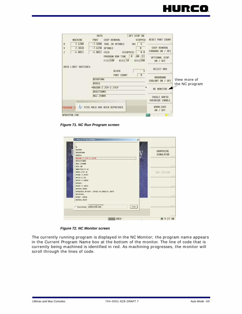
Ultimax and Max Consoles 704-0001-828-DRAFT 7 Auto Mode -69
Figure 71. NC Run Program screen
Figure 72. NC Monitor screen
The currently running program is displayed in the NC Monitor; the program name appears in the Current Program Name box at the bottom of the monitor. The line of code that is currently being machined is identified in red. As machining progresses, the monitor will scroll through the lines of code.
View more ofthe NC program
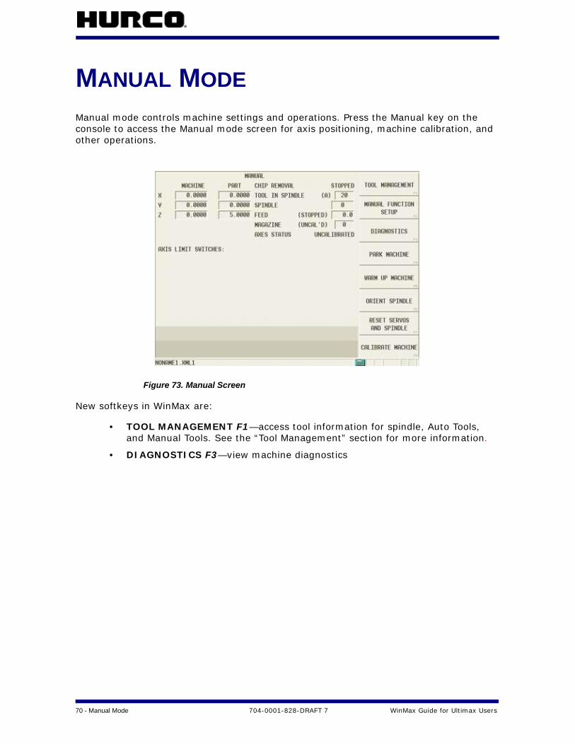
70 - Manual Mode 704-0001-828-DRAFT 7 WinMax Guide for Ultimax Users
MANUAL MODEManual mode controls machine settings and operations. Press the Manual key on the console to access the Manual mode screen for axis positioning, machine calibration, and other operations.
Figure 73. Manual Screen
New softkeys in WinMax are:
• TOOL MANAGEMENT F1—access tool information for spindle, Auto Tools, and Manual Tools. See the “Tool Management” section for more information.
• DIAGNOSTICS F3—view machine diagnostics

Ultimax and Max Consoles 704-0001-828-DRAFT 7 Graphics -71
GRAPHICSWinMax graphics include Toolpath (similar to Ultimax) and new Solid graphics. Real-time graphic animation is available with the new Runtime tool, which shows a simulated tool cutting the part on screen while the machine is cutting the actual part.
Graphics preferences are set in the Graphics Settings screen, which is accessed with the GRAPHICS SETTINGS F8 softkey:
Figure 74. Graphics Settings
Fields on the Graphics Settings screen are:
• DEFAULT VIEW—set the default view when WinMax is started, either XY plane, XZ plane, Isometric, or All Views.
• SHOW GRAPHICS—set the type, either Show All, Toolpath, or Solids
• TOOL PATH—specify Yes or No to show the tool path (appears as red dashed line)
• PART SURFACE—specify Yes or No to show the part surface (appears as solid cyan line)
• RAPIDS—specify Yes or No to show rapid moves (appears as yellow solid lines)
• STOCK OUTLINE—specify Yes or No to show the stock outline, which is set in the stock geometry screen (appears as green solid line). Refer to the “Stock Geometry” section in Part Setup for more information.
• PLUNGES—specify Yes or No to show plunge moves (appears as purple lines)
Tool Pat and Solid graphics, and Runtime tool are only available with the Advanced Verification Graphics option.

72 - Graphics 704-0001-828-DRAFT 7 WinMax Guide for Ultimax Users
• SHOW PECKS OF CONTOURS—specify Yes or No to show all the roughing tool path, applies only to Toolpath graphics
• SHOW PECKS OF 3D SURFACES—specify Yes or No to show all the pecks during milling of 3D mold and swept surface blocks
• SHOW RUNTIME TOOL—specify Yes or No to see simulated tool move around the part while the machine is running; tool also shown when jogging tool near part
• SHOW SFQ—specify Yes or No to show surface quality indicator while the machine is running; only in Auto mode (appears as horizontal bar)
• SHOW F-ERROR—specify Yes or No to show following error (difference between commanded position and actual position) while machine is running; only in Auto mode
• USE CHORD ERROR FROM PROGRAM?—specify Yes or No to use the chord error value programmed in general parameters when rendering curves in NC
• GRAPHICS CHORD ERROR—enter the chord error to be used when drawing curves in graphics
• BACKGROUND COLOR—choose Black or White background color
• SCREEN REFRESH RATE—choose how often the screen refreshes when displaying the runtime tool, based on machining feedrate:
• EVERY 20 SECONDS
• EVERY 10 SECONDS
• EVERY 5 SECONDS
• ONCE PER SECOND
• 5 TIMES PER SEONDS
• 10 TIMES PER SECOND
• 20 TIMES PER SECOND
The faster refresh rate will represent more uniform motion but will consume more system memory and processing speed.

Ultimax and Max Consoles 704-0001-828-DRAFT 7 Graphics -73
Toolpath GraphicsToolpath graphics displays a wireframe view of the part. Toolpath may also be animated to show the tool in motion if the runtime tool is displayed.
Figure 75. Toolpath graphic display
Solid GraphicsSolid graphics displays a solid 3-dimensional part.
Figure 76. Solid graphic display
Denotes theview selected
Indicatesthe stage ofprocessing

74 - Graphics 704-0001-828-DRAFT 7 WinMax Guide for Ultimax Users
The console Draw button initiates drawing. The Draw Options menu is displayed (for both Toolpath and Solid) to control drawing and animation:
• DRAW OPTIONS F1—displays the following draw options:
• DRAW (PAUSE) F1—starts drawing the part. When drawing is in progress, the softkey displays PAUSE—select it to pause the drawing. When paused, the softkey displays DRAW—select it to resume drawing.
• ACCLERATED DRAW F2—displays the completed part without showing each block as it is being drawn
• SINGLE STEP F3—displays only one step or program block at a time. Subsequent selection of SINGLE STEP will execute the next step or block.
• NEXT TOOL CHANGE F4—displays cutting from one tool change to the next
• SELECT VIEW F2—choose XY plane, XZ plane, YZ plane, Isometric, or All Views
• ZOOM F3—magnifies an area of the graphic. Select the softkey and choose one of the following:
• ZOOM IN F1—magnify incrementally by 20% each time the softkey is selected
• ZOOM OUT F2—shrink view incrementally by 10% each time the softkey is selected
• FIT TO VIEW F3—returns drawing to full view
• “Touch-and-drag”—place stylus at a point on the screen and drag it to expand the box over the area you wish to magnify. When stylus is lifted from screen the area will be magnified.
• PAN F4—moves the graphic up, down, left, or right. Use the softkeys or touch the screen and drag the graphic.
• ROTATE F5—changes the rotation of the graphic
• DB SEARCH F6—jumps to a selected data block. Select the softkey, touch an area on the graphic touchscreen, and select the JUMP TO BLOCK softkey.
• SNAPSHOT F7—creates an image of the solid that is stored with the XML1 file. The image is displayed on the Program Manager screen when the program is highlighted.
• GRAPHICS SETTINGS F8—displays the Graphics Settings screen
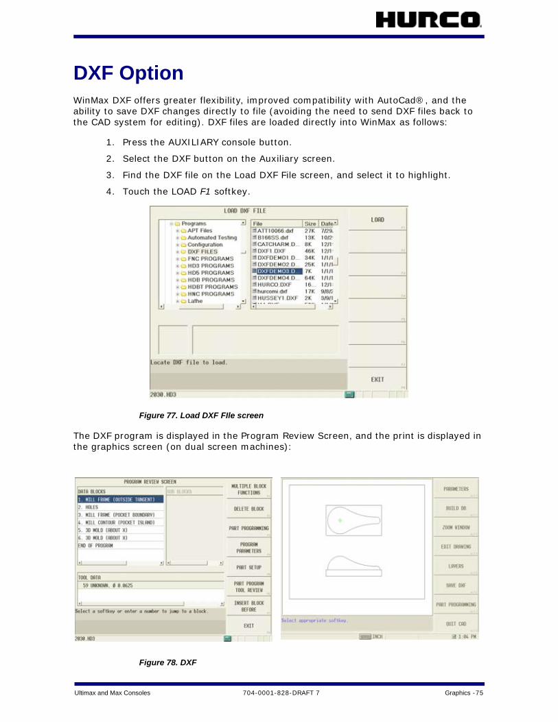
Ultimax and Max Consoles 704-0001-828-DRAFT 7 Graphics -75
DXF OptionWinMax DXF offers greater flexibility, improved compatibility with AutoCad®, and the ability to save DXF changes directly to file (avoiding the need to send DXF files back to the CAD system for editing). DXF files are loaded directly into WinMax as follows:
1. Press the AUXILIARY console button.
2. Select the DXF button on the Auxiliary screen.
3. Find the DXF file on the Load DXF File screen, and select it to highlight.
4. Touch the LOAD F1 softkey.
Figure 77. Load DXF FIle screen
The DXF program is displayed in the Program Review Screen, and the print is displayed in the graphics screen (on dual screen machines):
Figure 78. DXF
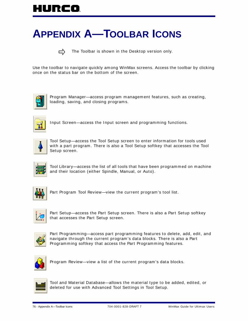
76 - Appendix A—Toolbar Icons 704-0001-828-DRAFT 7 WinMax Guide for Ultimax Users
APPENDIX A—TOOLBAR ICONS
Use the toolbar to navigate quickly among WinMax screens. Access the toolbar by clicking once on the status bar on the bottom of the screen.
The Toolbar is shown in the Desktop version only.
Program Manager—access program management features, such as creating, loading, saving, and closing programs.
Input Screen—access the Input screen and programming functions.
Tool Setup—access the Tool Setup screen to enter information for tools used with a part program. There is also a Tool Setup softkey that accesses the Tool Setup screen.
Tool Library—access the list of all tools that have been programmed on machine and their location (either Spindle, Manual, or Auto).
Part Program Tool Review—view the current program's tool list.
Part Setup—access the Part Setup screen. There is also a Part Setup softkey that accesses the Part Setup screen.
Part Programming—access part programming features to delete, add, edit, and navigate through the current program's data blocks. There is also a Part Programming softkey that access the Part Programming features.
Program Review—view a list of the current program's data blocks.
Tool and Material Database—allows the material type to be added, edited, or deleted for use with Advanced Tool Settings in Tool Setup.

Ultimax and Max Consoles 704-0001-828-DRAFT 7 Appendix A—Toolbar Icons -77
Graphics—display the part in Toolpath or Solid graphics.
DXF Editor—access the DXF editor functions.
Utility Screen—access Machine Specifications, User Preferences, Printing, Post Processor, Language Selection, and Log functions.
Help—access context-sensitive Help screens. Place the cursor on a field and click on the Help button to get information about the field.
To move the toolbar to another location on the screen, grab it with the pointer and drag it to the new place. To return the toolbar to its previous location, close it (select the X in the screen's upper right-hand corner), then select any point in the status bar. The toolbar reappears in its previous position.
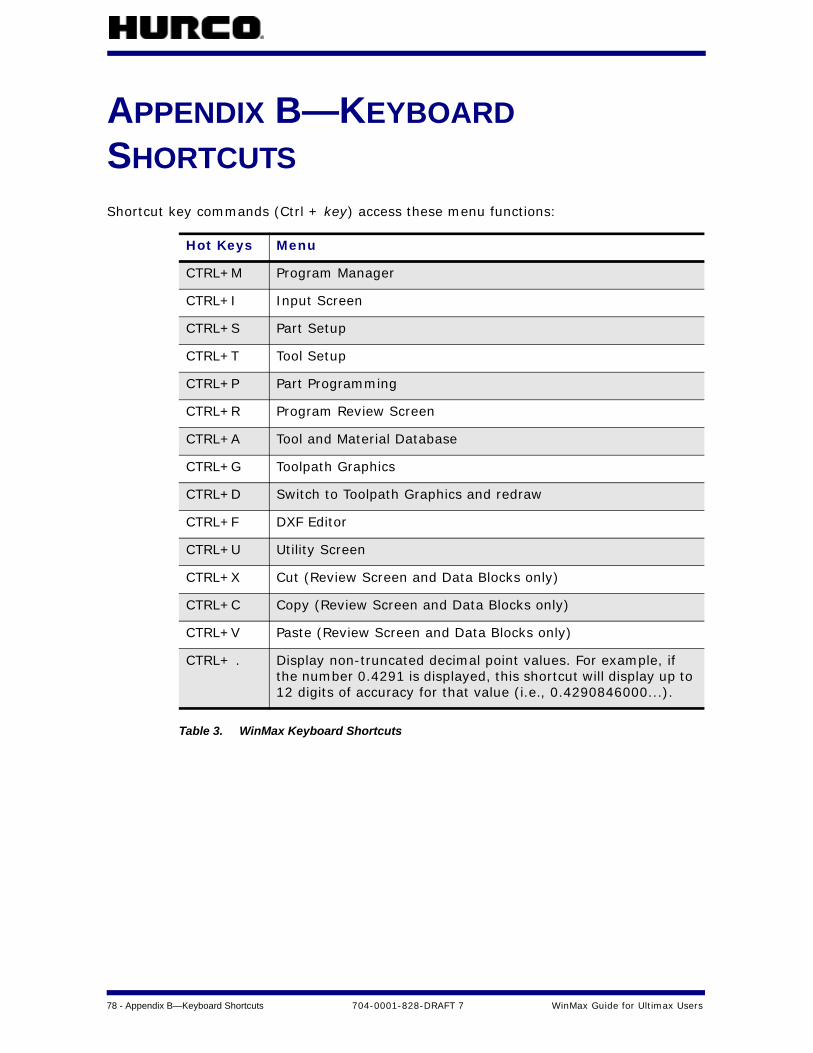
78 - Appendix B—Keyboard Shortcuts 704-0001-828-DRAFT 7 WinMax Guide for Ultimax Users
APPENDIX B—KEYBOARD SHORTCUTSShortcut key commands (Ctrl + key) access these menu functions:
Table 3. WinMax Keyboard Shortcuts
Hot Keys Menu
CTRL+M Program Manager
CTRL+I Input Screen
CTRL+S Part Setup
CTRL+T Tool Setup
CTRL+P Part Programming
CTRL+R Program Review Screen
CTRL+A Tool and Material Database
CTRL+G Toolpath Graphics
CTRL+D Switch to Toolpath Graphics and redraw
CTRL+F DXF Editor
CTRL+U Utility Screen
CTRL+X Cut (Review Screen and Data Blocks only)
CTRL+C Copy (Review Screen and Data Blocks only)
CTRL+V Paste (Review Screen and Data Blocks only)
CTRL+ . Display non-truncated decimal point values. For example, if the number 0.4291 is displayed, this shortcut will display up to 12 digits of accuracy for that value (i.e., 0.4290846000...).
WinMax Guide for Ultimax Users 704-0001-828-DRAFT 7 Index — 1
INDEX
Numerics3-D Mold (Swept Surface) 22
AACCLERATED DRAW F2 softkey, graphics
screen 74ADD AS MANUAL TOOL F5 softkey, Un-
matched Tools Review 49ADD MATERIAL F1 softkey, Tool and Mate-
rial Database screen 45ADD TOOL F1 softkey, Tool and Material
Database 44ADD TOOL F1 softkey, Tool and Material
Database screen 44Advanced Tool Settings 38ADVANCED TOOL SETTINGS F1 softkey,
Tool Setup screen 10Angle field, Advanced Tool Settings 39APPLICATION FONT SIZE, User Interface
Settings 54Auto Mode 68AUTOMATIC TOOL MONITORING field,
Probing Parameters 23AUTOMATICALLY LOAD TOOLS INTO MTC,
Tool Utilities and Settings 63AUTOMATICALLY LOAD UNMATCHED
TOOLS AS MANUAL field 49AUTOSAVE SETTINGS F4 softkey, Utilities
screen 57Auxiliary Mode 51
BBACKGROUND COLOR field, Graphics Set-
tings 72BORDER SIZE
Stock Geometry screen 9BPRNT/DPRNT OUTPUT DEVICE, NC Set-
tings 56BPRNT/DPRNT OUTPUT FILE, NC Settings
56
CCalculator 5calculator 4Chamfer Angle field, Advanced Tool Set-
tings 39CHANGE TOOL NUMBER F2 softkey, Tool
Setup screen 10CHANGE TOOL NUMBER F5 softkey, Tool Li-
brary screen 37CHIPLOAD field, Advanced Tool Settings 40CLEAR TOOLS F6 softkey, Tool Library
screen 37COLOR field, Advanced Tool Settings 38Comment Block 19console keys 2Constant Z level, in Swept Surface 22CONTOUR COUNT
True-Type Lettering 18CONVERSATIONAL PROGRAM F1 softkey,
Program Manager 29CONVERSATIONAL SETTINGS F2, Utilities
screen 55CONVERT TO LINEAR F7 softkey, Program
Review screen 47CONVERT TO ROTARY F6 softkey, Program
Review screen 47COOLANT field, Advanced Tool Settings 40COPY AND CHANGE BLOCKS F6
Input Screen 7COPY DIRECTORY F2 softkey
Disk Operations 33COPY F2 softkey
Disk Operations 34COPY F2 softkey, Program Review screen
46CREATE DIRECTORY F4 softkey
Disk Operations 33Cusp Height, In Swept Surface 22CUT DIRECTORY F1 softkey
Disk Operations 33CUT F1 softkey
Disk Operations 34CUT F1 softkey, Program Review screen 46Cutting Edges field, Advanced Tool Settings
39CUTTING TIME field, Tool Setup screen 10
DDB SEARCH F6 softkey, graphics screen 74DEFAULT VIEW field, Graphics Settings 71DEFAULT XML PROGRAM TYPE, Conversa-
tional Settings 55DELETE DIRECTORY F6 softkey
Disk Operations 33DELETE F4 softkey, Program Review screen
46DELETE F5 softkey
Disk Operations 34DELETE MATERIAL F3 softkey, Tool and Ma-
terial Database screen 45
2 - Index 704-0001-828-DRAFT 7 WinMax Guide for Ultimax Users
DESCRIPTION field, in Program Properties 32
DIAGNOSTICS F3 softkey, Manual screen 70
Diameter field, Advanced Tool Settings 39DIAMETER TOLERANCE field, Probing Pa-
rameters 23DIRECTION field, Advanced Tool Settings
38Disk Operations 33DISK OPERATIONS F7 softkey, Program
Manager 31DISPLAY UNITS field, in Program Properties
32DRAW (PAUSE) F1 softkey, graphics screen
74DRAW OPTIONS F1 softkey, graphics
screen 74Drill Angle field, Advanced Tool Settings 39drop-down lists 2DXF Editor icon 77DXF Option 75
EEDIT MATERIAL F2 softkey, Tool and Mate-
rial Database screen 45EDIT MODE, User Interface Settings 54EDIT TOOL F2 softkey, Tool and Material
Database screen 44ENABLE AUTOMATIC SAVE, Autosave Set-
tings 57ENABLE PROJECT RESTORE, User Interface
Settings 54Enable Tool SFQ field, Advanced Tool Set-
tings 41ERASE FUCNTIONS F7
Input Screen 7Erase Functions 28ERASE PART SETUP F1 28ERASE PROGRAM F4 28ERASE TOOL SETUP F2 28Expand and Collapse Files 3EXPORT AUTO AND MANUAL TOOLS F1,
Import and Export 67EXPORT MANUAL TOOLS F2, Import and
Export 67EXPORTED NC DECIMAL PLACES, NC Set-
tings 56
FFeed and Speed, Advanced Tool Settings
40FEED field, Advanced Tool Settings 40
FIT TO VIEW F3 softkey, graphics screen 74Flutes field, Advanced Tool Settings 39FONT
True-Type Lettering 18FTP MANAGER F7 softkey
Disk Operations 33, 34FTP MANAGER F8 softkey, Program Manag-
er 31FTP SERVER SETTINGS F2 softkey, Utilities
screen 58
GG5.3P 41G-code, NC/Conversational Merge 20Geometry, Advanced Tool Settings 38Graphics 71GRAPHICS CHORD ERROR field, Graphics
Settings 72Graphics icon 77GRAPHICS SETTINGS F8 71GRAPHICS SETTINGS F8 softkey, graphics
screen 74Graphics Settings, for Stock Geomety 8
HHD3 SAVE PROGRAM TYPE, Conversational
Settings 55Help
in Pattern Blocks 19Help icon 77
IImport and Export 67IMPORT AND EXPORT F7 softkey, Tool Util-
ities and Settings 64Import Fucntions
PART SETUP 27Import Functions 27
PART PROGRAM 27PROGRAM PARAMETERS 27TOOL SETUP 27
IMPORT FUNCTIONS F5 7IMPORT MANUAL TOOLS F3, Import and
Export 67Input Mode 7Input Screen icon 76INSERT SEGMENT BEFORE
Mill Contour screen 17INSERT TOOL F3 softkey, Tool Library
screen 37INTEGRATOR SUPPORT SERIVICES F4 soft-
key, Utilities screen 59

WinMax Guide for Ultimax Users 704-0001-828-DRAFT 7 Index — 3
interface 2ISNC, in NC/Conversationl Merge 20
Kkeyboard 2, 4keyboard shortcuts 78
LLength of Cut field, Advanced Tool Settings
39Lettering
HD3 17True-Type 17
LIST CONTROL ROWS, User Interface Set-tings 54
LIST ICON SIZE, User Interface Settings 54LOAD F6 softkey
Disk Operations 34LOG FILES F2 softkey, Utilities screen 59
MMACHINE PARAMETERS F4 softkey, Utilities
screen 58MANUAL BORDER SIZING
Stock Geometry screen 9Manual Mode 70
Tool Library 35MANUAL STOCK SIZING
Stock Geometry screen 9MATCH TOOLS F4 softkey, Unmatched
Tools Review 49Matching tools 49MATERIAL field, in Program Properties 32MATH ASSIST STYLE, Conversational Set-
tings 55MAX DEPTH field, Advanced Tool Settings
40Mill Contours 17Milling Blocks 16Miscellaneous Block 19MOVE TOOL TO SPINDLE F1 softkey, Tool
Library screen 36, 37MULTIPLE BLOCK FUNCTIONS F2 softkey,
Program Review screen 46
NNAME field, in Program Properties 32NC DIALECT, NC Settings 56NC DISPLAY TYPE, NC Settings 56NC MONITOR F6 softkey, NC/Conversation-
al Merge 68NC PROGRAM F2 softkey, Program Manager
30NC SETTINGS F3 softkey, Utilities screen 56NC SFQ, Advanced Tool Settings 41NC/Conversational Merge 20Neck Diameter field, Advanced Tool Set-
tings 39NEW F1 softkey, Program Manager 29NEXT SEGMENT F2
Mill Contour screen 17NEXT TOOL CHANGE F4 softkey, graphics
screen 74NEXT TOOL field, Tool Library screen 35Notes, Advanced Tool Settings 43
OOnline Help 5ORIENTATION
True-Type Lettering 18
PPAN F4 softkey, graphics screen 74Part Program Tool Review
Review,Tools in Part Program 48PART PROGRAM TOOL REVIEW F5 softkey,
Tool Setup screen 10Part Program Tool Review icon 76Part Programming 10
Position Block 15PART PROGRAMMING F3
Input Screen 7Part Programming icon 76Part Setup 8PART SETUP F1
Input Screen 7Part Setup icon 76Part Setup, STOCK GEOMETRY 8PART SURFACE field, Graphics Settings 71PASTE F3 softkey
Disk Operations 34PASTE F3 softkey, Program Review screen
46PASTE INTO DIRECTORY F3 softkey
Disk Operations 33PATH field, in Program Properties 32Pattern Block 19PECK DEPTH field, Advanced Tool Settings
40PLUNGE FEED field, Advanced Tool Settings
40PLUNGES field, Graphics Settings 71pop-ups 3Position Block 15PREVIOUS SEGMENT F1
4 - Index 704-0001-828-DRAFT 7 WinMax Guide for Ultimax Users
Mill Contour screen 17PRINTING SETUP F3 softkey, in Utilities
screen 59Program Manager 29Program Manager icon 76Program Parameters 23PROGRAM PARAMETERS F4
Input Screen 7Program Properties 32PROGRAM PROPERTIES F6 softkey, Pro-
gram Manager 31Program Review icon 76Program Review screen 46PROGRAM TYPE, in Program Properties 32PROJECT MANAGER F8
Input Screen 7
RRADIAL WEAR field, Tool Setup screen 10Radius field, Advanced Tool Settings 39RAPIDS field, Graphics Settings 71Ream Chamfer field, Advanced Tool Set-
tings 39REMOVE TOOL F3 softkey, Tool and Materi-
al Database screen 44RENAME DIRECTORY F5 softkey
Disk Operations 33RENAME F4 softkey
Disk Operations 34RESET PROGRAM PARAMETERS F3 28RESTART CONTROL F5 softkey, Utilities
screen 59RESTORE USER DEFAULTS F5 softkey, Pro-
gram Parameters 23RESTORE WINMAX DEFAULTS F6 softkey,
Program Parameters 23Review Mode 46ROTATE F5 softkey, graphics screen 74
SSAVE ACTIVE PROGRAM ONLY, Autosave
Settings 57SAVE AS USER DEFAULTS F4 softkey, Pro-
gram Parameters 23SAVE FREQUENCY, Autosave Settings 57SCREEN REFRESH RATE field, Graphics
Settings 72SCREENSAVER TIMEOUT, User Interface
Settings 54SELECT LANGUAGE F5 softkey, Utilities
screen 58SELECT MATERIAL FOR PART PROGRAM F5
softkey, Tool and Material Database
screen 45Select Surface 24Select Tool from List 14SELECT VIEW F2 softkey, graphics screen
74SelectSurface Finish Quality 23, 24, 25SERIAL I/O F1 softkey, Utilities screen 59SERIAL PORT SETTINGS F1 softkey, Utili-
ties screen 58SFQ 24
Change Parameters Block 25changing in Individual Tool in NC 26changing in Program Parameters 24G5.3P NC Command 26Global Program Parameters 26in Conversational Programming 24in Individual Data Blocks 25in NC Programming 26Milling Blocks 16
Shank Diameter field, Advanced Tool Set-tings 39
SHOW ALL FILE TYPES, User Interface Set-tings 54
SHOW F-ERROR field, Graphics Settings 72SHOW GRAPHICS field, Graphics Settings
71SHOW PECKS OF 3D SURFACES field,
Graphics Settings 72SHOW PECKS OF CONTOURS field, Graph-
ics Settings 72SHOW RUNTIME TOOL field, Graphics Set-
tings 72SHOW SFQ field, Graphics Settings 72SHUTDOWN CONTROL F6 softkey, Utilities
screen 59SINGLE STEP F3 softkey, graphics screen
74SNAPSHOT F7 softkey, graphics screen 74SOFTKEY MENU POSITION, User Interface
Settings 54softkeys 2Solid Graphics 73SPEED field, Advanced Tool Settings 40Spiral, in Swept Surface 22Status Bar 4Stock Geometry 8STOCK GEOMETRY F1
Part Setup 8Stock Geometry screen 9STOCK OUTLINE field, Graphics Settings 71STOCK OUTLINE, Graphics Settings 8STOCK TYPE
Stock Geometry screen 9Stylus Length field, Advanced Tool Settings
39

WinMax Guide for Ultimax Users 704-0001-828-DRAFT 7 Index — 5
Supplier, Advanced Tool Settings 42Surface Finish Quality 24SURFACE SPEED field, Advanced Tool Set-
tings 40Swept Surface 22SYSTEM CONFIGURATION F1 softkey, Utili-
ties screen 52
TTabs
Milling Block 16SFQ 16
Taps 12TEXT
True-Type Lettering 18Thread Diameter field, Advanced Tool Set-
tings 39Threads per inch field, Advanced Tool Set-
tings 39time 4Tip Angle field, Advanced Tool Settings 39Tip Diameter field, Advanced Tool Settings
39Tip Length field, Advanced Tool Settings 39Tool and Material Database 44Tool and Material Database icon 76TOOL IN SPINDLE field, Tool Library screen
35Tool Information and Printing 65TOOL INFORMATION PRINTING F6 softkey,
Tool Utilities and Settings 64Tool Length field, Advanced Tool Settings
39Tool Library 35
Auto 35, 36Manual 35, 37Spindle 35
TOOL LIBRARY F1 softkey, Manual screen 70
Tool Library icon 76Tool Matching 49Tool Matching Results 49Tool Number 13TOOL PATH field, Graphics Settings 71TOOL REVIEW F2
Input Screen 7Tool Selection 13Tool Settings and Utilities 49Tool Setup 38TOOL SETUP F1 softkey, Unmatched Tools
Review 49TOOL SETUP F4 softkey, Tool Library screen
37Tool Setup icon 76
Tool Type Checking 15Tool Type Setup/Advanced Tool Settings 44TOOL UTILITIES AND SETTINGS F4 soft-
key, Utilities screen 58Toolbar Icons 76Toolpath Graphics 73touchscreen 2True-Type Lettering 17
UUltimax classic edit mode 2unit of measure 4UNLOAD PROGRAM F5 28USE CHORD ERROR FROM PROGRAM? field,
Graphics Settings 72USE EDITING FILE F1 softkey, Auto screen
68USE TOOL TYPE CHECKING, Tool Utilities
and Settings 63USER INTERFACE SETTTINGS F1 softkey,
Utilities screen 54USER PREFERENCES F2 softkey, Utilities
screen 53Utilities 52Utility Screen icon 77
WWARN BEFORE SAVING IN OLD FORMAT,
User Interface Settings 54WinMax Interface Environment 2WINMAX UPTIME F3 softkey, Utilities
screen 58WRITE PROTECTION field, in Program Prop-
erties 32
XX BASE
True-Type Lettering 18X LENGTH
True-Type Lettering 18X REF POSITION
Stock Geometry screen 9
YY BASE
True-Type Lettering 18Y LENGTH
True-Type Lettering 18Y MAPPING
True-Type Lettering 18Y REF POSITION
Stock Geometry screen 9
6 - Index 704-0001-828-DRAFT 7 WinMax Guide for Ultimax Users
ZZ BOTTOM
True-Type Lettering 18Z REF POSITION
Stock Geometry screen 9Z START
True-Type Lettering 18ZERO CAL (LENGTH) TOLERANCE field,
Probing Parameters 23ZERO REF
Stock Geometry screen 9ZOOM F3 softkey, graphics screen 74ZOOM IN F1 softkey, graphics screen 74ZOOM OUT F2 softkey, graphics screen 74