
WiNG 5.X How-To Guide - Michael McNamara – …€¦ · · 2013-11-07WiNG 5.X How-To Guide –...
80
WiNG 5.X How-To Guide Auto IPsec Secure using Pre Shared Keys Part No. TME-09-2012-01 Rev. A
Transcript of WiNG 5.X How-To Guide - Michael McNamara – …€¦ · · 2013-11-07WiNG 5.X How-To Guide –...

WiNG 5.X How-To Guide
Auto IPsec Secure using Pre Shared Keys
Part No. TME-09-2012-01 Rev. A

MOTOROLA, MOTO, MOTOROLA SOLUTIONS and the Stylized M Logo are trademarks or registered trademarks of Motorola Trademark Holdings, LLC and are used under license. All other trademarks are
the property of their respective owners.
© 2012 Motorola Solutions, Inc. All Rights Reserved.

Table of Contents
Table of Contents ............................................................................................................................ 3
1. Overview .................................................................................................................................. 4
1.1 Implementation ................................................................................................................. 5
1.2 Platform Support .............................................................................................................. 7
2. Configuration Examples .......................................................................................................... 8
2.1 Private Network Deployments.......................................................................................... 8
2.2 Public Network Deployments with NAT/Firewalls.......................................................... 20
2.3 Public Network Deployments with VPN Gateways........................................................ 36
3. Verification ............................................................................................................................. 52
3.1 Adoption Status .............................................................................................................. 52
3.2 MINT Links ..................................................................................................................... 53
3.3 IKEv2 Security Association ............................................................................................ 53
3.4 IPsec Security Associations ........................................................................................... 54
4. Appendix ................................................................................................................................ 56
4.1 Running Configurations.................................................................................................. 56

WiNG 5.X How-To Guide – Auto IPsec Secure using Pre Shared Keys
Page 4
1. Overview Auto IPsec Secure introduced in WiNG 5.3.0 provides an easy to deploy mechanism to secure Medium Independent Network (MINT) traffic between a Wireless Controller and an Access Point with minimum configuration. Auto IPsec Secure can be used to secure management and control traffic for Level 1 or
Level 2 MINT deployments in addition to tunneled user traffic for Level 1 MINT deployments.
The Auto IPsec Secure feature leverages the native IPsec implementation integrated into supported WiNG 5 devices. With Auto IPsec Secure the IKE and IPsec security associations are dynamically
initiated from the Access Points to the termination device using DHCP options or statically defined information. No explicit IPsec configuration is required on the Wireless Controllers or Access Points as the devices use IKE and IPsec values pre-defined in their default or user defined profiles. Only credential
and identity information is required.
Auto IPsec Secure can be deployed to secure MINT links in most public or private network deployments. The Auto IPsec Secure tunnels can be established over any supported medium including Ethernet,
PPPoE, 3G/4G WAN as well as over MINT or MeshConnex based Mesh networks. The Access Points can also be dynamically or statically addressed as required. The Access Points can be directly connected to a public network for small office or remote tele-worker deployments or be deployed behind existing
NAT devices. The only requirement is that each remote Access Point must have a unique IPv4 address.
Figure 1.0 – Auto IPsec Secure Deployment Options
As the IKE and IPsec implementation are standards based, the Auto IPsec Secure tunnels can be
terminated on a RFSX000 series Wireless Controller as well as a third-party VPN gateway. Motorola supports both IKEv1 and IKEv2 protocols in addition to a standard IPsec protocol suit. Authentication can be provided using pre-shared keys or RSA certificates.
The IPsec tunnels are also NAT aware allowing the RFSX000 series Wireless Controllers or VPN gateways terminating the Auto IPsec Secure tunnels to be deployed behind NAT / firewalls. This allows the Access Points to be deployed on the same internetwork as the Wireless Controllers or on a public
network when NAT / Firewalls or third-party VPN gateways are deployed between the Wireless Controllers and the Access Points.

WiNG 5.X How-To Guide – Auto IPsec Secure using Pre Shared Keys
Page 5
1.1 Implementation
When enabled on an Access Point, Auto IPsec Secure is initiated when the MINT link is established from the Access Point to the Wireless Controller. Tunnel establishment can be initiated using DHCP options or
static controller host entries defined directly on the Access Point during pre-stating or within the assigned Access Points profile.
The IKE and IPsec parameters are pre-defined in the Wireless Controller and Access Point profiles so no
traffic selectors, transform sets or crypto-maps need to be defined. The Auto IPsec Secure tunnels can be automatically initiated using IKEv1 or IKEv2 proposals with pre-shared keys or RSA certificates.
By default the Access Points will initiate the Auto IPsec Secure tunnel using an IKEv2 propos al
supporting AES-256 encryption, SHA-1 authentication, Diffie-Hellman Group 2 key exchange using pre-shared keys. Upon a successful IKEv2 security association an IPsec tunnel will then be established using the Encapsulating Security Payload (ESP) protocol in tunnel mode. By default the IPsec tunnel will
support AES-256 bit encryption with SHA-1 authentication.
1.1.1 Group ID and Credentials
Each Access Point must include a Group ID, pre-shared key or RSA certificate for the IKE SA to be established. The Group ID and Credentials can be assigned to the Wireless Controllers and Access
Points using profiles or overrides:
1. The Group ID and Credentials must be defined in the Wireless Controller profile when RFSX000 series Wireless Controllers are terminating the Auto IPsec Secure tunnel.
2. The Group ID and Credentials must be pre-defined on the Access Points for initial adoption.
3. The Group ID and Credentials must be defined in the Access Point profiles assigned to the Access Points upon adoption.
Each of the three scenarios covered in this guide uses pre-shared keys and RSA authentication is out of the scope of this guide. For each of the scenarios a common Group ID and pre-shared key is assigned to the Wireless Controller and Access Point profiles. The Group ID and pre-shared key is also pre-staged on
each Access Point prior to the initial adoption.
Profile or Device
crypto auto-ipsec-secure
groupid <group-id> psk 0 <pre-shared-key>
Table 1.1.1 – Group ID and Credential Parameters
When third-party VPN gateways are deployed to terminate the Auto IPsec Secure tunnels, the Group ID provides the VPN gateway with the identity of the remote Access Point. In this case the Group ID defined on the Access Point profile must match the local and remote ID defined for the IKE peer configuration on the VPN gateway. The pre-shared key for the IKE peer must also match.

WiNG 5.X How-To Guide – Auto IPsec Secure using Pre Shared Keys
Page 6
1.1.2 Discovery & Initiation
The Auto IPsec Secure tunnel is initiated during the Wireless Controller discovery phase. The Access Points use MINT Link Discovery Protocol (MLCP) to establish an initial MINT link to each Wireless
Controller IP address or hostname learned from DHCP options or static controller host entries. An IKEv2 and IPsec security association (SA) is established for each MINT link so that the initial discovery and subsequent adoption is secured. Only the IKE and IPsec SAs to the adopted Wireless Controller are
maintained.
The DHCP options or static controller host entries to initiate the Auto IPsec Secure tunnel include the following parameters:
1. The IP Address(es) or hostname(s) of the Wireless Controllers the Access Points are to adopt.
2. The MINT link level (1 or 2)
3. A value that initiates the Auto IPsec Secure tunnel when the Access Point establishes an initial
MINT link to each Wireless Controller.
4. An optional value that defines the IP address(es) or hostname(es) of:
a. An intermediate NAT/Firewall performing NAT translation for IKE and IPsec traffic
between the Access Point and Wireless Controller terminating the Auto IPsec Secure tunnel.
b. An external VPN gateway between the Access Point and Wireless Controller that is
terminating the Auto IPsec Secure tunnel.
If the Auto IPsec Secure tunnel is not established within 60 seconds (default), MLCP will attempt to establish a MINT link to other IP addresses learned from DHCP options or static host entries without
IPsec protection.
Each of the scenarios covered in this guide utilize static controller host entries to provide the Access Points with the required information to discover the Wireless Controllers and initiate the Auto IPsec Secure tunnels. Examples are provided for each scenario in their respective sections.

WiNG 5.X How-To Guide – Auto IPsec Secure using Pre Shared Keys
Page 7
1.2 Platform Support
The Auto IPsec Secure feature leverages the IPsec stack introduced in WiNG 5.3.0 and above and is only supported on WiNG 5 devices that include IPsec support. IPsec is supported by all RFSX000 series
Wireless Controllers that include crypto hardware acceleration in addition to specific models of Independent and Dependent Access Points.
The following table highlights the Motorola Wireless Controllers that include IPsec support. This table also
includes the maximum number of IPsec tunnels that each Wireless Controller can terminate when being used to terminate the Auto IPsec tunnels in a data center:
Platform IPsec Support Scaling
RFS4000 Yes 500
1,024 (with Advanced Security License)
RFS6000 Yes 200
512 (with Advanced Security License)
RFS7000 Yes 36
NX9000 / NX9500 No N/A
Table 1.1-1 Wireless Controller Support
The following table highlights the current Independent and Dependent Access Points that support IPsec which can initiate an Auto IPsec Secure tunnel to an RFSX0000 Wireless Controller or third-party VPN gateway:
Access Point IPsec Support
AP300 No
AP621 No
AP622 Yes
AP650 Yes
AP6511 No
AP6521 No
AP6522 Yes
AP6532 Yes
AP71X1 Yes
Table 1.1-2 Dependent / Independent Access Point Support

WiNG 5.X How-To Guide – Auto IPsec Secure using Pre Shared Keys
Page 8
2. Configuration Examples
2.1 Private Network Deployments
For this scenario the Access Points are deployed on the same private network as a cluster of RFSX000 series Wireless Controllers in the data center. The Access Points are either deployed at the same site as
the Wireless Controllers or are deployed at remote sites over a private WAN or MPLS service. The Access Points can be adopted and managed by the Wireless Controllers over Level 1 or Level 2 MINT links which are secured using Auto IPsec Secure tunnels.
The following provides a summary of this deployment example:
1. MINT management / control traffic and Tunneled VLANs are secured between the Access Points and Wireless Controllers using IPsec (IKEv2). Authentication is provided using Pre Shared Keys.
2. The Access Points obtain private IPv4 addressing on VLAN 21 using the corporate DHCP servers. The Access Points discover the Wireless Controllers using standard DHCP option 191 values supplied by the corporate DHCP server or DNS name resolution to discover the Wireless
Controllers and establish an initial MINT link.
3. A common Group ID and Authentication Key have been assigned to the Controller profile.
4. A common Group ID, Authentication Key and static Controller Host entries are defined in the
Access Point profile(s). These parameters will establish the IPsec tunnel upon adoption to a Wireless Controller.
Figure 2.1 – Private Network Topology

WiNG 5.X How-To Guide – Auto IPsec Secure using Pre Shared Keys
Page 9
2.1.1 Deployment Overview
This deployment example demonstrates how management, control and tunneled WLAN traffic can be secured over a private network using Auto IPsec Secure. This scenario applies to RFSX000 series
Wireless Controllers and Independent / Dependent Access Points and not NX9000 or NX9500 series Wireless Controllers which cannot terminate the Auto IPsec Secure traffic.
For campus deployments, the management, control and tunneled user traffic can be secured using Auto
IPsec Secure as the Access Points will be adopted and managed using Level 1 MINT links. However for centrally managed remote Access Point deployments using Level 2 MINT links only management and control traffic can be secured as no user traffic is supported over the Level 2 MINT links.
2.1.1.1 New Access Point Deployments
For new Access Point deployments, the Access Points initially adopt to a Wireless Controller using standard DHCP option 191 values or DNS discovery to establish a Level 1 unsecured MINT links. During the adoption process the Wireless Controller will assign a Profile to the Access Point which includes the
Group ID, Authentication Key and static Controller Host entries. The static Controller Host entries tell the Access Points to initiate the Auto IPsec Secure tunnel to the Wireless Controllers and also defined the MINT link level. All management, control and tunneled VLAN traffic will then be secured within the Auto
IPsec Secure tunnel.
This deployment strategy addresses the following challenges for new Access Point deployments:
1. Allows new Access Points to be automatically upgraded to the firmware version running on the
Wireless Controller.
2. Provides a plug-n-play deployment experience eliminating any pre-staging.
If security for the initial adoption is a concern, the Access Points can be adopted to the Wireless
Controller prior to deployment using a secured segment. While adding an extra step to the deployment process, this will allow new Access Points to be upgraded to the correct firmware release and receive their Profile in a secured environment prior to deployment. Upon deployment the Access Points will have
the necessary information in the profile required to establish the Auto IPsec Secure tunnel with the Controller.
2.1.1.2 Existing Access Point Deployment
For existing Access Point deployments using unsecured MINT links, two strategies can be followed to
migrate the Access Points to Auto IPsec Secure:
1. A new Access Point profile with the Group ID, Authentication Key and static Controller Host entries can be defined on the Wireless Controller(s). Existing Access Points can then be moved
to the new Profile which will re-establish their MINT links over an Auto IPsec Secured tunnel.
2. The existing Access Point profile can be modified to include the Group ID, Authentication Key and static Controller Host entries. Once the changes are committed and saved, existing Access
Points will re-establish their MINT links over an Auto IPsec Secured tunnel. New Access Points can be deployed as described above in section 2.1.1.1.

WiNG 5.X How-To Guide – Auto IPsec Secure using Pre Shared Keys
Page 10
2.1.1.3 Failover and Recovery
For private network deployments a cluster of Wireless Controllers will be deployed in the data center in an active / active or active / standby state. In an active / active deployment both Wireless Controllers are able to adopt and manage Access Points over Auto IPsec Secure. In an active / standby deployment only
the active Wireless Controller can adopt and manage Access Points over Auto IPsec Secure. The standby Wireless Controller will only become active in the event of a primary Controller failure.
The Access Points have two static Controller Host entries defined in their assigned profile which provides
the IP addresses or hostnames of both the Wireless Controllers in the data center and initiates the Auto IPsec Secure tunnel. If both Wireless Controllers are operating in an active mode, the Access Points can potentially adopt to each Wireless Controllers based on each Wireless Controllers load. Alternatively
Access Points can be steered to a specific Wireless Controller using the Preferred Controller Group parameter.
If only one Wireless Controller is active in the data center, all the Access Points will adopt to the active
Wireless Controller. If the active Wireless Controller fails or is taken down for maintenance, the Access Points will failover to the standby Wireless Controller.
Figure 2.1.13 – Failover and Recovery using Local Controllers
For remote Access Point deployments using Level 2 MINT links, each remote Access Point will initially establish an Auto IPsec Secure tunnel to the active Wireless Controller in the data center. Upon adoption and configuration the remote Access Points will elect an RF Domain Manager for the site. All remote
Access Points except the elected RF Domain Managers will tear down their Auto IPsec Secure Tunnels. Only the elected RF Domain Managers will maintain an active Auto IPsec Secure tunnel to the active Wireless Controller.

WiNG 5.X How-To Guide – Auto IPsec Secure using Pre Shared Keys
Page 11
2.1.2 Configuration Details
2.1.2.1 Wireless Controller Discovery
For this deployment example Dependent / Independent Access Points use DHCP options or DNS discovery to establish an initial MINT link to the Wireless Controllers. Upon adoption the Access Points are assigned a Profile that contains the necessary Group ID, Authentication Key and static Controller
Host entries required to initiate the Auto IPsec Secure tunnel.
To provide a plug-n-play deployment experience, administrators can use either DHCP option 191 or DNS discovery for the initial Wireless Controller discovery. For DHCP discovery the DHCP server administrator
can define DHCP option 191 values which provide the Access Points with one or more Controller IP addresses, hostnames and the MINT link level. The DHCP options can be assigned to individual DHCP scopes or globally across all DHCP scopes.
Motorola DHCP Option 191 Examples:
pool1=<controller-1-ip>,<controller-2-ip>
pool1=<controller-1-fqdn>,<controller-2-fqdn>
pool1=<controller-1-ip>,<controller-2-ip>;level=2
pool1=<controller-1-fqdn>,<controller-2-fqdn>;level=2
Table 2.1.2.1 – Example DHCP Option 191 Values
If DHCP discovery is not possible, administrators can utilize DNS discovery. If DHCP option 191 values are not supplied to the Access Points from the DHCP server, the Access Points will attempt to resolve the motorola-wlc hostname at each level of the DNS domain. Administrators can define one or more A
records for the motorola-wlc hostname on the corporate DNS servers (one per Wireless Controller in the data center). The DNS server will respond with the IP addresses of both the Wireless Controllers which the Access Points use for adoption.
Unlike DHCP discovery which can be used to initiate Level 1 or Level 2 MINT links, Access Point using DNS discovery can only establish Level 1 MINT links to the Wireless Controller(s). If remote Access Points are being deployed, static Controller Host entries must be used to establish Level 2 MINT links over the Auto IPsec Secure tunnel.

WiNG 5.X How-To Guide – Auto IPsec Secure using Pre Shared Keys
Page 12
2.1.2.2 Access Point Profile
Upon adoption the Access Points are assigned a Profile which contains the Auto IPsec Secure Group ID and Authentication Key in addition to static Controller Host entries. The following provides an overview of the key configuration parameters in the Access Point Profile required for Auto IPsec Secure operation
over a private network:
1 The Access Point Profile contains static Controller Host entries for each Wireless Controller in the Data Center. Each Controller Host entry includes a Wireless Controllers IP address or
hostname, MINT Routing Level (Level 1 in this example) and is enabled for Auto IPsec Secure:
Configuration Profiles <ap-profile-name> Adoption

WiNG 5.X How-To Guide – Auto IPsec Secure using Pre Shared Keys
Page 13
2 The Access Points in this example are connected to VLAN 21 and locally bridge traffic to VLAN 22. The Ge port is configured as a Trunk with the Native VLAN set to 21 and the Allowed
VLANs set to 21-22. All other Wireless LAN traffic is forwarded to the Wireless Controller via the Auto IPsec Secure tunnel:
Configuration Profiles <ap-profile-name> Interface Ethernet Ports

WiNG 5.X How-To Guide – Auto IPsec Secure using Pre Shared Keys
Page 14
3 A Virtual Interface has been defined for the Native VLAN 21 in the Profile which tells the Access Points to obtain IP addressing, Default Gateway and DNS server information from the
corporate DHCP server. Initial Wireless Controller discovery is provided using option 191 or DNS over VLAN 21:
Configuration Profiles <ap-profile-name> Interface Virtual Interfaces

WiNG 5.X How-To Guide – Auto IPsec Secure using Pre Shared Keys
Page 15
4 The Auto IPsec Secure Group ID and Authentication Key are defined and match the Group ID and Authentication Key configured in the Wireless Controller Profile:
Configuration Profiles <ap-profile-name> Security Auto IPsec Tunnel
5 For Dependent Access Points it’s important to ensure that their configuration is persistent across device reloads. This parameter is automatically enabled for Independent Access
Points:
Configuration Profiles <ap-profile-name> Management Settings

WiNG 5.X How-To Guide – Auto IPsec Secure using Pre Shared Keys
Page 16
Access Point Profile Example:
!
profile ap6532 AUTOIPSEC-AP6532
ip name-server 192.168.10.6
ip domain-name tmelabs.local
no autoinstall configuration
no autoinstall firmware
crypto ikev1 policy ikev1-default
isakmp-proposal default encryption aes-256 group 2 hash sha
crypto ikev2 policy ikev2-default
isakmp-proposal default encryption aes-256 group 2 hash sha
crypto ipsec transform-set default esp-aes-256 esp-sha-hmac
crypto ikev1 remote-vpn
crypto ikev2 remote-vpn
crypto auto-ipsec-secure
groupid TMELABS psk 0 hellomoto
crypto load-management
interface radio1
interface radio2
interface ge1
description UPLINK
switchport mode trunk
switchport trunk native vlan 21
no switchport trunk native tagged
switchport trunk allowed vlan 21-22
ip dhcp trust
qos trust dscp
qos trust 802.1p
interface vlan21
ip address dhcp
ip dhcp client request options all
interface pppoe1
use management-policy ACCESS-POINTS
use firewall-policy default
ntp server 192.168.10.6
controller host 192.168.20.20 ipsec-secure
controller host 192.168.20.21 ipsec-secure
service pm sys-restart
router ospf
!

WiNG 5.X How-To Guide – Auto IPsec Secure using Pre Shared Keys
Page 17
2.1.2.3 Wireless Controller Profile
The Wireless Controllers in the data center terminate the Auto IPsec Secure tunnels from the Access Points over the private network. The following provides an overview of the key configuration parameters in the Wireless Controller Profile required for Auto IPsec Secure operation over a private network:
1 An Auto-Provisioning Policy and rules is assigned to the Wireless Controller Profile that automatically assigns the Access Point Profile and a RF Domain to the Access Points upon adoption. Once the Access Point Profile is assigned, the Access Points will initiate the Auto
IPsec Secure tunnel to the Wireless Controller it is adopted to:
Configuration Profiles <controller-profile-name> Adoption

WiNG 5.X How-To Guide – Auto IPsec Secure using Pre Shared Keys
Page 18
2 For Independent Access Points, the Wireless Controller Profile is optionally enabled to ignore any configuration pre-defined on the Access Points. This ensures no configuration
parameters are learned from the Dependent Access Points upon adoption and added to the Access Points device configuration as Overrides:
Configuration Profiles <controller-profile-name> Adoption
2 The Auto IPsec Secure Group ID and Authentication Key are defined and match the Group ID and Authentication Key configured in the Access Point Profile:
Configuration Profiles <controller-profile-name> Security Auto IPsec Tunnel

WiNG 5.X How-To Guide – Auto IPsec Secure using Pre Shared Keys
Page 19
Wireless Controller Profile Example:
!
profile rfs7000 TMELABS-RFS7000
ip name-server 192.168.10.6
ip domain-name tmelabs.local
no autoinstall configuration
no autoinstall firmware
crypto ikev1 policy ikev1-default
isakmp-proposal default encryption aes-256 group 2 hash sha
crypto ikev2 policy ikev2-default
isakmp-proposal default encryption aes-256 group 2 hash sha
crypto ipsec transform-set default esp-aes-256 esp-sha-hmac
crypto ikev1 remote-vpn
crypto ikev2 remote-vpn
crypto auto-ipsec-secure
groupid TMELABS psk 0 hellomoto
interface ge1
description UPLINK
switchport mode trunk
switchport trunk native vlan 20
switchport trunk native tagged
switchport trunk allowed vlan 20,23-25
ip dhcp trust
qos trust dscp
qos trust 802.1p
!
! Unnecessary Configuration Removed for Brevity
!
use management-policy WIRELESS-CONTROLLERS
use firewall-policy default
use auto-provisioning-policy TMELABS
ntp server 192.168.10.6
no auto-learn-staging-config
service pm sys-restart
!
Auto-Provisioning Policy Example:
!
auto-provisioning-policy TMELABS
adopt ap6532 precedence 1 profile AUTOIPSEC-AP6532 rf-domain TMELABS ip 192.168.21.0/24
!
WiNG 5.X How-To Guide – Auto IPsec Secure using Pre Shared Keys
Page 20
2.2 Public Network Deployments with NAT/Firewalls
For this scenario the Access Points are deployed at remote sites over the public Internet while a cluster of RFSX000 series Wireless Controllers are deployed in the data center behind one or more NAT/Firewalls.
The remote Access Points are either directly connected to the public Internet or are deployed behind a NAT router at the remote site.
The remote Access Points are adopted and managed over Level 1 or Level 2 MINT links which are
secured using an Auto IPsec Secure tunnels that are NATTed through public facing firewalls in the data center to the Wireless Controllers also in the data center. One firewall translates IKE and IPsec traffic to the active Wireless Controller while the second firewall translates IKE and IPsec traffic to the standby
Wireless Controller.
The following provides a summary of this deployment example:
1. The NAT/firewalls in the data center are configured to permit and translate UDP 500 (IKE) and
UDP 4500 (NAT-T) traffic between their public IP Interfaces and the Wireless Controllers private IP addresses.
2. MINT management / control traffic and Tunneled VLANs are secured between the Access Points
and Wireless Controllers using IPsec (IKEv2). Authentication is provided using Pre Shared Keys.
3. The Access Points obtain dynamic IPv4 addressing from the ISP or NAT router on VLAN 21 at the remote site or are statically addressed.
4. A common Group ID and Authentication Key have been assigned to the Wireless Controller profile.
5. A common Group ID, Authentication Key and static Controller Host entries are defined in the
Access Point profile(s). These parameters will establish the IPsec tunnel and initiate adoption to an active Wireless Controller.
6. A common Group ID, Authentication Key and static Controller Host entries are pre-defined on
each remote Access Point as overrides.
WiNG 5.X How-To Guide – Auto IPsec Secure using Pre Shared Keys
Page 21
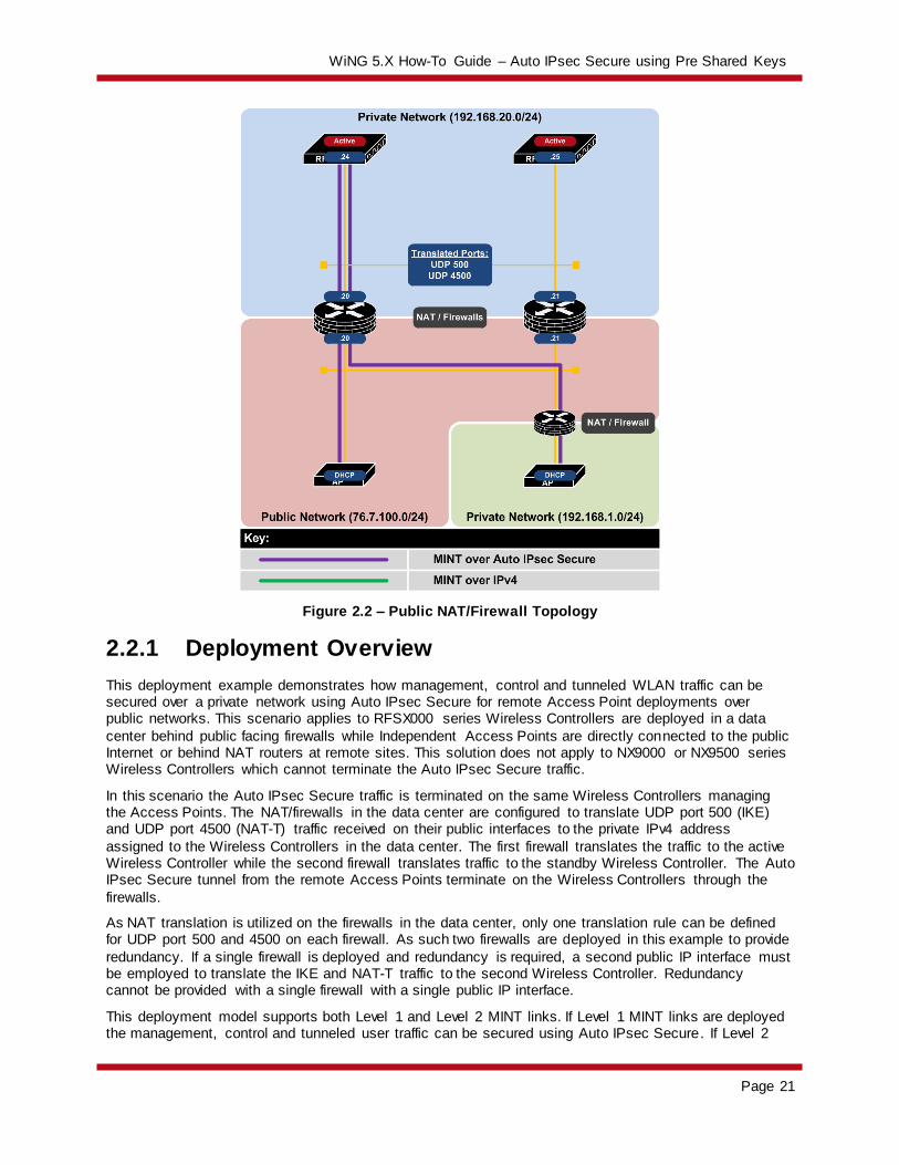
Figure 2.2 – Public NAT/Firewall Topology
2.2.1 Deployment Overview
This deployment example demonstrates how management, control and tunneled WLAN traffic can be secured over a private network using Auto IPsec Secure for remote Access Point deployments over public networks. This scenario applies to RFSX000 series Wireless Controllers are deployed in a data
center behind public facing firewalls while Independent Access Points are directly connected to the public Internet or behind NAT routers at remote sites. This solution does not apply to NX9000 or NX9500 series Wireless Controllers which cannot terminate the Auto IPsec Secure traffic.
In this scenario the Auto IPsec Secure traffic is terminated on the same Wireless Controllers managing the Access Points. The NAT/firewalls in the data center are configured to translate UDP port 500 (IKE) and UDP port 4500 (NAT-T) traffic received on their public interfaces to the private IPv4 address
assigned to the Wireless Controllers in the data center. The first firewall translates the traffic to the active Wireless Controller while the second firewall translates traffic to the standby Wireless Controller. The Auto IPsec Secure tunnel from the remote Access Points terminate on the Wireless Controllers through the
firewalls.
As NAT translation is utilized on the firewalls in the data center, only one translation rule can be defined for UDP port 500 and 4500 on each firewall. As such two firewalls are deployed in this example to provide
redundancy. If a single firewall is deployed and redundancy is required, a second public IP interface must be employed to translate the IKE and NAT-T traffic to the second Wireless Controller. Redundancy cannot be provided with a single firewall with a single public IP interface.
This deployment model supports both Level 1 and Level 2 MINT links. If Level 1 MINT links are deployed the management, control and tunneled user traffic can be secured using Auto IPsec Secure. If Level 2

WiNG 5.X How-To Guide – Auto IPsec Secure using Pre Shared Keys
Page 22
MINT links are deployed, only management and control traffic can be secured as tunneling user traffic is not supported over Level 2 MINT links.
2.2.1.1 Remote Access Point Deployments
For remote Access Point deployments over a public network you cannot control the DHCP or DNS parameters the Access Points receive to automate the initial discovery of the Wireless Controller(s). Additionally the Wireless Controller(s) in the data center are only reachable over the public Internet via
the Auto IPsec Secure tunnel. As such the remote Access Points will require pre-staging prior to deployment so that they have the necessary Group ID, Authentication Key and Controller Host entries before that they can initiate the Auto IPsec Secure tunnel and adopt.
The remote Access Points will typically receive IP addressing either directly from the Internet Service Provider (ISP), 3G / 4G Provider or the NAT router at the remote site. A static IP addressing can also be defined if required and learned by the Wireless Controller(s) during adoption and added to the device
configuration as an override.
To initiate the Auto IPsec Secure tunnel, the Access Points will require the Group ID, Authentication Key and static Controller Host entries to be pre-defined on each Access Point. This information can be pre-
configured prior to shipping the Access Point to the remote site or performed locally at the remote site prior to deployment.
When the remote Access Points are deployed behind a NAT device, the source IP address must be unique for each Access Point. The ability to support remote Access Points with the same private IP address is not supported in the WiNG 5.3 release. This limitation will be addressed in a future release.
2.2.1.2 Failover and Recovery
For public network deployments with NAT firewalls, a cluster of Wireless Controllers will be deployed in
the data center in an active / active or active / standby state. In an active / active deployment both Wireless Controllers are able to adopt and manage Access Points over Auto IPsec Secure. In an active / standby deployment only the active Wireless Controller can adopt and manage Access Points over Auto
IPsec Secure. The standby Wireless Controller will only become active in the event of a primary Controller failure.
The Access Points have two static Controller Host entries defined in their assigned profile which provides
the private IP addresses or hostnames of both the Wireless Controllers in the data center in addition to the public IP addresses or hostnames of the firewalls translating the IKE and IPsec traffic to the Wireless Controllers:
Host Entry 1 – Includes the private IP address of the primary Controller and the public IP address of the firewall translating the traffic to the primary Controller.
Host Entry 2 – Includes the private IP address of the secondary Controller and the public IP
address of the firewall translating the traffic to the secondary Controller.
If both Wireless Controllers are operating in an active mode, the remote Access Points can potentially adopt to each Wireless Controllers based on each Wireless Controllers load. Alternatively Access Points
can be steered to a specific Wireless Controller using the Preferred Controller Group parameter.
If only one Wireless Controller is active in the data center, all the Access Points will adopt to the active Wireless Controller. If the active Wireless Controller fails or is taken down for maintenance, the Access
Points will failover to the standby Wireless Controller.

WiNG 5.X How-To Guide – Auto IPsec Secure using Pre Shared Keys
Page 23
Figure 2.2.1.2 – Failover and Recovery using NAT/Firewalls
For remote Access Point deployments using Level 2 MINT links, each remote Access Point will initially
establish an Auto IPsec Secure tunnel to the active Wireless Controller in the data center. Upon adoption and configuration the remote Access Points will elect an RF Domain Manager for the site. All remote Access Points except the elected RF Domain Managers will tear down their Auto IPsec Secure Tunnels.
Only the elected RF Domain Managers will maintain an active Auto IPsec Secure tunnel to the active Wireless Controller.
WiNG 5.X How-To Guide – Auto IPsec Secure using Pre Shared Keys
Page 24
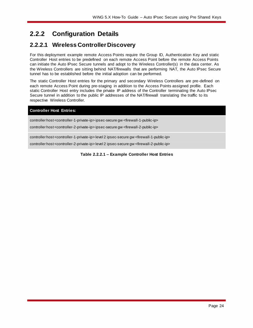
2.2.2 Configuration Details
2.2.2.1 Wireless Controller Discovery
For this deployment example remote Access Points require the Group ID, Authentication Key and static Controller Host entries to be predefined on each remote Access Point before the remote Access Points can initiate the Auto IPsec Secure tunnels and adopt to the Wireless Controller(s) in the data center. As
the Wireless Controllers are sitting behind NAT/firewalls that are performing NAT, the Auto IPsec Secure tunnel has to be established before the initial adoption can be performed.
The static Controller Host entries for the primary and secondary Wireless Controllers are pre-defined on
each remote Access Point during pre-staging in addition to the Access Points assigned profile. Each static Controller Host entry includes the private IP address of the Controller terminating the Auto IPsec Secure tunnel in addition to the public IP addresses of the NAT/firewall translating the traffic to its
respective Wireless Controller.
Controller Host Entries:
controller host <controller-1-private-ip> ipsec-secure gw <firewall-1-public-ip>
controller host <controller-2-private-ip> ipsec-secure gw <firewall-2-public-ip>
controller host <controller-1-private-ip> level 2 ipsec-secure gw <firewall-1-public-ip>
controller host <controller-2-private-ip> level 2 ipsec-secure gw <firewall-2-public-ip>
Table 2.2.2.1 – Example Controller Host Entries

WiNG 5.X How-To Guide – Auto IPsec Secure using Pre Shared Keys
Page 25
2.2.2.2 Access Point Profile
Upon adoption the Access Points are assigned a Profile which contains the Auto IPsec Secure Group ID and Authentication Key in addition to static Controller Host entries. The following provides an overview of the key configuration parameters in the Access Point Profile required for Auto IPsec Secure operation
over a public network when NAT/firewalls are deployed in the data center between the Access Points and the Wireless Controllers:
1 The Access Point Profile contains static Controller Host entries for each Wireless Controller
in the Data Center. Each Controller Host entry includes a Wireless Controllers IP address or hostname, MINT Routing Level (Level 1 in this example) and is enabled for Auto IPsec Secure . Additionally the ublic IP address or hostname of the public Interface(s) on the NAT/firewalls
performing the NAT translation are defined in the IPsec GW fields:
Configuration Profiles <ap-profile-name> Adoption
WiNG 5.X How-To Guide – Auto IPsec Secure using Pre Shared Keys
Page 26
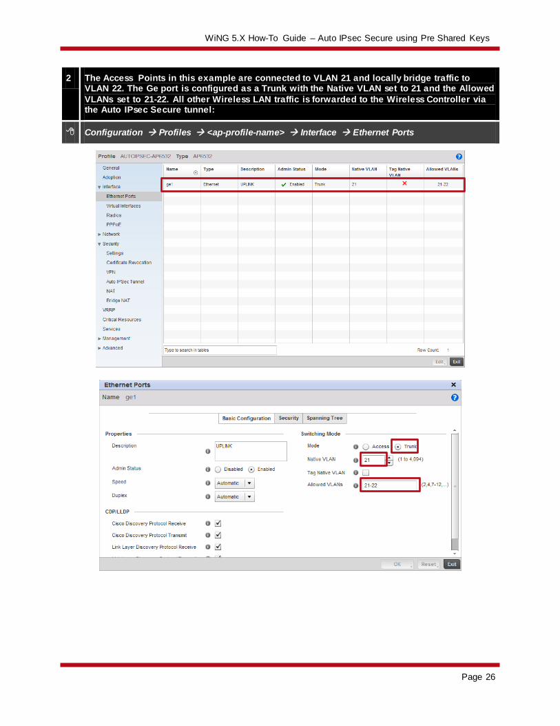
2 The Access Points in this example are connected to VLAN 21 and locally bridge traffic to VLAN 22. The Ge port is configured as a Trunk with the Native VLAN set to 21 and the Allowed
VLANs set to 21-22. All other Wireless LAN traffic is forwarded to the Wireless Controller via the Auto IPsec Secure tunnel:
Configuration Profiles <ap-profile-name> Interface Ethernet Ports
WiNG 5.X How-To Guide – Auto IPsec Secure using Pre Shared Keys
Page 27
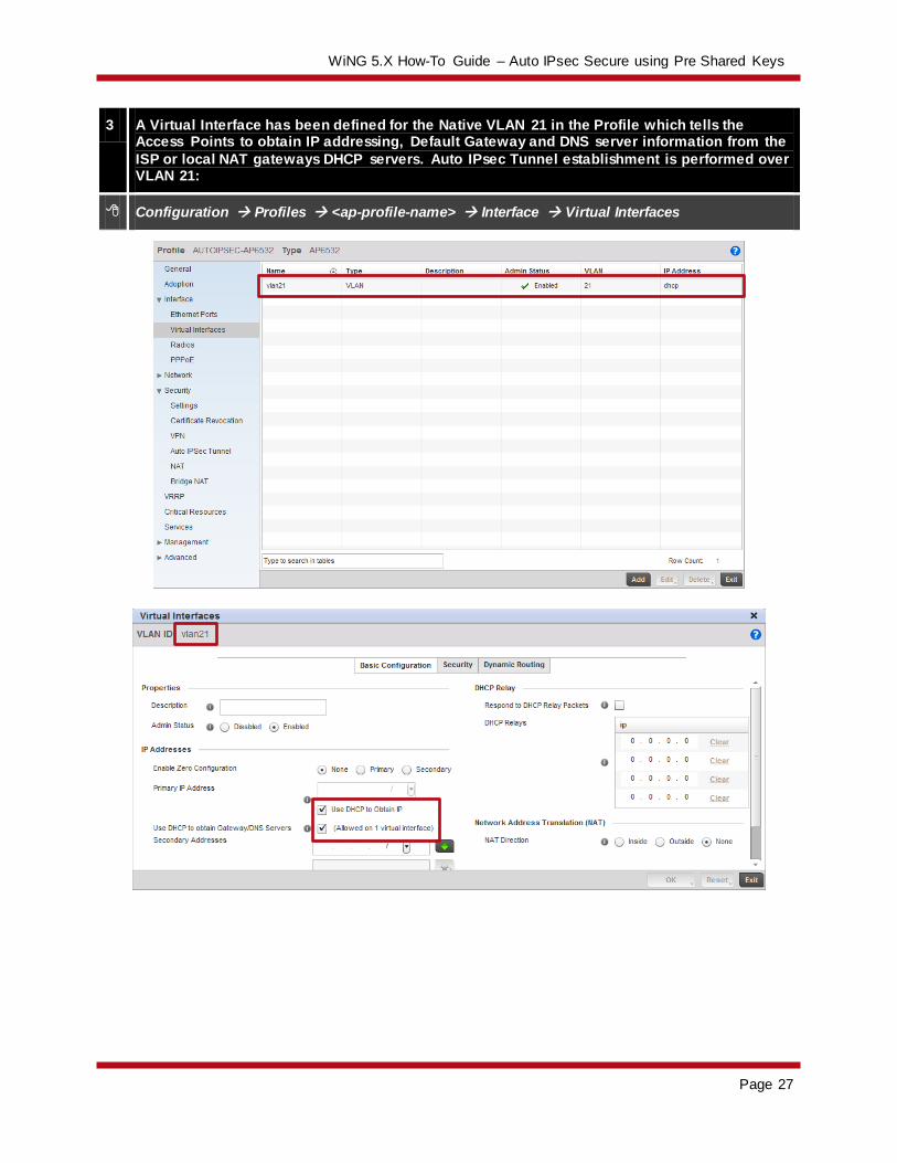
3 A Virtual Interface has been defined for the Native VLAN 21 in the Profile which tells the Access Points to obtain IP addressing, Default Gateway and DNS server information from the
ISP or local NAT gateways DHCP servers. Auto IPsec Tunnel establishment is performed over VLAN 21:
Configuration Profiles <ap-profile-name> Interface Virtual Interfaces

WiNG 5.X How-To Guide – Auto IPsec Secure using Pre Shared Keys
Page 28
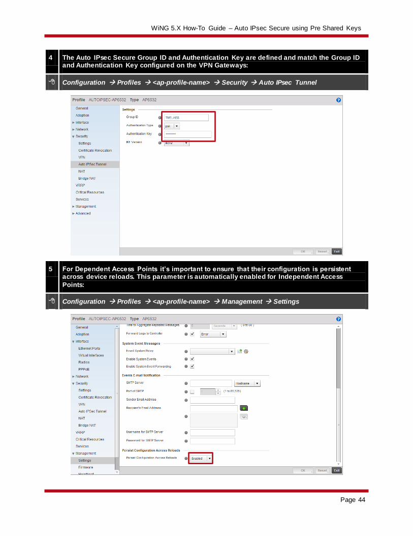
4 The Auto IPsec Secure Group ID and Authentication Key are defined and match the Group ID and Authentication Key configured in the Wireless Controller Profile:
Configuration Profiles <ap-profile-name> Security Auto IPsec Tunnel
5 For Dependent Access Points it’s important to ensure that their configuration is persistent across device reloads. This parameter is automatically enabled for Independent Access
Points:
Configuration Profiles <ap-profile-name> Management Settings
WiNG 5.X How-To Guide – Auto IPsec Secure using Pre Shared Keys
Page 29
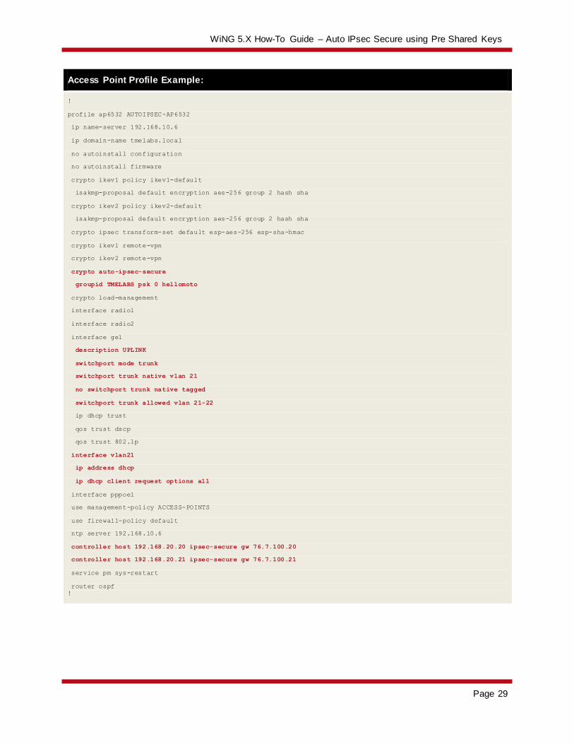
Access Point Profile Example:
!
profile ap6532 AUTOIPSEC-AP6532
ip name-server 192.168.10.6
ip domain-name tmelabs.local
no autoinstall configuration
no autoinstall firmware
crypto ikev1 policy ikev1-default
isakmp-proposal default encryption aes-256 group 2 hash sha
crypto ikev2 policy ikev2-default
isakmp-proposal default encryption aes-256 group 2 hash sha
crypto ipsec transform-set default esp-aes-256 esp-sha-hmac
crypto ikev1 remote-vpn
crypto ikev2 remote-vpn
crypto auto-ipsec-secure
groupid TMELABS psk 0 hellomoto
crypto load-management
interface radio1
interface radio2
interface ge1
description UPLINK
switchport mode trunk
switchport trunk native vlan 21
no switchport trunk native tagged
switchport trunk allowed vlan 21-22
ip dhcp trust
qos trust dscp
qos trust 802.1p
interface vlan21
ip address dhcp
ip dhcp client request options all
interface pppoe1
use management-policy ACCESS-POINTS
use firewall-policy default
ntp server 192.168.10.6
controller host 192.168.20.20 ipsec-secure gw 76.7.100.20
controller host 192.168.20.21 ipsec-secure gw 76.7.100.21
service pm sys-restart
router ospf
!
WiNG 5.X How-To Guide – Auto IPsec Secure using Pre Shared Keys
Page 30
2.2.2.3 Wireless Controller Profile
The Wireless Controllers in the data center terminate the Auto IPsec Secure tunnels from the Access Points over the private network. The following provides an overview of the key configuration parameters in the Wireless Controller Profile required for Auto IPsec Secure operation over a public network:
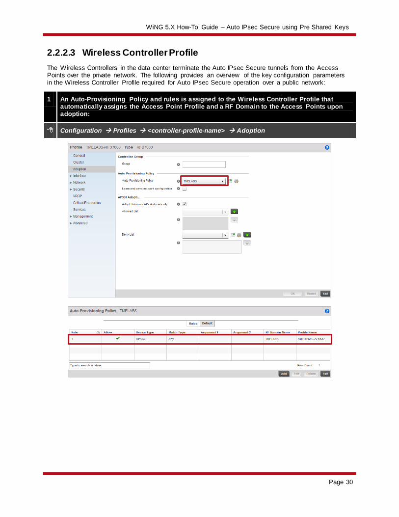
1 An Auto-Provisioning Policy and rules is assigned to the Wireless Controller Profile that automatically assigns the Access Point Profile and a RF Domain to the Access Points upon adoption:
Configuration Profiles <controller-profile-name> Adoption

WiNG 5.X How-To Guide – Auto IPsec Secure using Pre Shared Keys
Page 31
2 For Independent Access Points, the Wireless Controller Profile is optionally enabled to ignore any configuration pre-defined on the Access Points. This ensures no configuration
parameters are learned from the Dependent Access Points upon adoption and added to the Access Points device configuration as overrides:
Configuration Profiles <controller-profile-name> Adoption
2 The Auto IPsec Secure Group ID and Authentication Key are defined and match the Group ID and Authentication Key configured in the Access Point Profile:
Configuration Profiles <controller-profile-name> Security Auto IPsec Tunnel

WiNG 5.X How-To Guide – Auto IPsec Secure using Pre Shared Keys
Page 32
Wireless Controller Profile Example:
!
profile rfs7000 TMELABS-RFS7000
ip name-server 192.168.10.6
ip domain-name tmelabs.local
no autoinstall configuration
no autoinstall firmware
crypto ikev1 policy ikev1-default
isakmp-proposal default encryption aes-256 group 2 hash sha
crypto ikev2 policy ikev2-default
isakmp-proposal default encryption aes-256 group 2 hash sha
crypto ipsec transform-set default esp-aes-256 esp-sha-hmac
crypto ikev1 remote-vpn
crypto ikev2 remote-vpn
crypto auto-ipsec-secure
groupid TMELABS psk 0 hellomoto
interface ge1
description UPLINK
switchport mode trunk
switchport trunk native vlan 20
switchport trunk native tagged
switchport trunk allowed vlan 20,23-25
ip dhcp trust
qos trust dscp
qos trust 802.1p
!
! Unnecessary Configuration Removed for Brevity
!
use management-policy WIRELESS-CONTROLLERS
use firewall-policy default
use auto-provisioning-policy TMELABS
ntp server 192.168.10.6
no auto-learn-staging-config
service pm sys-restart
!
Auto-Provisioning Policy Example:
!
auto-provisioning-policy TMELABS
adopt ap6532 precedence 1 profile AUTOIPSEC-AP6532 rf-domain TMELABS any
!

WiNG 5.X How-To Guide – Auto IPsec Secure using Pre Shared Keys
Page 33
2.2.2.4 Access Point Pre Staging
As the remote Access Points are deployed over a public network, their Auto IPsec Secure configuration needs to be pre-staged prior to deployment. Without pre-staging the remote Access Points will not have the necessary information required to establish the Auto IPsec Secure tunnel and adopt to the Wireless
Controllers in the data center.
The following provides an overview of the key configuration parameters that must be pre-defined on each remote Access Points prior to deployment:
1. The Access Point firmware must be running WiNG 5.3.1 or higher to support Auto IPsec Secure.
2. The remote Access Points require IP addressing to be able to communicate over the intermediate network:
a. DHCP – By default each Access Point will obtain dynamic network addressing using DHCP over VLAN 1.
b. PPPoE – The PPPoE service information, credentials and SVI must be pre-defined on
the Access Point as an override.
c. Static – A SVI with static IP address, subnet mask and default-gateway must be pre-defined on the Access Point as an override.
3. The common Group ID and Authentication Key that matches the values defined in the Access Point must be predefined.
4. Static Controller Host entries that match the values defined in the Access Point profile must be
are pre-defined.
By default all Access Points are pre-configured to obtain dynamic IP addressing from a DHCP server over VLAN 1. If IPv4 addressing is being provided using DHCP, only the Group ID, Authentication Key and
static Controller Host entries need to be pre-defined. Upon Auto IPsec Secure tunnel establishment and adoption, the remote Access Point will receive its configuration from its profile which includes the switchport / DHCP configuration, Auto IPsec Secure Group ID, Authentication Key and static Controller
Host entries.
For PPPoE or static IP deployments, these parameters will need to be pre-defined on the remote Access Points prior to deployment before the remote Access Point will be able to communicate over the
intermediate network. These network parameters can be defined directly on the Access Point as overrides and be learned by the Wireless Controllers upon adoption. Learning of pre-staged configuration will require the auto-learn-staging-config parameter is enabled in the Wireless Controller profile.
Upon successful Auto IPsec Secure tunnel establishment and adoption, the remote Access Point’s device configuration will be added to the master configuration as overrides. The Access Point will receive its configuration from its profile which includes the Auto IPsec Secure Group ID, Authentication Key and
static Controller Host entries.

WiNG 5.X How-To Guide – Auto IPsec Secure using Pre Shared Keys
Page 34
Pre-Staged Configuration Example (DHCP):
!
ap6532 5C-0E-8B-A4-48-80
use profile default-ap6532
use rf-domain default
hostname ap6532-A44880
crypto auto-ipsec-secure
remotegw ike-version ikev2
groupid TMELABS psk 0 hellomoto
logging on
logging console warnings
logging buffered warnings
controller host 192.168.20.20 ipsec-secure gw 76.7.100.20
controller host 192.168.20.21 ipsec-secure gw 76.7.100.21
!
Pre-Staged Configuration Example (Static IP):
!
ap6532 5C-0E-8B-A4-48-80
use profile default-ap6532
use rf-domain default
hostname ap6532-A44880
ip default-gateway 76.7.100.1
crypto auto-ipsec-secure
remotegw ike-version ikev2
groupid TMELABS psk 0 hellomoto
interface vlan1
ip address 76.7.100.90/24
logging on
logging console warnings
logging buffered warnings
controller host 192.168.20.20 ipsec-secure gw 76.7.100.20
controller host 192.168.20.21 ipsec-secure gw 76.7.100.21
!

WiNG 5.X How-To Guide – Auto IPsec Secure using Pre Shared Keys
Page 35
Pre-Staged Configuration Example (PPPoE):
!
use profile default-ap6532
use rf-domain default
hostname ap6532-A4AABB
crypto auto-ipsec-secure
remotegw ike-version ikev2
groupid TMELABS psk 0 hellomoto
interface ge1
switchport mode access
switchport access vlan 4094
interface vlan4094
interface pppoe1
auth-type pap
username [email protected]
password hellomoto
service-name ISP-Name
local-net vlan 4094
controller host 192.168.20.20 ipsec-secure gw 76.7.100.20
controller host 192.168.20.21 ipsec-secure gw 76.7.100.21
!

WiNG 5.X How-To Guide – Auto IPsec Secure using Pre Shared Keys
Page 36
2.3 Public Network Deployments with VPN Gateways
For this scenario the Access Points are deployed at remote sites over the public Internet while the RFSX000 / NX000 Wireless Controllers are deployed in the data center behind one or more VPN
Gateways. The remote Access Points are either directly connected to the public Internet or are deployed behind a NAT router at the remote site.
The remote Access Points are adopted and managed over Level 1 or Level 2 MINT links which are
secured using an Auto IPsec Secure tunnels that are terminated on public facing VPN gateways in the data center. One VPN gateway terminates traffic for the active Controller while the second VPN gateway terminates traffic for the standby Controller.
The following provides a summary of this deployment example:
1. The VPN gateways are configured with the following parameters to terminate the Auto IPsec Secure traffic:
a. The appropriate ACL rules to permit IP traffic from the Controller subnet to the public Internet (any).
b. An IKEv2 proposal supporting AES 256 encryption, Diffie Hellman Group 2 and SHA1
authentication.
c. An IKEv2 peer supporting any remote device (0.0.0.0) with the Remote and Local IDs set to match the Group ID defined in the Access Point profile. The Authentication Key (PSK)
is also set to match the Authentication Key defined in the Access Point profile.
2. The Access Points obtain dynamic IPv4 addressing from the ISP or NAT router on VLAN 21 at the remote site or are statically addressed.
3. A common Group ID, Authentication Key and static Controller Host entries are defined in the Access Point profile(s). These parameters will establish the IPsec tunnel and initiate adoption to an active Wireless Controller.
4. A common Group ID, Authentication Key and static Controller Host entries are pre-defined on each remote Access Point as overrides.

WiNG 5.X How-To Guide – Auto IPsec Secure using Pre Shared Keys
Page 37
Figure 2.3 – Public VPN Gateway Topology
2.3.1 Deployment Overview
This deployment example demonstrates how management, control and tunneled WLAN traffic can be secured over a private network using Auto IPsec Secure for remote Access Point deployments over
public networks. This scenario applies to RFSX000 or NX9000 Wireless Controllers deployed in a data center behind public facing VPN gateways while Independent Access Points are directly connected to the public Internet or behind NAT routers at remote sites.
In this scenario the VPN gateways are configured to terminate the Auto IPsec Secure tunnels on their public interfaces. The first VPN gateway terminates traffic destined to the active Wireless Controller while the second VPN gateway terminates traffic destined to the standby Wireless Controller. The Auto IPsec
Secure tunnel from the remote Access Points terminate on the VPN gateways and MINT is forwarded form the VPN gateways un-encrypted to the Wireless Controllers.
While a single VPN gateway can be deployed to support multiple Wireless Controllers in the data center,
two VPN gateways are utilized in this example for redundancy. If the primary VPN gateway becomes un-reachable, the Auto IPsec Secure tunnels will failover to the secondary VPN gateway and adopt to the standby Wireless Controller.
This deployment model supports both Level 1 and Level 2 MINT links. If Level 1 MINT links are deployed the management, control and tunneled user traffic can be secured using Auto IPsec Secure. If Level 2 MINT links are deployed, only management and control traffic can be secured as tunneling user traffic is
not supported over Level 2 MINT links.

WiNG 5.X How-To Guide – Auto IPsec Secure using Pre Shared Keys
Page 38
2.3.1.1 Remote Access Point Deployments
For remote Access Point deployments over a public network you cannot control the DHCP or DNS parameters the Access Points receive to automate the initial discovery of the Wireless Controller(s). Additionally the Wireless Controller(s) in the data center are only reachable over the public Internet via
the Auto IPsec Secure tunnel. As such the remote Access Points will require pre-staging prior to deployment so that they have the necessary Group ID, Authentication Key and Controller Host entries before that they can initiate the Auto IPsec Secure tunnel and adopt.
The remote Access Points will typically receive IP addressing either directly from the Internet Service Provider (ISP), 3G / 4G Provider or the NAT router at the remote site. A static IP addressing can also be defined if required and learned by the Wireless Controller(s) during adoption and added to the device
configuration as an override.
To initiate the Auto IPsec Secure tunnel, the Access Points will require the Group ID, Authentication Key and static Controller Host entries to be pre-defined on each Access Point. This information can be pre-
configured prior to shipping the Access Point to the remote s ite or performed locally at the remote site prior to deployment.
When the remote Access Points are deployed behind a NAT device, the source IP address must be unique for each Access Point. The ability to support remote Access Points with the same private IP address is not supported in the WiNG 5.3 release. This limitation will be addressed in a future release.
2.3.1.2 Failover and Recovery
For public network deployments with VPN gateways, a cluster of Wireless Controllers will be deployed in
the data center in an active / active or active / standby state. In an active / active deployment both Wireless Controllers are able to adopt and manage Access Points using MINT. In an active / standby deployment only the active Wireless Controller can adopt and manage Access . The standby Wireless
Controller will only become active in the event of a primary Controller failure.
The Access Points have two static Controller Host entries defined in their assigned profile which provides the private IP addresses or hostnames of both the Wireless Controllers in the data center in addition to
the public IP addresses or hostnames of the VPN gateways terminating the IKEv2 and IPsec traffic:
Host Entry 1 – Includes the private IP address of the primary Controller and the public IP address of the primary VPN gateway terminating the traffic to the primary Controller.
Host Entry 2 – Includes the private IP address of the secondary Controller and the public IP address of the secondary VPN gateway terminating the traffic to the standby Controller.
If both Wireless Controllers are operating in an active mode, the remote Access Points can potentially
adopt to each Wireless Controllers based on each Wireless Controllers load. Alternatively Access Points can be steered to a specific Wireless Controller using the Preferred Controller Group parameter.
If only one Wireless Controller is active in the data center, all the Access Points will adopt to the active
Wireless Controller. If the active Wireless Controller fails or is taken down for maintenance, the Access Points will failover to the standby Wireless Controller.

WiNG 5.X How-To Guide – Auto IPsec Secure using Pre Shared Keys
Page 39
Figure 2.3.1.2 – Failover and Recovery using VPN Gateways
For remote Access Point deployments using Level 2 MINT links, each remote Access Point will initially
establish an Auto IPsec Secure tunnel to the active Wireless Controller in the data center. Upon adoption and configuration the remote Access Points will elect an RF Domain Manager for the site. All remote Access Points except the elected RF Domain Managers will tear down their Auto IPsec Secure Tunnels.
Only the elected RF Domain Managers will maintain an active Auto IPsec Secure tunnel to the active Wireless Controller.

WiNG 5.X How-To Guide – Auto IPsec Secure using Pre Shared Keys
Page 40
2.3.2 Configuration Details
2.3.2.1 Wireless Controller Discovery
For this deployment example remote Access Points require the Group ID, Authentication Key and static Controller Host entries to be predefined on each remote Access Point before the remote Access Points can initiate the Auto IPsec Secure tunnels to the VPN gateways and adopt to the Wireless Controller(s) in
the data center. As the Wireless Controllers are sitting behind the VPN gateways, the Auto IPsec Secure tunnel has to be established before the initial adoption can be performed.
The static Controller Host entries for the primary and secondary Wireless Controllers are pre-defined on
each remote Access Point during pre-staging in addition to the Access Points assigned profile. Each static Controller Host entry includes the private IP address of the Controller terminating adopting the Access Points in addition to the public IP addresses or hostname of the VPN gateway terminating the
Auto IPsec Secure tunnel.
Controller Host Entries:
controller host <controller-1-private-ip> ipsec-secure gw <vpn-gw-1-public-ip>
controller host <controller-2-private-ip> ipsec-secure gw <vpn-gw--2-public-ip>
controller host <controller-1-private-ip> level 2 ipsec-secure gw <vpn-gw-1-public-ip>
controller host <controller-2-private-ip> level 2 ipsec-secure gw <vpn-gw-2-public-ip>
Table 2.3.2.1 – Example Controller Host Entries

WiNG 5.X How-To Guide – Auto IPsec Secure using Pre Shared Keys
Page 41
2.3.2.2 Access Point Profile
Upon adoption the Access Points are assigned a Profile which contains the Auto IPsec Secure Group ID and Authentication Key in addition to static Controller Host entries. The following provides an overview of the key configuration parameters in the Access Point Profile required for Auto IPsec Secure operation
over a public network when VPN gateways are deployed in the data center between the Access Points and the Wireless Controllers:
1 The Access Point Profile contains static Controller Host entries for each Wireless Controller
in the Data Center. Each Controller Host entry includes a Wireless Controllers IP address or hostname, MINT Routing Level (Level 1 in this example) and is enabled for Auto IPsec Secure. Additionally the IP address or hostname of the public Interface(s) on the VPN gateways
terminating the IPsec tunnels are defined in the IPsec GW fields:
Configuration Profiles <ap-profile-name> Adoption

WiNG 5.X How-To Guide – Auto IPsec Secure using Pre Shared Keys
Page 42
2 The Access Points in this example are connected to VLAN 21 and locally bridge traffic to VLAN 22. The Ge port is configured as a Trunk with the Native VLAN set to 21 and the Allowed
VLANs set to 21-22. All other Wireless LAN traffic is forwarded to the Wireless Controller via the Auto IPsec Secure tunnel:
Configuration Profiles <ap-profile-name> Interface Ethernet Ports

WiNG 5.X How-To Guide – Auto IPsec Secure using Pre Shared Keys
Page 43
3 A Virtual Interface has been defined for the Native VLAN 21 in the Profile which tells the Access Points to obtain IP addressing, Default Gateway and DNS server information from the
ISP or local NAT gateways DHCP server:
Configuration Profiles <ap-profile-name> Interface Virtual Interfaces
WiNG 5.X How-To Guide – Auto IPsec Secure using Pre Shared Keys
Page 44
4 The Auto IPsec Secure Group ID and Authentication Key are defined and match the Group ID and Authentication Key configured on the VPN Gateways:
Configuration Profiles <ap-profile-name> Security Auto IPsec Tunnel
5 For Dependent Access Points it’s important to ensure that their configuration is persistent across device reloads. This parameter is automatically enabled for Independent Access
Points:
Configuration Profiles <ap-profile-name> Management Settings

WiNG 5.X How-To Guide – Auto IPsec Secure using Pre Shared Keys
Page 45
Access Point Profile Example:
!
profile ap6532 AUTOIPSEC-AP6532
ip name-server 192.168.10.6
ip domain-name tmelabs.local
no autoinstall configuration
no autoinstall firmware
crypto ikev1 policy ikev1-default
isakmp-proposal default encryption aes-256 group 2 hash sha
crypto ikev2 policy ikev2-default
isakmp-proposal default encryption aes-256 group 2 hash sha
crypto ipsec transform-set default esp-aes-256 esp-sha-hmac
crypto ikev1 remote-vpn
crypto ikev2 remote-vpn
crypto auto-ipsec-secure
groupid TMELABS psk 0 hellomoto
crypto load-management
interface radio1
interface radio2
interface ge1
description UPLINK
switchport mode trunk
switchport trunk native vlan 21
no switchport trunk native tagged
switchport trunk allowed vlan 21-22
ip dhcp trust
qos trust dscp
qos trust 802.1p
interface vlan21
ip address dhcp
ip dhcp client request options all
interface pppoe1
use management-policy ACCESS-POINTS
use firewall-policy default
ntp server 192.168.10.6
controller host 192.168.20.20 ipsec-secure gw 76.7.100.20
controller host 192.168.20.21 ipsec-secure gw 76.7.100.21
service pm sys-restart
router ospf
!
WiNG 5.X How-To Guide – Auto IPsec Secure using Pre Shared Keys
Page 46
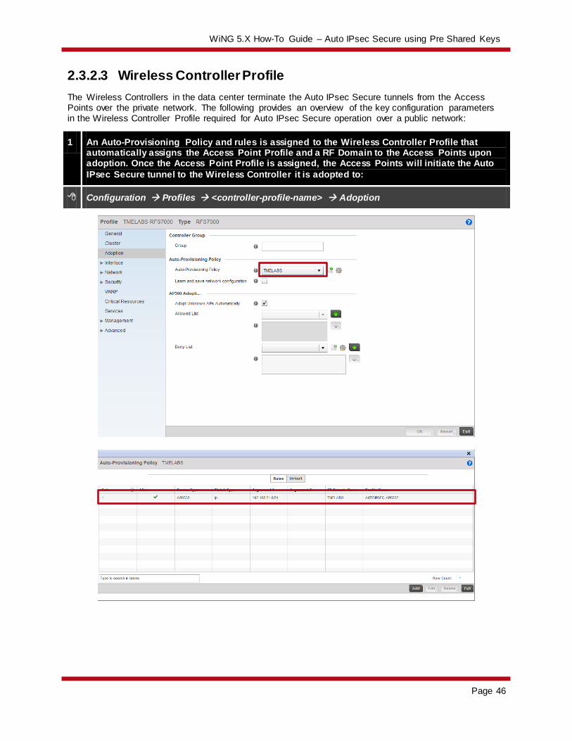
2.3.2.3 Wireless Controller Profile
The Wireless Controllers in the data center terminate the Auto IPsec Secure tunnels from the Access Points over the private network. The following provides an overview of the key configuration parameters in the Wireless Controller Profile required for Auto IPsec Secure operation over a public network:
1 An Auto-Provisioning Policy and rules is assigned to the Wireless Controller Profile that automatically assigns the Access Point Profile and a RF Domain to the Access Points upon adoption. Once the Access Point Profile is assigned, the Access Points will initiate the Auto
IPsec Secure tunnel to the Wireless Controller it is adopted to:
Configuration Profiles <controller-profile-name> Adoption

WiNG 5.X How-To Guide – Auto IPsec Secure using Pre Shared Keys
Page 47
2 For Independent Access Points, the Wireless Controller Profile is configured to ignore any configuration pre-defined on the Access Points. This ensures no configuration parameters
are learned from the Dependent Access Points upon adoption and added to the Access Points device configuration as overrides:
Configuration Profiles <controller-profile-name> Adoption

WiNG 5.X How-To Guide – Auto IPsec Secure using Pre Shared Keys
Page 48
Wireless Controller Profile Example:
!
profile rfs7000 TMELABS-RFS7000
ip name-server 192.168.10.6
ip domain-name tmelabs.local
no autoinstall configuration
no autoinstall firmware
crypto ikev1 policy ikev1-default
isakmp-proposal default encryption aes-256 group 2 hash sha
crypto ikev2 policy ikev2-default
isakmp-proposal default encryption aes-256 group 2 hash sha
crypto ipsec transform-set default esp-aes-256 esp-sha-hmac
crypto ikev1 remote-vpn
crypto ikev2 remote-vpn
interface ge1
description UPLINK
switchport mode trunk
switchport trunk native vlan 20
switchport trunk native tagged
switchport trunk allowed vlan 20,23-25
ip dhcp trust
qos trust dscp
qos trust 802.1p
!
! Unnecessary Configuration Removed for Brevity
!
use management-policy WIRELESS-CONTROLLERS
use firewall-policy default
use auto-provisioning-policy TMELABS
ntp server 192.168.10.6
no auto-learn-staging-config
service pm sys-restart
!
Auto-Provisioning Policy Example:
!
auto-provisioning-policy TMELABS
adopt ap6532 precedence 1 profile AUTOIPSEC-AP6532 rf-domain TMELABS ip 192.168.21.0/24
!

WiNG 5.X How-To Guide – Auto IPsec Secure using Pre Shared Keys
Page 49
2.3.2.4 Access Point Pre Staging
As the remote Access Points are deployed over a public network, their Auto IPsec Secure configuration needs to be pre-staged prior to deployment. Without pre-staging the remote Access Points will not have the necessary information required to establish the Auto IPsec Secure tunnel and adopt to the Wireless
Controllers in the data center.
The following provides an overview of the key configuration parameters that must be pre-defined on each remote Access Points prior to deployment:
1. The Access Point firmware must be running WiNG 5.3.1 or higher.
2. The remote Access Points require IP addressing to be able to communicate over the intermediate network:
a. DHCP – By default each Access Point will obtain dynamic network addressing using DHCP over VLAN 1.
b. PPPoE – The PPPoE service information, credentials and SVI must be pre-defined on
the Access Point as an override.
c. Static – A SVI with static IP address, subnet mask and default-gateway must be pre-defined on the Access Point as an override.
3. The common Group ID and Authentication Key that matches the values defined in the Access Point must be predefined.
4. Static Controller Host entries that match the values defined in the Access Point profile must be
are pre-defined.
By default all Access Points are pre-configured to obtain dynamic IP addressing from a DHCP server over VLAN 1. If IPv4 addressing is being provided using DHCP, only the Group ID, Authentication Key and
static Controller Host entries need to be pre-defined. Upon Auto IPsec Secure tunnel establishment and adoption, the remote Access Point will receive its configuration from its profile which includes the switchport / DHCP configuration, Auto IPsec Secure Group ID, Authentication Key and static Controller
Host entries.
For PPPoE or static IP deployments, these parameters will need to be pre-defined on the remote Access Points prior to deployment before the remote Access Point will be able to communicate over the
intermediate network. These network parameters can be defined directly on the Access Point as overrides and be learned by the Wireless Controllers upon adoption. Learning of pre-staged configuration will require the auto-learn-staging-config parameter is enabled in the Wireless Controller profile.
Upon successful Auto IPsec Secure tunnel establishment and adoption, the remote Access Point’s device configuration will be added to the master configuration as overrides. The Access Point will receive its configuration from its profile which includes the Auto IPsec Secure Group ID, Authentication Key and
static Controller Host entries.

WiNG 5.X How-To Guide – Auto IPsec Secure using Pre Shared Keys
Page 50
Pre-Staged Configuration Example (DHCP):
!
ap6532 5C-0E-8B-A4-48-80
use profile default-ap6532
use rf-domain default
hostname ap6532-A44880
crypto auto-ipsec-secure
remotegw ike-version ikev2
groupid TMELABS psk 0 hellomoto
logging on
logging console warnings
logging buffered warnings
controller host 192.168.20.20 ipsec-secure gw 76.7.100.20
controller host 192.168.20.21 ipsec-secure gw 76.7.100.21
!
Pre-Staged Configuration Example (Static IP):
!
ap6532 5C-0E-8B-A4-48-80
use profile default-ap6532
use rf-domain default
hostname ap6532-A44880
ip default-gateway 76.7.100.1
crypto auto-ipsec-secure
remotegw ike-version ikev2
groupid TMELABS psk 0 hellomoto
interface vlan1
ip address 76.7.100.90/24
logging on
logging console warnings
logging buffered warnings
controller host 192.168.20.20 ipsec-secure gw 76.7.100.20
controller host 192.168.20.21 ipsec-secure gw 76.7.100.21
!

WiNG 5.X How-To Guide – Auto IPsec Secure using Pre Shared Keys
Page 51
Pre-Staged Configuration Example (PPPoE):
!
use profile default-ap6532
use rf-domain default
hostname ap6532-A4AABB
crypto auto-ipsec-secure
remotegw ike-version ikev2
groupid TMELABS psk 0 hellomoto
interface ge1
switchport mode access
switchport access vlan 4094
interface vlan4094
interface pppoe1
auth-type pap
username [email protected]
password hellomoto
service-name ISP-Name
local-net vlan 4094
controller host 192.168.20.20 ipsec-secure gw 76.7.100.20
controller host 192.168.20.21 ipsec-secure gw 76.7.100.21
!

WiNG 5.X How-To Guide – Auto IPsec Secure using Pre Shared Keys
Page 52
3. Verification
3.1 Adoption Status
Each active Wireless Controller will display one or more adopted Access Points. Each adopted Access Point should be displayed with a configured state indicating the Access Point has adopted, has received
its configuration and is correctly communicating with the RFSX000 Wireless Controller.
A list of adopted Access Points can be viewed per device using the CLI by issuing the show adoption status on <device-hostname> command:
------------------------------------------------------------------------------------------------------------
HOST-NAME VERSION CFG STAT ADOPTED-BY LAST-ADOPTION UPTIME
------------------------------------------------------------------------------------------------------------
ap6532-1 5.3.1.0-009R configured rfs7000-1 2012-08-09 10:45:19 0 days 00:08:23
ap6532-2 5.3.1.0-009R configured rfs7000-1 2012-08-09 10:45:09 0 days 00:09:05
ap6532-3 5.3.1.0-009R configured rfs7000-1 2012-08-09 10:45:00 0 days 00:09:21
ap6532-4 5.3.1.0-009R configured rfs7000-1 2012-08-09 10:45:11 0 days 00:09:54
ap6532-5 5.3.1.0-009R configured rfs7000-1 2012-08-09 10:45:15 0 days 00:09:16
ap6532-6 5.3.1.0-009R configured rfs7000-1 2012-08-09 10:45:15 0 days 00:09:16
------------------------------------------------------------------------------------------------------------
Total number of APs displayed: 6
A list of adopted Access Points can be viewed per device using the Web-UI by selecting Statistics <rf-
domain-name> <device-hostname> Adoption Access Points:

WiNG 5.X How-To Guide – Auto IPsec Secure using Pre Shared Keys
Page 53
3.2 MINT Links
Each Wireless Controller and Access Point will display one or more MINT links that are secured using IPsec. For campus deployments using Level 1 MINT links, each Access Point will have a secured MINT
link established to a Controller. For remote Access Point deployments using Level 2 MINT links, only the elected RF Domain Managers for each remote site will maintain the secured MINT link. Non RF Domain Managers will only re-establish a secured MINT link if they are elected as the RF Domain Manager for the
remote site.
A list of established MINT links can be viewed per device using the CLI by issuing the show mint links on <device-hostname> command:
7 mint links on 70.38.04.00:
link ip-192.168.20.25:24576 at level 1, 1 adjacencies
link ip-192.168.21.100:24576 at level 1, 1 adjacencies, (secured by ipsec)
link ip-192.168.21.101:24576 at level 1, 1 adjacencies, (secured by ipsec)
link ip-192.168.21.102:24576 at level 1, 1 adjacencies, (secured by ipsec)
link ip-192.168.21.103:24576 at level 1, 1 adjacencies, (secured by ipsec)
link ip-192.168.21.104:24576 at level 1, 1 adjacencies, (secured by ipsec)
link ip-192.168.21.105:24576 at level 1, 1 adjacencies, (secured by ipsec)
3.3 IKEv2 Security Association
Each Access Point will initially establish an IKEv2 security association (SA) to each RFSX000 Wireless Controller defined in the static Controller Host entry. Upon adoption the IKEv2 SA to the non-adopted RFSX000 Wireless Controller will timeout and will be torn down.
The IKEv2 security association is the first phase for establishing an IPsec tunnel with a peer device and security association must be established before the IPsec tunnel (phase II) can be built. If the IKEv2 SA cannot be established, the IPsec tunnel cannot be built and the Access Point will fail adoption.
For campus deployments using Level 1 MINT links, each Access Point will maintain an IKEv2 SA to its adopted RFSX000 Wireless Controller. For remote Access Point deployments using Level 2 MINT links only the elected RF Domain Manager will maintain the IKEv2 SA. Non RF Domain Managers will only re-
establish an IKEv2 security association if they are elected as the RF Domain Manager for the remote site.
A list of established IKE security associations can be viewed per device using the CLI by issuing the show crypto ike sa on <device-hostname> command:
-------------------------------------------------------------------------------
IKE VERSION : IKEv2
Peer Address : 192.168.21.101 Local Address : 192.168.20.24
Encryption Algo : AES_CBC_256
Hash Algo : HMAC_SHA1_96
DH Group : MODP_1024
IKE Lifetime : 2 Hrs 22 Mins 55 Secs
IKE State : ESTABLISHED
-------------------------------------------------------------------------------

WiNG 5.X How-To Guide – Auto IPsec Secure using Pre Shared Keys
Page 54
A list of established IKE security associations can be viewed per device using the Web-UI by selecting Statistics <rf-domain-name> <device-hostname> VPN IKESA:
3.4 IPsec Security Associations
Upon a successful IKE security association (SA), each Access Point will establish an IPsec security
association (SA) to the each RFSX000 Wireless Controller. Upon adoption the IPsec and IKE SAs to the non-adopted RFSX000 Wireless Controller will be torn down. The IPsec tunnel is used to encapsulate MINT management, control and tunneled user traffic.
For campus deployments using Level 1 MINT links, each Access Point will maintain an IPsec SA to its adopted RFSX000 Wireless Controller. For remote Access Point deployments using Level 2 MINT links only the elected RF Domain Manager will maintain the IPsec SA. Non RF Domain Managers will only re-
establish an IPsec SA if they are elected as the RF Domain Manager for the remote site.
A list of established IPsec security associations can be viewed per device using the CLI by issuing the show crypto ipsec sa on <device-hostname> command:
-------------------------------------------------------------------------------
Peer Address : 192.168.21.101 Local Address : 192.168.20.24
Protocol : ESP
SPI In : C8101CAE SPI Out : C3A47CAE
Encryption Algo : AES-256 MAC Algo : HMAC_SHA1_96
Mode : tunnel
Lifetime configured : 1 Hrs 0 Mins 0 Secs, 4608000 KBytes
Lifetime Remaining : 0 Hrs 46 Mins 34 Secs, 4607433 KBytes
-------------------------------------------------------------------------------

WiNG 5.X How-To Guide – Auto IPsec Secure using Pre Shared Keys
Page 55
A list of established IPsec security associations can be viewed per device using the Web-UI by selecting Statistics <rf-domain-name> <device-hostname> VPN IPsec:
Statistics <rf-domain-name> <device-hostname> VPN IPsec

WiNG 5.X How-To Guide – Auto IPsec Secure using Pre Shared Keys
Page 56
4. Appendix
4.1 Running Configurations
4.1.1 Private Network Deployments
RFS7000 Controllers
!### show running-config
!
! Configuration of RFS7000 version 5.3.1.0-009R
!
!
version 2.1
!
!
ip access-list BROADCAST-MULTICAST-CONTROL
permit tcp any any rule-precedence 10 rule-description "permit all TCP traffic"
permit udp any eq 67 any eq dhcpc rule-precedence 11 rule-description "permit DHCP replies"
deny udp any range 137 138 any range 137 138 rule-precedence 20 rule-description "deny windows netbios"
deny ip any 224.0.0.0/4 rule-precedence 21 rule-description "deny IP multicast"
deny ip any host 255.255.255.255 rule-precedence 22 rule-description "deny IP local broadcast"
permit ip any any rule-precedence 100 rule-description "permit all IP traffic"
!
mac access-list PERMIT-ARP-AND-IPv4
permit any any type ip rule-precedence 10 rule-description "permit all IPv4 traffic"
permit any any type arp rule-precedence 20 rule-description "permit all ARP traffic"
!
firewall-policy default
no ip dos tcp-sequence-past-window
!
!
mint-policy global-default
!
wlan-qos-policy default
qos trust dscp
qos trust wmm
!
radio-qos-policy default
!
aaa-policy EXTERNAL-AAA-SERVERS
authentication server 1 host 192.168.10.6 secret 0 hellomoto
authentication server 1 proxy-mode through-controller
!
captive-portal TMELABS-GUEST
server host portal.tmelabs.local
server mode centralized-controller
webpage internal org-name Motorola Solutions

WiNG 5.X How-To Guide – Auto IPsec Secure using Pre Shared Keys
Page 57
webpage internal org-signature © 2012 Motorola Solutions. All Rights Reserved.
use aaa-policy EXTERNAL-AAA-SERVERS
!
wlan TMELABS-DOT1X
ssid TMELABS-DOT1X
vlan 23
bridging-mode tunnel
encryption-type ccmp
authentication-type eap
use aaa-policy EXTERNAL-AAA-SERVERS
!
wlan TMELABS-GUEST
ssid TMELABS-GUEST
vlan 25
bridging-mode tunnel
encryption-type none
authentication-type none
use captive-portal TMELABS-GUEST
captive-portal-enforcement
!
wlan TMELABS-PSK
ssid TMELABS-PSK
vlan 22
bridging-mode local
encryption-type ccmp
authentication-type none
wpa-wpa2 psk 0 hellomoto
!
smart-rf-policy TMELABS
!
auto-provisioning-policy TMELABS
adopt ap6532 precedence 1 profile AUTOIPSEC-AP6532 rf-domain TMELABS ip 192.168.21.0/24
!
!
management-policy ACCESS-POINTS
no http server
ssh
user admin password 0 hellomoto role superuser access all
no snmp-server manager v2
no snmp-server manager v3
!
management-policy WIRELESS-CONTROLLERS
telnet
no http server
https server
ssh
user admin password 0 hellomoto role superuser access all
snmp-server user snmpoperator v3 encrypted des auth md5 0 operator
snmp-server user snmptrap v3 encrypted des auth md5 0 motorola

WiNG 5.X How-To Guide – Auto IPsec Secure using Pre Shared Keys
Page 58
snmp-server user snmpmanager v3 encrypted des auth md5 0 motorola
!
l2tpv3 policy default
!
profile rfs7000 TMELABS-RFS7000
ip name-server 192.168.10.6
ip domain-name tmelabs.local
no autoinstall configuration
no autoinstall firmware
crypto ikev1 policy ikev1-default
isakmp-proposal default encryption aes-256 group 2 hash sha
crypto ikev2 policy ikev2-default
isakmp-proposal default encryption aes-256 group 2 hash sha
crypto ipsec transform-set default esp-aes-256 esp-sha-hmac
crypto ikev1 remote-vpn
crypto ikev2 remote-vpn
crypto auto-ipsec-secure
groupid TMELABS psk 0 hellomoto
interface me1
interface ge1
description UPLINK
switchport mode trunk
switchport trunk native vlan 20
switchport trunk native tagged
switchport trunk allowed vlan 20,23-25
ip dhcp trust
qos trust dscp
qos trust 802.1p
interface ge2
ip dhcp trust
qos trust dscp
qos trust 802.1p
interface ge3
ip dhcp trust
qos trust dscp
qos trust 802.1p
interface ge4
ip dhcp trust
qos trust dscp
qos trust 802.1p
interface pppoe1
use management-policy WIRELESS-CONTROLLERS
use firewall-policy default
use auto-provisioning-policy TMELABS
use captive-portal server TMELABS-GUEST
ntp server 192.168.10.6
no auto-learn-staging-config
service pm sys-restart
router ospf

WiNG 5.X How-To Guide – Auto IPsec Secure using Pre Shared Keys
Page 59
!
profile ap6532 AUTOIPSEC-AP6532
ip name-server 192.168.10.6
ip domain-name tmelabs.local
no autoinstall configuration
no autoinstall firmware
crypto ikev1 policy ikev1-default
isakmp-proposal default encryption aes-256 group 2 hash sha
crypto ikev2 policy ikev2-default
isakmp-proposal default encryption aes-256 group 2 hash sha
crypto ipsec transform-set default esp-aes-256 esp-sha-hmac
crypto ikev1 remote-vpn
crypto ikev2 remote-vpn
crypto auto-ipsec-secure
groupid TMELABS psk 0 hellomoto
crypto load-management
interface radio1
wlan TMELABS-DOT1X bss 1 primary
wlan TMELABS-PSK bss 2 primary
wlan TMELABS-GUEST bss 3 primary
interface radio2
wlan TMELABS-DOT1X bss 1 primary
interface ge1
switchport mode trunk
switchport trunk native vlan 21
no switchport trunk native tagged
switchport trunk allowed vlan 21-22
ip dhcp trust
qos trust dscp
qos trust 802.1p
interface vlan21
ip address dhcp
ip dhcp client request options all
interface pppoe1
use management-policy ACCESS-POINTS
use firewall-policy default
ntp server 192.168.10.6
controller host 192.168.20.24 ipsec-secure
controller host 192.168.20.25 ipsec-secure
service pm sys-restart
router ospf
!
rf-domain TMELABS
location JohnsonCityTN
contact [email protected]
timezone EST5EDT
country-code us
use smart-rf-policy TMELABS
!

WiNG 5.X How-To Guide – Auto IPsec Secure using Pre Shared Keys
Page 60
rf-domain default
no country-code
!
rfs7000 00-15-70-38-01-FD
use profile TMELABS-RFS7000
use rf-domain TMELABS
hostname rfs7000-2
license AAP <string>
license ADVANCED-WIPS <string>
license ADSEC <string>
ip default-gateway 192.168.20.1
interface me1
ip address 192.168.0.1/24
interface vlan20
ip address 192.168.20.25/24
interface vlan25
ip address 192.168.25.25/24
use auto-provisioning-policy TMELABS
cluster name TMELABS
cluster mode standby
cluster member ip 192.168.20.24
cluster master-priority 128
logging on
logging console warnings
logging buffered warnings
!
rfs7000 00-15-70-38-04-00
use profile TMELABS-RFS7000
use rf-domain TMELABS
hostname rfs7000-1
license AAP <string>
license ADVANCED-WIPS <string>
license ADSEC <string>
ip default-gateway 192.168.20.1
interface me1
ip address 192.168.0.1/24
interface vlan20
ip address 192.168.20.24/24
interface vlan25
ip address 192.168.25.24/24
cluster name TMELABS
cluster member ip 192.168.20.25
cluster master-priority 254
logging on
logging console warnings
logging buffered warnings
!
ap6532 00-23-68-31-20-A4
use profile AUTOIPSEC-AP6532

WiNG 5.X How-To Guide – Auto IPsec Secure using Pre Shared Keys
Page 61
use rf-domain TMELABS
hostname ap6532-1
!
ap6532 00-23-68-86-44-A0
use profile AUTOIPSEC-AP6532
use rf-domain TMELABS
hostname ap6532-2
!
ap6532 5C-0E-8B-33-EE-70
use profile AUTOIPSEC-AP6532
use rf-domain TMELABS
hostname ap6532-3
!
ap6532 5C-0E-8B-A4-48-80
use profile AUTOIPSEC-AP6532
use rf-domain TMELABS
hostname ap6532-4
!
ap6532 5C-0E-8B-A4-4B-48
use profile AUTOIPSEC-AP6532
use rf-domain TMELABS
hostname ap6532-5
!
ap6532 5C-0E-8B-A4-4C-3C
use profile AUTOIPSEC-AP6532
use rf-domain TMELABS
hostname ap6532-6
!
!
end

WiNG 5.X How-To Guide – Auto IPsec Secure using Pre Shared Keys
Page 62
4.1.2 Public Network Deployments with NAT/Firewalls
RFS7000 Controllers
!### show running-config
!
! Configuration of RFS7000 version 5.3.1.0-009R
!
!
version 2.1
!
!
ip access-list BROADCAST-MULTICAST-CONTROL
permit tcp any any rule-precedence 10 rule-description "permit all TCP traffic"
permit udp any eq 67 any eq dhcpc rule-precedence 11 rule-description "permit DHCP replies"
deny udp any range 137 138 any range 137 138 rule-precedence 20 rule-description "deny windows netbios"
deny ip any 224.0.0.0/4 rule-precedence 21 rule-description "deny IP multicast"
deny ip any host 255.255.255.255 rule-precedence 22 rule-description "deny IP local broadcast"
permit ip any any rule-precedence 100 rule-description "permit all IP traffic"
!
mac access-list PERMIT-ARP-AND-IPv4
permit any any type ip rule-precedence 10 rule-description "permit all IPv4 traffic"
permit any any type arp rule-precedence 20 rule-description "permit all ARP traffic"
!
firewall-policy default
no ip dos tcp-sequence-past-window
!
!
mint-policy global-default
!
wlan-qos-policy default
qos trust dscp
qos trust wmm
!
radio-qos-policy default
!
aaa-policy EXTERNAL-AAA-SERVERS
authentication server 1 host 192.168.10.6 secret 0 hellomoto
authentication server 1 proxy-mode through-controller
!
captive-portal TMELABS-GUEST
server host portal.tmelabs.local
server mode centralized-controller
webpage internal org-name Motorola Solutions
webpage internal org-signature © 2012 Motorola Solutions. All Rights Reserved.
use aaa-policy EXTERNAL-AAA-SERVERS
!
wlan TMELABS-DOT1X
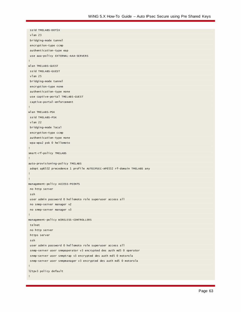
WiNG 5.X How-To Guide – Auto IPsec Secure using Pre Shared Keys
Page 63
ssid TMELABS-DOT1X
vlan 23
bridging-mode tunnel
encryption-type ccmp
authentication-type eap
use aaa-policy EXTERNAL-AAA-SERVERS
!
wlan TMELABS-GUEST
ssid TMELABS-GUEST
vlan 25
bridging-mode tunnel
encryption-type none
authentication-type none
use captive-portal TMELABS-GUEST
captive-portal-enforcement
!
wlan TMELABS-PSK
ssid TMELABS-PSK
vlan 22
bridging-mode local
encryption-type ccmp
authentication-type none
wpa-wpa2 psk 0 hellomoto
!
smart-rf-policy TMELABS
!
auto-provisioning-policy TMELABS
adopt ap6532 precedence 1 profile AUTOIPSEC-AP6532 rf-domain TMELABS any
!
!
management-policy ACCESS-POINTS
no http server
ssh
user admin password 0 hellomoto role superuser access all
no snmp-server manager v2
no snmp-server manager v3
!
management-policy WIRELESS-CONTROLLERS
telnet
no http server
https server
ssh
user admin password 0 hellomoto role superuser access all
snmp-server user snmpoperator v3 encrypted des auth md5 0 operator
snmp-server user snmptrap v3 encrypted des auth md5 0 motorola
snmp-server user snmpmanager v3 encrypted des auth md5 0 motorola
!
l2tpv3 policy default
!
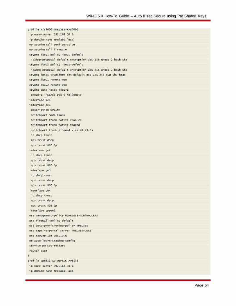
WiNG 5.X How-To Guide – Auto IPsec Secure using Pre Shared Keys
Page 64
profile rfs7000 TMELABS-RFS7000
ip name-server 192.168.10.6
ip domain-name tmelabs.local
no autoinstall configuration
no autoinstall firmware
crypto ikev1 policy ikev1-default
isakmp-proposal default encryption aes-256 group 2 hash sha
crypto ikev2 policy ikev2-default
isakmp-proposal default encryption aes-256 group 2 hash sha
crypto ipsec transform-set default esp-aes-256 esp-sha-hmac
crypto ikev1 remote-vpn
crypto ikev2 remote-vpn
crypto auto-ipsec-secure
groupid TMELABS psk 0 hellomoto
interface me1
interface ge1
description UPLINK
switchport mode trunk
switchport trunk native vlan 20
switchport trunk native tagged
switchport trunk allowed vlan 20,23-25
ip dhcp trust
qos trust dscp
qos trust 802.1p
interface ge2
ip dhcp trust
qos trust dscp
qos trust 802.1p
interface ge3
ip dhcp trust
qos trust dscp
qos trust 802.1p
interface ge4
ip dhcp trust
qos trust dscp
qos trust 802.1p
interface pppoe1
use management-policy WIRELESS-CONTROLLERS
use firewall-policy default
use auto-provisioning-policy TMELABS
use captive-portal server TMELABS-GUEST
ntp server 192.168.10.6
no auto-learn-staging-config
service pm sys-restart
router ospf
!
profile ap6532 AUTOIPSEC-AP6532
ip name-server 192.168.10.6
ip domain-name tmelabs.local

WiNG 5.X How-To Guide – Auto IPsec Secure using Pre Shared Keys
Page 65
no autoinstall configuration
no autoinstall firmware
crypto ikev1 policy ikev1-default
isakmp-proposal default encryption aes-256 group 2 hash sha
crypto ikev2 policy ikev2-default
isakmp-proposal default encryption aes-256 group 2 hash sha
crypto ipsec transform-set default esp-aes-256 esp-sha-hmac
crypto ikev1 remote-vpn
crypto ikev2 remote-vpn
crypto auto-ipsec-secure
groupid TMELABS psk 0 hellomoto
crypto load-management
interface radio1
wlan TMELABS-DOT1X bss 1 primary
wlan TMELABS-PSK bss 2 primary
wlan TMELABS-GUEST bss 3 primary
interface radio2
wlan TMELABS-DOT1X bss 1 primary
interface ge1
switchport mode trunk
switchport trunk native vlan 21
no switchport trunk native tagged
switchport trunk allowed vlan 21-22
ip dhcp trust
qos trust dscp
qos trust 802.1p
interface vlan21
ip address dhcp
ip dhcp client request options all
interface pppoe1
use management-policy ACCESS-POINTS
use firewall-policy default
ntp server 192.168.10.6
controller host 192.168.20.24 ipsec-secure gw 76.7.100.20
controller host 192.168.20.25 ipsec-secure gw 76.7.100.21
service pm sys-restart
router ospf
!
rf-domain TMELABS
location JohnsonCityTN
contact [email protected]
timezone EST5EDT
country-code us
use smart-rf-policy TMELABS
!
rf-domain default
no country-code
!
rfs7000 00-15-70-38-01-FD
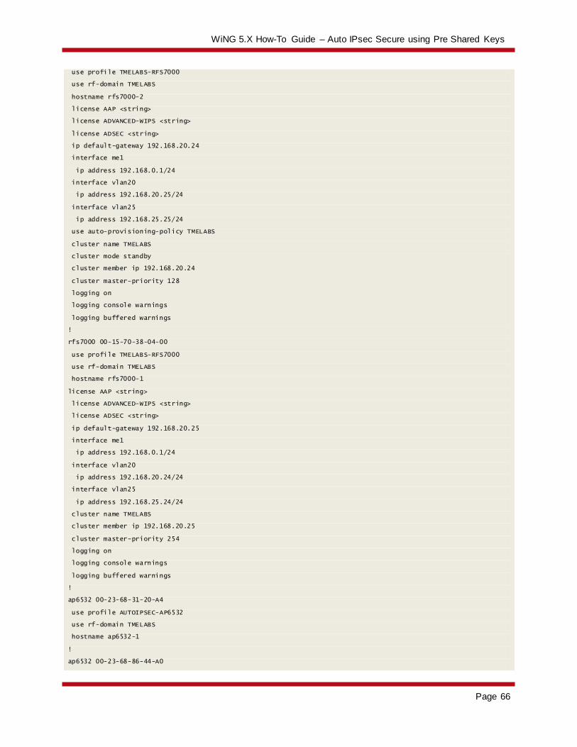
WiNG 5.X How-To Guide – Auto IPsec Secure using Pre Shared Keys
Page 66
use profile TMELABS-RFS7000
use rf-domain TMELABS
hostname rfs7000-2
license AAP <string>
license ADVANCED-WIPS <string>
license ADSEC <string>
ip default-gateway 192.168.20.24
interface me1
ip address 192.168.0.1/24
interface vlan20
ip address 192.168.20.25/24
interface vlan25
ip address 192.168.25.25/24
use auto-provisioning-policy TMELABS
cluster name TMELABS
cluster mode standby
cluster member ip 192.168.20.24
cluster master-priority 128
logging on
logging console warnings
logging buffered warnings
!
rfs7000 00-15-70-38-04-00
use profile TMELABS-RFS7000
use rf-domain TMELABS
hostname rfs7000-1
license AAP <string>
license ADVANCED-WIPS <string>
license ADSEC <string>
ip default-gateway 192.168.20.25
interface me1
ip address 192.168.0.1/24
interface vlan20
ip address 192.168.20.24/24
interface vlan25
ip address 192.168.25.24/24
cluster name TMELABS
cluster member ip 192.168.20.25
cluster master-priority 254
logging on
logging console warnings
logging buffered warnings
!
ap6532 00-23-68-31-20-A4
use profile AUTOIPSEC-AP6532
use rf-domain TMELABS
hostname ap6532-1
!
ap6532 00-23-68-86-44-A0

WiNG 5.X How-To Guide – Auto IPsec Secure using Pre Shared Keys
Page 67
use profile AUTOIPSEC-AP6532
use rf-domain TMELABS
hostname ap6532-2
!
ap6532 5C-0E-8B-33-EE-70
use profile AUTOIPSEC-AP6532
use rf-domain TMELABS
hostname ap6532-3
!
ap6532 5C-0E-8B-A4-48-80
use profile AUTOIPSEC-AP6532
use rf-domain TMELABS
hostname ap6532-4
!
ap6532 5C-0E-8B-A4-4B-48
use profile AUTOIPSEC-AP6532
use rf-domain TMELABS
hostname ap6532-5
!
ap6532 5C-0E-8B-A4-4C-3C
use profile AUTOIPSEC-AP6532
use rf-domain TMELABS
hostname ap6532-6
!
!
end
NAT / Firewalls (RFS4000)
!
! Configuration of RFS4000 version 5.3.1-009R
!
!
version 2.1
!
!
ip access-list INTERNET
permit udp any eq 500 any rule-precedence 10
permit udp any eq 4500 any rule-precedence 20
deny ip any any log rule-precedence 100
!
ip access-list NAT
permit ip 192.168.20.0/24 any rule-precedence 10
!
firewall-policy default
no ip dos tcp-sequence-past-window
!
!

WiNG 5.X How-To Guide – Auto IPsec Secure using Pre Shared Keys
Page 68
!
wlan-qos-policy default
qos trust dscp
qos trust wmm
!
radio-qos-policy default
!
ap300 default-ap300
interface radio1
interface radio2
!
!
management-policy default
no http server
https server
ssh
user admin password 0 hellomoto role superuser access all
no snmp-server manager v2
no snmp-server manager v3
!
l2tpv3 policy default
!
profile rfs4000 default-rfs4000
no mint mlcp vlan
no mint mlcp ip
autoinstall configuration
autoinstall firmware
crypto ikev1 policy ikev1-default
isakmp-proposal default encryption aes-256 group 2 hash sha
crypto ikev2 policy ikev2-default
isakmp-proposal default encryption aes-256 group 2 hash sha
crypto ipsec transform-set default esp-aes-256 esp-sha-hmac
crypto ikev1 remote-vpn
crypto ikev2 remote-vpn
crypto auto-ipsec-secure
interface radio1
interface radio2
interface up1
switchport mode trunk
switchport trunk native vlan 20
switchport trunk native tagged
switchport trunk allowed vlan 20
ip dhcp trust
qos trust dscp
qos trust 802.1p
interface ge5
switchport mode access
switchport access vlan 4094
ip dhcp trust

WiNG 5.X How-To Guide – Auto IPsec Secure using Pre Shared Keys
Page 69
qos trust dscp
qos trust 802.1p
interface wwan1
interface pppoe1
use firewall-policy default
logging on
service pm sys-restart
router ospf
!
rf-domain default
no country-code
!
rfs4000 00-23-68-22-9D-E4
use profile default-rfs4000
use rf-domain default
hostname NAT-GW-1
license AP DEFAULT-6AP-LICENSE
ip default-gateway 76.7.100.1
interface vlan20
description PRIVATE
ip address 192.168.20.20/24
ip nat inside
interface vlan4094
description PUBLIC
ip address 76.7.100.20/24
use ip-access-list in INTERNET
ip nat outside
cluster name NAT
cluster member ip 192.168.20.21
cluster master-priority 254
logging on
logging console warnings
logging buffered warnings
!
rfs4000 5C-0E-8B-1A-FE-A0
use profile default-rfs4000
use rf-domain default
hostname NAT-GW-2
license AP DEFAULT-6AP-LICENSE
ip default-gateway 76.7.100.1
interface vlan20
description PRIVATE
ip address 192.168.20.21/24
ip nat inside
interface vlan4094
description PUBLIC
ip address 76.7.100.21/24
use ip-access-list in INTERNET
ip nat outside

WiNG 5.X How-To Guide – Auto IPsec Secure using Pre Shared Keys
Page 70
cluster name NAT
cluster member ip 192.168.20.20
logging on
logging console warnings
logging buffered warnings
ip nat outside destination static 76.7.100.21 4500 udp 192.168.20.25 4500
ip nat outside destination static 76.7.100.21 500 udp 192.168.20.25 500
ip nat inside source list NAT interface vlan4094 overload
!
!
end

WiNG 5.X How-To Guide – Auto IPsec Secure using Pre Shared Keys
Page 71
4.1.3 Public Network Deployments with VPN Gateways
RFS7000 Controllers
!### show running-config
!
! Configuration of RFS7000 version 5.3.1.0-009R
!
!
version 2.1
!
!
ip access-list BROADCAST-MULTICAST-CONTROL
permit tcp any any rule-precedence 10 rule-description "permit all TCP traffic"
permit udp any eq 67 any eq dhcpc rule-precedence 11 rule-description "permit DHCP replies"
deny udp any range 137 138 any range 137 138 rule-precedence 20 rule-description "deny windows netbios"
deny ip any 224.0.0.0/4 rule-precedence 21 rule-description "deny IP multicast"
deny ip any host 255.255.255.255 rule-precedence 22 rule-description "deny IP local broadcast"
permit ip any any rule-precedence 100 rule-description "permit all IP traffic"
!
mac access-list PERMIT-ARP-AND-IPv4
permit any any type ip rule-precedence 10 rule-description "permit all IPv4 traffic"
permit any any type arp rule-precedence 20 rule-description "permit all ARP traffic"
!
firewall-policy default
no ip dos tcp-sequence-past-window
!
!
mint-policy global-default
!
wlan-qos-policy default
qos trust dscp
qos trust wmm
!
radio-qos-policy default
!
aaa-policy EXTERNAL-AAA-SERVERS
authentication server 1 host 192.168.10.6 secret 0 hellomoto
authentication server 1 proxy-mode through-controller
!
captive-portal TMELABS-GUEST
server host portal.tmelabs.local
server mode centralized-controller
webpage internal org-name Motorola Solutions
webpage internal org-signature © 2012 Motorola Solutions. All Rights Reserved.
use aaa-policy EXTERNAL-AAA-SERVERS
!
wlan TMELABS-DOT1X

WiNG 5.X How-To Guide – Auto IPsec Secure using Pre Shared Keys
Page 72
ssid TMELABS-DOT1X
vlan 23
bridging-mode tunnel
encryption-type ccmp
authentication-type eap
use aaa-policy EXTERNAL-AAA-SERVERS
!
wlan TMELABS-GUEST
ssid TMELABS-GUEST
vlan 25
bridging-mode tunnel
encryption-type none
authentication-type none
use captive-portal TMELABS-GUEST
captive-portal-enforcement
!
wlan TMELABS-PSK
ssid TMELABS-PSK
vlan 22
bridging-mode local
encryption-type ccmp
authentication-type none
wpa-wpa2 psk 0 hellomoto
!
smart-rf-policy TMELABS
!
auto-provisioning-policy TMELABS
adopt ap6532 precedence 1 profile AUTOIPSEC-AP6532 rf-domain TMELABS any
!
!
management-policy ACCESS-POINTS
no http server
ssh
user admin password 0 hellomoto role superuser access all
no snmp-server manager v2
no snmp-server manager v3
!
management-policy WIRELESS-CONTROLLERS
telnet
no http server
https server
ssh
user admin password 0 hellomoto role superuser access all
snmp-server user snmpoperator v3 encrypted des auth md5 0 operator
snmp-server user snmptrap v3 encrypted des auth md5 0 motorola
snmp-server user snmpmanager v3 encrypted des auth md5 0 motorola
!
l2tpv3 policy default
!

WiNG 5.X How-To Guide – Auto IPsec Secure using Pre Shared Keys
Page 73
profile rfs7000 TMELABS-RFS7000
ip name-server 192.168.10.6
ip domain-name tmelabs.local
no autoinstall configuration
no autoinstall firmware
crypto ikev1 policy ikev1-default
isakmp-proposal default encryption aes-256 group 2 hash sha
crypto ikev2 policy ikev2-default
isakmp-proposal default encryption aes-256 group 2 hash sha
crypto ipsec transform-set default esp-aes-256 esp-sha-hmac
crypto ikev1 remote-vpn
crypto ikev2 remote-vpn
interface me1
interface ge1
description UPLINK
switchport mode trunk
switchport trunk native vlan 20
switchport trunk native tagged
switchport trunk allowed vlan 20,23-25
ip dhcp trust
qos trust dscp
qos trust 802.1p
interface ge2
ip dhcp trust
qos trust dscp
qos trust 802.1p
interface ge3
ip dhcp trust
qos trust dscp
qos trust 802.1p
interface ge4
ip dhcp trust
qos trust dscp
qos trust 802.1p
interface pppoe1
use management-policy WIRELESS-CONTROLLERS
use firewall-policy default
use auto-provisioning-policy TMELABS
use captive-portal server TMELABS-GUEST
ntp server 192.168.10.6
no auto-learn-staging-config
service pm sys-restart
router ospf
!
profile ap6532 AUTOIPSEC-AP6532
ip name-server 192.168.10.6
ip domain-name tmelabs.local
no autoinstall configuration
no autoinstall firmware

WiNG 5.X How-To Guide – Auto IPsec Secure using Pre Shared Keys
Page 74
crypto ikev1 policy ikev1-default
isakmp-proposal default encryption aes-256 group 2 hash sha
crypto ikev2 policy ikev2-default
isakmp-proposal default encryption aes-256 group 2 hash sha
crypto ipsec transform-set default esp-aes-256 esp-sha-hmac
crypto ikev1 remote-vpn
crypto ikev2 remote-vpn
crypto auto-ipsec-secure
groupid TMELABS psk 0 hellomoto
crypto load-management
interface radio1
wlan TMELABS-DOT1X bss 1 primary
wlan TMELABS-PSK bss 2 primary
wlan TMELABS-GUEST bss 3 primary
interface radio2
wlan TMELABS-DOT1X bss 1 primary
interface ge1
switchport mode trunk
switchport trunk native vlan 21
no switchport trunk native tagged
switchport trunk allowed vlan 21-22
ip dhcp trust
qos trust dscp
qos trust 802.1p
interface vlan21
ip address dhcp
ip dhcp client request options all
interface pppoe1
use management-policy ACCESS-POINTS
use firewall-policy default
ntp server 192.168.10.6
controller host 192.168.20.24 ipsec-secure gw 76.7.100.20
controller host 192.168.20.25 ipsec-secure gw 76.7.100.21
service pm sys-restart
router ospf
!
rf-domain TMELABS
location JohnsonCityTN
contact [email protected]
timezone EST5EDT
country-code us
use smart-rf-policy TMELABS
!
rf-domain default
no country-code
!
rfs7000 00-15-70-38-01-FD
use profile TMELABS-RFS7000
use rf-domain TMELABS

WiNG 5.X How-To Guide – Auto IPsec Secure using Pre Shared Keys
Page 75
hostname rfs7000-2
license AAP <string>
license ADVANCED-WIPS <string>
license ADSEC <string>
ip default-gateway 192.168.20.24
interface me1
ip address 192.168.0.1/24
interface vlan20
ip address 192.168.20.25/24
interface vlan25
ip address 192.168.25.25/24
use auto-provisioning-policy TMELABS
cluster name TMELABS
cluster mode standby
cluster member ip 192.168.20.24
cluster master-priority 128
logging on
logging console warnings
logging buffered warnings
!
rfs7000 00-15-70-38-04-00
use profile TMELABS-RFS7000
use rf-domain TMELABS
hostname rfs7000-1
license AAP <string>
license ADVANCED-WIPS <string>
license ADSEC <string>
ip default-gateway 192.168.20.25
interface me1
ip address 192.168.0.1/24
interface vlan20
ip address 192.168.20.24/24
interface vlan25
ip address 192.168.25.24/24
cluster name TMELABS
cluster member ip 192.168.20.25
cluster master-priority 254
logging on
logging console warnings
logging buffered warnings
!
ap6532 00-23-68-31-20-A4
use profile AUTOIPSEC-AP6532
use rf-domain TMELABS
hostname ap6532-1
!
ap6532 00-23-68-86-44-A0
use profile AUTOIPSEC-AP6532
use rf-domain TMELABS
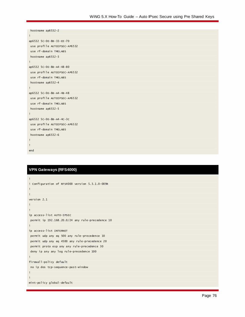
WiNG 5.X How-To Guide – Auto IPsec Secure using Pre Shared Keys
Page 76
hostname ap6532-2
!
ap6532 5C-0E-8B-33-EE-70
use profile AUTOIPSEC-AP6532
use rf-domain TMELABS
hostname ap6532-3
!
ap6532 5C-0E-8B-A4-48-80
use profile AUTOIPSEC-AP6532
use rf-domain TMELABS
hostname ap6532-4
!
ap6532 5C-0E-8B-A4-4B-48
use profile AUTOIPSEC-AP6532
use rf-domain TMELABS
hostname ap6532-5
!
ap6532 5C-0E-8B-A4-4C-3C
use profile AUTOIPSEC-AP6532
use rf-domain TMELABS
hostname ap6532-6
!
!
end
VPN Gateways (RFS4000)
!
! Configuration of RFS4000 version 5.3.1.0-009R
!
!
version 2.1
!
!
ip access-list AUTO-IPSEC
permit ip 192.168.20.0/24 any rule-precedence 10
!
ip access-list INTERNET
permit udp any eq 500 any rule-precedence 10
permit udp any eq 4500 any rule-precedence 20
permit proto esp any any rule-precedence 30
deny ip any any log rule-precedence 100
!
firewall-policy default
no ip dos tcp-sequence-past-window
!
!
mint-policy global-default

WiNG 5.X How-To Guide – Auto IPsec Secure using Pre Shared Keys
Page 77
!
meshpoint-qos-policy default
!
wlan-qos-policy default
qos trust dscp
qos trust wmm
!
radio-qos-policy default
!
ap300 default-ap300
interface radio1
interface radio2
!
!
management-policy default
no http server
https server
ssh
user admin password 0 hellomoto role superuser access all
no snmp-server manager v2
no snmp-server manager v3
!
l2tpv3 policy default
!
profile rfs4000 default-rfs4000
no mint mlcp vlan
no mint mlcp ip
autoinstall configuration
autoinstall firmware
crypto ikev1 policy ikev1-default
isakmp-proposal default encryption aes-256 group 2 hash sha
crypto ikev2 policy ikev2-default
isakmp-proposal default encryption aes-256 group 2 hash sha
isakmp-proposal auto-tunnel-gw encryption aes-256 group 2 hash sha
crypto ikev2 peer AUTO-IPSEC
ip address 0.0.0.0
remoteid string TMELABS
localid string TMELABS
authentication psk 0 hellomoto local
authentication psk 0 hellomoto remote
crypto ipsec transform-set default esp-aes-256 esp-sha-hmac
crypto map AUTO-IPSEC 1 ipsec-isakmp
use ip-access-list AUTO-IPSEC
peer 1 ikev2 AUTO-IPSEC
crypto ikev1 remote-vpn
crypto ikev2 remote-vpn
crypto auto-ipsec-secure
interface radio1
interface radio2

WiNG 5.X How-To Guide – Auto IPsec Secure using Pre Shared Keys
Page 78
interface up1
switchport mode trunk
switchport trunk native vlan 20
switchport trunk native tagged
switchport trunk allowed vlan 20
ip dhcp trust
qos trust dscp
qos trust 802.1p
interface ge5
switchport mode access
switchport access vlan 4094
ip dhcp trust
qos trust dscp
qos trust 802.1p
interface wwan1
interface pppoe1
use dhcp-server-policy default
use firewall-policy default
logging on
service pm sys-restart
router ospf
!
rf-domain default
no country-code
!
rfs4000 00-23-68-22-9D-E4
use profile default-rfs4000
use rf-domain default
hostname VPN-GW-1
license AP DEFAULT-6AP-LICENSE
ip default-gateway 76.7.100.1
interface vlan20
description PRIVATE
ip address 192.168.20.20/24
interface vlan4094
description PUBLIC
ip address 76.7.100.20/24
use ip-access-list in INTERNET
crypto map AUTO-IPSEC
cluster name IPSEC-GW
cluster member ip 192.168.20.21
cluster master-priority 254
logging on
logging console warnings
logging buffered warnings
!
rfs4000 5C-0E-8B-1A-FE-A0
use profile default-rfs4000
use rf-domain default
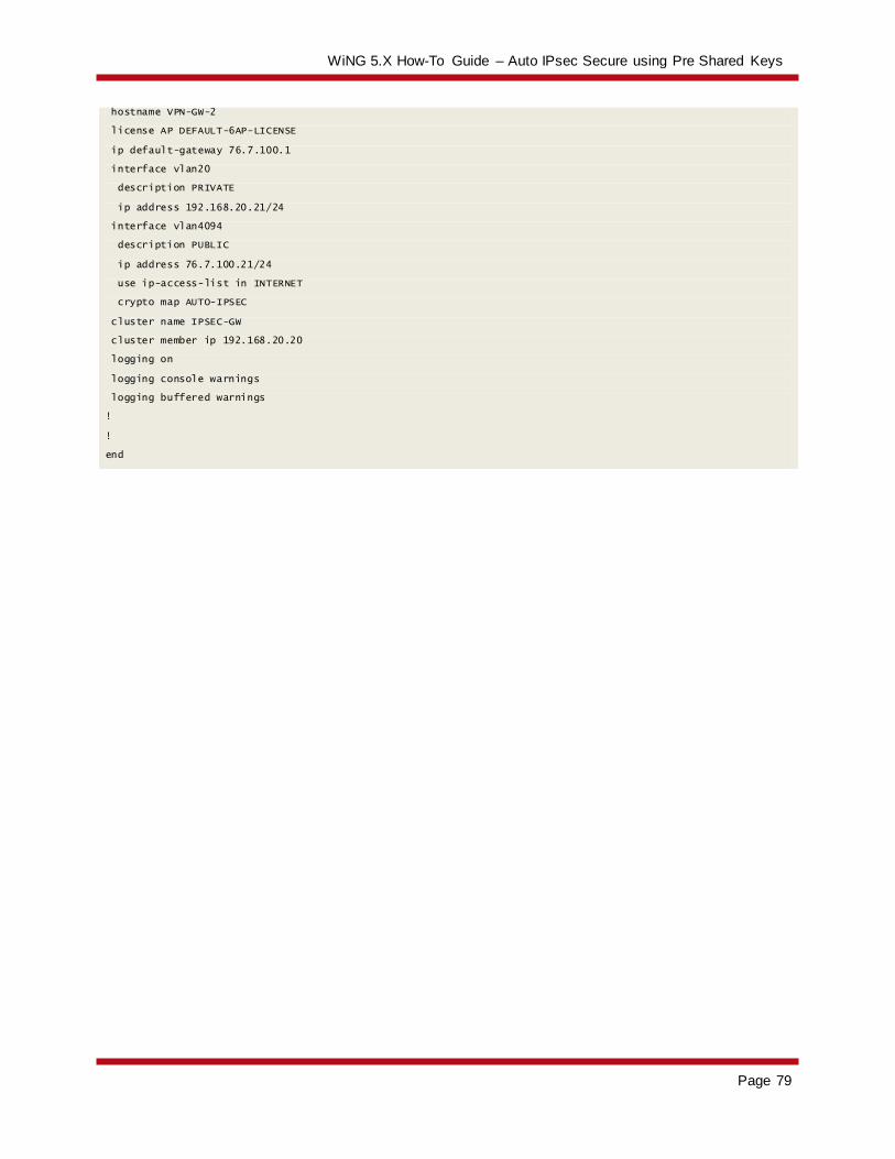
WiNG 5.X How-To Guide – Auto IPsec Secure using Pre Shared Keys
Page 79
hostname VPN-GW-2
license AP DEFAULT-6AP-LICENSE
ip default-gateway 76.7.100.1
interface vlan20
description PRIVATE
ip address 192.168.20.21/24
interface vlan4094
description PUBLIC
ip address 76.7.100.21/24
use ip-access-list in INTERNET
crypto map AUTO-IPSEC
cluster name IPSEC-GW
cluster member ip 192.168.20.20
logging on
logging console warnings
logging buffered warnings
!
!
end

WiNG 5.X How-To Guide – Auto IPsec Secure using Pre Shared Keys
Page 80


![Rachmaninov 3rd Piano Concerto [First Movement] · PDF file53-g e5 = 5 !5 = 5 5 5 5 5 4 5 5 =5 5 = 5e5 5 5 5 5 5 5 5e5 5 5!55 5 5 5 5 5e5 5 5 5 5 5 5! 5 $3e55 5 5: 5 5 5 55 5e 55 5](https://static.fdocuments.us/doc/165x107/5a78944a7f8b9a1f128d15db/rachmaninov-3rd-piano-concerto-first-movement-53-g-e5-5-5-5-5-5-5-5-4-5.jpg)


