WINEGARD - Argo RV
16
Winegard Company • 3000 Kirkwood St. • Burlington, IA 52601-2000 319/754-0600 • FAX 319/754-0787 • www.winegard.com Printed in U.S.A. © Winegard Company 2008 2452133 WINEGARD ® TRAV’LER TM Automatic Multi-Satellite TV Antenna Model SK-3005 DIRECTV ® SLIMLINE INSTALLATION MANUAL Made in the U.S.A. SK-3005
Transcript of WINEGARD - Argo RV

Winegard Company • 3000 Kirkwood St. • Burlington, IA 52601-2000319/754-0600 • FAX 319/754-0787 • www.winegard.comPrinted in U.S.A. © Winegard Company 2008 2452133
WINEGARD®
TRAV’LERTM
Automatic Multi-Satellite TV Antenna
Model SK-3005 DIRECTV® SLIMLINE
INSTALLATION MANUALMade in the U.S.A.
SK-3005

Congratulations!
You have selected the Winegard® TRAV’LER Automatic Multi-Satellite TV Antenna. The TRAV’LER antenna will deliver the ability to view up to five satellites at the same time with unmatched signal strength, the lowest travel height on the market, maximum HD capabilities and easy to use functionality – just like you get at home. This manual provides important information on the installation and operation of your TRAV’LER Interface Box. Please take time to read the manual in it’s entirety before installing or operating your antenna.
Recommended Receivers:
The Winegard® TRAV’LER Automatic Multi-Satellite TV Antenna will work with any DIRECTV® receiver currently in production. Consult your receiver manual or www.winegard.com if you have any questions about whether your receiver is compatible. However, we recommend:
DIRECTV : models D11 and H20
Each receiver will require at least one coax cable. Refer to receiver manual for wiring details.
Check with your programming provider for coverage in certain areas.
Before you begin, please make sure you have received all necessary parts to properly install and oper-ate your TRAV’LER antenna. - Installation/Operation Manual - Mount Base with 30’ Cable - Power/Control Cable - TRAV’LER Interface Box - Reflector, LNBF & Feed Arm - 24” AC power cord - TRAV’LER Power supply - Gray Coax Cable 30’ - Black Coax Cable 30’ - Mounting Hardware bag - Cable Entry Hardware bag
Selecting a Location for the TRAV’LER Antenna
Before removing the TRAV’LER antenna from its box, check with your RV Dealer or manufacturer. Your RV may be pre-wired or have a reinforced area for this system. DO NOT install in a location where a gap of 3/16” or more exists, as it may damage the roof. See diagram at top of page 3.
2
Icons appearing in the manual are used for important information and helpful tips. Alert indicates important information regarding product use, product specifications or procedures.
Important tip offers helpful suggestions or refers you to a related topic in the manual.
INSTALLATION

Once you have checked for this:1. Choose a location on the roof of the RV that will allow the dish to raise and rotate without interfer-ence from other roof mounted equipment. The TRAV’LER antenna may only be mounted parallel to the centerline of the coach.
2. The minimum roof space required for the TRAV’LER antenna is 44” L x 34” W. a. The operational space requires that no obstructions taller than 8 inches be mounted within a 68” diameter circle from the center of the unit.
FIGURE 2
3
Mount Parallel to Center Line of Coach
FRO
NT O
F RV
You must find a location on the roof that provides adequate space to allow the TRAV’LER antenna to operate. The TRAV’LER antenna has a Front and Back and must be mounted correctly to avoid dam-age to the TRAV’LER antenna or the coach. The antenna must be mounted +/-3 degrees of level or the system may not function correctly. The Transition plate for the TRAV’LER unit is marked “FRONT” and “BACK”. See Figure 1.
FIGURE 1
FRO
NT O
F RV
TRANSITION PLATE
Mount Parallel to Center Line of Coach!
Winegard is NOT liable for dam-age, expenses, or injury caused by improper installation.
3/16”Plan your entire installation before you start. Determine the location of all of your equipment and make sure cable and wires are long enough to reach their destination points.
FRO
NT
BA
CK
INSTALLATION

NOTE: Anything in the striped area will interfere with the operation of the TRAV’LER antenna and may cause damage to the object or the TRAV’LER antenna.
TRAV’LER Mount Installation
Verify that the “FRONT” of the transition plate is facing the front of the vehicle, then place the TRAV’LER antenna mount on the roof where you plan to install it. See Figure 3. Mark where the screw holes will go by placing marks through the holes in the mount base on the roof of the RV. It is impor-tant that you be able to see these marks! Move the TRAV’LER mount out of the installation area. It is recommended that you don’t pre-drill the holes at this time.
Use a solid bead of sealant to connect these marks in the shape of the base.
Replace the TRAV’LER antenna base and screw it to the roof. Check with your vehicle manufacturer for any special screw requirements before using the supplied screws.
3. The unit must be within 3° of level for best operation.4. Make sure that the location offers enough support to attach the TRAV’LER antenna securely.5. Find a well ventilated location with a 110 V outlet for the TRAV’LER Interface inside the vehicle.
Make sure to clean the installation area before you begin.
You will want to decide where the wires will enter the vehicle. One coax cable per receiver and a control cable will need to be run into the vehicle.
Warning: Do not run the wires through the striped area shown. Consult your receiver manual for specifics in the diagram.
FIGURE 3
4
!
INSTALLATION
FRO
NT O
F RV
TRANSITION PLATE
FRO
NT
SCREW HOLES
24 inches
18 inches
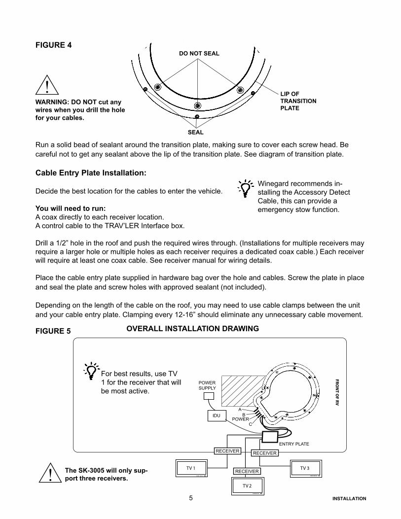
Run a solid bead of sealant around the transition plate, making sure to cover each screw head. Be careful not to get any sealant above the lip of the transition plate. See diagram of transition plate.
Cable Entry Plate Installation:
Decide the best location for the cables to enter the vehicle. You will need to run:A coax directly to each receiver location.A control cable to the TRAV’LER Interface box.
Drill a 1/2” hole in the roof and push the required wires through. (Installations for multiple receivers may require a larger hole or multiple holes as each receiver requires a dedicated coax cable.) Each receiver will require at least one coax cable. See receiver manual for wiring details.
Place the cable entry plate supplied in hardware bag over the hole and cables. Screw the plate in place and seal the plate and screw holes with approved sealant (not included).
Depending on the length of the cable on the roof, you may need to use cable clamps between the unit and your cable entry plate. Clamping every 12-16” should eliminate any unnecessary cable movement.
FIGURE 4
LIP OF TRANSITION PLATE
DO NOT SEAL
SEAL
2
FIGURE 5 OVERALL INSTALLATION DRAWING
!WARNING: DO NOT cut any wires when you drill the hole for your cables.
5
TV
FRO
NT O
F RV
TV 1 TV 3
IDUA
BPOWER
C
POWERSUPPLY
For best results, use TV 1 for the receiver that will be most active.
ENTRY PLATE
Winegard recommends in-stalling the Accessory Detect Cable, this can provide a emergency stow function.
! The SK-3005 will only sup-port three receivers.
INSTALLATION
RECEIVER
RECEIVER
RECEIVER

Cable installation:Connect the control cable and power cable to the back of the TRAV’LER Interface box as shown below. Note: For cable runs longer than 25’ an extension may be purchased. Do not exceed 50’ of cable.
Attach the TRAV’LER control cable to the TRAV’LER Interface Box, as shown in Figure 5.Attach the output cable from the Power supply to the TRAV’LER Interface Box. See above. Finally, connect a coax cable from the TRAV’LER mount to each of the receivers being used with the TRAV’LER Automatic Satellite Dish. See Appendix for information on properly installing a Hex Connector.
Find a location to plug in the TRAV’LER Power supply and plug it in.
Reflector Installation:Once the wires are run and the sealant has started to cure:Check to be sure that there is nothing above the TRAV’LER that might prevent it from raising. You will need at least 40” of clearance above the TRAV’LER Mount to ensure that you have room to install the reflector.
Steps 1-7 explain how to use the TRAV’LER Interface box to raise the mount to install the reflector.
1. Press [POWER] and hold for 2 seconds to turn “ON” the TRAV’LER Interface Box. Wait until the Interface Box finishes “connecting to antenna”.TIP: You have “10 SECONDS” to do Step 2 or the “Search Routine” starts. (See NOTE)
2. Press [ENTER] and hold for 2 seconds or until the unit displays “Enter User Menu”. Press [SELECT] to move the asterisk to “Yes”. Press [ENTER].
3. Press [SELECT] to move the asterisk to [INSTALLATION].
4. Press [ENTER]. You will be asked to provide a code to enter the Installation Menu.
5. Press [ENTER] 4 times to enter code 0000.
6. Press [SELECT] to move the asterisk to [RAISE DISH]. Press [ENTER]. Press [SELECT] to move the asterisk to “Yes”.
7. Press [ENTER]. The TRAV’LER mount will raise up about half way, to make it possible to attach the reflector.
NOTE: If the TRAV’LER enters the “Search Routine” you can still enter the “Menu Mode”. See steps A & B.
If the TRAV’LER Mount raises past 1/2 way before [RAISE DISH] is selected (See Step 6), the TRAV’LER will hit its Upper Hard Stop and “Motor Stall” appears. This is Normal!
The “Motor Stall” means the TRAV’LER is all the way up & the mount can raise no more. There are two easy ways to clear the “Motor Stall”. Either is okay. (See Steps A & B).
FIGURE 5 PowerControl Cable
``
6
FIGURE 5
INSTALLATION
Receiver Setup:
If you are not able to see all of your channels or the receiver displays an error, it may be necessary to go through the receiver set up once the TRAV’LER has finished a successful search.
Please refer to your Receiver Manual to enter the Guided Setup, using five LNB Multi-Sat for antenna type.
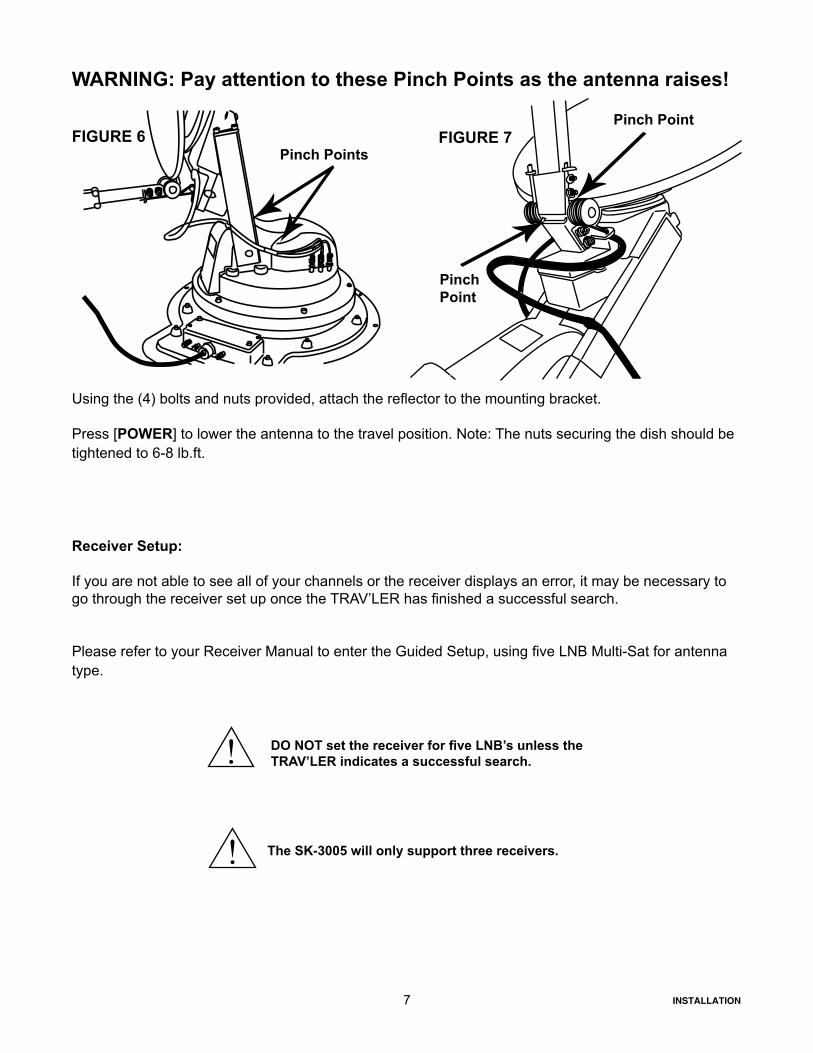
WARNING: Pay attention to these Pinch Points as the antenna raises!
Using the (4) bolts and nuts provided, attach the reflector to the mounting bracket.
Press [POWER] to lower the antenna to the travel position. Note: The nuts securing the dish should be tightened to 6-8 lb.ft.
FIGURE 6 FIGURE 7
7
Pinch Points
Pinch Point
Pinch Point
! DO NOT set the receiver for five LNB’s unless the TRAV’LER indicates a successful search.
! The SK-3005 will only support three receivers.
INSTALLATION

Appendix:
Making the Right Connection with FC-5910 Hex ConnectorsMaking a coaxial cable connection is critical. If you have the basic technique right you can modify it to your own personal taste. Whether you use a knife, stripping tool or diagonal cutter, the important thing is to make a good clean cut. A hex crimping tool is required for hex connectors, for maximum RF transmis-sion.As mentioned before, the choice of tools is yours. Be sure you do a precise job. Failure to do so can cost you time and money in trying to locate a system problem.
Cut the cable flush. Strip the outer jacket off 1/2”, then trim the dielectric by cutting partially thru. DO NOT NICK THE CENTER CONDUCTOR! Twist and pull off leaving a 1/2” minu-mum of exposed center conductor.
Remove additional 1/4” of the outer jacket.Pull the braid away from the dielectric and fold over the jacket. If there’s any residue on the center conductor scrape off with non-metallic object.
Slide FC -5910 connector onto coax. Trim off excess braid.
Look into end of connector to make sure no braid or aluminum foil touches or has the possibility of touching the center conductor. Shorting can result if either comes in contact with center conductor. Close crimping tool making correct crimp.
IN HOT WEATHER: Trim off center conductor leaving 3/16” beyond the connector. The center conductor expands at higher temperatures. If a little extra is not provided, it may contract enough in the winter to cre-ate an open connection and result in loss of picture.
IN COLD WEATHER OR INDOORS: Trim off center conductor leaving it extended 1/16” of an inch beyond the connector. (Use diagonal pliers for cutting center conductor).
8
! DO NOT paint this antenna! Painting the TRAV’LER antenna
will void your warranty.
INSTALLATION

9
WINEGARD MOBILE PRODUCTS LIMITED WARRANTY(2 YEARS PARTS; 1 YEAR LABOR)
Winegard Company warrants this product against defects in materials or workmanship for a period of two (2) years from the date of original purchase. During year one (1) of such warranty, Winegard Company will also pay authorized labor costs to an authorized Winegard dealer to repair or replace defective products. No warranty claim will be honored unless at the time the claim is made, Customer presents proof of purchase to an authorized Winegard dealer (to locate the nearest authorized Winegard dealer, contact Winegard Company, 3000 Kirkwood Street, Burlington, Iowa 52601, Telephone 319-754-0600 or visit www.winegard.com). Customer must provide proof of purchase with a dated sales receipt for the Winegard product to verify the product is under warranty. If the date of purchase cannot be verified, the warranty period shall be considered to begin thirty (30) days after the date of manufacture. If a defect in material or workmanship is discovered, Customer may take the product to an authorized Winegard dealer for service. Customer must provide proof of purchase to verify the product is under warranty. If the product is brought to an authorized Winegard dealer for service prior to expiration of year one (1) of the warranty period and a defect in material or workmanship is verified by Winegard Technical Services, Winegard Company will cover the Winegard dealer’s labor charges for warranty service. The Winegard dealer must contact Winegard Technical Services in advance for pre-approval of the service. Approval of the service is at the sole discretion of Winegard Company. Alternatively, Customer may ship the product prepaid to Winegard Technical Services (located at 3000 Kirkwood Street, Burlington, Iowa 52601, Telephone 319-754-0600). Customer must return the product along with a brief description of the problem and provide Winegard Technical Services with Customer’s name, address, and phone number. Customer must also provide proof of purchase to verify the product is under warranty. If the product is returned before the expiration of the warranty period, Winegard Company will (at its option) either repair or replace the product. This Limited Warranty does not apply if the product has been damaged, deteriorates, malfunctions or fails from: improper installation, misuse, abuse, neglect, accident, tampering, modification of the product as originally manufactured by Winegard in any manner whatsoever, removing or defacing any serial number, usage not in accordance with product instructions or acts of nature such as damage caused by wind, lightning, ice or corrosive environments such as salt spray and acid rain.
RETURN AUTHORIZATION POLICY A Return Material Authorization (RMA) is required prior to returning any product to Winegard Company or Winegard Warranty Services under this warranty policy. Please call our Technical Services Department at (800) 788-4417 or send an e-mail to [email protected] to obtain the RMA number. Please furnish the date of purchase when requesting an RMA number. Enclose the product in a prepaid package and write the RMA number in large, clear letters on the outside of the package. To avoid confusion or misunderstanding, a shipment(s) without an RMA number(s) or an unauthorized return(s) will be refused and returned to Customer freight collect. WINEGARD COMPANY DOES NOT ASSUME ANY LIABILITIES FOR ANY OTHER WARRANTIES, EXPRESS OR IMPLIED, MADE BY ANY OTHER PERSON. ALL OTHER WARRANTIES WHETHER EXPRESS, IMPLIED OR STATUTORY INCLUDING WARRANTIES OF FITNESS FOR A PARTICULAR PURPOSE AND MERCHANTABILITY ARE LIMITED TO THE TWO YEAR PERIOD OF THIS WARRANTY. In states that do not allow limitations on implied warranties, or the exclusion of limitation of incidental or consequential damages, the above limitations or exclusions do not apply. Some states do not allow limitations on how long an implied warranty lasts, or the exclusion of limitation of incidental or consequential damages, so the above limitations or exclusions may not apply to you. This warranty gives Customer specific legal rights. Customer may also have other rights that may vary from state to state.
SATELLITE RECEIVER WARRANTY: See manufacturer’s limited warranty policy.
INSTALLATION

TRAV’LERTM
Automatic Multi-Satellite TV Antenna
Model SK-3005 DIRECTV® SLIMLINE
OPERATION MANUALMade in the U.S.A.
Winegard Company • 3000 Kirkwood St. • Burlington, IA 52601-2000319/754-0600 • FAX 319/754-0787 • www.winegard.comPrinted in U.S.A. © Winegard Company 2007 2452133
WINEGARD®
SK-3005

Congratulations!
You have selected the Winegard® TRAV’LER Automatic Multi-Satellite TV Antenna. The TRAV’LER will deliver the ability to view up to five satellites at the same time with unmatched signal strength, the lowest travel height on the market, maximum HD capabilities and easy to use functionality – just like you get at home. This manual provides important information on the installation and operation of your TRAV’LER Interface Box. Please take time to read the manual in it’s entirety before installing or oper-ating your antenna.
Icons appearing in the manual are used for important information and helpful tips.
Alert indicates important information regarding product use, product specifications or procedures.
Important tip offers helpful suggestions or refers you to a related topic in the manual.
For Winegard Warranty Information:Att: Technical ServicesWinegard Company 3000 Kirkwood St.Burlington, IA 52601800-788-4417
DisclaimerAlthough every effort has been made to insure the information in this manual is correct and complete, no company shall be held liable for any errors or omissions in this manual. All information contained in this manual is subject to change without notice. No warranty of any kind is made with regard to the information included in this manual. The Satellite Interface is designed specifically for use with motorized recreational vehicles and information contained herein is provided for that purpose only.
Trademarks*WINEGARD and TRAV’LER are trademarks of Winegard Company. DISH Network is a registered trademark of EchoStar Satellite L.L.C. DIRECTV is a registered trademark of DIRECTV, Inc., a unit of Hughes Electronics Corp. ExpressVu is a registered trademark of Bell Canada, Inc. All trademarks contained in this manual are property of their respective owners. Reference made to products or services provided by companies, other than Winegard Company, does not represent any endorsement of those products or services.
2 OPERATION

OperationThe TRAV’LER Interface offers a simple one button operation that is also protected from accidental searches by a careful delay. Simply pressing the [Power] button will not start a search.
To start a search:
Press and Hold [Power] for two seconds or until the TRAV’LER interface displays “POWER ON”.
Now the power is ON, the button may be released.
Once the power is on, the TRAV’LER Interface will try to determine the type of dish that it is working with. The TRAV’LER Interface will display the type of satellite dish on the top line and the action it is taking on the bottom. See below.
The TRAV’LER antenna will enter the search mode as part of its normal operation. The first part of the search is for the TRAV’LER to find its “Home” position. Once it finds it home position, it will begin to look for a satellite.
When the TRAV’LER antenna finds a satellite, it will fine tune or “Peak” on the signal and determine which of the satellites it has found. Once the TRAV’LER knows which satellite it has found, it can move directly to the correct satellite(s).
The TRAV’LER antenna in its automatic search mode will lock onto three different satellites. As it finishes its search, the TRAV’LER will display an “ * ” for each of the satellites it found. See below.
WINEGARD COMPANY
POWER ON
CONNECTING
TO ANTENNA
DIRECTV SLIMLINE
READY MULTI-SAT
DIRECTV SLIMLINEHOME EL
DIRECTV SLIMLINE
HOME AZ/SK
3
DIRECTV SLIMLINE
*99 *101 *103 *110 *119
DIRECTV USERS
Now you are ready to watch TV.OPERATION
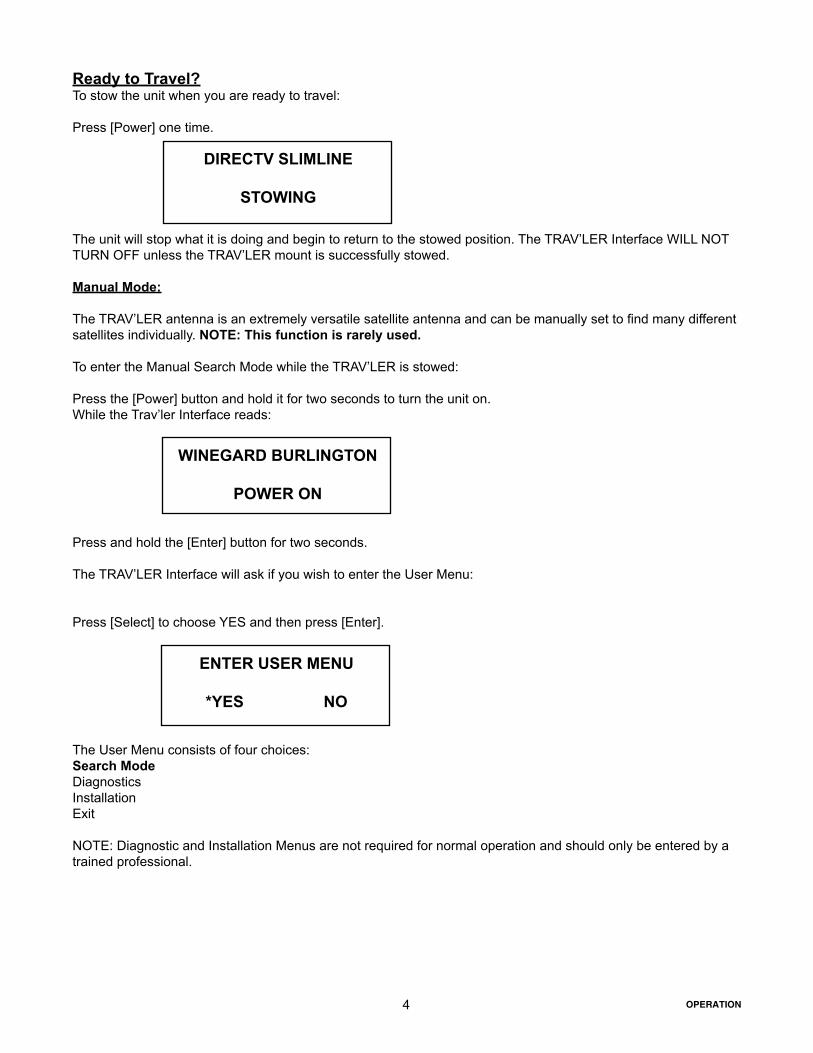
Ready to Travel?To stow the unit when you are ready to travel:
Press [Power] one time.
The unit will stop what it is doing and begin to return to the stowed position. The TRAV’LER Interface WILL NOT TURN OFF unless the TRAV’LER mount is successfully stowed.
Manual Mode:
The TRAV’LER antenna is an extremely versatile satellite antenna and can be manually set to find many different satellites individually. NOTE: This function is rarely used.
To enter the Manual Search Mode while the TRAV’LER is stowed:
Press the [Power] button and hold it for two seconds to turn the unit on.While the Trav’ler Interface reads:
Press and hold the [Enter] button for two seconds.
The TRAV’LER Interface will ask if you wish to enter the User Menu:
Press [Select] to choose YES and then press [Enter].
The User Menu consists of four choices:Search ModeDiagnosticsInstallationExit
NOTE: Diagnostic and Installation Menus are not required for normal operation and should only be entered by a trained professional.
DIRECTV SLIMLINE
STOWING
4
WINEGARD BURLINGTON
POWER ON
ENTER USER MENU
*YES NO
OPERATION

MANUAL 101MANUAL 110MANUAL 119MANUAL 129MANUAL 148MAIN MENU (returns to the User Menu)EXIT (Enters the Search Routine)
Press [Select] to cycle through each of these satellites until the asterisk is next to the satellite you wish to find. Then press [Enter].
The TRAV’LER Interface will ask you to confirm the change:
Press [Select] to move the asterisk to YES.
The Trav’ler Interface will acknowledge your selection and ask:
Pressing [Enter] or choosing YES, will stow the TRAV’LER and turn it off.Pressing [Select] then [Enter] or choosing NO will start a new search for your chosen satellite.
EMERGENCY OFF:
The Winegard TRAV’LER antenna comes with an emergency Power Off feature.To activate it, press and hold [POWER] and then press [SELECT] while still holding [POWER]. The TRAV’LER antenna will stop where it is and turn off.
If the Emergency Power Off is used, the TRAV’LER antenna may not be in a safe position for travel. DO NOT MOVE THE VEHICLE UNTIL YOU ARE ABLE TO STOW THE UNIT. See Ready to Travel, top of page 4, Operation section.
Manual ###
*YES NO
POWER OFF
*YES NO
5
!
The TRAV’LER will remain in manual mode until you select multi-sat mode again.
To use the Manual Search Mode to select a specific satellite, choose Search Mode by pressing the [Enter] button.
Once in the Search Menu you may choose from:
MULTISAT MODE (The normal search mode)MANUAL 61MANUAL 72MANUAL 82MANUAL 91
OPERATION

6 OPERATION
TROUBLESHOOTING:
ANTENNA CONNECTION FAILED
EL MOTOR HOME FAILURE
AZ MOTOR STALLED
EL MOTOR STALLED
SK MOTOR STALLED
STOW FAILURE ANT NOT STOWED
STOW FAILURE STOW UNKNOWN
AZ MOTOR RUN REVERSE
EL MOTOR RUN REVERSE SK MOTOR RUN REVERSE
AZ MOTOR RUNAWAY
EL MOTOR RUNAWAY
SK MOTOR RUNAWAY
NO LNB VOLTAGE
UNKNOWN ERROR ######
“C MOTOR NOT FOUND
Check the data cable connection on the back of the Trav’ler Interface. It may not be connected properly.
Something is preventing the TRAV’LER mount from raising as it attempted to find the HOME position; look for obstructions.
Something is preventing the TRAV’LER mount from rotating; look for obstructions. If no obvious obstruction, contact Win-egard Technical Support 1-(800) 788-4417
Something is preventing the TRAV’LER mount from raising or lowering; look for obstructions. If no obvious obstruction, con-tact Winegard Technical Support 1-(800) 788-4417
Something is preventing the TRAV’LER reflector and LNBF from rotating; look for obstructions. If no obvious obstruction, contact Winegard Technical Support 1-(800) 788-4417
The TRAV’LER is not stowed. Do not try to move the vehicle. Try to stow the TRAV’LER again. If it fails again, check for obstructions.
Check the data cable connection on the back of the TRAV’LER Interface. It may not be connected properly.
Contact Winegard Technical Support 1-(800) 788-4417
Contact Winegard Technical Support 1-(800) 788-4417 Contact Winegard Technical Support 1-(800) 788-4417
Contact Winegard Technical Support 1-(800) 788-4417
Contact Winegard Technical Support 1-(800) 788-4417
Contact Winegard Technical Support 1-(800) 788-4417
The TRAV’LER is not seeing the required 12-18VDC needed to power the LNBF. Check the coax connections. If these are all connected properly, contact Winegard Technical Support 1-(800) 788-4417
Contact Winegard Technical Support 1-(800) 788-4417
Contact Winegard Technical Support 1-(800) 788-4417
!
! Note: Weather and vehicle location can impact the ability of the TRAV’LER to locate all of the required satellites.
Obstructions such as buildings or tree limbs can block the satellite signals and prevent the TRAV’LER from successfully locating all of the satellites for Multi-Sat Mode. Make sure you have a clear view of the South-ern sky.
POSSIBLE SOLUTION:ERROR CODE:

7OPERATION
NOTES: