Windows Server 2012 R2 Networking - Optio Data · Windows Server 2012 R2 Networking - Technical...
63
Windows Server 2012 R2 Networking - Technical Scenarios and Solutions 1 Windows Server 2012 R2 Networking Technical Scenarios and Solutions Copyright information © 2013 Microsoft Corporation. All rights reserved. This document is provided “as-is.” Information and views expressed in this document, including URL and other website references, may change without notice. You bear the risk of using it. This document does not provide you with any legal rights to any intellectual property in any Microsoft product. You may copy and use this document for your internal, reference purposes. You may modify this document for your internal, reference purposes.
Transcript of Windows Server 2012 R2 Networking - Optio Data · Windows Server 2012 R2 Networking - Technical...
Windows Server 2012 R2 Networking - Technical Scenarios and Solutions
title of document
1
1
Windows Server 2012 R2 Networking Technical Scenarios and Solutions
Copyright information
© 2013 Microsoft Corporation. All rights reserved. This document is provided “as-is.” Information and views
expressed in this document, including URL and other website references, may change without notice. You
bear the risk of using it. This document does not provide you with any legal rights to any intellectual property
in any Microsoft product. You may copy and use this document for your internal, reference purposes. You
may modify this document for your internal, reference purposes.
Windows Server 2012 R2 Networking - Technical Scenarios and Solutions
title of document
2
2
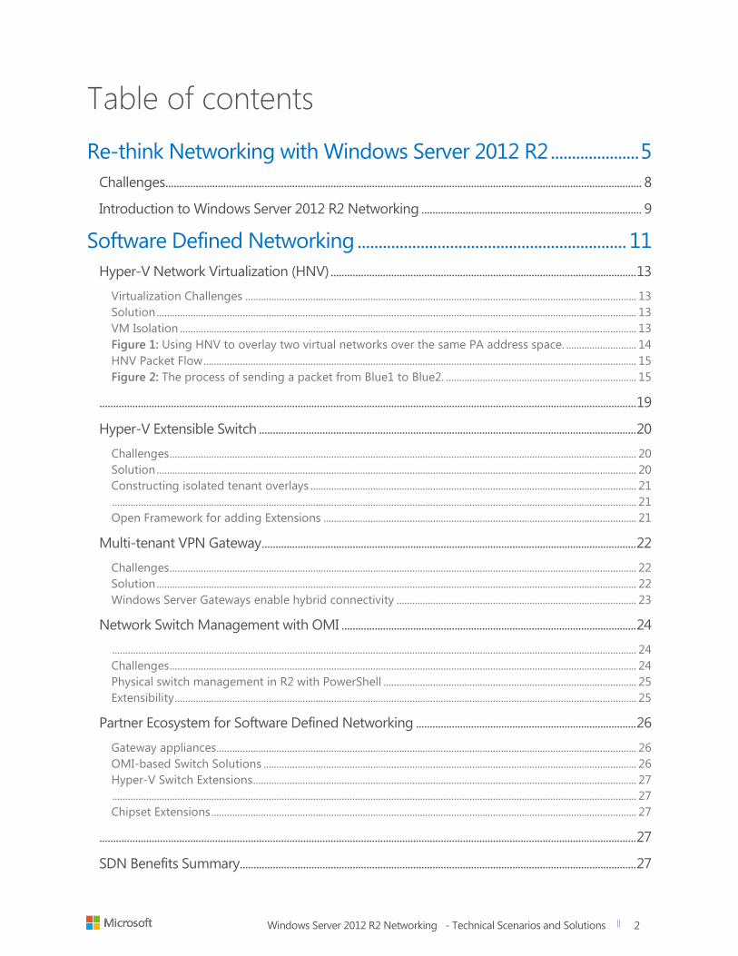
Table of contents
Re-think Networking with Windows Server 2012 R2 ..................... 5
Challenges ............................................................................................................................................................................. 8
Introduction to Windows Server 2012 R2 Networking ................................................................................ 9
Software Defined Networking ................................................................ 11
Hyper-V Network Virtualization (HNV) ............................................................................................................... 13
Virtualization Challenges ...................................................................................................................................................... 13 Solution ........................................................................................................................................................................................ 13 VM Isolation ............................................................................................................................................................................... 13 Figure 1: Using HNV to overlay two virtual networks over the same PA address space. ........................... 14 HNV Packet Flow ...................................................................................................................................................................... 15 Figure 2: The process of sending a packet from Blue1 to Blue2. ......................................................................... 15
................................................................................................................................................................................................... 19
Hyper-V Extensible Switch ......................................................................................................................................... 20
Challenges ................................................................................................................................................................................... 20 Solution ........................................................................................................................................................................................ 20 Constructing isolated tenant overlays ............................................................................................................................. 21 ......................................................................................................................................................................................................... 21 Open Framework for adding Extensions ........................................................................................................................ 21
Multi-tenant VPN Gateway ........................................................................................................................................ 22
Challenges ................................................................................................................................................................................... 22 Solution ........................................................................................................................................................................................ 22 Windows Server Gateways enable hybrid connectivity ............................................................................................ 23
Network Switch Management with OMI ........................................................................................................... 24
......................................................................................................................................................................................................... 24 Challenges ................................................................................................................................................................................... 24 Physical switch management in R2 with PowerShell ................................................................................................. 25 Extensibility ................................................................................................................................................................................. 25
Partner Ecosystem for Software Defined Networking ................................................................................ 26
Gateway appliances ................................................................................................................................................................. 26 OMI-based Switch Solutions ............................................................................................................................................... 26 Hyper-V Switch Extensions ................................................................................................................................................... 27 ......................................................................................................................................................................................................... 27 Chipset Extensions ................................................................................................................................................................... 27
................................................................................................................................................................................................... 27
SDN Benefits Summary................................................................................................................................................ 27
Windows Server 2012 R2 Networking - Technical Scenarios and Solutions
title of document
3
3
Networking solutions that deliver continuous application
availability .......................................................................................................... 28
Network fault tolerance with SMB Multi-channel ......................................................................................... 28
Challenges ................................................................................................................................................................................... 28 Solution ........................................................................................................................................................................................ 28
Highly Available DHCP Service ................................................................................................................................ 30
Challenges ................................................................................................................................................................................... 30 Windows Server 2012 R2 DHCP Failover ........................................................................................................................ 30 Hot standby mode ................................................................................................................................................................... 31 Load-sharing mode ................................................................................................................................................................. 32
Predictable performance with Quality of Service........................................................................................... 33
Challenge ..................................................................................................................................................................................... 33 Solution ........................................................................................................................................................................................ 33 Why this matters ...................................................................................................................................................................... 34
NIC Teaming ...................................................................................................................................................................... 35
Challenges ................................................................................................................................................................................... 35 Solution ........................................................................................................................................................................................ 35 Dynamic NIC Teaming ........................................................................................................................................................... 36
High-performance networking with current and next-
generation hardware ................................................................................... 38
SMB Direct (RDMA) ....................................................................................................................................................... 38
Challenges ................................................................................................................................................................................... 38 Solution ........................................................................................................................................................................................ 38
Virtual Receive Side Scaling (vRSS) ........................................................................................................................ 41
Challenges ................................................................................................................................................................................... 41 Solution ........................................................................................................................................................................................ 41
Dynamic Virtual Machine Queue ............................................................................................................................ 42
Challenge ..................................................................................................................................................................................... 42 With VMQ ................................................................................................................................................................................... 42 With Dynamic VMQ ................................................................................................................................................................ 42
Single Root I/O Virtualization (SR-IOV) ............................................................................................................... 43
Challenges ................................................................................................................................................................................... 43
Windows Server 2012 R2 IP Address Management (IPAM) .................................................................... 45
Challenges ................................................................................................................................................................................... 45 Solution ........................................................................................................................................................................................ 45 Fine-grained administrative control ................................................................................................................................. 45 Highly scalable and customizable ..................................................................................................................................... 45 IPAM Distributed Architecture ............................................................................................................................................ 46

Windows Server 2012 R2 Networking - Technical Scenarios and Solutions
title of document
4
4
IPAM Centralized Architecture ............................................................................................................................................ 46 Figure 25: A centralized deployment of IPAM ............................................................................................................. 47 IPAM monitoring ...................................................................................................................................................................... 47 IPAM data collection tasks ................................................................................................................................................... 48
Operational efficiency through simplified manageability ......... 49
Windows .............................................................................................................................................................................. 49
PowerShell Support ....................................................................................................................................................... 49
Figure 25: Windows PowerShell Benefits ....................................................................................................................... 49
Hyper-V Resource Metering ..................................................................................................................................... 49
Challenges ................................................................................................................................................................................... 49 Solution ........................................................................................................................................................................................ 49 Figure 26: A multi-tenant environment built with Hyper-V. ................................................................................... 50
Remote Live Monitoring ............................................................................................................................................. 51
Challenges ................................................................................................................................................................................... 51 Solution ........................................................................................................................................................................................ 51
Networking and isolation in the Private Cloud using System Center 2012..................................... 52
Challenges ................................................................................................................................................................................... 52
System Center 2012 R2 Virtual Machine Manager ....................................................................................... 53
Challenges ................................................................................................................................................................................... 53 Solution ........................................................................................................................................................................................ 53 Virtual Network Isolation ...................................................................................................................................................... 54 Load Balancers .......................................................................................................................................................................... 55 Network Virtualization Gateway ......................................................................................................................................... 56
System Center 2012 R2 Operations Manager ................................................................................................. 56
Comprehensive end-to-end view of network ............................................................................................................... 57 System Center 2012 R2 Customer Benefits ................................................................................................................... 58
Networking in the Hybrid Cloud ........................................................... 60
Challenges ................................................................................................................................................................................... 60 Solution ........................................................................................................................................................................................ 60 Hybrid Networking in Windows Server 2012 ................................................................................................................ 61 Figure 34: Hybrid networking in Windows Server 2012. ......................................................................................... 61 Hybrid Networking in Windows Server 2012 R2 ......................................................................................................... 61
Connecting Private Cloud with Azure and Hoster ........................................................................................ 62
Summary ........................................................................................................... 63
Windows Server 2012 R2 Networking - Technical Scenarios and Solutions
title of document
5
5
Overview
The exponential growth of available data has created significant challenges
for IT storage. For company networks, big data has consistently increased
network demands. This reality along with today’s heavily virtualized
infrastructures is heavily impacting network performance.
Networking enhancements to Windows Server 2012 R2 however, make it
easier to virtualize workloads, improve security, provide continuous
availability to applications, and get better performance out of existing
resources. These enhancements help improve virtual machine density,
mobility, and availability.
The purpose of this whitepaper is to explore different network challenges
and reveal how new and enhanced features in Windows Server 2012 R2
addresses each one of them. This paper will also illustrate at length how to
scale out Hyper-V servers, and the workloads that run on them, in a multi-
tenant environment. This scenario includes all the services and features that
combine to deliver scalable, reliable, and highly available applications.

Windows Server 2012 R2 Networking - Technical Scenarios and Solutions
title of document
6
6
Here is a quick view of the some of the new and enhanced networking features of Windows Server 2012
R2 and System Center 2012 R2:
Layer Feature Description
Software Defined
Networking
Hyper-V Network
Virtualization (HNV)
Abstraction of virtual networks from the physical
network infrastructure, for multi-tenant isolation
and ease of management
Software Defined
Networking
Hyper-V Extensible Switch
A layer-2 virtual interface that provides
programmatically managed and extensible
capabilities to connect virtual machines to the
physical network
Software Defined
Networking
Multi-tenant VPN Gateway A gateway that easily extends virtual networking
environments outside of the private datacenter to
a hosted cloud environment using NVGRE routing
Software Defined
Networking
Network Switch
Management with OMI
A DMTF standard for datacenter devices and
platform abstractions
Software Defined
Networking
Partner Ecosystem for
Software Defined
Networking
Partner Solutions for various components of
physical and virtual networking
Continuous
Availability
Network fault tolerance
with SMB Multi-channel
Redundant network path support for SMB
sessions
Continuous
Availability
Highly Available DHCP
Service
Failover support for enterprise DHCP services in
either a load sharing or hot-standby mode
Continuous
Availability
Network QoS Management of available virtual machine (VM)
bandwidth using a policy that moves with the VM
during VM migration
Continuous
Availability
NIC Teaming LBFO support inbox for any group of NICs
Performance with
Next Generation
Hardware
SMB Direct (RDMA) Performance enhancement feature that takse
advantage of RDMA NICs and performs CPU
offload for network-heavy workloads
Performance with
Next Generation
Hardware
Virtual Receive Side Scaling
(vRSS)
Efficient CPU distribution of receive-side network
processing tasks; can be extended into a VM with
multiple logical processors
Performance with
Next Generation
Hardware
Dynamic VMQ Dynamic allocations of processor cores for
efficient processing of Hyper-V virtual switch
requests.
Windows Server 2012 R2 Networking - Technical Scenarios and Solutions
title of document
7
7
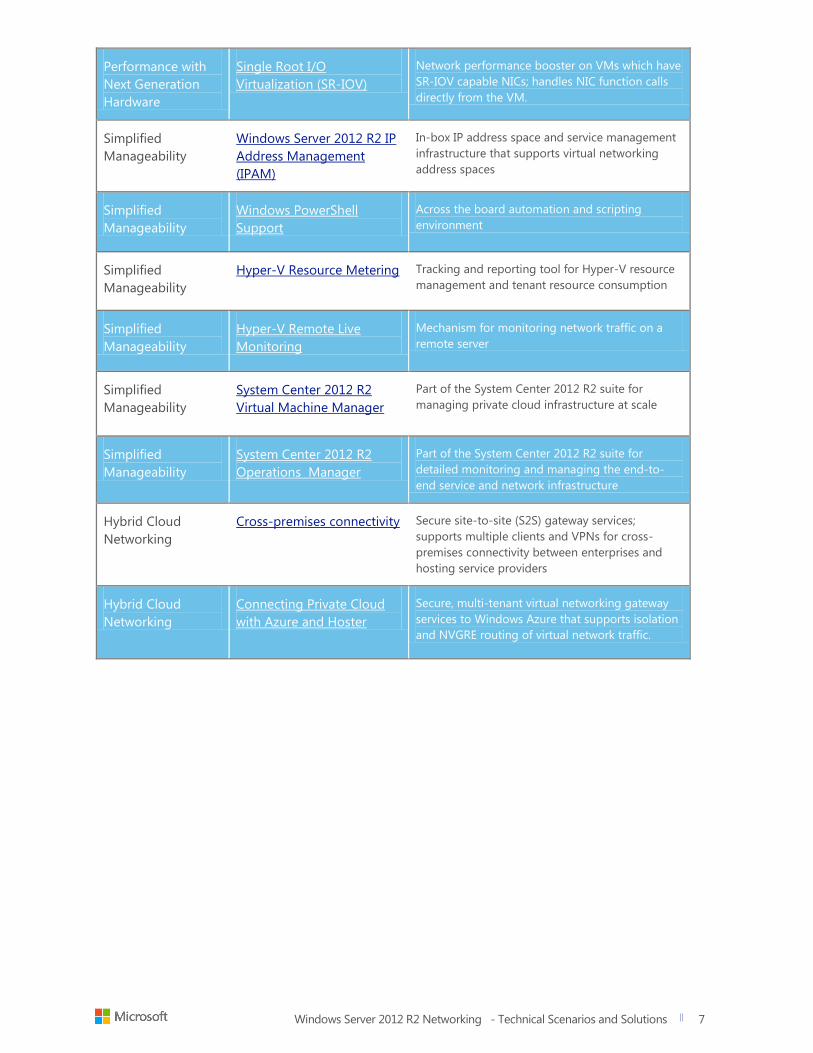
Performance with
Next Generation
Hardware
Single Root I/O
Virtualization (SR-IOV)
Network performance booster on VMs which have
SR-IOV capable NICs; handles NIC function calls
directly from the VM.
Simplified
Manageability
Windows Server 2012 R2 IP
Address Management
(IPAM)
In-box IP address space and service management
infrastructure that supports virtual networking
address spaces
Simplified
Manageability
Windows PowerShell
Support
Across the board automation and scripting
environment
Simplified
Manageability
Hyper-V Resource Metering Tracking and reporting tool for Hyper-V resource
management and tenant resource consumption
Simplified
Manageability
Hyper-V Remote Live
Monitoring
Mechanism for monitoring network traffic on a
remote server
Simplified
Manageability
System Center 2012 R2
Virtual Machine Manager
Part of the System Center 2012 R2 suite for
managing private cloud infrastructure at scale
Simplified
Manageability
System Center 2012 R2
Operations Manager
Part of the System Center 2012 R2 suite for
detailed monitoring and managing the end-to-
end service and network infrastructure
Hybrid Cloud
Networking
Cross-premises connectivity Secure site-to-site (S2S) gateway services;
supports multiple clients and VPNs for cross-
premises connectivity between enterprises and
hosting service providers
Hybrid Cloud
Networking
Connecting Private Cloud
with Azure and Hoster
Secure, multi-tenant virtual networking gateway
services to Windows Azure that supports isolation
and NVGRE routing of virtual network traffic.
Windows Server 2012 R2 Networking - Technical Scenarios and Solutions
title of document
8
8
Challenges
Networking demands are larger today than ever before. A major challenge
for IT professionals is keeping up to speed with constantly increasing
network demands emanating from the exponential growth of corporate
data. With the influx of big data and social networking data, IT staffs must
find efficient methods to create, store, report on and archived information.
Adding to the challenge are evolving infrastructures that IT must find ways
to integrate into their existing environments. For example, incorporating
private and public cloud implementations is a relatively new component that
more and more companies want to utilize in the workplace. Some of these
moving parts overlap with no clear lines to delineate the best path to go
down.
Within this framework, more and more companies are turning to
virtualization as a viable solution. To this end, IT staffs must find effective
resources for integrating virtualization into their current architecture. This
can present many challenges. Some of the most notable within a large,
multi-tenant environment are as follows:
Physical networks lack the flexibility of software-defined networks
Continuous availability (CA) of applications and guaranteed Quality
of Service (QoS) must extend beyond the datacenter into hosted
environments with end-to-end network monitoring and
troubleshooting tools
Virtual workloads need to take advantage of hardware innovations
such as NUMA and RDMA
Customers need to get maximum performance from existing
hardware
Windows Server 2012 R2 Networking - Technical Scenarios and Solutions
title of document
9
9
Introduction
to Windows
Server 2012
R2
Networking
Windows Server 2012 R2 introduces many new and enhanced technologies
in the area of virtual networking that enable easier setup, management, and
troubleshooting of Hyper-V Network Virtualization (HNV) infrastructures.
With HNV, companies gain a much-needed layer of abstraction between the
physical networks that host run on and the logical networks that virtualized
workloads run on.
Physical networks need to be able to support and isolate multiple virtual
networks. Virtual networks need to be able to span multiple physical
networks. These needs go beyond PVLAN setup. HNV provides this
flexibility with advanced packet filtering and routing through the Hyper-V
Extensible Switch, multi-tenant gateway services, and System Center 2012.
The Hyper-V Extensible Switch offer customers and partners an open
development framework for adding layer-2 functionality such as filtering,
monitoring, and packet-level redirection needed to fulfill the requirements
of the application or tenant.
SMB Multi-Channel and Network Quality of Service (QoS) help improve
application availability over physical and virtual networks by guaranteeing
that multiple paths are available to application shares and that there is
enough available bandwidth reserved for the application to function at levels
set forth by SLA.
In addition, improvements to network infrastructure availability such as
DHCP Failover help ensure that DHCP services never go down. Windows
Server 2012 and higher DCHP Servers can now operate in a failover
relationship with a partner DCHP server. The partnership can operate in
either a load sharing mode (fault tolerant), or hot standby mode (highly
available). This gives network administrators the ability to have their
enterprise DHCP scopes serviced by a topology of DHCP Servers.
To take advantage of new industry-standard hardware technologies within
virtualized workloads, Windows Server 2012 and R2 support Remote Direct
Memory Access (RDMA) to file servers through the implementation of
SMB Direct. For virtualized workloads with heavy networking demands,
Single Root IO Virtualization (SRIOV) connects the physical NIC or team
used on the host directly to one or more VM's. This speeds the throughput
to the VM by bypassing the Hyper-V Virtual Switch and mapping NIC virtual
functions directly to the VM network adapter.
Windows Server R2 also offers Receive Side Scaling (RSS). With RSS, the
processing job of clearing network buffers is spread across all CPU's. In
Windows Sever 2012, this was limited to the host machine. Virtual Receive
Side Scaling (vRSS), another new feature, builds on RSS by extending this
capability to the VM and enabling all virtual processors assigned to the VM
to be used to clear network buffers for the VM. This change substantially
increases the networking capabilities of VMs on a host by eliminating CPU
bottlenecks that can limit 10 and 40 GB Ethernet throughputs.
For scalability, Windows Server R2 offers IP Address Management Server
(IPAM), a centralized or decentralized management console that can
manage, track, and report on all aspects of a data center's IP address
Windows Server 2012 R2 Networking - Technical Scenarios and Solutions
title of document
10
10
space. IPAM can manage server groups of DHCP and DNS servers from a
central console capable of applying changes to groups of servers at once. In
addition, PowerShell gives network administrators the power to set up
script and deployment options for advanced services. PowerShell also
reduces the need for interface training as well as the risk of configuration
errors. System Center 2012 R2 Virtual Machine Manager also greatly
improves private cloud and VM manageability by providing a single control
plane to manage compute, storage and networking needs at scale.
To close the gaps between on-premise Hyper-V hosts and hybrid cloud
environments offered by hosters, Windows Server 2012 R2 provides Cross-
Premise Connectivity to a variety of hosters along with services and tools
that seamlessly extend your private cloud to Azure.
This whitepaper focuses on five categories of features and services that
make these capabilities possible:
1. Advanced Software-Defined Networking
2. The delivery of Continuous Availability
3. High Performance Networking
4. Simplified Data Center Management
5. Networking in the Hybrid Cloud
For more information on all Windows Server 2012 and 2012 R2 Networking
Features, see: http://technet.microsoft.com/en-us/library/hh831357.aspx
Windows Server 2012 R2 Networking - Technical Scenarios and Solutions
title of document
11
11
With software-defined networking (SDN), you enable software to
dynamically manage your network. SDN does not mean replacing your
existing network devices with new “SDN-aware devices”. In most cases, the
most flexible and cost-effective network infrastructure is the one you already
own. If your network can scale to meet your needs and the demands of a
modern datacenter, then there’s less of a pressing need to turn to SDN. In
many instance however, companies must deal with inflexible, hard-wired
solutions that are complex and expensive to update. In these instances, a
company can take one of two approaches to address these challenges:
Isolate virtual networks/network overlays
Centralize controllers
Isolated virtual networks/network overlays sit on top of the physical network,
abstracted from the underlying networking hardware. Since virtual networks
are software defined, administrators can create and manage them from a
centralized location. Depending on the needs of the application, templates
may be used for easy deployment and replication across the datacenter. This
helps greatly reduce management overhead. In addition, many mundane,
error-prone tasks become automated as a part of the virtual network
definition. Customers utilize existing hardware investments without the need
to change the way applications are written. Hyper-V Network Virtualization
and VMware’s Nicira serve as two examples of solutions that fall within this
category.
Centralized controllers manage the physical network infrastructure directly
from a single location. This functionality often get paired with an API for
programming the network, giving software and potentially even applications
the ability to program and dynamically configure the network on the fly
depending on current needs. Such a solution requires switches and routers
to expose these functionalities (Southbound APIs) and a standardized
interface for applications to consume them (Northbound APIs). OpenFlow
and Cisco One Platform kit offer examples of such an approach. Since
software directly configures the network, it needs to be rewritten to make
use of this functionality. Custom applications that run within large
datacenters, network diagnostic tools, apps that requires high-fidelity
connections, and so on can perform better with such fine-grained control.
The cornerstone of SDN is network virtualization. Network virtualization
helps you isolate VM's from one another as well as bring VM's together into
common virtual networks that can span physical IP subnets or physical
datacenters. Network virtualization uses encapsulation and virtual network
ID headers to filter and route VM-to-VM traffic based on policy. To
overcome the proximity limitations of physical VLAN's, network virtualization
Windows Server 2012 R2 Networking - Technical Scenarios and Solutions
title of document
12
12
routes packets between two VMs on the same virtual network, even if those
two VMs are in separate datacenters. Network virtualization also helps you
meet the requirements of your applications and workloads by giving you the
ability to abstract them from the underlying physical network infrastructure.
Analogous to server virtualization, you need consistent and repeatable
logical network abstractions that work with your applications and workloads
in a non-disruptive manner while maintaining consistency across the tenant
address space and the hoster address space. For instance, you would need
virtual abstractions for your physical network elements, such as IP addresses,
switches, and load balancers in a multi-tenant scenario. Additionally,
network virtualization gives you the ability to centrally define and control
policies that govern both physical and virtual networks, including traffic flow
between them. The ability to implement these network policies in a
consistent manner, at scale, even as new workloads are deployed or moved
around across virtualized or physical networks provides the core of SDN
functional With SDN, logical networks overlay physical networks. This
provides a higher degree of control and flexibility than the physical network
could deliver alone. Network virtualization gives IT pros the flexibility and
control to configure the network to support any landscape and the
automation needed to make changes repeatable to other virtual networks.
One of the core enablers of SDN is the Hyper-V Extensible Switch. The
Hyper-V Extensible Switch is an open platform for partners and customers to
add functionality on top of the already rich virtual switch feature set. The
goal is to use the power of software to perform activities such as forwarding,
filtering, and capturing packets.
With multiple services sharing the same physical network infrastructure, the
need to isolate traffic and communication between VMs and services has
never been more important. Windows Server 2012 R2 makes it easier to
troubleshoot, isolate, and fix issues through better interaction with storage,
network, and server admin tools. Since physical networks are not nearly as
flexible as virtual networks, the virtual networks you create, with the Hyper-V
Network Virtualization, mask the complexities of the underlying physical
infrastructure from those that are responsible for provisioning workload.
Windows Server 2012 R2 Networking - Technical Scenarios and Solutions
title of document
13
13
Hyper-V Network
Virtualization (HNV)
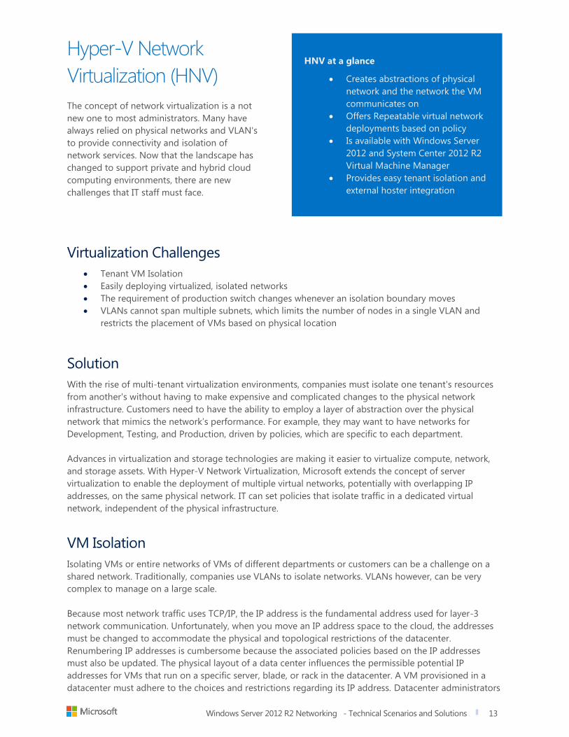
The concept of network virtualization is a not
new one to most administrators. Many have
always relied on physical networks and VLAN's
to provide connectivity and isolation of
network services. Now that the landscape has
changed to support private and hybrid cloud
computing environments, there are new
challenges that IT staff must face.
Virtualization Challenges
Tenant VM Isolation
Easily deploying virtualized, isolated networks
The requirement of production switch changes whenever an isolation boundary moves
VLANs cannot span multiple subnets, which limits the number of nodes in a single VLAN and
restricts the placement of VMs based on physical location
Solution
With the rise of multi-tenant virtualization environments, companies must isolate one tenant's resources
from another's without having to make expensive and complicated changes to the physical network
infrastructure. Customers need to have the ability to employ a layer of abstraction over the physical
network that mimics the network’s performance. For example, they may want to have networks for
Development, Testing, and Production, driven by policies, which are specific to each department.
Advances in virtualization and storage technologies are making it easier to virtualize compute, network,
and storage assets. With Hyper-V Network Virtualization, Microsoft extends the concept of server
virtualization to enable the deployment of multiple virtual networks, potentially with overlapping IP
addresses, on the same physical network. IT can set policies that isolate traffic in a dedicated virtual
network, independent of the physical infrastructure.
VM Isolation
Isolating VMs or entire networks of VMs of different departments or customers can be a challenge on a
shared network. Traditionally, companies use VLANs to isolate networks. VLANs however, can be very
complex to manage on a large scale.
Because most network traffic uses TCP/IP, the IP address is the fundamental address used for layer-3
network communication. Unfortunately, when you move an IP address space to the cloud, the addresses
must be changed to accommodate the physical and topological restrictions of the datacenter.
Renumbering IP addresses is cumbersome because the associated policies based on the IP addresses
must also be updated. The physical layout of a data center influences the permissible potential IP
addresses for VMs that run on a specific server, blade, or rack in the datacenter. A VM provisioned in a
datacenter must adhere to the choices and restrictions regarding its IP address. Datacenter administrators
HNV at a glance
Creates abstractions of physical
network and the network the VM
communicates on
Offers Repeatable virtual network
deployments based on policy
Is available with Windows Server
2012 and System Center 2012 R2
Virtual Machine Manager
Provides easy tenant isolation and
external hoster integration
Windows Server 2012 R2 Networking - Technical Scenarios and Solutions
title of document
14
14
typically assign IP addresses from the datacenter address space to the VMs. This forces VM owners to
adjust their isolation policies, which were based on the original server IP addresses. This renumbering
becomes so complex that many enterprises choose to deploy only new services into the cloud, leaving
existing applications unchanged.
HNV gives each virtual machine two IP addresses; the customer address (CA) and the provider address
(PA).
The CA is the IP address that the customer assigns based on the customer’s own intranet
infrastructure.
- This address is used by the customer VMs and applications to maintain consistency to the
customer IP address space
- The CA is visible to the VM and reachable by the customer
The PA is the IP address that the host assigns based on the host’s physical network infrastructure.
- The PA appears in the packets that go out onto the wire (versus being routed internally
by the Hyper-V Switch).
- The PA routes the packets to the correct physical host that the destination VM is on. The
PA is visible on the physical network, but not to the VM.
- The layer of CAs is consistent with the customer's network topology, which is virtualized
and decoupled from the underlying physical network addresses, as implemented by the
layer of PAs
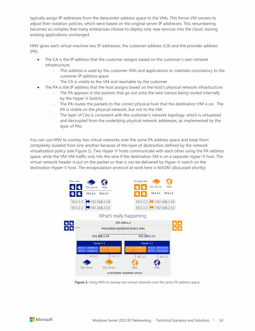
You can use HNV to overlay two virtual networks over the same PA address space and keep them
completely isolated from one another because of the layer of abstraction defined by the network
virtualization policy (see Figure 1). Two Hyper-V hosts communicate with each other using the PA address
space, while the VM-VM traffic only hits the wire if the destination VM is on a separate Hyper-V host. The
virtual network header is put on the packet so that is can be delivered by Hyper-V switch on the
destination Hyper-V host. The encapsulation protocol at work here is NVGRE (discussed shortly).
Figure 1: Using HNV to overlay two virtual networks over the same PA address space.
Windows Server 2012 R2 Networking - Technical Scenarios and Solutions
title of document
15
15
HNV Packet Flow
HNV enables you to break down the packet flow
over two HNV networks using the NVGRE
encapsulation protocol. NVGRE (Network
Virtualization using Generic Routing
Encapsulation) provides a network virtualization
method that uses encapsulation and tunneling to
create large numbers of VLANs for subnets that
can extend across a dispersed datacenter. The
purpose is to enable the sharing of multi-tenant
and load-balanced networks across on-premises
and cloud environments.
NVGRE was designed to solve problems caused by
the limited number of VLANs that the IEEE 802.1Q
specification could enable. This limitation often
proved inadequate for complex virtualized
environments, making it difficult to stretch
network segments over the long distances
required for dispersed data centers.
NVGRE includes key features such as identifying a
24-bit Tenant Network Identifier (TNI) to address
problems associated with the multi-tenant
network and using a Generic Routing
Encapsulation (GRE). The TNI is used to create an
isolated virtual Layer 2 network that may be
confined to a single physical Layer-2 network or
extend across subnet boundaries. NVGRE also
isolates individual TNIs by inserting the TNI value
in the GRE header.
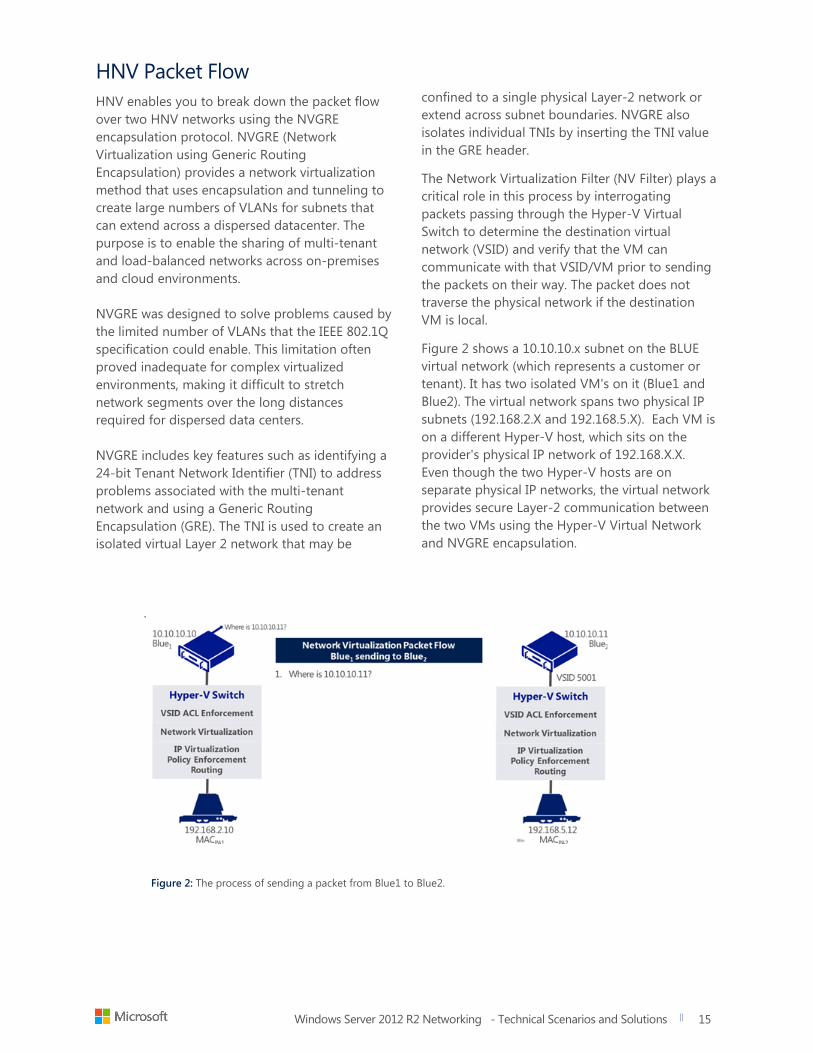
The Network Virtualization Filter (NV Filter) plays a
critical role in this process by interrogating
packets passing through the Hyper-V Virtual
Switch to determine the destination virtual
network (VSID) and verify that the VM can
communicate with that VSID/VM prior to sending
the packets on their way. The packet does not
traverse the physical network if the destination
VM is local.
Figure 2 shows a 10.10.10.x subnet on the BLUE
virtual network (which represents a customer or
tenant). It has two isolated VM's on it (Blue1 and
Blue2). The virtual network spans two physical IP
subnets (192.168.2.X and 192.168.5.X). Each VM is
on a different Hyper-V host, which sits on the
provider's physical IP network of 192.168.X.X.
Even though the two Hyper-V hosts are on
separate physical IP networks, the virtual network
provides secure Layer-2 communication between
the two VMs using the Hyper-V Virtual Network
and NVGRE encapsulation.
.
Figure 2: The process of sending a packet from Blue1 to Blue2.
Windows Server 2012 R2 Networking - Technical Scenarios and Solutions
title of document
16
16
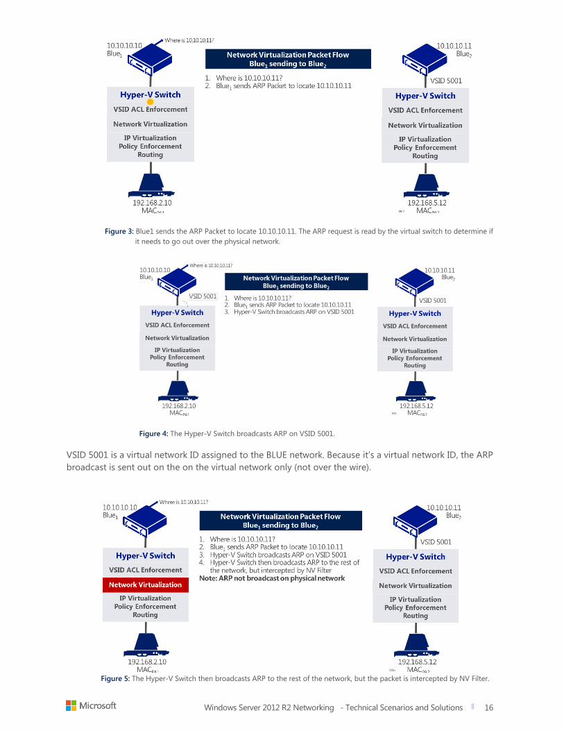
Figure 3: Blue1 sends the ARP Packet to locate 10.10.10.11. The ARP request is read by the virtual switch to determine if
it needs to go out over the physical network.
Figure 4: The Hyper-V Switch broadcasts ARP on VSID 5001.
VSID 5001 is a virtual network ID assigned to the BLUE network. Because it’s a virtual network ID, the ARP
broadcast is sent out on the on the virtual network only (not over the wire).
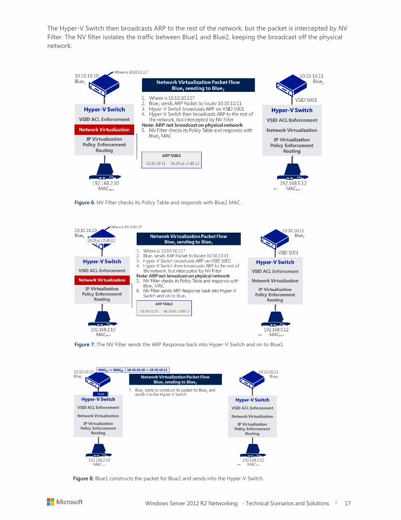
Figure 5: The Hyper-V Switch then broadcasts ARP to the rest of the network, but the packet is intercepted by NV Filter.
Windows Server 2012 R2 Networking - Technical Scenarios and Solutions
title of document
17
17
The Hyper-V Switch then broadcasts ARP to the rest of the network, but the packet is intercepted by NV
Filter. The NV filter isolates the traffic between Blue1 and Blue2, keeping the broadcast off the physical
network.
Figure 6: NV Filter checks its Policy Table and responds with Blue2 MAC.
Figure 7: The NV Filter sends the ARP Response back into Hyper-V Switch and on to Blue1.
Figure 8: Blue1 constructs the packet for Blue2 and sends into the Hyper-V Switch.
Windows Server 2012 R2 Networking - Technical Scenarios and Solutions
title of document
18
18
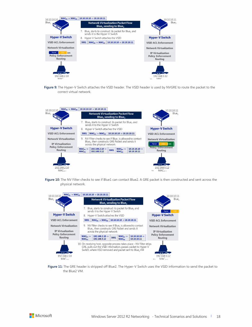
Figure 9: The Hyper-V Switch attaches the VSID header. The VSID header is used by NVGRE to route the packet to the
correct virtual network.
Figure 10: The NV Filter checks to see if Blue1 can contact Blue2. A GRE packet is then constructed and sent across the
physical network.
Figure 11: The GRE header is stripped off Blue2. The Hyper-V Switch uses the VSID information to send the packet to
the Blue2 VM.
Windows Server 2012 R2 Networking - Technical Scenarios and Solutions
title of document
19
19
With HNV, customers can now host multi-tenant
environments in Hyper-V without changing the
underlying physical network infrastructure. HNV
gives network administrators a way to overlay as
many logical networks as needed over the top of
the physical network infrastructure to provide
isolation or extend logical address spaces to
remote IP networks and cloud hosters. When you
combine HNV with the power of System Center
Virtual Machine Manager 2012 and partner
extensions, you have the flexibility, automation,
and control to operate in any environment, and
across hybrid clouds, without changing hardware
or investing in new vendor solutions. This
technology can be deployed at scale using Virtual
Machine Manager and HVN gateways such as the
Multi-tenant VPN gateway.
HVN Benefits at a glance:
Easy deployment of virtualized, isolated networks
Flexible Tenant Isolation
Ability to overcome limitations of VLAN's
Customer IP Address Space can be persisted to the cloud
NVGRE encapsulation end-to-end with hosters
Windows Server 2012 R2 Networking - Technical Scenarios and Solutions
title of document
20
20
Hyper-V Extensible Switch
The Hyper-V Extensible Switch is a layer-2 virtual interface that provides programmatically managed and
extensible capabilities to connect VMs to the physical network.
Challenges
Customize functionality of Hyper-V
Switches to meet individual monitoring
and management needs
Better monitoring needed for VM-to-VM
traffic
Better flexibility in existing network
Solution
Windows Server 2012 R2 further enhances the
Hyper-V Extensible Switch feature introduced
with Windows Server 2012. Management
features built into the Hyper-V Extensible Switch
enable you to manage network traffic as well as
troubleshoot and resolve problems on Hyper-V
Extensible Switch networks. With the Hyper-V
Extensible Switch, extensions are tightly
integrated with traffic flow through the virtual
switch, enabling a more flexible policy edge (see
Figure 12).
The first step towards gaining flexibility in your
existing network is to move the policy edge (i.e.
the application of ACLs, QoS, isolation and so
on) from the physical switch in the network to
the virtual switches on the host (where possible)
instead. Such a move makes your existing
network more consistently manageable and
automated with software. A key aspect of the
switch is the extensibility, which enables capture
extensions (such as InMon’s sFlow extension),
filter extensions, (such as 5Nine’s firewall
extension) and forwarding extensions (such as
NEC’s OpenFlow extension or Cisco’s Nexus
1000V extension) to co-exist with each other.
Windows Server 2012 R2 enables firewall-like
capabilities in the switch. With Extended ACLs,
you now gain the ability to apply weighted,
stateful rules that enable or deny traffic based
on source/destination IP addresses and port
numbers. This lets you set ACLs not just for a
VM, but workloads running in the VM as well.
Hyper-V Extensible Switch at a glance:
New open framework for adding
switch extensions
Workload-level Security
Full traffic monitoring tools
Ability to Identify out-of-bound
traffic patterns and potential
exploits
Stateful packet inspection
PowerShell instrumented
Windows Server 2012 R2 Networking - Technical Scenarios and Solutions
title of document
21
21
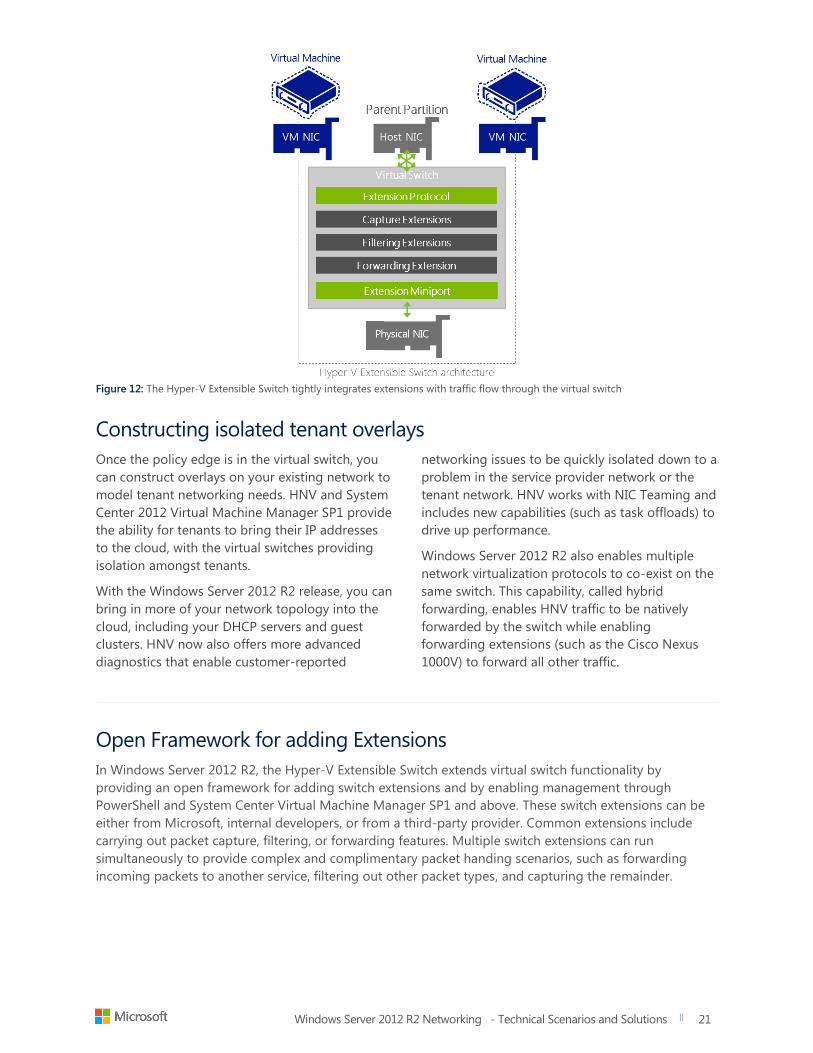
Figure 12: The Hyper-V Extensible Switch tightly integrates extensions with traffic flow through the virtual switch
Constructing isolated tenant overlays
Once the policy edge is in the virtual switch, you
can construct overlays on your existing network to
model tenant networking needs. HNV and System
Center 2012 Virtual Machine Manager SP1 provide
the ability for tenants to bring their IP addresses
to the cloud, with the virtual switches providing
isolation amongst tenants.
With the Windows Server 2012 R2 release, you can
bring in more of your network topology into the
cloud, including your DHCP servers and guest
clusters. HNV now also offers more advanced
diagnostics that enable customer-reported
networking issues to be quickly isolated down to a
problem in the service provider network or the
tenant network. HNV works with NIC Teaming and
includes new capabilities (such as task offloads) to
drive up performance.
Windows Server 2012 R2 also enables multiple
network virtualization protocols to co-exist on the
same switch. This capability, called hybrid
forwarding, enables HNV traffic to be natively
forwarded by the switch while enabling
forwarding extensions (such as the Cisco Nexus
1000V) to forward all other traffic.
Open Framework for adding Extensions
In Windows Server 2012 R2, the Hyper-V Extensible Switch extends virtual switch functionality by
providing an open framework for adding switch extensions and by enabling management through
PowerShell and System Center Virtual Machine Manager SP1 and above. These switch extensions can be
either from Microsoft, internal developers, or from a third-party provider. Common extensions include
carrying out packet capture, filtering, or forwarding features. Multiple switch extensions can run
simultaneously to provide complex and complimentary packet handing scenarios, such as forwarding
incoming packets to another service, filtering out other packet types, and capturing the remainder.
Windows Server 2012 R2 Networking - Technical Scenarios and Solutions
title of document
22
22
Multi-tenant VPN Gateway
The Multi-tenant VPN Gateway is a new feature of
Windows Server 2012 R2 and System Center 2012
R2 that enables customers and hosters to setup a
single gateway for VPN, NAT, and NVGRE
connectivity to multiple private clouds, through a
single entry point, while still maintaining isolation,
even in overlapping NAT and NVGRE networks.
Customers running private clouds can use this
fucntionality to extend multiple virtual networks
beyond the boundaries of their own datacenter to
another private data center or hosted
environment such as Azure.
Challenges
Customers and hosters need a multi-tenant VPN gateway for S2S cloud links that supports
NVGRE, isolated NAT, and isolated BGP updates
Customers need a high availability gateway device that understands NVGRE traffic, and can
encapsulate and decapsulate packets as they leave the datacenter
Solution
The Windows Server 2012 R2 Multi-tenant
VPN gateway provides a seamless
connection over a S2S VPN link between
multiple external organizations and the
resources that those organizations own in
a hosted cloud. The Multi-tenant VPN
gateway also enables connectivity
between physical and virtual networks,
enterprise data centers, hosting
organizations, and enterprise networks
and Windows Azure. Guest clustering
provides high availability using a hot
standby node. A dynamic link library
ensures the syncing of any routing
configuration from the active node to the
hot standby or when the standby
becomes active.
System Center 2012 R2 Virtual Machine
Manager provides templates for
customers to deploy these gateways
easily and configure them for high-
availability. You also gain the ability to
map VPN networks to virtual networks. To
ensure that routes are updated
dynamically, Windows Server 2012 R2
implements Border Gateway Protocol
(BGP) and incorporates multi-tenant
aware Network Address Translation (NAT)
for Internet access.
In general, the Multi-tenant VPN gateway
works best in the following scenarios:
Hoster needs to provide isolated networks
for tenant VMs with integral S2S VPN and
NAT
Enterprises have virtualized networks split
across different datacenters or virtualized
networks (NVGRE aware) communicating
to physical networks (NVGRE unaware)
Multi-tenant VPN Gateway at a glance
Inbox Multi-tenant NVGRE gateway
without having to run separate VPN's
BGP and NAT for dynamic route
updates
S2S gateway for hosters or enterprises
Highly available with Guest clustering
Windows Server 2012 R2 Networking - Technical Scenarios and Solutions
title of document
23
23
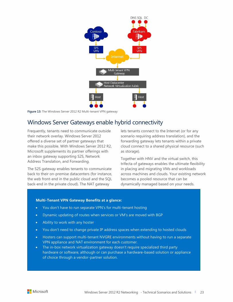
Figure 13: The Windows Server 2012 R2 Multi-tenant VPN gateway
Windows Server Gateways enable hybrid connectivity
Frequently, tenants need to communicate outside
their network overlay. Windows Server 2012
offered a diverse set of partner gateways that
make this possible. With Windows Server 2012 R2,
Microsoft supplements its partner offerings with
an inbox gateway supporting S2S, Network
Address Translation, and Forwarding.
The S2S gateway enables tenants to communicate
back to their on-premise datacenters (for instance,
the web front-end in the public cloud and the SQL
back-end in the private cloud). The NAT gateway
lets tenants connect to the Internet (or for any
scenario requiring address translation), and the
forwarding gateway lets tenants within a private
cloud connect to a shared physical resource (such
as storage).
Together with HNV and the virtual switch, this
trifecta of gateways enables the ultimate flexibility
in placing and migrating VMs and workloads
across machines and clouds. Your existing network
becomes a pooled resource that can be
dynamically managed based on your needs.
Multi-Tenant VPN Gateway Benefits at a glance:
You don’t have to run separate VPN's for multi-tenant hosting
Dynamic updating of routes when services or VM's are moved with BGP
Ability to work with any hoster
You don’t need to change private IP address spaces when extending to hosted clouds
Hosters can support multi-tenant NVGRE environments without having to run a separate
VPN appliance and NAT environment for each customer.
The in-box network virtualization gateway doesn’t require specialized third party
hardware or software, although or can purchase a hardware-based solution or appliance
of choice through a vendor-partner solution.
Windows Server 2012 R2 Networking - Technical Scenarios and Solutions
title of document
24
24
Network Switch
Management with OMI
Today, many datacenters run a wide array of
heterogeneous devices supplied by different
hardware and platform vendors that require
different tools and management processes.
As a result, companies have been forced to
write their own abstraction layer or to be
locked into a single vendor, which limits their
choice and agility.
Challenges Multi-vendor device management is
difficult
Companies have to develop their own
management tools and abstraction layers
Development is expensive, heavy, and not
very portable
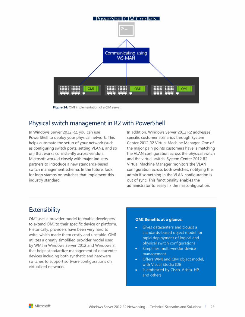
The Open Management Infrastructure (OMI), a
DMTF standard for datacenter devices and
platform abstractions, offers a highly portable,
small footprint, built into the high performance
CIM Object Model. OMI can be used to easily
compile and implement a standards-based
management service into any device or platform.
OMI implements its CIMOM server according to
the DMTF management standard. Microsoft is
working with Arista and Cisco to port OMI to their
network switches for Windows Azure and cloud
datacenters. IT needs this type of abstraction layer
for easy configuration and management of its
logical and physical network infrastructure as well
as the physical platforms and appliances that
support them. Partners that adopt OMI can gain
the following:
DMTF Standards Support: OMI
implements its CIMOM server according
to the DMTF standard
Small System Support: OMI can also be
implemented in small systems (including
embedded and mobile systems)
Easy Implementation: OMI offers a
greatly shortened path to implementing
WS-Management and CIM in your
devices/platforms
Remote Manageability: OMI provides
instant remote manageability from
Windows and non-Windows clients and
servers as well as other WS-Management-
enabled platforms
API compatibility with WMI: Providers
and management applications can be
written on Linux and Windows by using
the same APIs
Support for CIM IDE: OMI offers tools
for generating and developing CIM
providers such as Visual Studio’s CIM IDE
Optional PowerShell Support: If OMI
providers use a set of documented
conventions, Windows PowerShell
discovers and auto-generate cmdlets from
them (This is how many of the 2300+
cmdlets in Windows Server 2012 are
implemented)
For developers, OMI’s small footprint (250KB base
size with a working set memory usage of 1MB)
and high-quality code help reduce the complexity
of developing a high performance, stable
standards-based management stack. For IT pros,
OMI greatly amplifies your effectiveness and
productivity by increasing the number and types
of devices you can manage and by unifying the
management experience with standard-based
management and automation tools, such as
Windows PowerShell, System Center, and other
management solutions.
OMI at a glance:
Standards-based object model for rapid
deployment of logical and physical switch
configurations
Growing Partner Ecosystem
Support for multi-vendor network fabric
Portable, extensible, low overhead
Extensible DTMT-supported provider
model
Windows Server 2012 R2 Networking - Technical Scenarios and Solutions
title of document
25
25
Figure 14: OMI implementation of a CIM server.
Physical switch management in R2 with PowerShell
In Windows Server 2012 R2, you can use
PowerShell to deploy your physical network. This
helps automate the setup of your network (such
as configuring switch ports, setting VLANs, and so
on) that works consistently across vendors.
Microsoft worked closely with major industry
partners to introduce a new standards-based
switch management schema. In the future, look
for logo stamps on switches that implement this
industry standard.
In addition, Windows Server 2012 R2 addresses
specific customer scenarios through System
Center 2012 R2 Virtual Machine Manager. One of
the major pain points customers have is matching
the VLAN configuration across the physical switch
and the virtual switch. System Center 2012 R2
Virtual Machine Manager monitors the VLAN
configuration across both switches, notifying the
admin if something in the VLAN configuration is
out of sync. This functionality enables the
administrator to easily fix the misconfiguration.
Extensibility
OMI uses a provider model to enable developers
to extend OMI to their specific device or platform.
Historically, providers have been very hard to
write, which made them costly and unstable. OMI
utilizes a greatly simplified provider model used
by WMI in Windows Server 2012 and Windows 8,
that helps standardize management of datacenter
devices including both synthetic and hardware
switches to support software configurations on
virtualized networks.
OMI Benefits at a glance:
Gives datacenters and clouds a
standards-based object model for
rapid deployment of logical and
physical switch configurations
Simplifies multi-vendor device
management
Offers WMI and CIM object model,
with Visual Studio IDE
Is embraced by Cisco, Arista, HP,
and others
Windows Server 2012 R2 Networking - Technical Scenarios and Solutions
title of document
26
26
Partner Ecosystem for
Software Defined
Networking
Microsoft has been very busy developing partner
and vendor solutions that extend and enhance the
rich feature set of Windows Server 2012 R2
networking. The primary areas of partner
integration are:
Gateway appliances
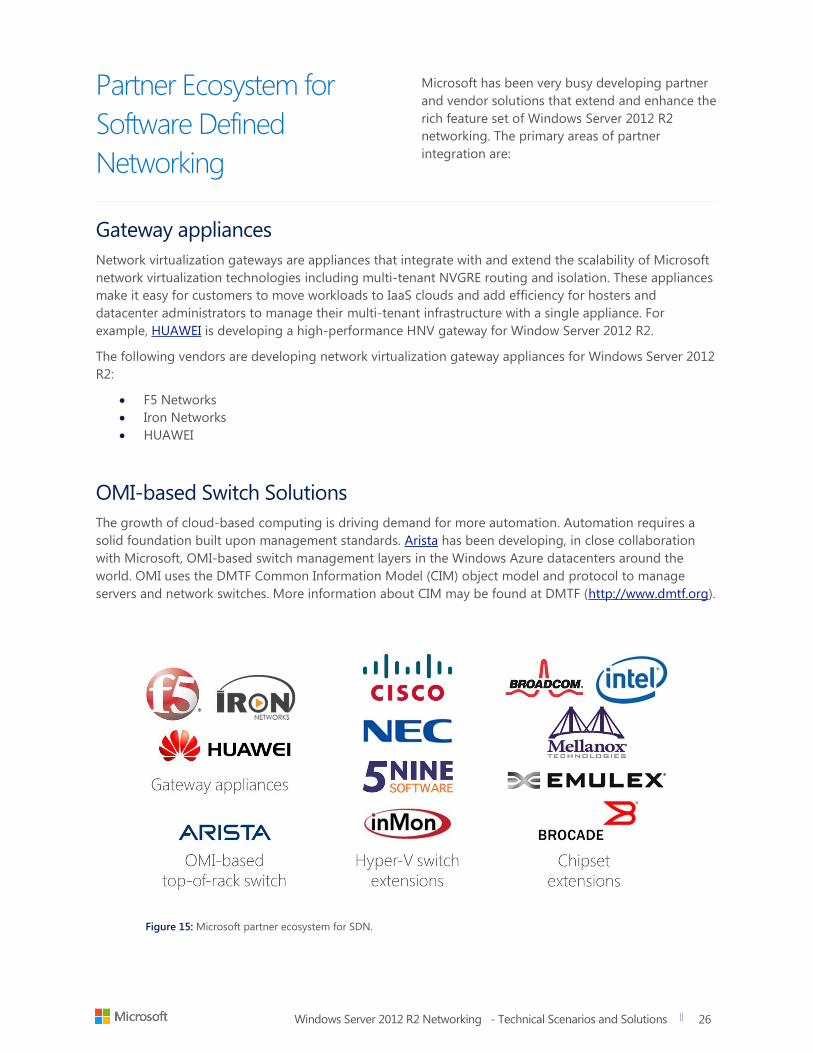
Network virtualization gateways are appliances that integrate with and extend the scalability of Microsoft
network virtualization technologies including multi-tenant NVGRE routing and isolation. These appliances
make it easy for customers to move workloads to IaaS clouds and add efficiency for hosters and
datacenter administrators to manage their multi-tenant infrastructure with a single appliance. For
example, HUAWEI is developing a high-performance HNV gateway for Window Server 2012 R2.
The following vendors are developing network virtualization gateway appliances for Windows Server 2012
R2:
F5 Networks
Iron Networks
HUAWEI
OMI-based Switch Solutions
The growth of cloud-based computing is driving demand for more automation. Automation requires a
solid foundation built upon management standards. Arista has been developing, in close collaboration
with Microsoft, OMI-based switch management layers in the Windows Azure datacenters around the
world. OMI uses the DMTF Common Information Model (CIM) object model and protocol to manage
servers and network switches. More information about CIM may be found at DMTF (http://www.dmtf.org).
Figure 15: Microsoft partner ecosystem for SDN.
Windows Server 2012 R2 Networking - Technical Scenarios and Solutions
title of document
27
27
Hyper-V Switch Extensions
Hyper-V switch extensions provide a
comprehensive and extensible architectural
platform for virtual machine (VM) and cloud
networking. An example of this is the Cisco Nexus
series of switches. The vendor-supplied extensions
accelerate server virtualization and multi-tenant
cloud deployments in a secure and operationally
transparent manner. These solutions integrate into
the Windows Server 2012 and R2 Extensible
Switch and are fully compatible with System
Center Virtual Machine Manager 2012 SP1.
The following vendors provide addition
functionality on their switch infrastructure via
Hyper-V Switch extensions:
Cisco
NEC
5Nine Software
InMon
Chipset Extensions
Chipset extensions are driver-based
enhancements that further the capabilities of
HBA's, Fiber-channel adapters, NICs, and other
devices that improve scale, manageability, or
performance when run on the Windows Server
2012 or R2. For example, Mellanox RDMA
technology for InfiniBand running Windows Server
2012 Hyper-V set new speed records for SMB-
Direct by achieving a 10.36 GBPS/sec throughput
while consuming only 4.6 percent CPU overhead.
The following vendors offer chipset extensions for
various hardware and devices:
Broadcom
Intel
Mellanox Technologies
Emulex
Brocade
SDN Benefits Summary
As discussed throughout this section, SDN enables
software to dynamically manage the network in a
way that helps you meet the requirements of your
applications and workloads. With server
virtualization, you are able to decouple a compute
instance from the underlying hardware. This enables
you to pool compute resources for greater flexibility.
However, to truly transform your datacenter to a
cloud-enabled facility, you’ve also got to deliver your
storage, compute, and networking resources as a
shared, elastic resource pool for on-demand delivery
of datacenter capacity. This datacenter-level
abstraction is a key part of the Microsoft "Cloud OS
Vision."
Windows Server 2012 introduced Hyper-V Network
Virtualization (HNV). To ensure that you can carry
forward your existing investments, R2 virtual network
support offers even more control and management
by setting up on existing networking gear and being
compatible with VLANs. Because of this, virtual
networks can scale much better than VLANs for your
private and hybrid cloud environments.
Windows Server 2012 R2 and System Center 2012 R2
Virtual Machine Manager combine to give you
network virtualization at scale with the ability to
centrally define and control policies that govern both
physical and virtual networks, including traffic flow
between them. New gateway services provide a pain-
free way to extend NVGRE packet environments to
external hosters. The ability to implement these
network policies in a consistent manner, at-scale, even
as new workloads are deployed or moved, provides a
big benefit to customers.
As always, Microsoft remains committed to standards
based management frameworks. Arista Networks
announced full support for the Open Management
Infrastructure (OMI) technology across all Arista
platforms through the Arista EOS (Extensible
Operating System) software. This helps enable
datacenter plug-n-play so that devices “just work”.
Specifically, this will simplify provisioning and
configuration of top-of-rack switches using Windows
Server 2012 R2 and System Center 2012 R2.
Windows Server 2012 R2 Networking - Technical Scenarios and Solutions
title of document
28
28
Networking solutions that deliver continuous application availability
Hardware and software failures happen. CA
provides the services that automatically detect
and protect against such failures. Such reliability
applies to mission critical applications and the
network services (virtualized or not) that they
depend on. Windows Server 2012 R2 offers new
and enhanced features that help protect against
network path and NIC failures while offering
infrastructure service resiliency. Some of these
features include the following:
SMB Multi-Channel
Network QoS
DHCP Failover
NIC Teaming
Dynamic NIC Teaming
Network fault tolerance with SMB Multi-channel
Challenges
SMB sessions need to be fault tolerant to prevent path failures from affecting application
availability
SMB sessions need to be able to take advantage of multiple paths for aggregation
Solution
Windows Server 2012 introduced a new feature called SMB Multi-channel, part of the SMB 3.0 protocol.
SMB Multi-channel increased the network performance and availability for File Servers, enabling file
servers to use multiple network connections simultaneously. Other capabilities include:
Increased throughput
- The file server can simultaneously transmit more data using multiple connections for
high-speed network adapters or multiple network adapters
Network Fault Tolerance
- When using multiple network connections at the same time, the clients can continue to
work uninterrupted despite the loss of a network connection
SMB Multi-Channel at a glance
Multiple network paths can be
aggregated for SMB sessions
Transparent LBFO
Aggregated bandwidth for improved
performance
Windows Server 2012 R2 Networking - Technical Scenarios and Solutions
title of document
29
29
Automatic Configuration
- SMB Multi-channel automatically discovers the existence of multiple available network
paths and dynamically adds connections as required.
Fault tolerant application shares continue to work without any disruption in service if there is a path
failure between the client and the server. A bi-product of this is load balancing across all paths is the
aggregated bandwidth to CA SMB shares, thus delivering better throughput. SMB Multi-channel setup is
automatic or PowerShell instrumented for Windows 8 and Windows Server 2012 and higher operating
systems.
With SMB Multi-Channel, network path failures are automatically and transparently handled without
application service disruption. Windows Server 2012 R2 now scans, isolates, and responds to unexpected
server problems that enable network fault tolerance (if multiple paths are available between the SMB
client and the SMB server). SMB Multi-channel also provides aggregation of network bandwidth from
multiple network interfaces when multiple paths exist. Server applications can then take full advantage of
all available network bandwidth, becoming more resilient to a network failure.
SMB-Multi-Channel Benefits
Increased throughput for SMB workloads
Transparent Failover and Load Balancing (LBFO)
Auto-configuration for Windows 8 / Server 2012 and higher
Support for Tier 1 Server Workloads
Windows Server 2012 R2 Networking - Technical Scenarios and Solutions
title of document
30
30
Highly Available DHCP
Service
In the past, customers and data centers have relied on
DHCP services to manage the issuance of DHCP scope
addresses and options. However, applying a fault-
tolerant solution has often proven difficult.
Challenges
DHCP fault tolerance
DHCP high availability
Some administrators choose to use split scopes, meaning that two DHCP servers run separate scopes
within the same group of subnets. The drawback of this approach is that if one DCHP server fails, only a
percentage of the addresses are available. That’s because the full set of addresses get divided between
the two servers. In Windows Server 2003 clustering, an administrator could setup a DHCP service in a high
availability cluster. This forced centralized management of DHCP servers, causing the customer to incur
the cost and management overhead of a Windows Failover Cluster.
Windows Server 2012 R2 DHCP Failover
Dynamic Host Configuration Protocol (DHCP) Server Failover in Windows Server 2012 R2 enables two
DHCP servers to synchronize lease information almost instantaneously, providing high availability of
DHCP service. If one of the servers becomes unavailable, the other server assumes responsibility for
servicing clients for the same subnet. You can also configure failover with load balancing, with client
requests distributed between the two DHCP servers.
DHCP Server Failover provides support for two DHCPv4 servers. Administrators can deploy Windows
Server 2012 R2 DHCP servers as failover partners in either hot standby mode or load-sharing mode.
DHCP Failover at a glance:
DCHP Servers replicate scope
information to a partner server
Load Sharing and Fault Tolerant
modes
Scope level replication (hub and
spoke topology supported)
Automatic detection and
convergence of scope data

Windows Server 2012 R2 Networking - Technical Scenarios and Solutions
title of document
31
31
Hot standby mode
Figure 16: DHCP Server Failover in hot standby mode.
In hot standby mode, two servers operate in a
failover relationship in which an active server
leases IP addresses and configuration information
to all clients in a scope or subnet. The secondary
server is a warm standby, and kept in sync with all
scope data including active leases. If the
secondary server loses network communication
with the primary server, the failover occurs
automatically, reversing the server roles. When the
primary server comes back up, it becomes
secondary, remaining fully synchronized.
The two DHCP servers in a failover relationship do
not themselves need to be on the same subnet
because scope replication is done over TCI/IP.
Client access to DHCP services from the required
subnets is accomplished by using a DHCP Relay
agent or appliance, just like in easlier Windows
Server versions.
The secondary server assumes this responsibility if
the primary server becomes unavailable. A server
is primary or secondary in the context of a subnet,
so a server that is primary for one subnet could be
secondary for another. A hub and spoke topology
is common. This is where one server in a central
location handles secondary scope responsibilities
for all scopes in all sites. Again, failover can be
done at a scope or server level (all scopes on the
server).
The hot standby mode of operation is best suited
to deployments in which a central office or
datacenter server acts as a standby backup server
to a server at a remote site that is local to the
DHCP clients. In this hub-and-spoke deployment,
it is undesirable to have a remote standby server
service clients unless the local DHCP server
becomes unavailable.
Windows Server 2012 R2 Networking - Technical Scenarios and Solutions
title of document
32
32
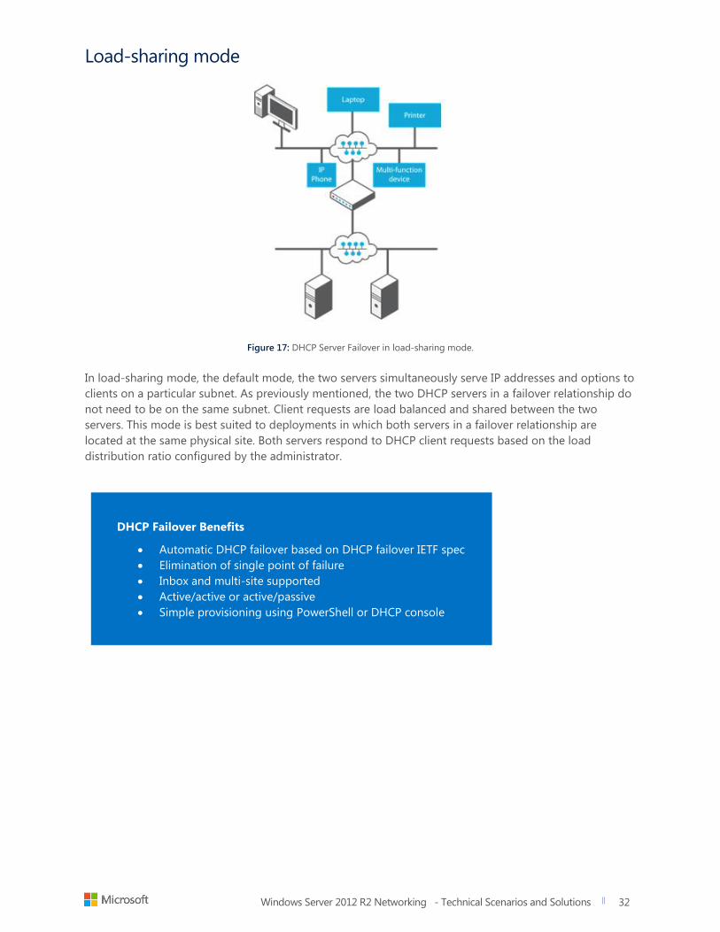
Load-sharing mode
Figure 17: DHCP Server Failover in load-sharing mode.
In load-sharing mode, the default mode, the two servers simultaneously serve IP addresses and options to
clients on a particular subnet. As previously mentioned, the two DHCP servers in a failover relationship do
not need to be on the same subnet. Client requests are load balanced and shared between the two
servers. This mode is best suited to deployments in which both servers in a failover relationship are
located at the same physical site. Both servers respond to DHCP client requests based on the load
distribution ratio configured by the administrator.
DHCP Failover Benefits
Automatic DHCP failover based on DHCP failover IETF spec
Elimination of single point of failure
Inbox and multi-site supported
Active/active or active/passive
Simple provisioning using PowerShell or DHCP console
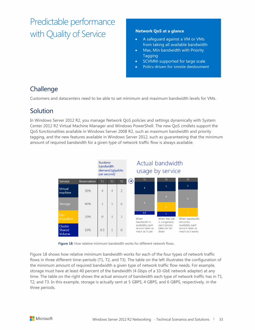
Windows Server 2012 R2 Networking - Technical Scenarios and Solutions
title of document
33
33
Predictable performance
with Quality of Service
Challenge
Customers and datacenters need to be able to set minimum and maximum bandwidth levels for VMs.
Solution
In Windows Server 2012 R2, you manage Network QoS policies and settings dynamically with System
Center 2012 R2 Virtual Machine Manager and Windows PowerShell. The new QoS cmdlets support the
QoS functionalities available in Windows Server 2008 R2, such as maximum bandwidth and priority
tagging, and the new features available in Windows Server 2012, such as guaranteeing that the minimum
amount of required bandwidth for a given type of network traffic flow is always available.
Figure 18: How relative minimum bandwidth works for different network flows.
Figure 18 shows how relative minimum bandwidth works for each of the four types of network traffic
flows in three different time-periods (T1, T2, and T3). The table on the left illustrates the configuration of
the minimum amount of required bandwidth a given type of network traffic flow needs. For example,
storage must have at least 40 percent of the bandwidth (4 Gbps of a 10-GbE network adapter) at any
time. The table on the right shows the actual amount of bandwidth each type of network traffic has in T1,
T2, and T3. In this example, storage is actually sent at 5 GBPS, 4 GBPS, and 6 GBPS, respectively, in the
three periods.
Network QoS at a glance
A safeguard against a VM or VMs
from taking all available bandwidth
Max, Min bandwidth with Priority
Tagging
SCVMM-supported for large scale
Policy driven for simple deployment
Windows Server 2012 R2 Networking - Technical Scenarios and Solutions
title of document
34
34
Why this matters
QoS minimum bandwidth benefits vary
from public cloud hosting providers to
enterprises. Most hosting providers and
enterprises today use a dedicated
network adapter and a dedicated
network for a specific type of workloads
such as storage or live migration to help
achieve network performance isolation
on a server running Hyper-V.
Benefits for public cloud hosting providers Host customers on a server running Hyper-V while
still providing a certain level of performance based
on SLAs.
Help ensure that customers won’t be affected or
compromised by other customers on their shared
infrastructure, which includes computing, storage,
and network resources.
Benefits for enterprises Run multiple application servers on a server running
Hyper-V. Each application server delivers
predictable performance, eliminating the fear of
virtualization due to lack of performance
predictability.
Virtualize busy SQL databases and ensure that they
get the bandwidth they need.
Sandbox their applications and provide different
SLAs/pricing depending on bandwidth guarantees
(applies to customers and hosters).
Benefits for Customer's SLA compliancy Help guarantee predictable network performance
and fair sharing during congestion
Support bandwidth floors and bandwidth caps
Help enforce customer SLAs and maximum pricing
caps
Set QoS for virtual machine or traffic type
Use software built into Windows Server 2012 R2 or
hardware capable of Data Center Bridging (DCB) to
assign minimum QoS settings
Support dynamic change of QoS settings through
PowerShell without any downtime
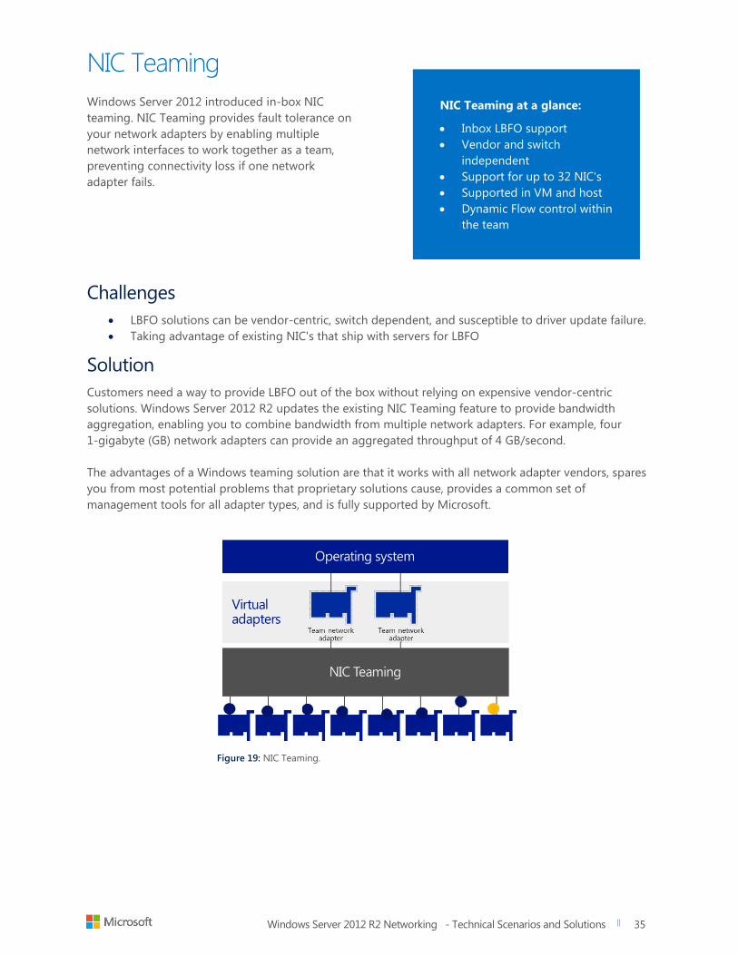
Windows Server 2012 R2 Networking - Technical Scenarios and Solutions
title of document
35
35
NIC Teaming
Windows Server 2012 introduced in-box NIC
teaming. NIC Teaming provides fault tolerance on
your network adapters by enabling multiple
network interfaces to work together as a team,
preventing connectivity loss if one network
adapter fails.
Challenges
LBFO solutions can be vendor-centric, switch dependent, and susceptible to driver update failure.
Taking advantage of existing NIC's that ship with servers for LBFO
Solution
Customers need a way to provide LBFO out of the box without relying on expensive vendor-centric
solutions. Windows Server 2012 R2 updates the existing NIC Teaming feature to provide bandwidth
aggregation, enabling you to combine bandwidth from multiple network adapters. For example, four
1-gigabyte (GB) network adapters can provide an aggregated throughput of 4 GB/second.
The advantages of a Windows teaming solution are that it works with all network adapter vendors, spares
you from most potential problems that proprietary solutions cause, provides a common set of
management tools for all adapter types, and is fully supported by Microsoft.
Figure 19: NIC Teaming.
NIC Teaming at a glance:
Inbox LBFO support
Vendor and switch
independent
Support for up to 32 NIC's
Supported in VM and host
Dynamic Flow control within
the team
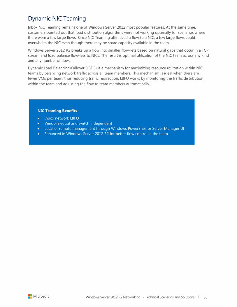
Windows Server 2012 R2 Networking - Technical Scenarios and Solutions
title of document
36
36
Dynamic NIC Teaming
Inbox NIC Teaming remains one of Windows Server 2012 most popular features. At the same time,
customers pointed out that load distribution algorithms were not working optimally for scenarios where
there were a few large flows. Since NIC Teaming affinitized a flow to a NIC, a few large flows could
overwhelm the NIC even though there may be spare capacity available in the team.
Windows Server 2012 R2 breaks up a flow into smaller flow-lets based on natural gaps that occur in a TCP
stream and load balance flow-lets to NICs. The result is optimal utilization of the NIC team across any kind
and any number of flows.
Dynamic Load Balancing/Failover (LBFO) is a mechanism for maximizing resource utilization within NIC
teams by balancing network traffic across all team members. This mechanism is ideal when there are
fewer VMs per team, thus reducing traffic redirection. LBFO works by monitoring the traffic distribution
within the team and adjusting the flow to team members automatically.
NIC Teaming Benefits
Inbox network LBFO
Vendor neutral and switch independent
Local or remote management through Windows PowerShell or Server Manager UI
Enhanced in Windows Server 2012 R2 for better flow control in the team
Windows Server 2012 R2 Networking - Technical Scenarios and Solutions
title of document
37
37
Customers want to get the best performance out of the hardware they have regardless of whether they
are using industry-standard hardware or high-end hardware that they have already invested in. Some of
the more common challenges they encounter include the following:
Limitations in network bandwidth
Limitations in the processing power
Windows Server 2012 R2 addresses these issues with the following features:
Virtual Receive Side Scaling (vRSS)
Single Root IO Virtualization (SR-IOV)
SMB Direct (RDMA)
Dynamic VMQ
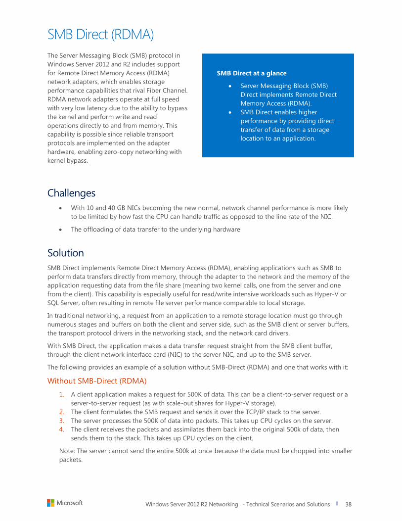
Windows Server 2012 R2 Networking - Technical Scenarios and Solutions
title of document
38
38
SMB Direct (RDMA)
The Server Messaging Block (SMB) protocol in
Windows Server 2012 and R2 includes support
for Remote Direct Memory Access (RDMA)
network adapters, which enables storage
performance capabilities that rival Fiber Channel.
RDMA network adapters operate at full speed
with very low latency due to the ability to bypass
the kernel and perform write and read
operations directly to and from memory. This
capability is possible since reliable transport
protocols are implemented on the adapter
hardware, enabling zero-copy networking with
kernel bypass.
Challenges
With 10 and 40 GB NICs becoming the new normal, network channel performance is more likely
to be limited by how fast the CPU can handle traffic as opposed to the line rate of the NIC.
The offloading of data transfer to the underlying hardware
Solution
SMB Direct implements Remote Direct Memory Access (RDMA), enabling applications such as SMB to
perform data transfers directly from memory, through the adapter to the network and the memory of the
application requesting data from the file share (meaning two kernel calls, one from the server and one
from the client). This capability is especially useful for read/write intensive workloads such as Hyper-V or
SQL Server, often resulting in remote file server performance comparable to local storage.
In traditional networking, a request from an application to a remote storage location must go through
numerous stages and buffers on both the client and server side, such as the SMB client or server buffers,
the transport protocol drivers in the networking stack, and the network card drivers.
With SMB Direct, the application makes a data transfer request straight from the SMB client buffer,
through the client network interface card (NIC) to the server NIC, and up to the SMB server.
The following provides an example of a solution without SMB-Direct (RDMA) and one that works with it:
Without SMB-Direct (RDMA)
1. A client application makes a request for 500K of data. This can be a client-to-server request or a
server-to-server request (as with scale-out shares for Hyper-V storage).
2. The client formulates the SMB request and sends it over the TCP/IP stack to the server.
3. The server processes the 500K of data into packets. This takes up CPU cycles on the server.
4. The client receives the packets and assimilates them back into the original 500k of data, then
sends them to the stack. This takes up CPU cycles on the client.
Note: The server cannot send the entire 500k at once because the data must be chopped into smaller
packets.
SMB Direct at a glance
Server Messaging Block (SMB)
Direct implements Remote Direct
Memory Access (RDMA).
SMB Direct enables higher
performance by providing direct
transfer of data from a storage
location to an application.

Windows Server 2012 R2 Networking - Technical Scenarios and Solutions
title of document
39
39
Figure 20: A client and server example without SMB-Direct and RDMA.
When using multiple NICs to handle many IO intensive operations, the CPU can become bottlenecked
while performing this kernel mode activity repeatedly. The more CPU time that is spent on processing
network packets, the less CPU time is available for other things such as database requests and VM
workloads.
With SMB-Direct / RDMA
Through work with partners and vendors, Microsoft has brought to Windows Server 2012 R2 a class of
specialized NICs to support high-speed data transfers. These NICs have a better CPU and support RDMA
so that they can transfer data between them without involving the host CPU.
In the SMB-Direct (RDMA) example below:
1. The client requests the same 500K of data.
2. The SMB-Direct transport driver locates a place in memory where that data should reside and
registers it on behalf of the NIC.
3. An RDMA request is sent to the server requesting to read the 500K of data directly into client
memory.
4. The client application and server transfer data directly, memory-to-memory, outside the packet
level constraints incurred when normal peer-to-peer networking happens over TCP/IP.
5. The two NIC or teams perform the transfer without any outside CPU dependencies and overhead.
SMB Direct is extremely fast. In testing, 1-2 millisecond latencies were seen when doing transfers. This is
almost the speed of using local storage. Support for Infiniband, RoCE and iWARP network interfaces also
helps further increase speed.
Windows Server 2012 R2 Networking - Technical Scenarios and Solutions
title of document
40
40
Figure 21: A client and server example with SMB-Direct and RDMA.
In traditional networking, a request from an application
to a remote storage location must go through numerous
stages and buffers on both the client and server side,
such as the SMB client or server buffers, the transport
protocol drivers in the networking stack, and the
network card drivers
With SMB Direct, the application makes a data transfer
request straight from the SMB client buffer, through the
client network interface card (NIC) to the server NIC, and
over to the SMB server. This change provides the
application with access to remote storage at the same
speed as local storage.
With iWarp and Infiniband networking technologies, this
change can deliver transfer rates equivalent to 50Gbps
on a single 56 GB NIC. SMB Direct can enhance transfer
rates and increase the reliability of network paths
through direct compatibility with SMB Multichannel as
part of SMB 3.0.
Did you know?
Mellanox and Intel are some
of the vendors that make
RDMA capable NICs
RDMA will become defacto
in 10gb and 40Gb NICs
SMB-Direct Benefits
Higher performance and lower latency through CPU offloading
High-speed network utilization (Inlcuding InfiniBand and iWARP)
Remote storage at the speed of direct storage
Transfer rate of approximately50 Gbps on a single NIC port
Compatibility with SMB Multichannel for load balancing and failover
Windows Server 2012 R2 Networking - Technical Scenarios and Solutions
title of document
41
41
Virtual Receive Side
Scaling (vRSS)
Windows Server 2012 first introduced Receive Side Scaling
(RSS) as a way to spread the CPU load of processing
network IO across all available CPU's. This was available for
the host, but not the VM's running on that host.
Virtual RSS (vRSS) in Windows Server 2012 R2 enables both
the host and the VM to use multiple cores, resulting in
bandwidth scaling characteristics that are similar to what
RSS enables for large physical workloads. In test
environments with a simulated workload, vRSS enabled a
VM to meet a near line rate on a 10Gbps NIC compared to
~5.5Gbps without this capability.
Challenges
RSS capabilities need to be made available on VM and the Hyper-V host
Solution
Windows Server 2012 R2 introduces Virtual RSS
(vRSS), a feature that makes RSS available to the
host and to the VMs on that host. This change
substantially increases the networking capabilities
of virtual machines on a host by eliminating
multiple bottlenecks and enabling use of all
resources available to the VM. vRSS gives near line
rate both to the Hyper-V host and VM, using
existing hardware to helps exceed the current
limitation of approximately 4.5Gbs experienced
with a 10Gb NIC connected to a VM.
vRSS works by scaling a VM's receive-side traffic
to multiple virtual processors, so that the
incoming traffic spreads over the total number of
cores available to that VM. With vRSS, send-side
traffic from a VM is also distributed over multiple
processors, so that virtual switch processing does
not generate bottlenecks on a single physical
processor when sending large amounts of
outgoing traffic. This is all possible with any NICs
that support SR-IOV RSS.
Customer Benefits
vRSS scales a VM's receive
side traffic to multiple
virtual processors
Near line rate network
speeds to a VM on existing
hardware
Excellent performance on
network intensive VM's
Up to 100 GPS speed
possible for a VM
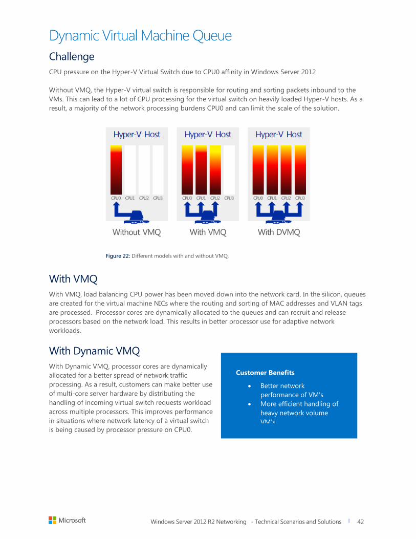
Windows Server 2012 R2 Networking - Technical Scenarios and Solutions
title of document
42
42
Dynamic Virtual Machine Queue
Challenge
CPU pressure on the Hyper-V Virtual Switch due to CPU0 affinity in Windows Server 2012
Without VMQ, the Hyper-V virtual switch is responsible for routing and sorting packets inbound to the
VMs. This can lead to a lot of CPU processing for the virtual switch on heavily loaded Hyper-V hosts. As a
result, a majority of the network processing burdens CPU0 and can limit the scale of the solution.
Figure 22: Different models with and without VMQ.
With VMQ
With VMQ, load balancing CPU power has been moved down into the network card. In the silicon, queues
are created for the virtual machine NICs where the routing and sorting of MAC addresses and VLAN tags
are processed. Processor cores are dynamically allocated to the queues and can recruit and release
processors based on the network load. This results in better processor use for adaptive network
workloads.
With Dynamic VMQ
With Dynamic VMQ, processor cores are dynamically
allocated for a better spread of network traffic
processing. As a result, customers can make better use
of multi-core server hardware by distributing the
handling of incoming virtual switch requests workload
across multiple processors. This improves performance
in situations where network latency of a virtual switch
is being caused by processor pressure on CPU0.
Customer Benefits
Better network
performance of VM's
More efficient handling of
heavy network volume
VM's
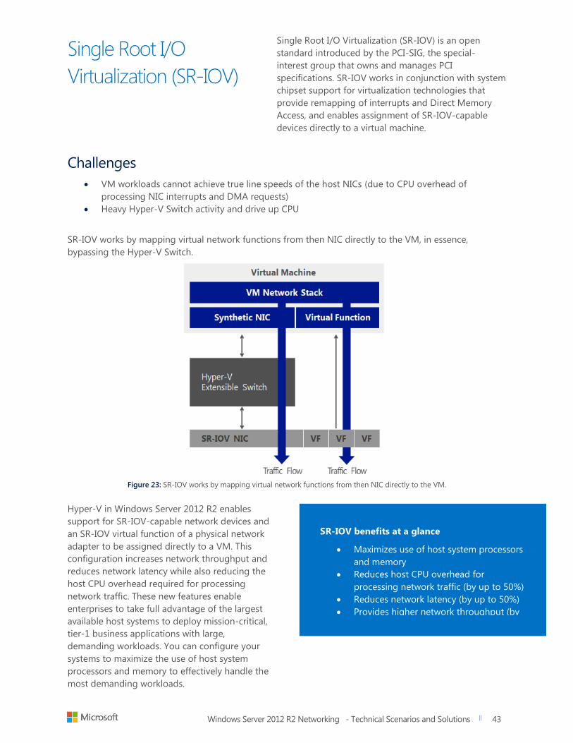
Windows Server 2012 R2 Networking - Technical Scenarios and Solutions
title of document
43
43
Single Root I/O
Virtualization (SR-IOV)
Single Root I/O Virtualization (SR-IOV) is an open
standard introduced by the PCI-SIG, the special-
interest group that owns and manages PCI
specifications. SR-IOV works in conjunction with system
chipset support for virtualization technologies that
provide remapping of interrupts and Direct Memory
Access, and enables assignment of SR-IOV-capable
devices directly to a virtual machine.
Challenges
VM workloads cannot achieve true line speeds of the host NICs (due to CPU overhead of
processing NIC interrupts and DMA requests)
Heavy Hyper-V Switch activity and drive up CPU
SR-IOV works by mapping virtual network functions from then NIC directly to the VM, in essence,
bypassing the Hyper-V Switch.
Figure 23: SR-IOV works by mapping virtual network functions from then NIC directly to the VM.
Hyper-V in Windows Server 2012 R2 enables
support for SR-IOV-capable network devices and
an SR-IOV virtual function of a physical network
adapter to be assigned directly to a VM. This
configuration increases network throughput and
reduces network latency while also reducing the
host CPU overhead required for processing
network traffic. These new features enable
enterprises to take full advantage of the largest
available host systems to deploy mission-critical,
tier-1 business applications with large,
demanding workloads. You can configure your
systems to maximize the use of host system
processors and memory to effectively handle the
most demanding workloads.
SR-IOV benefits at a glance
Maximizes use of host system processors
and memory
Reduces host CPU overhead for
processing network traffic (by up to 50%)
Reduces network latency (by up to 50%)
Provides higher network throughput (by
up to 30%)
Windows Server 2012 R2 Networking - Technical Scenarios and Solutions
title of document
44
44
Manageability is one of the most important challenges customers face. There are many types of
management features that IT staffs seek to simplify their lives. For example, having the ability to automate
regular tasks or control the entire IP address infrastructure, no matter the size of your organization. There’s
also having the ability to maximize performance on a multi-site environment or track resource usage and
build chargeback/show-back solutions.
Windows Server 2012 R2 greatly enhances manageability of enterprise network resources and assets with
tools and features such as the following:
IP Address Management (IPAM)
Resource Metering
Network monitoring using System Center 2012 Operations Manager
Management with System Center 2012 Virtual Machine Manager
Windows PowerShell
Windows Server 2012 R2 Networking - Technical Scenarios and Solutions
title of document
45
45
Windows Server 2012
R2 IP Address
Management (IPAM)
Challenges
Difficulties with centralized management of entire IP address space
Difficulties with virtualized networks
Manual, DCHP and DNS administration creates high overhead when each client has their own
services
Solution
Windows Server 2012 introduced IPAM, which provides centralized tracking and administration of IP
addresses (physical and virtual), DHCP and DNS, along with rich PowerShell automation. In Windows
Server 2012 R2, IPAM enables network administrators to fully streamline IP address space administration
of both physical (fabric) and virtual (tenant) networks. The integration between IPAM and SCVMM in the
R2 release provides end-to-end IP address space automation for Microsoft-powered cloud networks. A
single instance of IPAM can detect and prevent IP address space conflicts, duplicates, and overlaps across
multiple instances of SCVMM deployed in a large datacenter or across datacenters.
Fine-grained administrative control
As customer clouds grow in size and deployment, there is a need for IPAM to enable appropriate
privileges for the different scopes. With the R2 release, IPAM can now enable granular role-based access
control (RBAC) and delegated administration. System and network administrators can use IPAM to define
the roles (collection of administrative operations and whether they can be delegated); access scopes
(administrative domains in IPAM to determine the entities that the user has access to); and access policies
(combines a role with an access scope to assign permission to a user or group). Such capabilities give
administrators the needed flexibility to confidently administer their large cloud environments.
Highly scalable and customizable
Automation is key to attain cloud scale, and IPAM is no exception. IPAM provides a comprehensive set of
PowerShell cmdlets to facilitate the operations described earlier and to enable integration with various
other systems in the network. In addition, SQL Server is now supported as an optional backend for IPAM
database to enable large scale solutions.
Windows Server 2012 R2 IPAM at glance
Enterprise Level IP address space and
Infrastructure management and
Monitoring
Support for a centralized or distributed
model
Manual or automatic discovery of DHCP,
DNS, and domain controllers
Physical and Virtual address space and
integration with SCVMM
Integration with SCVMM network
configuration and deployment
AD site integration for large scale role-
based access and control
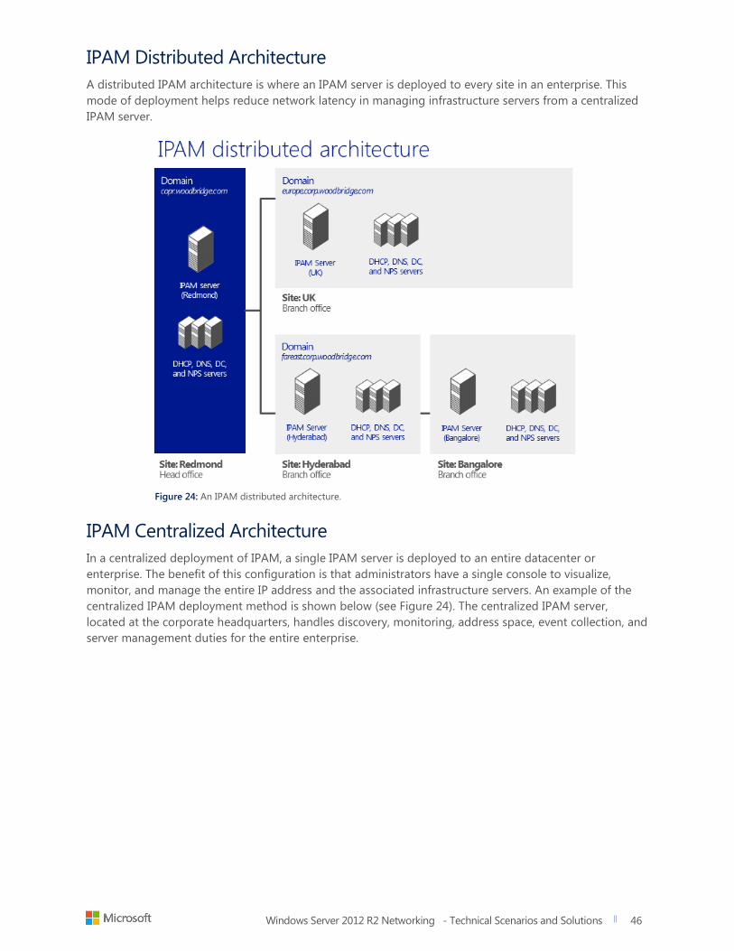
Windows Server 2012 R2 Networking - Technical Scenarios and Solutions
title of document
46
46
IPAM Distributed Architecture
A distributed IPAM architecture is where an IPAM server is deployed to every site in an enterprise. This
mode of deployment helps reduce network latency in managing infrastructure servers from a centralized
IPAM server.
Figure 24: An IPAM distributed architecture.
IPAM Centralized Architecture
In a centralized deployment of IPAM, a single IPAM server is deployed to an entire datacenter or
enterprise. The benefit of this configuration is that administrators have a single console to visualize,
monitor, and manage the entire IP address and the associated infrastructure servers. An example of the
centralized IPAM deployment method is shown below (see Figure 24). The centralized IPAM server,
located at the corporate headquarters, handles discovery, monitoring, address space, event collection, and
server management duties for the entire enterprise.
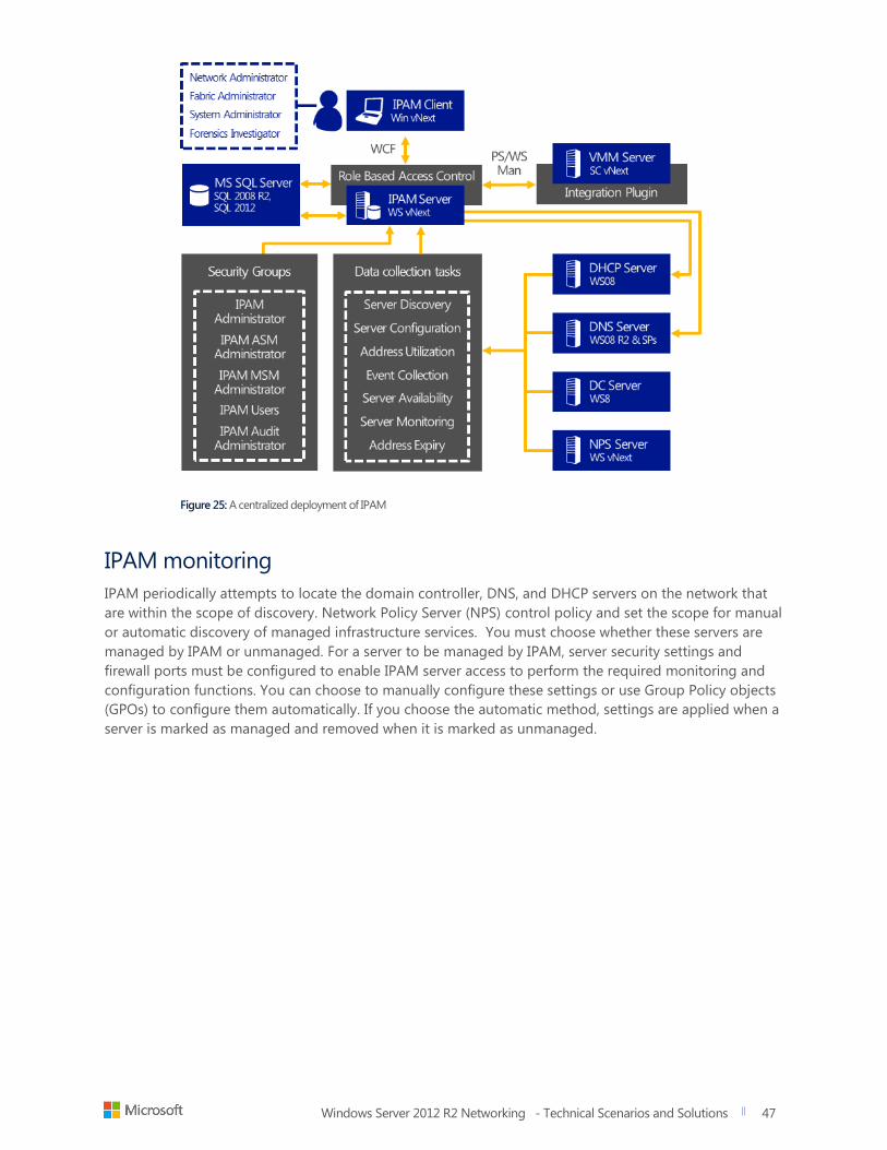
Windows Server 2012 R2 Networking - Technical Scenarios and Solutions
title of document
47
47
Figure 25: A centralized deployment of IPAM
IPAM monitoring
IPAM periodically attempts to locate the domain controller, DNS, and DHCP servers on the network that
are within the scope of discovery. Network Policy Server (NPS) control policy and set the scope for manual
or automatic discovery of managed infrastructure services. You must choose whether these servers are
managed by IPAM or unmanaged. For a server to be managed by IPAM, server security settings and
firewall ports must be configured to enable IPAM server access to perform the required monitoring and
configuration functions. You can choose to manually configure these settings or use Group Policy objects
(GPOs) to configure them automatically. If you choose the automatic method, settings are applied when a
server is marked as managed and removed when it is marked as unmanaged.
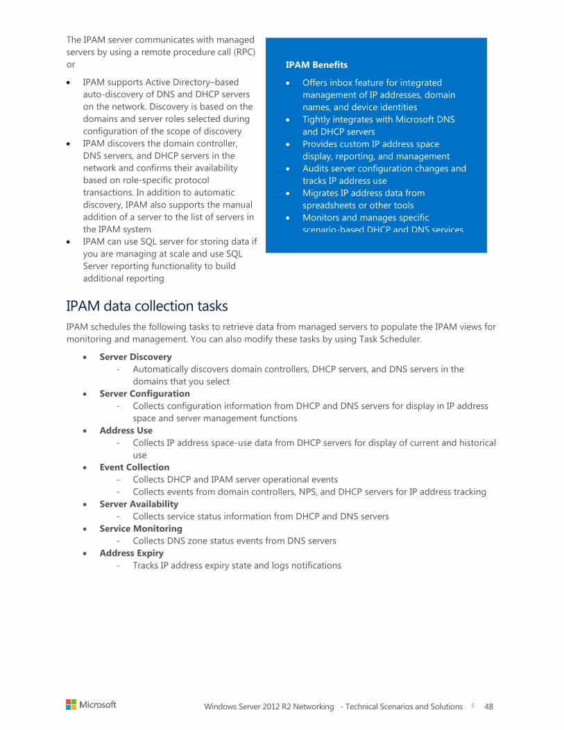
Windows Server 2012 R2 Networking - Technical Scenarios and Solutions
title of document
48
48
The IPAM server communicates with managed
servers by using a remote procedure call (RPC)
or
IPAM supports Active Directory–based
auto-discovery of DNS and DHCP servers
on the network. Discovery is based on the
domains and server roles selected during
configuration of the scope of discovery
IPAM discovers the domain controller,
DNS servers, and DHCP servers in the
network and confirms their availability
based on role-specific protocol
transactions. In addition to automatic
discovery, IPAM also supports the manual
addition of a server to the list of servers in
the IPAM system
IPAM can use SQL server for storing data if
you are managing at scale and use SQL
Server reporting functionality to build
additional reporting
IPAM data collection tasks
IPAM schedules the following tasks to retrieve data from managed servers to populate the IPAM views for
monitoring and management. You can also modify these tasks by using Task Scheduler.
Server Discovery
- Automatically discovers domain controllers, DHCP servers, and DNS servers in the
domains that you select
Server Configuration
- Collects configuration information from DHCP and DNS servers for display in IP address
space and server management functions
Address Use
- Collects IP address space-use data from DHCP servers for display of current and historical
use
Event Collection
- Collects DHCP and IPAM server operational events
- Collects events from domain controllers, NPS, and DHCP servers for IP address tracking
Server Availability
- Collects service status information from DHCP and DNS servers
Service Monitoring
- Collects DNS zone status events from DNS servers
Address Expiry
- Tracks IP address expiry state and logs notifications
IPAM Benefits
Offers inbox feature for integrated
management of IP addresses, domain
names, and device identities
Tightly integrates with Microsoft DNS
and DHCP servers
Provides custom IP address space
display, reporting, and management
Audits server configuration changes and
tracks IP address use
Migrates IP address data from
spreadsheets or other tools
Monitors and manages specific
scenario-based DHCP and DNS services
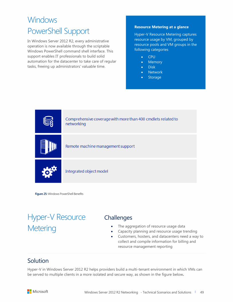
Windows Server 2012 R2 Networking - Technical Scenarios and Solutions
title of document
49
49
Windows
PowerShell Support In Windows Server 2012 R2, every administrative
operation is now available through the scriptable
Windows PowerShell command shell interface. This
support enables IT professionals to build solid
automation for the datacenter to take care of regular
tasks, freeing up administrators' valuable time.
Figure 25: Windows PowerShell Benefits
Hyper-V Resource
Metering
Challenges
The aggregation of resource usage data
Capacity planning and resource usage trending
Customers, hosters, and datacenters need a way to
collect and compile information for billing and
resource management reporting
Solution
Hyper-V in Windows Server 2012 R2 helps providers build a multi-tenant environment in which VMs can
be served to multiple clients in a more isolated and secure way, as shown in the figure below.
Resource Metering at a glance
Hyper-V Resource Metering captures
resource usage by VM, grouped by
resource pools and VM groups in the
following categories
CPU
Memory
Disk
Network
Storage
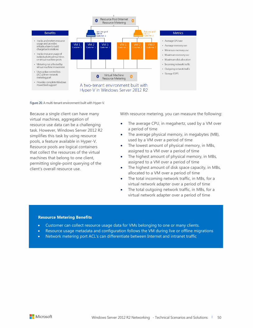
Windows Server 2012 R2 Networking - Technical Scenarios and Solutions
title of document
50
50
Figure 26: A multi-tenant environment built with Hyper-V.
Because a single client can have many
virtual machines, aggregation of
resource use data can be a challenging
task. However, Windows Server 2012 R2
simplifies this task by using resource
pools, a feature available in Hyper-V.
Resource pools are logical containers
that collect the resources of the virtual
machines that belong to one client,
permitting single-point querying of the
client’s overall resource use.
With resource metering, you can measure the following:
The average CPU, in megahertz, used by a VM over
a period of time
The average physical memory, in megabytes (MB),
used by a VM over a period of time
The lowest amount of physical memory, in MBs,
assigned to a VM over a period of time
The highest amount of physical memory, in MBs,
assigned to a VM over a period of time
The highest amount of disk space capacity, in MBs,
allocated to a VM over a period of time
The total incoming network traffic, in MBs, for a
virtual network adapter over a period of time
The total outgoing network traffic, in MBs, for a
virtual network adapter over a period of time
Resource Metering Benefits
Customer can collect resource usage data for VMs belonging to one or many clients.
Resource usage metadata and configuration follows the VM during live or offline migrations
Network metering port ACL's can differentiate between Internet and intranet traffic
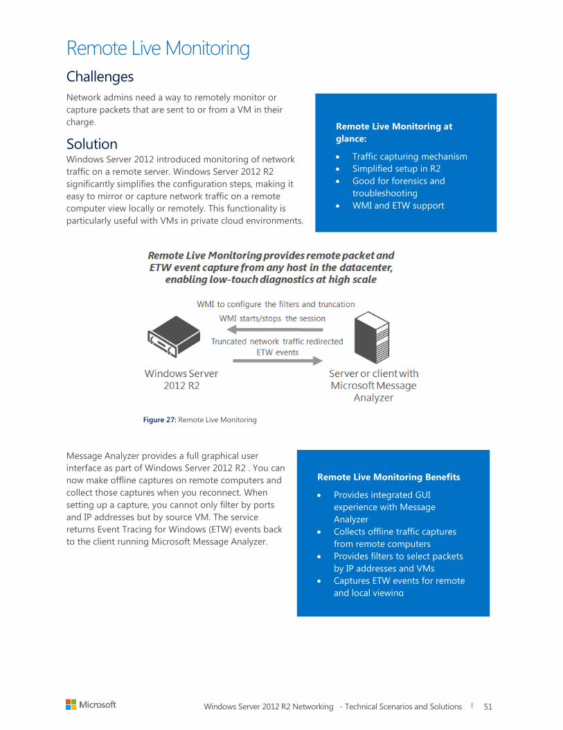
Windows Server 2012 R2 Networking - Technical Scenarios and Solutions
title of document
51
51
Remote Live Monitoring
Challenges
Network admins need a way to remotely monitor or
capture packets that are sent to or from a VM in their
charge.
Solution Windows Server 2012 introduced monitoring of network
traffic on a remote server. Windows Server 2012 R2
significantly simplifies the configuration steps, making it
easy to mirror or capture network traffic on a remote
computer view locally or remotely. This functionality is
particularly useful with VMs in private cloud environments.
Figure 27: Remote Live Monitoring
Message Analyzer provides a full graphical user
interface as part of Windows Server 2012 R2 . You can
now make offline captures on remote computers and
collect those captures when you reconnect. When
setting up a capture, you cannot only filter by ports
and IP addresses but by source VM. The service
returns Event Tracing for Windows (ETW) events back
to the client running Microsoft Message Analyzer.
Remote Live Monitoring at
glance:
Traffic capturing mechanism
Simplified setup in R2
Good for forensics and
troubleshooting
WMI and ETW support
Remote Live Monitoring Benefits
Provides integrated GUI
experience with Message
Analyzer
Collects offline traffic captures
from remote computers
Provides filters to select packets
by IP addresses and VMs
Captures ETW events for remote
and local viewing
Windows Server 2012 R2 Networking - Technical Scenarios and Solutions
title of document
52
52
Networking and isolation
in the Private Cloud using
System Center 2012
Challenges
Virtualized Network setup and Management is difficult to manually manage as scale
The application of policy to hosts and VMs is time consuming and manual at scale
Customers and cloud administrators need a way to manage virtualized networks at scale while delivering
the levels of isolation and automation required for customers specific needs. They also need to take
advantage of existing network appliances with a set of providers that can connect to load balancers,
switch extension managers, and network virtualization gateways. This functionality lays the groundwork
for load balancing clouds, logical networks, and host groups the same way you would a physical network.
Datacenters need increased visibility into the network infrastructure (logical and physical). This helps to
identify service availability issues and responsiveness/performance issues, which are caused by the
underlying network. These tools need to be centrally available to the Network Monitoring Team.
System Center 2012 at a glance
Manages switch extensions
Provides Inbox NV Gateways
Offers Load balancer plugins from
a centralized location
Applies policies to hosts and VMs
in a consistent fashion
Windows Server 2012 R2 Networking - Technical Scenarios and Solutions
title of document
53
53
System Center 2012 R2 Virtual
Machine Manager System Center 2012 R2 Virtual Machine Manager
(SCVMM) is a component of the System Center 2012 R2
suite. It is used to centrally manage compute, storage and
networking resources in your datacenter or private cloud.
A hoster can implement SCVMM 2012 R2 to manage all
of their Hyper-V, VMWare, Citrix hosts, and VMs.
Challenges
Management overhead grows exponentially with every tenant and cloud environment added to the
infrastructure
Without automation, manual configurations and deployments of virtual networks is difficult at large
scale, especially for multi-vendor clouds
Solution
With SCVMM 2012 R2, you can configure virtual networks and virtual switches, and push those
configurations out to any number of hosts. SCVMM 2012 R2 also helps you manage how logical networks
overlay the physical network fabric of the datacenter through advanced tools and consoles used for setup
and deployment of NVGRE, NAT, and BGP policies.
In addition, SCVMM 2012 R2 includes gateway services, such as the Multi-tenant VPN gateway (discussed
earlier). Repeatable virtual updates and configuration changes are easy to deploy to any number of
Hyper-V hosts. This configuration data stays with the VM even when if it is migrated to another host in
the cloud infrastructure.
Keep in mind that SCVMM 2012 R2 is not just for Hyper-V. It can centrally manage your entire cloud
infrastructure of Hyper-V, VMWare, or Citrix servers. This includes the centralized management and
provisioning of the VMs on those hosts. For more on System Center 2012 R2 Virtual Machine Manager,
see: http://blogs.technet.com/b/scvmm/.
SCVMM 2012 R2 at a glance:
Policy-based deployment of
virtual networks to scale
Cloud level management and
monitoring for all aspects of
the cloud
Automated VM Provisioning
and online cloning
Highly available with Failover
Clustering

Windows Server 2012 R2 Networking - Technical Scenarios and Solutions
title of document
54
54
Virtual Network Isolation
In SCVMM 2012 R2, you can isolate VM Networks
using either traditional VLAN/PVLANS or, if you
are using Windows Server 2012 R2 as your host
operating system, you can choose to implement
SDN to scale with SCVMM 2012 R2. The latter
option addresses the scale limitations associated
with a traditional VLANs solution as well as
enables tenants to “bring their own network” or
otherwise extend their network into your
environment. The diagram at the link below shows
each of these options and acts as a reference for
the detailed discussion that follows.
Private Virtual LANs (PVLANS) are often used by
Service Providers (Hosters) to work around the
scale limitations of VLANS, essentially enabling
network administrators to divide a VLAN into a
number of separate and isolated sub-networks
which can then be allocated to individual
customers (tenants). PVLANs share the allocated
IP subnet to the parent VLAN, as you might
expect. From a security perspective, although
hosts connected to different PVLANs still belong
to the same IP subnet, they require a router to
communicate with each other and with resources
on any other network.
A PVLAN consists of a Primary and Secondary
VLAN pair, with each capable of configured in one
of three modes as shown below (see Figure 28). In
Promiscuous mode, hosts are on the primary
VLAN and are able to communicate directly with
resources on the primary VLAN and also the
secondary VLAN. In a Community mode, the
secondary VLAN represents a community. Direct
communication is permitted only with hosts in the
same community and those that are connected to
the Primary PVLAN in promiscuous mode. Isolated
PVLANs only permit direct communication with
promiscuous resources that exist in the Primary
PVLAN.
Figure 28: A PVLAN consists of a Primary and Secondary VLAN pair.
SCVMM 2012 R2 only supports isolated mode (as
described above) and has no concept of primary
(promiscuous) or community modes. What this
means in practice is that a VM connected to a
PVLAN in this release is completely isolated from
any other resources on the network. The only
device it can directly communicate with is the
default IP gateway. While this may feel like a
severe limitation, there are a number of scenarios
which work quite well in this configuration - the
most common example of which is Front End Web
Servers. In this specific scenario, all of the web
servers in a web farm are placed on a single
network subnet but are otherwise completely
isolated from each other. Here PVLANs help to
simplify management and improve overall
security.
SCVMM 2012 R2 builds on standard PVLAN
isolation by giving network administrators a
console for building the logical networks and
configuring abstraction of those networks over
the top of physical networks. With the ability to
create one or more private clouds, administrators
can now provide for the different networking
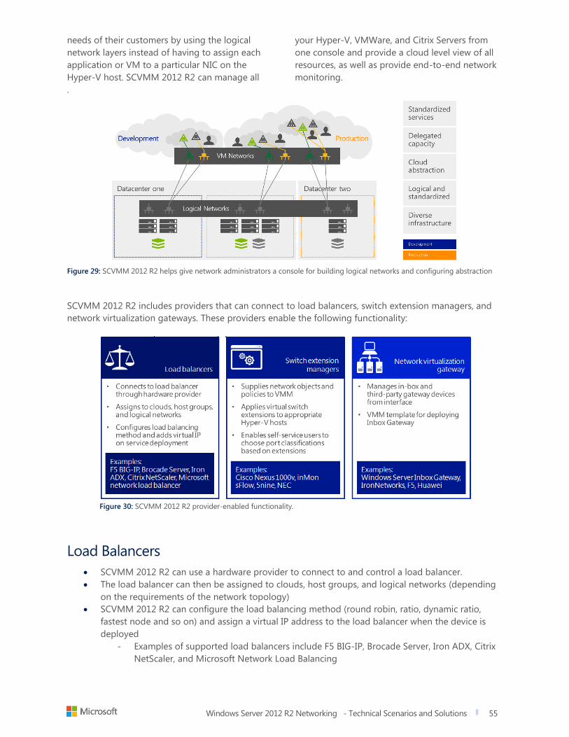
Windows Server 2012 R2 Networking - Technical Scenarios and Solutions
title of document
55
55
needs of their customers by using the logical
network layers instead of having to assign each
application or VM to a particular NIC on the
Hyper-V host. SCVMM 2012 R2 can manage all
your Hyper-V, VMWare, and Citrix Servers from
one console and provide a cloud level view of all
resources, as well as provide end-to-end network
monitoring.
.
Figure 29: SCVMM 2012 R2 helps give network administrators a console for building logical networks and configuring abstraction
SCVMM 2012 R2 includes providers that can connect to load balancers, switch extension managers, and
network virtualization gateways. These providers enable the following functionality:
Figure 30: SCVMM 2012 R2 provider-enabled functionality.
Load Balancers
SCVMM 2012 R2 can use a hardware provider to connect to and control a load balancer.
The load balancer can then be assigned to clouds, host groups, and logical networks (depending
on the requirements of the network topology)
SCVMM 2012 R2 can configure the load balancing method (round robin, ratio, dynamic ratio,
fastest node and so on) and assign a virtual IP address to the load balancer when the device is
deployed
- Examples of supported load balancers include F5 BIG-IP, Brocade Server, Iron ADX, Citrix
NetScaler, and Microsoft Network Load Balancing
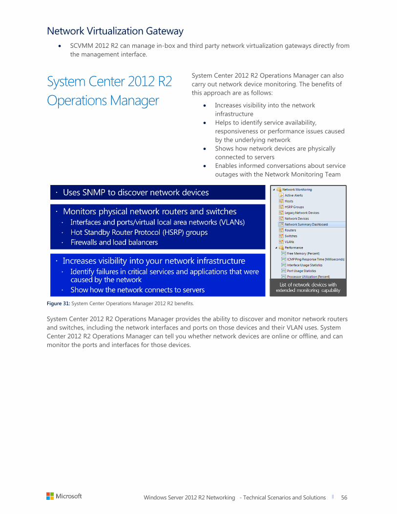
Windows Server 2012 R2 Networking - Technical Scenarios and Solutions
title of document
56
56
Network Virtualization Gateway
SCVMM 2012 R2 can manage in-box and third party network virtualization gateways directly from
the management interface.
System Center 2012 R2
Operations Manager
System Center 2012 R2 Operations Manager can also
carry out network device monitoring. The benefits of
this approach are as follows:
Increases visibility into the network
infrastructure
Helps to identify service availability,
responsiveness or performance issues caused
by the underlying network
Shows how network devices are physically
connected to servers
Enables informed conversations about service
outages with the Network Monitoring Team
Figure 31: System Center Operations Manager 2012 R2 benefits.
System Center 2012 R2 Operations Manager provides the ability to discover and monitor network routers
and switches, including the network interfaces and ports on those devices and their VLAN uses. System
Center 2012 R2 Operations Manager can tell you whether network devices are online or offline, and can
monitor the ports and interfaces for those devices.
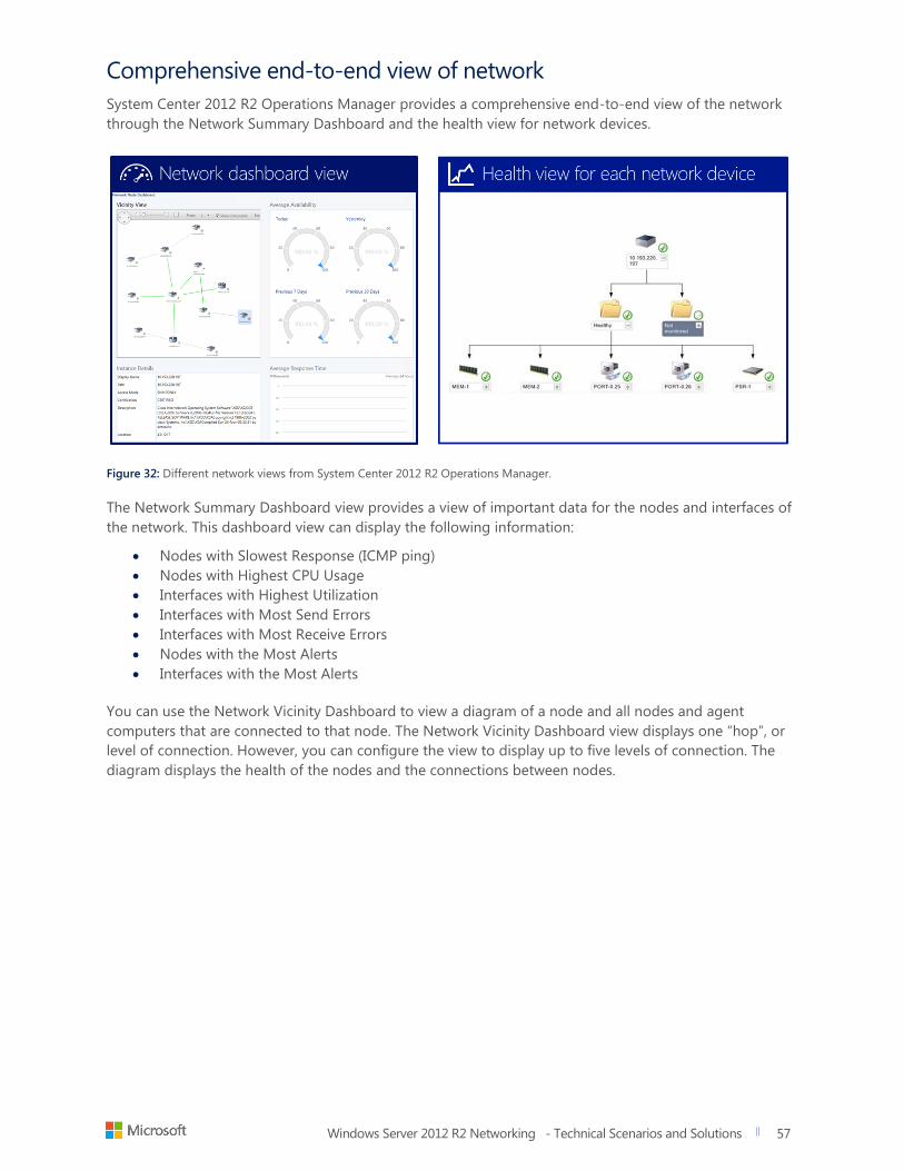
Windows Server 2012 R2 Networking - Technical Scenarios and Solutions
title of document
57
57
Comprehensive end-to-end view of network
System Center 2012 R2 Operations Manager provides a comprehensive end-to-end view of the network
through the Network Summary Dashboard and the health view for network devices.
Figure 32: Different network views from System Center 2012 R2 Operations Manager.
The Network Summary Dashboard view provides a view of important data for the nodes and interfaces of
the network. This dashboard view can display the following information:
Nodes with Slowest Response (ICMP ping)
Nodes with Highest CPU Usage
Interfaces with Highest Utilization
Interfaces with Most Send Errors
Interfaces with Most Receive Errors
Nodes with the Most Alerts
Interfaces with the Most Alerts
You can use the Network Vicinity Dashboard to view a diagram of a node and all nodes and agent
computers that are connected to that node. The Network Vicinity Dashboard view displays one “hop”, or
level of connection. However, you can configure the view to display up to five levels of connection. The
diagram displays the health of the nodes and the connections between nodes.
Windows Server 2012 R2 Networking - Technical Scenarios and Solutions
title of document
58
58
System Center 2012 R2 Customer Benefits
With System Center 2012 R2 Virtual Machine Manager, cloud administrators can enforce the
proper levels of isolation, even if the VM is or moved to a different host on a different network, or
to a different datacenter. SCVMM 2012 R2 also increases visibility into the network infrastructure
- Virtualization Gateway, switch extensions and load balancer providers help network
administrators make better use of their existing physical infrastructure appliances.
System Center 2012 R2 Operations Manager eliminates gaps in network device monitoring. If an
application becomes unavailable, you can use the end-to-end distributed view of the entire
network infrastructure to troubleshoot and resolve the issue effectively.
- System Center 2012 R2 Operations Manager helps to identify service availability,
responsiveness or performance issues caused by the underlying network
- System Center 2012 R2 Operations Manager shows how network devices are physically
connected to servers
- System Center 2012 R2 Operations Manager enables informed conversations about
service outages with the Network Monitoring Tea
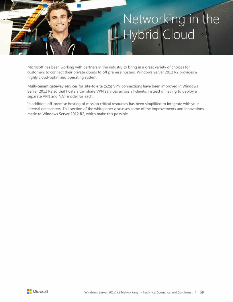
Windows Server 2012 R2 Networking - Technical Scenarios and Solutions
title of document
59
59
Microsoft has been working with partners in the industry to bring in a great variety of choices for
customers to connect their private clouds to off premise hosters. Windows Server 2012 R2 provides a
highly cloud-optimized operating system. Multi-tenant gateway services for site-to-site (S2S) VPN connections have been improved in Windows
Server 2012 R2 so that hosters can share VPN services across all clients, instead of having to deploy a
separate VPN and NAT model for each.
In addition, off-premise hosting of mission critical resources has been simplified to integrate with your
internal datacenters. This section of the whitepaper discusses some of the improvements and innovations
made to Windows Server 2012 R2, which make this possible.
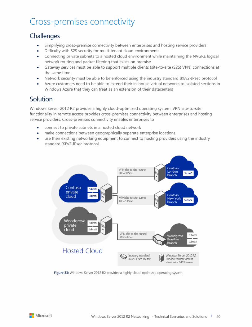
Windows Server 2012 R2 Networking - Technical Scenarios and Solutions
title of document
60
60
Cross-premises connectivity
Challenges
Simplifying cross-premise connectivity between enterprises and hosting service providers
Difficulty with S2S security for multi-tenant cloud environments
Connecting private subnets to a hosted cloud environment while maintaining the NVGRE logical
network routing and packet filtering that exists on premise
Gateway services must be able to support multiple clients (site-to-site (S2S) VPN) connections at
the same time
Network security must be able to be enforced using the industry standard IKEv2-IPsec protocol
Azure customers need to be able to extend their in-house virtual networks to isolated sections in
Windows Azure that they can treat as an extension of their datacenters
Solution
Windows Server 2012 R2 provides a highly cloud-optimized operating system. VPN site-to-site
functionality in remote access provides cross-premises connectivity between enterprises and hosting
service providers. Cross-premises connectivity enables enterprises to
connect to private subnets in a hosted cloud network
make connections between geographically separate enterprise locations.
use their existing networking equipment to connect to hosting providers using the industry
standard IKEv2-IPsec protocol.
Figure 33: Windows Server 2012 R2 provides a highly cloud-optimized operating system.
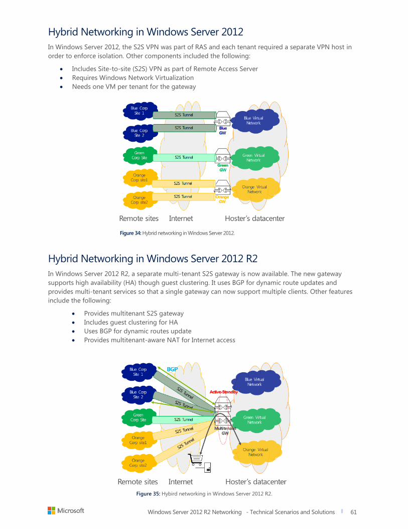
Windows Server 2012 R2 Networking - Technical Scenarios and Solutions
title of document
61
61
Hybrid Networking in Windows Server 2012
In Windows Server 2012, the S2S VPN was part of RAS and each tenant required a separate VPN host in
order to enforce isolation. Other components included the following:
Includes Site-to-site (S2S) VPN as part of Remote Access Server
Requires Windows Network Virtualization
Needs one VM per tenant for the gateway
Figure 34: Hybrid networking in Windows Server 2012.
Hybrid Networking in Windows Server 2012 R2
In Windows Server 2012 R2, a separate multi-tenant S2S gateway is now available. The new gateway
supports high availability (HA) though guest clustering. It uses BGP for dynamic route updates and
provides multi-tenant services so that a single gateway can now support multiple clients. Other features
include the following:
Provides multitenant S2S gateway
Includes guest clustering for HA
Uses BGP for dynamic routes update
Provides multitenant-aware NAT for Internet access
Figure 35: Hybird networking in Windows Server 2012 R2.
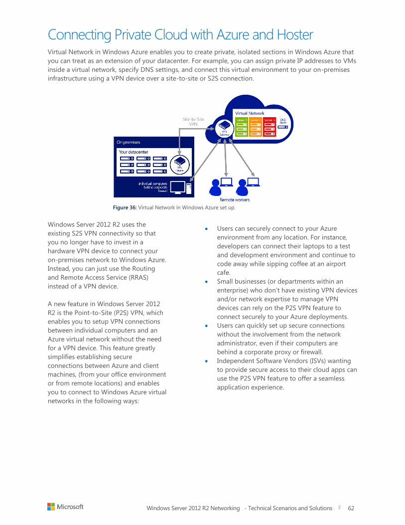
Windows Server 2012 R2 Networking - Technical Scenarios and Solutions
title of document
62
62
Connecting Private Cloud with Azure and Hoster Virtual Network in Windows Azure enables you to create private, isolated sections in Windows Azure that
you can treat as an extension of your datacenter. For example, you can assign private IP addresses to VMs
inside a virtual network, specify DNS settings, and connect this virtual environment to your on-premises
infrastructure using a VPN device over a site-to-site or S2S connection.
Figure 36: Virtual Network in Windows Azure set up.
Windows Server 2012 R2 uses the
existing S2S VPN connectivity so that
you no longer have to invest in a
hardware VPN device to connect your
on-premises network to Windows Azure.
Instead, you can just use the Routing
and Remote Access Service (RRAS)
instead of a VPN device.
A new feature in Windows Server 2012
R2 is the Point-to-Site (P2S) VPN, which
enables you to setup VPN connections
between individual computers and an
Azure virtual network without the need
for a VPN device. This feature greatly
simplifies establishing secure
connections between Azure and client
machines, (from your office environment
or from remote locations) and enables
you to connect to Windows Azure virtual
networks in the following ways:
Users can securely connect to your Azure
environment from any location. For instance,
developers can connect their laptops to a test
and development environment and continue to
code away while sipping coffee at an airport
cafe.
Small businesses (or departments within an
enterprise) who don’t have existing VPN devices
and/or network expertise to manage VPN
devices can rely on the P2S VPN feature to
connect securely to your Azure deployments.
Users can quickly set up secure connections
without the involvement from the network
administrator, even if their computers are
behind a corporate proxy or firewall.
Independent Software Vendors (ISVs) wanting
to provide secure access to their cloud apps can
use the P2S VPN feature to offer a seamless
application experience.
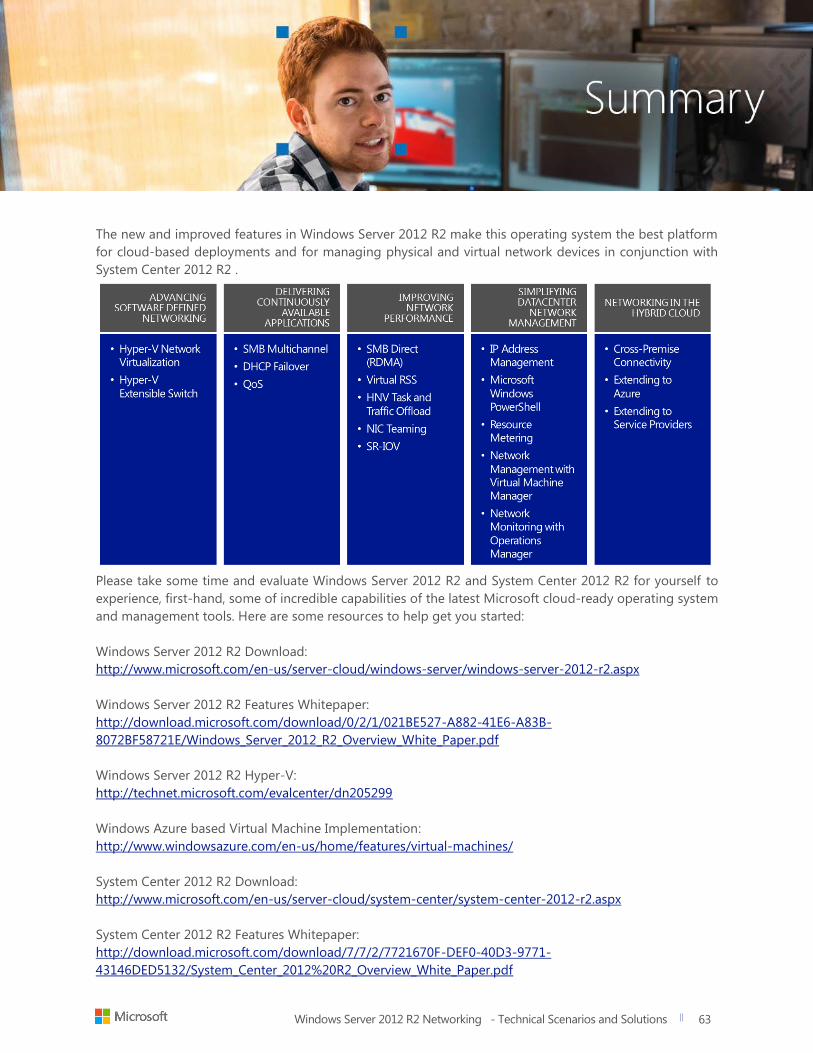
Windows Server 2012 R2 Networking - Technical Scenarios and Solutions
title of document
63
63
The new and improved features in Windows Server 2012 R2 make this operating system the best platform
for cloud-based deployments and for managing physical and virtual network devices in conjunction with
System Center 2012 R2 .
Please take some time and evaluate Windows Server 2012 R2 and System Center 2012 R2 for yourself to
experience, first-hand, some of incredible capabilities of the latest Microsoft cloud-ready operating system
and management tools. Here are some resources to help get you started:
Windows Server 2012 R2 Download:
http://www.microsoft.com/en-us/server-cloud/windows-server/windows-server-2012-r2.aspx
Windows Server 2012 R2 Features Whitepaper:
http://download.microsoft.com/download/0/2/1/021BE527-A882-41E6-A83B-
8072BF58721E/Windows_Server_2012_R2_Overview_White_Paper.pdf
Windows Server 2012 R2 Hyper-V:
http://technet.microsoft.com/evalcenter/dn205299
Windows Azure based Virtual Machine Implementation:
http://www.windowsazure.com/en-us/home/features/virtual-machines/
System Center 2012 R2 Download:
http://www.microsoft.com/en-us/server-cloud/system-center/system-center-2012-r2.aspx
System Center 2012 R2 Features Whitepaper:
http://download.microsoft.com/download/7/7/2/7721670F-DEF0-40D3-9771-
43146DED5132/System_Center_2012%20R2_Overview_White_Paper.pdf