WIND TURBINE EMULATOR WITH DC MOTOR DRIVE
6
WIND TURBINE EMULATOR WITH DC MOTOR DRIVE Zahari Zarkov, Valentin Milenov Abstract: The paper presents the development of a simulation model of a wind turbine (WT) emulator. The emulator consists of a DC motor, electronic converter and controller. The mathematical modelling of a wind turbine and separately excited DC motor with electronic converter is performed in Matlab/Simulink environment. The WT performance characteristics are described by mathematical expressions and appropriate motor torque controller is developed. Thus the motor drive is made to behave as a wind turbine. The results from simulations using the created model of the WT emulator are also shown in the paper. The developed WT emulator model is a first stage of the development of a laboratory test bench for physical simulation of a wind turbine. Keywords: DC motor, Matlab, simulation, wind turbine І. INTRODUCTION Wind energy has experienced great growth this last decade. This growth is partly due to the technological improvement of wind tur- bines, which has led to a significant decrease of wind power cost, allowing this energy source to compete with conventional generation methods. One of the important factors in the development of wind generators has been the transition from constant speed operation to variable speed. Vari- able speed operation increases the energy produc- tion and reduces the drive train torque and gener- ated power fluctuations. Experimental examina- tion of wind energy conversion systems (WECS) in a laboratory rises the problem of a mover that replaces the actual wind turbine. A wind turbine (WT) emulator would be a useful tool to add to a test bench for studying of electric generators and power electronic converters used in WECS in la- boratory conditions. The emulator should drive the wind turbine generator in a similar way as a wind turbine reproducing the torque developed for a given wind velocity and rotational speed. The fundamental aspects for modelling the behaviour of wind turbines are widely dis- cussed in literature. The mechanical power and torque output of the turbine is represented as a function of wind speed, air density, turbine rota- tional speed and swept area. These relationships are the basis for the building of a WT emulator [1]. The most convenient way for emulating the behaviour of a wind turbine in a laboratory is the use of an electric motor drive directly coupled to the shaft of the generator. The drive can be based on a DC motor as it is shown in [2]-[6] or on AC induction motor [7]-[9]. Generally the DC motor is the better choice for a WT emulator as it can be controlled by the armature current that is directly related to the torque produced by the machine. Besides, the DC motor is simply to control and its dynamic characteristics are very good [2]. Com- puter simulation models of WT emulators with DC motors are proposed in [1], [3]. Other authors have developed experimental setups [2], [5], [6]. Another alternative for an accurate torque control is induction motor drive using field oriented con- trol or direct torque control [7], [8], [9]. The main goal of this research is to de- velop a simulation model of a wind turbine emu- lator based on a DC motor drive in the Matlab/Simulink environment. The model should be appropriate for further creation of a test bench for emulation of a WT in laboratory conditions. ІІ. GENERAL DESCRIPTION OF THE WIND TURBINE EMULATOR The wind turbine emulator will be built using a 1.5kW separately excited DC motor sup- plied by an H-bridge transistor electronic con- verter with PWM. The block diagram of the pro- posed wind turbine emulator is shown in Figure 1. Figure 1. Simplified block diagram of the wind turbine emulator. The main idea is to replace the wind tur- bine rotor and gearbox with a PC, controller, Grid DCM DC motor converter Power electronic converter Controller PC SG Wind data SG AC power supply ELMA 2015 October, Varna, Bulgaria 146
Transcript of WIND TURBINE EMULATOR WITH DC MOTOR DRIVE

WIND TURBINE EMULATOR WITH DC MOTOR DRIVE
Zahari Zarkov, Valentin Milenov
Abstract: The paper presents the development of a simulation model of a wind turbine (WT) emulator. The emulator consists of a DC motor, electronic converter and controller. The mathematical modelling of a wind turbine and separately excited DC motor with electronic converter is performed in Matlab/Simulink environment. The WT performance characteristics are described by mathematical expressions and appropriate motor torque controller is developed. Thus the motor drive is made to behave as a wind turbine. The results from simulations using the created model of the WT emulator are also shown in the paper. The developed WT emulator model is a first stage of the development of a laboratory test bench for physical simulation of a wind turbine. Keywords: DC motor, Matlab, simulation, wind turbine
І. INTRODUCTION
Wind energy has experienced great growth this last decade. This growth is partly due to the technological improvement of wind tur-bines, which has led to a significant decrease of wind power cost, allowing this energy source to compete with conventional generation methods. One of the important factors in the development of wind generators has been the transition from constant speed operation to variable speed. Vari-able speed operation increases the energy produc-tion and reduces the drive train torque and gener-ated power fluctuations. Experimental examina-tion of wind energy conversion systems (WECS) in a laboratory rises the problem of a mover that replaces the actual wind turbine. A wind turbine (WT) emulator would be a useful tool to add to a test bench for studying of electric generators and power electronic converters used in WECS in la-boratory conditions. The emulator should drive the wind turbine generator in a similar way as a wind turbine reproducing the torque developed for a given wind velocity and rotational speed.
The fundamental aspects for modelling the behaviour of wind turbines are widely dis-cussed in literature. The mechanical power and torque output of the turbine is represented as a function of wind speed, air density, turbine rota-tional speed and swept area. These relationships are the basis for the building of a WT emulator [1]. The most convenient way for emulating the behaviour of a wind turbine in a laboratory is the use of an electric motor drive directly coupled to the shaft of the generator. The drive can be based on a DC motor as it is shown in [2]-[6] or on AC induction motor [7]-[9]. Generally the DC motor is the better choice for a WT emulator as it can be controlled by the armature current that is directly
related to the torque produced by the machine. Besides, the DC motor is simply to control and its dynamic characteristics are very good [2]. Com-puter simulation models of WT emulators with DC motors are proposed in [1], [3]. Other authors have developed experimental setups [2], [5], [6]. Another alternative for an accurate torque control is induction motor drive using field oriented con-trol or direct torque control [7], [8], [9].
The main goal of this research is to de-velop a simulation model of a wind turbine emu-lator based on a DC motor drive in the Matlab/Simulink environment. The model should be appropriate for further creation of a test bench for emulation of a WT in laboratory conditions.
ІІ. GENERAL DESCRIPTION OF THE WIND TURBINE EMULATOR
The wind turbine emulator will be built using a 1.5kW separately excited DC motor sup-plied by an H-bridge transistor electronic con-verter with PWM. The block diagram of the pro-posed wind turbine emulator is shown in Figure 1.
Figure 1. Simplified block diagram of the wind
turbine emulator. The main idea is to replace the wind tur-
bine rotor and gearbox with a PC, controller,
Grid
DCM
DC motor converter
Power electronic converter
Controller
PC
SG
Wind data
SG
AC power supply
ELMA 2015 October, Varna, Bulgaria
146
power electronic converter and DC motor. The DC motor is directly coupled to the
generator shaft. In the particular case is used a synchronous generator that is connected to the electrical grid via second electronic converter. This converter is a combination of a diode recti-fier and single-phase transistor inverter. III. MATHEMATICAL MODELLING
1. Wind turbine model The performance characteristics of the
wind turbine have specific shape, which depends on the turbine geometry, wind speed, pitch angle etc. [2], [4], [5], [8], [9].
The turbine’s mechanical output power P is expressed as
(1) = 12
where: ρ is the air density, V is the wind speed, A is the area swept by the rotor blades and CP is the WT power coefficient.
The swept area is
(2) =
where: Rt is the turbine radius. The aerodynamic torque of the wind
turbine Tt is calculated as
(3) =
where: ωt is the angular velocity of the turbine. After substitution of (2) in (3) the torque
expression becomes
(4) = 12 . . CT is aerodynamic torque coefficient that
relates to CP by the tip speed ratio (TSR) λ
(5) = . Based on (4), (5) and (2) the torque is
calculated as
(6) = 12 . The TSR is the ratio of the linear speed
of the blade tip and the wind speed. It is given as
(7) = . The power coefficient CP describes the
energy conversion efficiency of a wind turbine. It is a nonlinear function of TSR λ and blade pitch
angle β characterizing the aerodynamic behav-iour of the turbine
(8) = , . The CP value is different for each turbine
type. Usually it is given by turbine manufactures as curve or in a look-up table.
For theoretical models of CP (λ, β) have been developed various analytical functions. One of the most appropriate functions is the following [2], [5], [8], [ 9]:
(9) = . 1− . − . + .
where:
(10) = 1
+ − + 1.
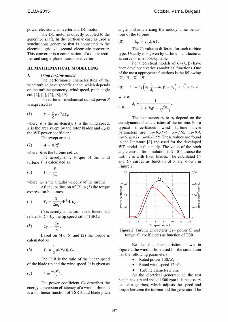
The parameters a1 to a6 depend on the aerodynamic characteristics of the turbine. For a typical three-bladed wind turbine these parameters are: a1=0.5176, a2=116, a3=0.4, a4=5, a5=21, a6=0.0068. These values are found in the literature [8] and used for the developed WT model in this study. The value of the pitch angle chosen for simulation is β= 0º because the turbine is with fixed blades. The calculated CP and CT curves as function of λ are shown in Figure 2.
Figure 2. Turbine characteristics – power CP and
torque CT coefficients as function of TSR. Besides the characteristics shown in
Figure 2 the wind turbine used for the simulation has the following parameters:
• Rated power 1.8kW; • Rated wind speed 12m/s; • Turbine diameter 2.6m. As the electrical generator in the test
bench has a rated speed 1500 rpm it is necessary to use a gearbox, which adjusts the speed and torque between the turbine and the generator. The
0
0,02
0,04
0,06
0,08
0
0,1
0,2
0,3
0,4
0 2 4 6 8 10 12 14
Torq
ue c
oeffi
cien
t CT
Pow
er c
oeffi
cien
t CP
Tip speed ratio λ
CP
CT
ELMA 2015 October, Varna, Bulgaria
147

gear ratio is 1:2.4 and it is assumed that the efficiency of gearbox is 1 (no losses).
The block diagram of the wind turbine simulation model built according to equations (1) to (10) is shown in Figure 3.
Figure 3. Wind turbine simulation model.
2. DC motor model The motor used for the WT emulator is a
separately excited DC motor. The mathematical model of the DC motor is given as follows. For the armature circuit
(11) = . + +
where: Va is the armature voltage, ia – armature current, Ra – armature resistance, ω – rotor angu-lar speed; La – armature inductance; ke – electro-motive force constant and Φ – the main flux.
For the field circuit the equation is
(12) = . +
where: Vf is the field voltage, if – the field cur-rent, Ra – field winding resistance; Lf – field winding inductance.
The electromagnetic toque of the motor is
(13) = .
In the WT emulator the shaft of the DC motor is directly coupled to the shaft of the elec-tric generator without any gearbox. Consequently the rotational speed of the generator is equal to this of the motor.
Mechanical part of the system is described by the equation of the motion
(14) . + = −
where: J is the total inertia adduced to the motor shaft, Tg is the generator torque, Tloss – the torque due to the losses in the DC motor.
The torque on the DC motor shaft is
(15) = − . The motor losses are obtained from
experimental testing and calculations. The loss
torque is represented as a straight line in function of the motor speed at constant excitation current as follows
(16) = +
where: B is the viscous friction coefficient and T0 is the friction torque.
As the wind turbine and the gear box are replaced by the DC motor the relations between the turbine speed ωt and torque Tt and those of the motor are as follows:
(17) =
(18) =
where: ng is the gear ratio.
3. Controller model The main purpose of the controller is to
calculate and adjust the torque and the speed of the motor so as it reproduces exactly the torque-speed characteristics of the modelled wind turbine at given wind speed.
This goal is achieved by applying torque control of the DC motor on the basis of the refer-ence wind velocity V and feedback signals for ro-tor speed n and armature current ia. The torque control is performed by regulating the motor ar-mature current via an inner current control loop.
The block diagram of the developed sim-ulation model of the wind turbine emulator is shown in Figure 4. The wind velocity and rotor speed are fed to the turbine model where the mo-tor reference torque T* is calculated by equations (1) to (10) and (17) implemented in the model on Figure 3. As the turbine is small and it is with fixed blades (stall-controlled) the value of the pitch angle is assumed to be β= 0º.
Reference torque is then used for calcu-lation of the motor reference current ∗according to equations (13), (15), (16)
(19) ∗ = ∗+
. The current reference is an input for the
current controller with PI structure. The output of the current controller is connected to the ana-logue input of the electronic converter which supplies the armature of the DC motor. This converter has a full-bridge structure with MOSFETs and operates with PWM frequency of 12.5 kHz. At this frequency the DC motor operates entirely in continuous current mode
TSR(λ)
ωt λ λiλiCp
WT
pow
er c
alcu
latio
n PT*V
ωt
Power limiter
Torque calc.
β
V
ω
Gearng
ELMA 2015 October, Varna, Bulgaria
148
(CCM) and has linear characteristics. That’s why in the Simulink an averaged model is adopted and the electronic converter is represented as a con-trolled DC voltage source (see Figure 4). The mechanical load of the WT emulator is the synchronous generator. In the model it is represented as a load torque applied to the motor. III. SIMULATION RESULTS
Various simulations are performed with the developed model in order to validate its per-formance. The parameters used in the simulation models are listed in Table 1.
Table 1. DC motor parameters
Rated voltage 220V
Armature resistance, Ra 3.7Ω
Field resistance, Rf 354Ω
Armature inductance, La 53mH
Field inductance, Lf 30H
Electromotive force constant, keΦ 1.1Vs
Viscous friction coefficient, B 0.0023Nms
Friction torque, T0 0.418Nm
The total inertia adduced to the motor
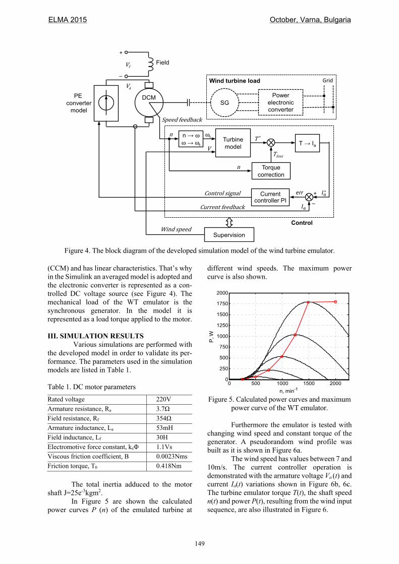
shaft J=25e-3kgm2. In Figure 5 are shown the calculated
power curves P (n) of the emulated turbine at
different wind speeds. The maximum power curve is also shown.
Figure 5. Calculated power curves and maximum
power curve of the WT emulator. Furthermore the emulator is tested with
changing wind speed and constant torque of the generator. А pseudorandom wind profile was built as it is shown in Figure 6a.
The wind speed has values between 7 and 10m/s. The current controller operation is demonstrated with the armature voltage Va (t) and current Ia(t) variations shown in Figure 6b, 6c. The turbine emulator torque T(t), the shaft speed n(t) and power P(t), resulting from the wind input sequence, are also illustrated in Figure 6.
0 500 1000 1500 20000
250
500
750
1000
1250
1500
1750
2000
n, min-1
P, W
Figure 4. The block diagram of the developed simulation model of the wind turbine emulator.
DCM
Grid
n V
+
_
FieldVfPower
electronic converter
Supervision
Current controller PI
Turbine model
PE converter
model
T*Torque
correction
Tloss T → Ia
nn → ωω → ωt
ωt
_+errControlsignalCurrentfeedback
Windspeed
SpeedfeedbackVa
Control
Wind turbine load
SG
ELMA 2015 October, Varna, Bulgaria
149

Figure 6. Turbine emulator operation at changing wind speed and constant load torque 4Nm.
Figure 7 displays the evolution of the op-
eration point of the system in the plane (n, T). The equilibrium operating points are the intersection points between the load torque line (characteristic of the generator) and the turbine characteristics. As can be observed, when а wind speed change occurs, the speed n evolves with the dominant mechanical time constant of the system, until а new equilibrium point is reached. So also does Т, which progresses over the curve of the corresponding wind speed.
Figure 7. Trajectory of the working point in the (n, T) plane during the operation of the WTE.
Figure 8 shows the results from the
simulation of the WT emulator at constant wind
speed V=10m/s and changing load torque. The increase of the load torque leads to decrease in the turbine speed and increase in the produced power. This is because the operating point in this case is moving on the right side of the T(n) char-acteristic of the turbine.
Figure 8. Turbine emulator operation at constant wind speed 10m/s and changing load torque.
In the real test bench there will be differ-
ences between the actual motor parameters and those used in the control program. Besides, the speed and the current will be measured with cer-tain errors. All this will lead to not perfect repro-duction of the reference turbine operating point that is issued by the turbine model.
In order to simulate this behaviour of the real system a Simulink model comprising a WT reference model and WTE model is created ac-cording to Figure 9.
Figure 9. Simulink model for comparison of WT reference model and WTE model operation.
0 2 4 6 8 100
5
10V
, m/s
0 2 4 6 8 100
100200300
Va,
V
0 2 4 6 8 100
5
10
Ia, A
0 2 4 6 8 100
5
10
T, N
m
0 2 4 6 8 100
1000
2000
n, m
in-1
0 2 4 6 8 100
500
1000
Time, s
P,W
a)
b)
d)
e)
f)
c)
0 2 4 6 8 100
5
10
Tl,N
m
0 2 4 6 8 100
150
300
Va,
V
0 2 4 6 8 100
4
8
Ia, A
0 2 4 6 8 100
5
10
T, N
m
0 2 4 6 8 100
1000
2000
n, m
in-1
0 2 4 6 8 100
5001000
Time, s
P,W
a)
b)
c)
d)
e)
f)
WT reference model
WT emulator model
Speed
Wind speed
V
n
V
P
Load torque Tl
WT speed n
WT speed ne
V
n
ELMA 2015 October, Varna, Bulgaria
150

Some typical errors are introduced in the WT emulator model:
• Speed measurement error +1%; • Current measurement error -4%. The results from the simulation are
shown in Figure 10 where T(n) characteristics of the WT emulator are compared with those of the reference WT model.
Figure 10. T(n) characteristics of the WT model (solid lines) and WT emulator model (x marks).
As it can be seen the WTE operating
points tend to deviate from the WT characteris-tics due to inaccurate measurements of the feed-back quantities. IV. CONCLUSIONS
A model of a wind turbine emulator has been designed to thoroughly reproduce the be-haviour of a wind turbine using the wind profile as input. The WT emulator is based on DC motor drive with direct coupling with the electrical gen-erator without gear box. The model is developed in Matlab/Simulink environment and gives the possibility to simulate the turbine operation under different conditions – variable wind speed, load torque and rotational speed.
The results of the simulation demonstrate that the chosen approach is good and the system has the capabilities to behave like a wind turbine subjected to exigent and repetitive wind condi-tions.
Further work will include a building of a real set-up of the proposed emulator, based on a DC motor and a microcontroller with appropriate software. By implementing the emulator on a test bench, it will be possible to validate and analyse different control strategies for wind energy con-version systems.
ACKNOWLEDGMENT The authors would like to thank the
Technical University of Sofia, Bulgaria for providing financial support of this research under Contract 151ПД0038-01, Development support of PhD students. LITERATURE: [1]. Jansuya P., Kumsuwan Y., Design of MATLAB/Simulink Modeling of Fixed-pitch Angle Wind Turbine Simulator. Energy Procedia, Vol. 34, 2013, pp. 362-370. [2]. Ovando R.I., Aguayo J., Cotorogea M., Emulation of a Low Power Wind Turbine with a DC motor in Matlab/Simulink. Power Electronics Specialists Conference PESC 2007, June 2007, pp. 859-864. [3]. Monfared M., Kojabadi H.M., Rastegar H., Static and Dynamic Wind Turbine Simulator Using a Converter Controlled DC Motor. Renewable Energy, Vol. 33, No. 5, May 2008, pp. 906-913. [4]. Chaurasia K., Chaurasia K., Emulation of a 1 MW Wind Turbine System with a Separately Excited: DC Motor Using MATLAB-SIMULINK. International Journal of Innovative Research & Development, Vol. 3, Issue 10, October 2014, pp. 103-109. [5]. Himani G., Dahiya R., Design and Development of Wind Turbine Emulator to Operate with 1.5kW In-duction Generator. Advanced Energy: An Interna-tional Journal, Vol. 1, No. 4, October 2014, pp. 1-10. [6]. Weiwei Li, Dianguo Xu, Wei Zhang, Hongfei Ma, Research on Wind Turbine Emulation based on DC Motor. 2nd IEEE Conf. on Industrial Electronics and Applications, ICIEA 2007, 23-25 May 2007, pp. 2589-2593. [7]. Mohod S.W., Aware M.V., Laboratory develop-ment of wind turbine simulator using variable speed induction motor. Int. Journal of Engineering, Science and Technology, Vol. 3, No. 5, 2011, pp. 73-82. [8]. Voltolini H., Granza M.H., Ivanqui J., Carlson R., Modeling and simulation of the Wind Turbine Emula-tor using induction motor driven by torque control in-verter. 10th IEEE/IAS Int. Conf. on Industry Applica-tions (INDUSCON), 5-7 Nov. 2012, pp.1-6. [9]. Sokolovs A., Grigans L., Kamolins E., et al. An Induction Motor Based Wind Turbine Emulator. Lat-vian Journal of Physics and Technical Sciences, 51(2), 2014, pp. 11-21. Contacts: Zahari Zarkov, Faculty of Electrical Engineering, Technical University of Sofia, 8 Kl. Ohridski blvd., 1000 Sofia, Bulgaria. Phone: +359-2-965-2461, e-mail: [email protected] Valentin Milenov, Faculty of Electrical Engineering, Technical University of Sofia, 8 Kl. Ohridski blvd., 1000 Sofia, Bulgaria. Phone: +359-2-965-2465, e-mail: [email protected]
0 500 1000 1500 20000
2
4
6
8
10
12
14
n, min-1
Torq
ue, N
m
10m/s
12m/s
4m/s
6m/s
8m/s
ELMA 2015 October, Varna, Bulgaria
151