Wind Turbine Drivetrain Testing and Research at the ... · Main shaft, gearbox, coupling, and...
26
NREL/PR-5000-62887 NREL is a national laboratory of the U.S. Department of Energy, Office of Energy Efficiency and Renewable Energy, operated by the Alliance for Sustainable Energy, LLC. Wind Turbine Drivetrain Testing and Research at the National Renewable Energy Laboratory Jonathan Keller [email protected] Pennsylvania State University University Park, Pennsylvania September 15, 2014
-
Upload
nguyencong -
Category
Documents
-
view
217 -
download
0
Transcript of Wind Turbine Drivetrain Testing and Research at the ... · Main shaft, gearbox, coupling, and...
NREL/PR-5000-62887 NREL is a national laboratory of the U.S. Department of Energy, Office of Energy Efficiency and Renewable Energy, operated by the Alliance for Sustainable Energy, LLC.
Wind Turbine Drivetrain Testing and Research at the
National Renewable Energy Laboratory
Jonathan Keller [email protected]
Pennsylvania State University University Park, Pennsylvania September 15, 2014

2
Wind Power Industry Overview
• Wind energy today… o Multibillion dollar industry with multinational corporations o 60+ gigawatts (GW) deployed (~5% of U.S. electricity) o Land-based wind @ 7-8 ₵/kilowatt-hour (kWh); beating coal o Leads all renewable technology deployment.
• Tremendous opportunity remains… o Achieve parity with
natural gas at 5–6 ₵/kWh
o Establish offshore wind o Provide research and
development (R&D) to achieve 30% wind.
Source: AWEA
National Wind Technology Center Overview

4
U.S. Department of Energy National Wind Technology Center
• Turbine testing since 1977 • Leader in development of design and analysis codes • Pioneers in component testing • Modern utility-scale turbines
• 130–160 personnel on-site • Partnerships with industry, CRADAs, and work-for-others • Leadership roles for international standards • Offshore wind and marine and hydrokinetic technology development.
• Unique test facilities: - Megawatt-scale turbines and sites - Blade testing - Dynamometers - Controls research turbines
Photo by Dennis Schroeder, NREL 30764

5
Current Test Facilities • Field
o Field test sites and infrastructure o DOE 1.5, industry megawatt (MW) turbines,
small turbines o Controls Advanced Research Turbines (CARTs) o Research-grade inflow meteorological data.
• Drivetrain o 225-kW, 2.5-MW, and 5-MW dynamometers o Dynamic torque testing of fully integrated
drivetrain systems (gearboxes, generators, PE) o Model-in-the-loop (to simulate turbulence). o Non-torque loading to simulate rotor loads
• Blade o Static testing and resonant fatigue testing to 50
meters (m) o Accredited (A2LA) fatigue (resonant) and static
testing of blades to IEC standards, modal and blade property measurements, profiling
o Innovative blade test methodology R&D o Massachusetts large blade test facility.
• ISO 17025, A2LA-accredited to IEC Standards o Power performance, power quality, acoustic
emissions, structural loads, duration, and structural and fatigue testing.
Photo by Lee Jay Fingersh, NREL 14688
Photo by Dennis Schroeder, NREL 30780 Photo by Lee Jay Fingersh,
NREL 16269

6
Multimegawatt Turbines • GE 1.5 MW
o Model: GE 1.5 SLE o Tower height: 80 m; rotor diameter: 77 m o DOE-owned; used for research and education o Turbine commissioned September 2009.
• Siemens 2.3 MW o Model: SWT-2.3-101 o Tower height: 80 m; rotor diameter: 101 m.
• Alstom 3 MW o Model: ECO 110 o Tower height: 90 m; rotor diameter: 110 m.
• Gamesa 2 MW o Model G97 o Tower height: 90 m; rotor diameter: 97 m.
Photo by Dennis Schroeder, NREL 30770

7
New 5-MW Dynamometer • 5.8 MW (low-speed shaft) • 12–4 rpm (at full power) • 4.6 MNm (3.4 M ft-lb) max
torque • Non-torque loads in 5 DOF • Dual 75-ton cranes • 20 m x 12 m test bay • 5 degree drive table tilt
2.5-MW Dynamometer • 2.5 MW (low-speed shaft) • 17–31 rpm (at full power) • 1.64 MNm (1.2 M ft-lb) max
torque • Non-torque loads in 3
degrees of freedom (DOF) • Single 50-ton crane • 12.2 m x 15.2 m test bay • 0–6 degree drive table tilt
Dynamometer Facilities
Designed to test entire integrated wind turbine drivetrain system
Photo by Lee Jay Fingersh, NREL 16267
Photo by Robb Wallen, NREL 17400
Photo by Mark McDade, NREL 27249
8
Non-torque loading system
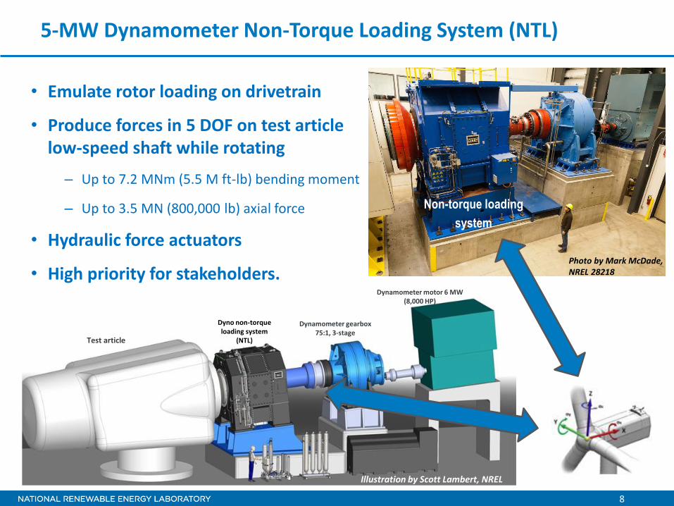
• Emulate rotor loading on drivetrain
• Produce forces in 5 DOF on test article low-speed shaft while rotating
– Up to 7.2 MNm (5.5 M ft-lb) bending moment
– Up to 3.5 MN (800,000 lb) axial force
• Hydraulic force actuators
• High priority for stakeholders.
5-MW Dynamometer Non-Torque Loading System (NTL)
Dynamometer motor 6 MW (8,000 HP)
Dyno non-torque loading system
(NTL)
Dynamometer gearbox 75:1, 3-stage
Test article
Photo by Mark McDade, NREL 28218
Illustration by Scott Lambert, NREL

9
NWTC Controllable Grid Interface (CGI) Facility
o CGI connected to both dynos and some turbines
o Command voltage profiles to emulate real power-line faults
o 7 megavolts-ampere (MVA) continuous with 28 MVA short circuit capacity
Dyno motor 6 MW (8,000 HP)
Dyno non-torque loading
system
Dyno variable frequency
drive Test article power
converter Dyno gearbox 75:1, 3-stage Test article
drivetrain
Test article transformer
Photo by Dennis Schroeder, NREL 25890
Illustration by Scott Lambert, NREL

Gearbox Reliability Collaborative
http://www.nrel.gov/wind/grc/index.html
Sponsor: DOE EERE Wind
11
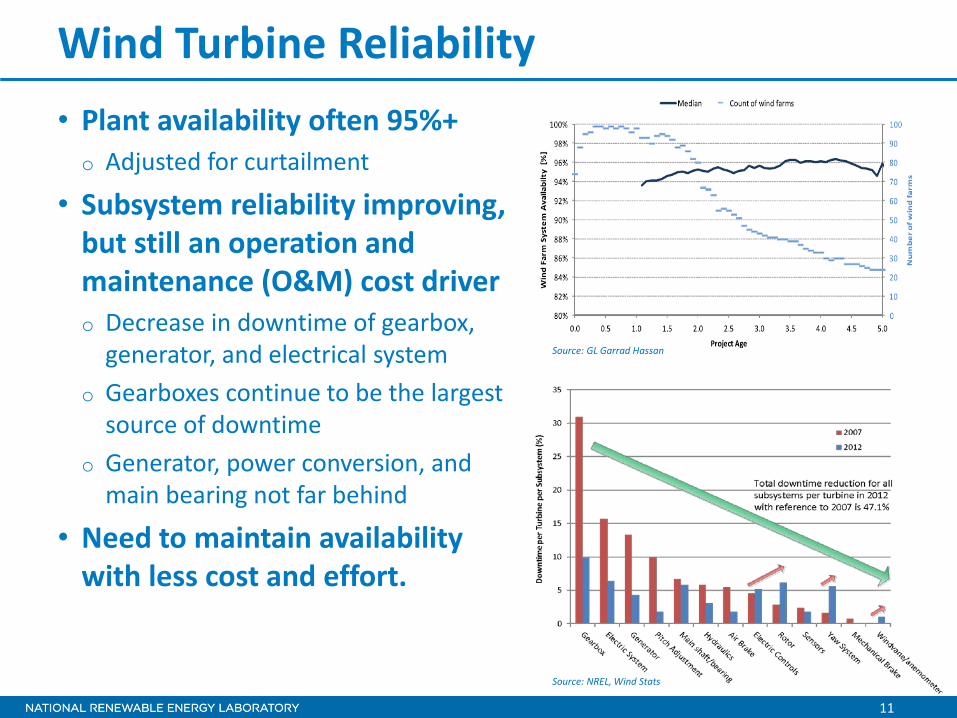
Wind Turbine Reliability • Plant availability often 95%+ o Adjusted for curtailment
• Subsystem reliability improving, but still an operation and maintenance (O&M) cost driver o Decrease in downtime of gearbox,
generator, and electrical system o Gearboxes continue to be the largest
source of downtime o Generator, power conversion, and
main bearing not far behind
• Need to maintain availability with less cost and effort.
Source: NREL, Wind Stats
Source: GL Garrad Hassan

12
Typical Wind Turbine Drivetrain Architecture
• Modular, three-point mounting system o Main bearing and gearbox torque arms
• Three-stage gearbox o Ratio of 80 or 100:1 o Three-planet stage(s) o Floating sun o Parallel stage(s).
Generator
Main Bearing Main Shaft
Brake Generator Shaft
Gearbox
Bed Plate
Hub
Torque Arms

13
NREL Gearbox Failure Database
• Gearbox failure event data highlighting damaged components, failure modes, and possible root causes o Twenty partners involved in operating ~30% of the U.S. capacity o Number of gearbox failure incidents = 289.
• Observations o Bearings 70% o Gears 26% o Parallel section faults
most common o High-speed and
intermediate-speed stage (HSS and IMS) bearing axial cracking most common failure mode.
HSS Bearing Helical Gear
IMS Bearing
Planet Bearing
Planet Gear

14
Photo by Jeroen van Dam, NREL 19257
Gearbox Reliability Collaborative
Test Validate Analyze Redesign Propagate
• Potential causes: o Underspecified loads? o Inaccurate design tools? o Inadequate design practice? o Insufficient testing?
• Solution process: o Conduct field and dynamometer
testing to measure responses (150+ signals)
o Validate modeling approaches (multibody, finite element analysis)
o Analyze design deficiencies (cylindrical roller bearing [CRB] clearance)
o Redesign gearbox to correct (preloaded tapered roller bearings [TRBs])
o Propagate lessons learned to industry and standards.
Field test
Dynamometer test
Analysis • Load cases • System loads • Internal loads
NREL dynamometer. Photo by Lee Jay Fingersh, NREL 16913

15
GRC Implementation • Use smaller 750-kW drivetrain to control costs • Lack of public models → re-design/re-build commercial gearbox (GB) o First iteration (GB 1&2) brings to state of the art circa 2007 o Second iteration (GB 3) brings to state of the art circa 2012.
• Significant internal and external instrumentation o Main shaft, gearbox, coupling, and generator displacements o Planetary section loads, motions, and temperatures o HSS, pinion, and bearing loads recently added.
NREL dynamometer. Photo by Lee Jay Fingersh, NREL 16913

16
New HSS Instrumentation
Slip rings Pinion tooth toot strain for Gear Khβ
Bearing strain for relative loading (four axial slots, two Poisson gauges per slot,)
and temperature (both bearings)
Shaft bending strain (two axes, three axial locations,)
and shaft torsion for torque
Encoder for azimuth and speed
Photo by Scott Naucler, NREL 26259
Photo by Jon Keller, NREL 27895
Photo by Scott Naucler, NREL 30252
Photo by Scott Naucler, NREL 30250
Photo by Scott Naucler, NREL 30251

17
Test Summary
• Phase 1 (300+ hours of data) o GB 1 field load test
– Oil loss event led to GB damage
• Phase 2 (700+ hours of data) o GB 2 dynamometer static load test o GB 1 dynamometer test
– Condition monitoring and GB teardown
• Phase 3 (underway) o GB 2 dyno re-test
– HSS loads, dynamic field loads, and generator misalignment
o Improved GB 3 test.
Apr
2009
Oct 2009
July 2010
Nov 2010
Jan
2011
Jan 2013
Jan
2015
Ponnequin Wind Farm. Photo by Jeroen van Dam, NREL 19257

18
Gearbox 1 & 2 Design Deficiencies • Non-Torque and Planetary Loads
o Significant effect in three-point configuration
o Cause edge loading on planetary gear teeth
– Misalignment between carrier and ring gear because of operating radial clearance in carrier bearings
o Cause poor load share between planets and upwind and downwind planetary bearings
– Carrier wind-up and planetary pin deflection with operating radial clearance in the CRBs
– High bearing skidding risks at low torque.
Photo by Ed Overly, NREL 19494

19
Carrier Bearings
Planet Bearings
Ring/Torque Arm/Housing
Joint
Ring Gear
Hollow Shaft Bearings Improved
Reliability
Lubrication
Gearbox 3 Design Improvements Illustration by Romax Technology
Project Team: Romax Technology Powertrain Engineers Timken Brad Foote Gearing

20
TRBs used to improve planetary
alignments with load variation
Robust bolt system to accommodate
increased housing load from TRBs
Nitrided to improve fatigue life
Integral TRBs; improve load share
and eliminate outer race fretting
X-arrangement; tighter inner rings
to avoid slip
Carrier radial feed; three feeds center
plate; spray all gears;
high-speed TRBs axial feed
Gearbox 3 Design Improvements Illustration by Romax Technology

NREL is a national laboratory of the U.S. Department of Energy, Office of Energy Efficiency and Renewable Energy, operated by the Alliance for Sustainable Energy, LLC.
Next Generation Drivetrain
Sponsor: DOE EERE Wind
Project Team: NREL CREE DNV KEMA Romax Technology Vattenfall Windpower
http://apps1.eere.energy.gov/wind/newsletter/detail.cfm/articleId=189
22
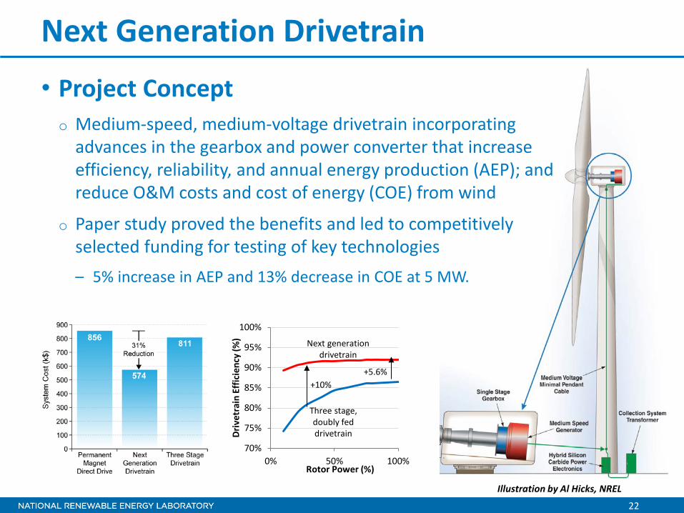
Next Generation Drivetrain
• Project Concept o Medium-speed, medium-voltage drivetrain incorporating
advances in the gearbox and power converter that increase efficiency, reliability, and annual energy production (AEP); and reduce O&M costs and cost of energy (COE) from wind
o Paper study proved the benefits and led to competitively selected funding for testing of key technologies – 5% increase in AEP and 13% decrease in COE at 5 MW.
70%
75%
80%
85%
90%
95%
100%
0% 50% 100%
Driv
etra
in E
ffic
ienc
y (%
)
Rotor Power (%)
Next generation drivetrain
Three stage, doubly fed drivetrain
+10% +5.6%
Illustration by Al Hicks, NREL

23
Technology Development and Testing
• Gearbox journal bearing and flex pin robustness o Ferrium C61 explored on paper
• Converter grid fault control software effectiveness
• Reuse WindPACT generator
• Medium voltage, hybrid Si/SiC module performance
Dynamometer Power Converter Modules
650-kW drivetrain technology test bed
Medium voltage Hybrid Si/SiC
Module test bed
Photo by CREE
Photo by DNV KEMA

24
Current Activities and Results
• Gearbox in manufacture at Brad Foote Gearing • Converter software in development at DNV o NERC/FERC grid interconnectivity requirements emerging
• Hybrid Si/SiC modules in manufacture at Powerex o High-efficiency, medium-voltage power conversion a focus in
many industries
• Drivetrain and module testing complete early 2015.

Wrap-Up

26
Opportunities for Researchers and Students
• Researchers o Research Participant Program (RPP)
– http://www.nrel.gov/rpp/ – https://www.youtube.com/watch?v=0TBeFWGU0T8
• Students and Educators o Science Undergraduate Laboratory Internships (SULI)
– http://www.nrel.gov/education/suli_intern.html – https://www.youtube.com/watch?v=tAppljjGXLM
o Graduate Fellowship Program – http://www.nrel.gov/education/scgsr.html
o Visiting Faculty Program – http://www.nrel.gov/education/teachers.html#fast
• Full-time Employment o http://www.nrel.gov/employment/