Wind Power Applications of Doubly-Fed...
31
Citation: Jovanovic, Milutin and Chaal, Hamza (2017) Wind power applications of doubly-fed reluctance generators with parameter-free hysteresis control. Energy Conversion and Management, 134. pp. 399-409. ISSN 0196-8904 Published by: Elsevier URL: http://dx.doi.org/10.1016/j.enconman.2016.10.064 <http://dx.doi.org/10.1016/j.enconman.2016.10.064> This version was downloaded from Northumbria Research Link: http://nrl.northumbria.ac.uk/28890/ Northumbria University has developed Northumbria Research Link (NRL) to enable users to access the University’s research output. Copyright © and moral rights for items on NRL are retained by the individual author(s) and/or other copyright owners. Single copies of full items can be reproduced, displayed or performed, and given to third parties in any format or medium for personal research or study, educational, or not-for-profit purposes without prior permission or charge, provided the authors, title and full bibliographic details are given, as well as a hyperlink and/or URL to the original metadata page. The content must not be changed in any way. Full items must not be sold commercially in any format or medium without formal permission of the copyright holder. The full policy is available online: http://nrl.northumbria.ac.uk/policies.html This document may differ from the final, published version of the research and has been made available online in accordance with publisher policies. To read and/or cite from the published version of the research, please visit the publisher’s website (a subscription may be required.)
Transcript of Wind Power Applications of Doubly-Fed...

Citation: Jovanovic, Milutin and Chaal, Hamza (2017) Wind power applications of doubly-fed reluctance generators with parameter-free hysteresis control. Energy Conversion and Management, 134. pp. 399-409. ISSN 0196-8904
Published by: Elsevier
URL: http://dx.doi.org/10.1016/j.enconman.2016.10.064 <http://dx.doi.org/10.1016/j.enconman.2016.10.064>
This version was downloaded from Northumbria Research Link: http://nrl.northumbria.ac.uk/28890/
Northumbria University has developed Northumbria Research Link (NRL) to enable users to access the University’s research output. Copyright © and moral rights for items on NRL are retained by the individual author(s) and/or other copyright owners. Single copies of full items can be reproduced, displayed or performed, and given to third parties in any format or medium for personal research or study, educational, or not-for-profit purposes without prior permission or charge, provided the authors, title and full bibliographic details are given, as well as a hyperlink and/or URL to the original metadata page. The content must not be changed in any way. Full items must not be sold commercially in any format or medium without formal permission of the copyright holder. The full policy is available online: http://nrl.northumbria.ac.uk/policies.html
This document may differ from the final, published version of the research and has been made available online in accordance with publisher policies. To read and/or cite from the published version of the research, please visit the publisher’s website (a subscription may be required.)

Wind Power Applications of Doubly-Fed ReluctanceGenerators with Parameter-Free Hysteresis Control
Milutin Jovanovica,∗, Hamza Chaalb
aFaculty of Engineering and Environment, Department of Physics and Electrical EngineeringNorthumbria University Newcastle, Newcastle upon Tyne NE1 8ST, UK
bSiemens plc, Renewable Energy Division, Keele ST5 5NP, UK
Abstract
The development and practical implementation aspects of a novel scheme for fast
power control of the doubly-fed reluctance generator with a low-cost partially-
rated converter, a promising brushless candidate for limited speed ranges of wind
turbines, are presented in this paper. The proposed concept is derived from the
fundamental dynamic analogies between the controllable and measurable proper-
ties of the machine: electro-magnetic torque and electrical power, and flux and re-
active power. The algorithm is applied in a stationary reference frame without any
knowledge of the machine parameters, including rotor angular position or veloc-
ity. It is then structurally simpler, easier to realise in real-time and more tolerant of
the system operating uncertainties than model-based or proportional-integral con-
trol alternatives. Experimental results have demonstrated the excellent controller
response for a variety of speed, load and/or power factor states of a custom-built
generator prototype.
Keywords: Reactive power control, Sensorless power regulation, Doubly-fed
machines, Reluctance generators, Wind turbines.
∗Corresponding author
Preprint submitted to Energy Conversion and Management October 4, 2016

Nomenclature1
vp,s primary, secondary winding phase voltages [V]2
ep,s primary, secondary winding back-emf [V]3
ip,s primary, secondary winding currents [A]4
Rp,s primary, secondary winding resistances [Ω]5
Lp,s primary, secondary 3-phase self-inductances [H]6
Lm 3-phase mutual inductance [H]7
σ leakage factor (constant) = 1− L2m/(LpLs)8
λp,s primary, secondary winding flux linkages [Wb]9
λm mutual flux [Wb]10
θp,s primary, secondary flux vector angular positions [rad]11
ωp,s primary, secondary winding frequencies [rad/s]12
p, q primary, secondary winding pole-pairs13
pr number of rotor poles = p+ q14
ωrm rotor angular velocity = dθrm/dt [rad/s]15
θr rotor ‘electrical’ angular position = prθrm [rad]16
ωsyn synchronous speed = ωp/pr [rad/s]17
Pm total mechanical (shaft) power [W]18
Pp,s primary, secondary mechanical power [W]19
Te machine electro-magnetic torque [Nm]20
P,Q primary real [W] and reactive [VAr] power21
2

1. Introduction22
A brushless doubly-fed generator (BDFG) may be an attractive solution to23
reliability and maintenance issues of carbon brushes and slip-rings with a con-24
ventional doubly-excited induction generator (DFIG) while offering competitive25
performance and the same economic benefits of partial power electronics [1]. For26
a typical speed ratio of 2:1 in wind energy conversion systems (WECS), the con-27
verter derating can be about 75% of the machine itself [2]. In this sense, both28
the BDFG and DFIG are preferable to heavy and expensive multi-pole wound ro-29
tor synchronous generators (SGs) or permanent-magnet generators (PMGs) with30
fully-rated converters, which are not only costly but more prone to failures under-31
mining the otherwise high reliability of their dedicated wind turbines, gear-less32
technologies in particular [3]. Another concern for the manufacturers of large33
PMG units is the risk management of market volatility, availability and payable34
price premiums of the rare earth magnets (e.g. NdFeB) deployed [4].35
With the increasing penetration of distributed generation, the challenging re-36
quirements have been imposed by the grid integration codes for the reactive (and37
real) power support to be provided by WECS to help preserve the transient stabil-38
ity during network disturbances (e.g. voltage sags) [5]. Putting these preventive39
measures in place has revealed another important BDFG potential, the superior40
low-voltage-ride-through (LVRT) characteristics owing to the inherently higher41
impedances and thus lower fault currents relative to the equivalent DFIG [6]. This42
salient BDFG property could facilitate to a great deal the design of hardware and43
software protection for the LVRT compliant fractionally-rated converter, decreas-44
ing so the supplementary system complexity and cost of DFIG installations [7].45
DFIG turbines are known to have LVRT weaknesses and many interesting solu-46
3

tions have been recently proposed to find improvements [8]. The latest rigorous47
review of the extensive research done on this subject has been published in [9].48
However, tangible practical advances are yet to be made in this direction for the49
DFIG to become comparable to the PMG, which is amenable to fulfilling the50
LVRT obligations due to the use of a full-power converter and favorable low volt-51
age capability curves as demonstrated by the WECS field tests presented in [10].52
In order to eliminate brushes for reliable and maintenance-free operation, the53
BDFG has evolved as a self-cascaded inside-out version of the DFIG [11]. This54
means that the rotor (secondary or control) winding, usually fed from two standard55
IGBT bridges in bi-directional (‘back-to-back’) arrangement to allow both super56
and sub-synchronous speeds in either machine mode, has been moved to the stator57
and placed together with the grid-connected (primary or power) winding but of58
different pole number (Fig. 1). The necessary magnetic interaction between the59
two windings for the torque production is achieved through the rotor with half the60
total number of the stator poles [12]. Therefore, for the same number of rotor61
poles and a given line frequency, the DFIG synchronous speed would be twice62
that of the BDFG making it naturally a medium-speed machine and avoiding the63
need for a high-speed gear stage of the vulnerable 3-stage gearbox in WECS [1].64
From this point of view, the BDFG could bring higher efficiency and reliability as65
well as running costs savings in these applications, and especially off-shore [13].66
The BDFG reluctance rotor type, the Brushless Doubly-Fed Reluctance Gen-67
erator (BDFRG in Fig. 1), has several advantages over its ‘nested’ cage counter-68
part, the Brushless Doubly-Fed Induction Generator (BDFIG) [12]. Experiments69
have shown that the BDFRG can be more efficient than the BDFIG of the same70
stator frame [14]. In addition, the cage-less rotor allows the fewer parameter71
4

Figure 1: A simplified structural diagram of the BDFRG wind turbine with maximum power pointtracking and sensorless hysteresis primary power control of the generator side inverter (GSI).
dependent dynamic modeling, and intrinsically decoupled control of torque and72
primary reactive power of the BDFRG, unlike the BDFIG [15]. Similar BDFRG73
attributes are shared by the DFIG [16]. In contrast with the BDFRG or DFIG,74
the BDFIG has fairly complicated and heavily parameter sensitive model-based75
vector control [17]. Severe robustness compromises can be affiliated with direct76
torque controllers for this machine as well [18].77
Several 6/2-pole BDFRGs in a kW range have been built, one of which rated78
at 1.5 kW considered in this paper, and the other to note being a 4 kW counterpart79
reported in [19]. The more sizeable example recorded in the open literature is a80
16 kW, 8/4-pole [12]. One should also mention a 42 kW, 6/2-pole machine studied81
in [20]. The biggest prototype made so far seems to be a 6/4-pole, 100 kW [21].82
An original 2 MW, 6/2-pole design for wind turbines has also been proposed [22].83
5

Research paths on control of other machines have been largely pursued in the84
BDFRG case over the last decade or so. Although intellectually appealing, the85
non-linear sliding mode control theory developed in [23] has not been applied in86
practice to be able to judge on its viability. On the other hand, a stator frame exe-87
cuted direct torque control (DTC) algorithm has been experimentally verified us-88
ing a shaft position sensor to generate the speed feedback in [24]. This concept has89
been adapted for sensorless implementation described in [25]. In the underlying90
DTC approach, the secondary flux is estimated indirectly from the measured pri-91
mary voltages and currents at fixed line frequency by virtue of the machine double92
feeding. The back-emf integration errors (e.g. the integrator saturation) caused by93
the troublesome resistive effects at low inverter voltages and frequencies, as with94
the traditional DTC of cage induction motors, have been circumvented but at the95
expense of conspicuous estimation sensitivity to the BDFRG inductance inaccu-96
racies and unsatisfactory performance even for an unloaded machine.97
A better quality response can be attained by the weakly parameter dependent98
modification of DTC, simulated and experimentally validated in [19]. Further test99
outcomes using the same scheme have been produced in [26]. The practical stud-100
ies of the direct power control (DPC) correlative have appeared in [27]. However,101
these improved ‘direct’ control methods rely on the primary flux estimates and102
have to face inevitable phase delays and other difficulties commonly associated103
with filtering noise and transducers DC offset in measurements. Consequently,104
preliminary no-load results have been mainly shown in all these works.105
A thorough comparative analysis of vector control (VC) with primary voltage106
space vector orientation (VOC) and Field (Flux) Oriented Control (FOC) for var-107
ious loading profiles in motoring mode (BDFRM) has been done experimentally,108
6
and by simulations for the BDFRG, in [28]. The latter have been fully labora-109
tory demonstrated in [29]. The disturbance rejection abilities of the BDFRG con-110
troller(s) have been further explored in [30]. Realistic computer simulation studies111
but on a large-scale WECS level have been presented in [31]. The 2 MW BDFRG112
design parameters from [22] have been used for this VOC vs FOC performance113
comparison. Such VC algorithms offer constant and reduced switching rates en-114
tailing generally lower harmonic content, but these preferences over the DT(P)C115
may be often undermined by the tuning problems of multiple PI gains with load,116
speed and/or machine parameter variations. Besides, an encoder is required for117
current control in a rotating frame, even though purely sensorless FOC is feasible118
as documented in [32] using the maximum torque per inverter ampere objective.119
The encoder-less BDFRG operation under power factor FOC conditions, as an120
extension of this experimental VC research, has been elaborated in [33].121
The hysteresis real and reactive power control (HPQC) strategy put forward122
in this paper can overcome most of the previously addressed shortcomings of123
the concurrent torque and/or power control methodologies for the BDFRG. As124
the name implies, the underlying idea is to govern the accessible terminal quan-125
tities rather than electro-magnetic torque and/or flux, which are internal to the126
machine and susceptible to estimation errors. The obvious advantages over the127
DTC gained in this way are the algorithm simplicity and higher accuracy, the po-128
tential downside being the drive train speed oscillations that may occur in the lack129
of immediate torque regulation with large wind turbines [2]. Furthermore, unlike130
the DT(P)C methods discussed earlier, the total parameter-freedom (i.e. an exclu-131
sive reliance on measurements, and not estimates) makes the HPQC more robust,132
simpler and faster to execute. It is also easier to implement than the VC by the133
7

absence of PI tuning and intrinsic immunity to parameter uncertainties.134
2. Background theory135
The space-vector model of the primary and secondary windings in a stator136
α − β frame (Fig. 2) with standard notation and adopting motoring (BDFRM)137
convention can be represented as [34]:138
ep =dλpdt
= up −Rpip = dλpdtejθp + jωpλp
es =dλsdt
= us −Rsis = dλsdtejθs + jωsλs
λp = λpejθp = Lpip + Lmi
∗sejθr = Lpip + Lmi
∗sm
λs = λsejθs = Lsis + Lmi
∗pejθr = Lsis + Lmi
∗pm
(1)
where ipm and ism are the magnetically coupled (magnetizing) current vectors139
which come from the actual primary (ip) and secondary (is) current counterparts140
rotating at different velocities as shown in Fig. 2. This peculiar frequency mod-141
ulation through the rotor is hidden in the ejθr term in (1). Note from Fig. 2 that142
ipm = ip = ipejε and ism = is = ise
jγ in the corresponding frames [35].143
The electro-mechanical energy conversion in the machine takes places under
the following angular velocity and pole conditions with the mechanical power
relationships showing contributions of each winding [35]:
ωrm =ωp + ωsp+ q
= (1 +ωsωp
) · ωppr
= (1 +ωsωp
) · ωsyn (2)
Pm = Te · ωrm =Te · ωppr
+Te · ωspr
= Pp + Ps (3)
where ωs > 0 for super-synchronous operation (ωrm > ωsyn), ωs < 0 at sub-144
8

Figure 2: Characteristic space vectors and flux-oriented reference frames.
rm
PmPs
Pp
rm
PmPs
Pp
rm
PmPs
Pp
rm
PmPs
Pp
Motor-Subsynchronous Motor-Supersynchronous
Generator-Subsynchronous Generator-Supersynchronous
Figure 3: Reference (positive) power flow in the BDFRG for the two speed modes.
synchronous speeds1(ωrm < ωsyn), and ωs = 0 (i.e. DC secondary winding) in145
synchronous speed mode (ωrm = ωsyn) as with a classical 2pr-pole wound field146
turbo-machine. A power flow diagram conforming to (3) appears in Fig. 3.147
1The ‘negative’ frequency in this speed region simply means the opposite phase sequence ofthe secondary to the primary winding i.e. ‘clockwise’ rotation of the respective vectors in theds − qs frame as indicated in Fig. 2.
9
3. Principles and architecture of hysteresis control148
Using (3), the primary electrical power can be approximated as [24]:149
P ≈ Pp =3pr
2σLs|λm × λs|︸ ︷︷ ︸Te
· ωppr
=3ωp
2σLs
LmLp
λp︸ ︷︷ ︸λm
λs sin δ (4)
where λp, and thus λm, amplitudes are almost constant because of the primary150
winding grid connection. The real power can therefore be controlled in a station-151
ary frame through λs angle, θs, i.e. δ = θs − θm (Fig. 2) in a DTC fashion as152
slowly ωs varying θm can hardly change during a short control interval [24].153
The Q control notion has been deduced from the fact that the two windings154
jointly participate in the production of the nearly fixed air-gap flux in the BD-155
FRG. So, if one winding subsidizes more, the other should commit less in the156
flux build-up. Since the electro-magnetic phenomena are strongly linked with the157
magnetizing currents, and hence the respective flux values, one can map the pri-158
mary Q variations with those on the controllable secondary side in the sense that159
Q increase/decrease could be obtained by reducing/increasing the λs. These intu-160
itive hypotheses are easiest to prove mathematically using the Q expression that161
can be derived from the steady-state FOC form of (1) [30]:162
Q =3
2ωp
(λ2pLp− λmisd
)=
3ep2Lp
(λp − Lmisd) (5)
where ep = ωpλp ≈ up. Given that λp ≈ const, the higher Q from the grid, the163
lower isd, and thus is, and vice-versa. Since σLsis has qualitatively the same trend164
as is does, so will λs in keeping with the phasor diagram in Fig. 2.165
10
3.1. Inverter voltages and power implications166
The usual binary representations of the inverter legs switching status for the167
six active voltage vectors (uk), where k denotes the attributed sector number (e.g.168
u1 ≡ 100, u2 ≡ 110 etc.), are illustrated in Fig. 4. It has been shown in [24] that169
the other two zero-vectors (e.g. ‘111’ and ‘000’) have contradictory influences170
on Te and λs behavior above and below the synchronous speed (ωsyn). The same171
holds true for their dual quantities, P and Q, which are control variables here.172
So, precise speed sensing or estimation is imperative in this case, and especially173
near or at ωsyn where the BDFRG is normally operated anyway. Needless to174
say that this would complicate the HPQC design and implementation. Another175
serious challenge in this speed region, which is equivalent to a low frequency176
operation of cage induction machines, are the detrimental Rs effects leading to177
unwanted λs weakening and control degradation if the zero vectors are repeatedly178
applied at low us and ωs values. For these reasons, they have not been employed179
with an incentive to facilitate the HPQC and retain its speed independence in180
either operating mode. Somewhat higher switching rates are clearly unavoidable181
to accommodate these conveniences, but this compromise is more than offset by182
the acquired performance boost.183
The λs, and thus P , dynamics depend on the flux instant position. For exam-184
ple, if λs is in sector 1 as shown in Fig. 4, applying either u2 or u3 to the BDFRM185
would shift λs anti-clockwise increasing both δ and P > 0 according to (4). With186
λm leading λs for the BDFRG, the same voltages would reduce δ but likewise187
increase P < 0 (i.e. less positive power produced by the primary) as in the BD-188
FRM case when the power flow is reversed (negative). On the other hand, u6 or u5189
have totally opposite effects on P to u2 or u3 regardless of the machine operating190
11

1 6 5
4
3 2
100 011
110
010
101
00
1
λs(motor)
δ
λm
λs(generator)
δ
αa
βb
c
Figure 4: Active voltage vectors of two-level inverter fed secondary and respective 60 sectors ina stator plane.
regime. The voltage vectors to be applied to get the desired P increments for each191
individual λs sector in Fig. 4 are given in Table 1.192
As already discussed, the Q control can be accomplished by varying λs. It193
can be seen from Fig. 4 that either u1, u2 or u6 would result in an increase of λsd194
(Fig. 2), and hence λs i.e. a decrease of Q. The impacts of u3, u4 or u5 would be195
such to ask for moreQ from the grid, and are again the operating mode invariant as196
with the P control scenarios. The inverter voltages requested to meet the specific197
dQ demands for a given λs sectorial position can be found in Table 1 too.198
3.2. Control procedure199
A HPQC schematic is shown in Fig. 1. The P ∗ and Q∗ set-points refer to200
the optimum performance indicators of interest to a particular application e.g. P ∗201
for the maximum power point tracking (MPPT) and Q∗ to get near unity power202
12
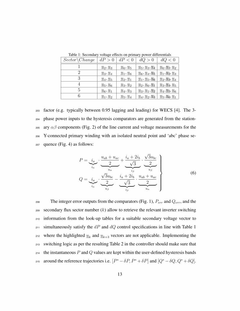
Table 1: Secondary voltage effects on primary power differentialsSector\Change dP > 0 dP < 0 dQ > 0 dQ < 0
1 u2, u3 u6, u5 u5, u3,u4 u6,u1, u22 u3, u4 u1, u6 u6, u4,u5 u1,u2, u33 u4, u5 u2, u1 u1, u5,u6 u2,u3, u44 u5, u6 u3, u2 u2, u6,u1 u3,u4, u55 u6, u1 u4, u3 u3, u1,u2 u4,u5, u66 u1, u2 u5, u4 u4, u2,u3 u5,u6, u1
factor (e.g. typically between 0.95 lagging and leading) for WECS [4]. The 3-203
phase power inputs to the hysteresis comparators are generated from the station-204
ary αβ components (Fig. 2) of the line current and voltage measurements for the205
Y-connected primary winding with an isolated neutral point and ‘abc’ phase se-206
quence (Fig. 4) as follows:207
P = ia︸︷︷︸iα
· uab + uac2︸ ︷︷ ︸uα
+ia + 2ib√
3︸ ︷︷ ︸iβ
·√
3ubc2︸ ︷︷ ︸uβ
Q = ia︸︷︷︸iα
·√
3ubc2︸ ︷︷ ︸uβ
− ia + 2ib√3︸ ︷︷ ︸
iβ
· uab + uac2︸ ︷︷ ︸uα
(6)
The integer error outputs from the comparators (Fig. 1), Perr andQerr, and the208
secondary flux sector number (k) allow to retrieve the relevant inverter switching209
information from the look-up tables for a suitable secondary voltage vector to210
simultaneously satisfy the dP and dQ control specifications in line with Table 1211
where the highlighted uk and uk+3 vectors are not applicable. Implementing the212
switching logic as per the resulting Table 2 in the controller should make sure that213
the instantaneous P andQ values are kept within the user-defined hysteresis bands214
around the reference trajectories i.e. [P ∗− δP, P ∗ + δP ] and [Q∗− δQ,Q∗ + δQ].215
13

Table 2: Inverter switching vectorsPowerDeviations Sector(k)
P ∗ − P Q∗ −Q 1 2 3 4 5 6≤ −δP > δQ u5 u6 u1 u2 u3 u4≤ −δP ≤ −δQ u6 u1 u2 u3 u4 u5> δP > δQ u3 u4 u5 u6 u1 u2> δP ≤ −δQ u2 u3 u4 u5 u6 u1
Table 3: Anticipated ∆Q sign (±) | Flux sector increments (±1)k u1 u2 u3 u4 u5 u61 −| − 1 +|+ 1 +| − 1 −|+ 12 −|+ 1 −| − 1 +|+ 1 +| − 13 +| − 1 −|+ 1 −| − 1 +|+ 14 +| − 1 −|+ 1 −| − 1 +|+ 15 +|+ 1 +| − 1 −|+ 1 −| − 16 −| − 1 +|+ 1 +| − 1 −|+ 1
3.3. Secondary flux sector ascertainment216
One of the principal strengths of the proposed HPQC over DTC is a unique217
λs sector identification technique, which is not founded on the λs estimation or218
its absolute position knowledge, but on monitoring the measurable incremental219
changes ofQ (∆Q) instead. On these grounds, it is essentially indirect in principle220
and allows entirely parameter independent sensorless power control.221
Commencing with the case study considered in Fig. 4 as an initial λs sector222
condition and looking at the possible voltage-sector combinations from Tables 2223
and 3, if u2 or u6 are applied then ∆Q < 0 (i.e. ‘-’ in Table 3), else u3 or u5 are224
the secondary terminal voltages and ∆Q > 0 (i.e. ‘+’ in Table 3). So, as long225
as the predictions in the ∆Q sign (Table 3) are coincident with the calculations226
obtained from measurements using (6), no control action for the sector transition227
14

should be taken. Otherwise, any disagreement in the results may suggest that228
an unknown machine speed mode reliant sector change has occurred, and that229
the sector counter is to be updated by ±1 as λs can’t instantly ‘jump’ through230
the sectors. At super-synchronous speeds, the λs rotating counter-clockwise goes231
to sector 2 where u3 and u6 have completely different effects on ∆Q than in232
sector 1, causing a sudden alteration of the ∆Q sign and hence the sector number.233
Similarly, for sub-synchronous speed operation and clockwise rotation of λs, u2234
and u5 are the two pointing vectors to a sector change from 1 to 6.235
4. Experimental verification236
The HPQC scheme was implemented on a dSPACEr control prototyping plat-237
form of a custom-made test rig (Fig. 5) for a 6/2-pole BDFRG with both windings238
rated at 415 V, 2.5 A, 50 Hz. The two-level voltage source inverter is a Semikronr239
smart power IGBT module (Skiipr). A commercial four-quadrant Parkerr DC240
drive emulated the chosen prime mover (e.g. wind turbine) characteristics of the241
BDFRG as explained in [36]. The remaining machine data and details of the appa-242
ratus used for testing can be found in [30]. The system sampling rate was 10 kHz,243
and the variable switching frequency was around 5 kHz. The hysteresis bands244
were set to δP = 50 W and δQ = 100 VAr.245
The BDFRG is self-started as a wound rotor induction machine to the steady246
no-load speed (Fig. 6). The inverter was then enabled, and the HPQC viability247
proven by laboratory tests for three ordinary speed set-points in a narrow range248
down to synchronous speed for step-changes in P ∗ and/or Q∗ settings. An incre-249
mental encoder was used for instrumentation purposes and to provide feedback to250
the DC drive to maintain the desired shaft speed externally as the prime objective251
15

Figure 5: A photo of the BDFRG test facility used for experimental studies.
was to evaluate the algorithm in power mode. In a real WECS with HPQC, this252
sensor would only serve to generate the necessary P ∗ for MPPT [1] as depicted in253
Fig. 1. Sensorless MPPT options are also possible [37].254
4.1. Open-loop speed control255
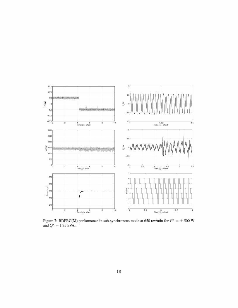
The P step response in Fig. 7 demonstrates the high HPQC performance with256
a smooth and swift changeover from BDFRM to BDFRG operation. For instance,257
such mode reversals, whilst not so rapid, are encountered with reversible pump-258
turbine devices for load balancing in pumped-storage hydro-power plants [38, 39].259
The correspondingQ trace shows little or no apparent signs of cross-coupling per-260
taining to this transition, such as level shifting or other steady-state disturbances.261
A short speed dip comes from the sudden load increase perceived by the DC ma-262
chine when the BDFRG starts generating P . For a given Q∗, the primary current263
(ia) is virtually unaffected by the P transient with its largely magnetizing nature,264
16

Figure 6: Oscillograms of the recorded steady-state currents in two phases of the shorted secondarywinding for the unloaded BDFRG at ≈ 730 rev/min.
and hence the fairly uniform magnitudes throughout at line frequency2. However,265
the peak secondary currents (isa), as predominantly torque producing, get higher266
to accommodate the rise of Te and Pm required to cover the BDFRG losses in267
delivering the same P as consumed for the BDFRM operation. Moreover, from268
(2), the secondary frequency (fs) should be -6.67 Hz at 650 rev/min, which can269
be found indeed true by counting ≈ 17 150 ms cycles over 2.5 s on the measured270
isa waveform. The last graph in Fig. 7 shows the descending sector changes of the271
clockwise rotating λs as ‘fs < 0’ (Figs. 2 and 4).272
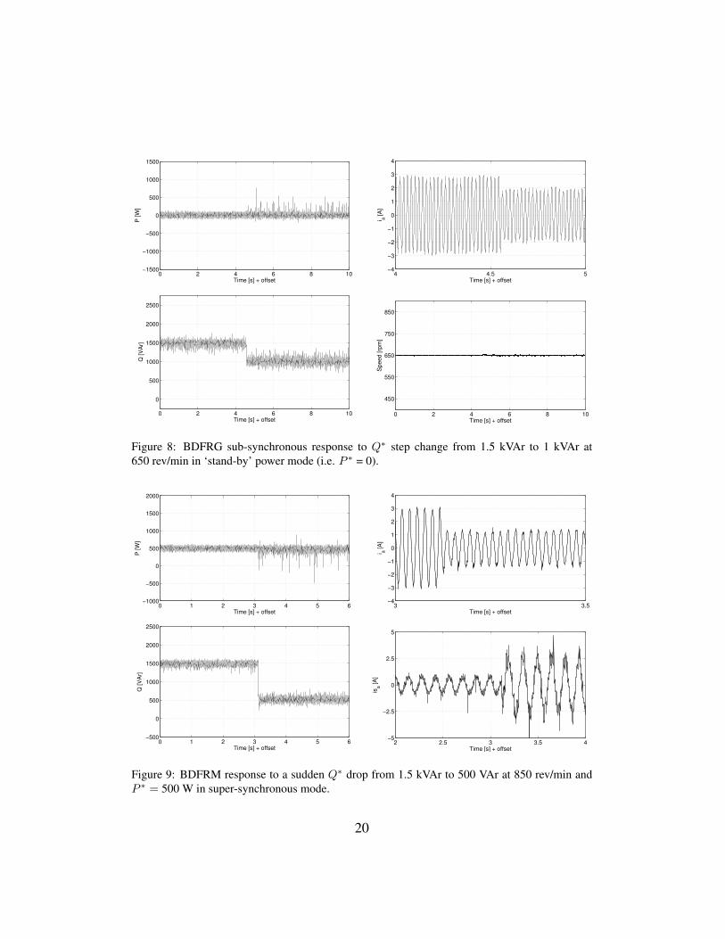
The results in Fig. 8 are complementary to those in Fig. 7. The HPQC proper-273
ties for a stepping-down Q∗ and the ‘idling’ machine playing an inductive role are274
2There are 25 sine waves, each of 20 ms in period (i.e. fp = 50 Hz), over a 0.5 s time intervalon the respective zoomed-in sub-plot of Fig. 7.
17
0 2 4 6 8 10−1500
−1000
−500
0
500
1000
1500
Time [s] + offset
P [W
]
4 4.25 4.5−5
0
5
−2.5
2.5
Time [s] + offseti a
[A
]
0 2 4 6 8 100
500
1000
1500
2000
2500
3000
Time [s] + offset
Q [V
Ar]
3 3.5 4 4.5 5 5.5−5
0
5
−2.5
2.5
Time [s] + offset
isa [
A]
0 2 4 6 8 10
450
550
650
750
850
Time [s] + offset
Speed [rp
m]
2 2.5 3 3.5 40
1
2
3
4
5
6
7
Time [s] + offset
Se
cto
r
Figure 7: BDFRG(M) performance in sub-synchronous mode at 650 rev/min for P ∗ = ± 500 Wand Q∗ = 1.35 kVAr.
18

examined now. Albeit not practical, this is an extremely insightful and challeng-275
ing scenario from a control perspective as the current in either winding is then276
mostly reactive allowing the effects of varying Q∗ to be investigated separately277
from P . The power plots in Fig. 8 are another evidence of robust and decoupled278
control, although fast transients may be superfluous for the BDFRG target appli-279
cations. Unlike Fig. 7, the shaft speed is barely influenced by the Q∗ change as280
expected for an unloaded machine, whereas the ia amplitudes exhibit a foreseen281
decline with theQ reduction. The magnetizing isa will thus increase in magnitude282
in much the same manner as it does in Fig. 7.283
The measurements in Fig. 9 reinforce the controller’s ability to successfully284
track the stipulated Q∗ trajectory, and its capacity to instantly react to an even285
doubled step-change of Q∗ than in Fig. 8. More importantly, the mid P value286
doesn’t seem to be impaired in any way by such a big Q perturbation. The ia287
has notably decreased, and the isa , taking over the machine magnetization from288
the primary winding increased, in magnitude nearly in the same proportion as the289
Q level has diminished with the power factor improvement indicating the mainly290
flux producing share of both the currents.291
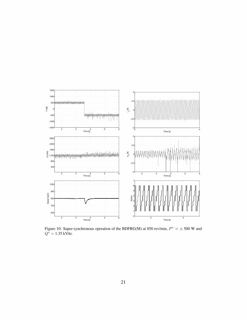
The majority of the HPQC observations and/or explanations of the physical292
phenomena behind the performance measures in Fig. 7 can be extended to those293
in Fig. 10. An exception is that the λs sector numbers are now in ascending order294
with the counter-clockwise rotation of the secondary vectors, which is contrary to295
the sub-synchronous case in Fig. 7. By analogy to the latter, the presence of ≈ 30296
cycles on the isa waveform in Fig. 10 during 4.5 s implies the same fs of 6.67 Hz297
at 850 rev/min and 650 rev/min but with the opposite phase sequence (i.e. sign).298
Much the same HPQC features can be discovered from Fig. 11. Either Q or P299
19
0 2 4 6 8 10−1500
−1000
−500
0
500
1000
1500
Time [s] + offset
P [W
]
4 4.5 5−4
−3
−2
−1
0
1
2
3
4
Time [s] + offset
i a [
A]
0 2 4 6 8 10
0
500
1000
1500
2000
2500
Time [s] + offset
Q [V
Ar]
0 2 4 6 8 10
450
550
650
750
850
Time [s] + offset
Sp
ee
d [
rpm
]
Figure 8: BDFRG sub-synchronous response to Q∗ step change from 1.5 kVAr to 1 kVAr at650 rev/min in ‘stand-by’ power mode (i.e. P ∗ = 0).
0 1 2 3 4 5 6−1000
−500
0
500
1000
1500
2000
Time [s] + offset
P [W
]
3 3.5−4
−3
−2
−1
0
1
2
3
4
Time [s] + offset
i a [
A]
0 1 2 3 4 5 6−500
0
500
1000
1500
2000
2500
Time [s] + offset
Q [V
Ar]
2 2.5 3 3.5 4−5
0
5
−2.5
2.5
Time [s] + offset
isa [
A]
Figure 9: BDFRM response to a sudden Q∗ drop from 1.5 kVAr to 500 VAr at 850 rev/min andP ∗ = 500 W in super-synchronous mode.
20
2 3 4 5 6−1500
−1000
−500
0
500
1000
1500
Time [s]
P [W
]
3 4−5
0
5
−2.5
2.5
Time [s]
i a [
A]
2 3 4 5 6
350
850
1,350
1850
2350
2850
Time [s]
Q [V
Ar]
2 3 4 5 6−5
0
5
−2.5
2.5
Time [s]
isa [
A]
2 3 4 5 6
650
750
850
950
1050
Time [s]
Speed [rp
m]
2 30
1
2
3
4
5
6
7
Time [s]
Se
cto
r
Figure 10: Super-synchronous operation of the BDFRG(M) at 850 rev/min, P ∗ = ± 500 W andQ∗ = 1.35 kVAr.
21

responses appear to be insensitive (in average terms) to the step-down change of300
P ∗ not experiencing any visible form of disruption. The speed glitch in Fig. 11 is301
less pronounced than in Fig. 7 because of the smaller P ∗ deviation to handle by302
the PI speed regulator of the DC drive.303
4.2. Machine design vs performance trade-offs304
Noise susceptibility and higher current ripples are common with hysteresis305
control by its ‘bang-bang’ complexion. This issue is more aggravated for the306
considered HPQC with the non-optimal design of the proof-of-concept BDFRG.307
The latest finite-element-analyses [40] have established the drawbacks of 6/2 pole308
winding arrangements with an axially-laminated rotor in terms of the presence of309
low-order harmonics and modest power density, identifying the 8/4 pole wound310
stators and modern radially-laminated ducted reluctance rotors as the way for-311
ward. The former limitation can clearly be attributed to our prototype judging by312
the visibly ripple-corrupted is waveforms even without switching power electron-313
ics in Fig. 6 and manifesting also in Figs. 7, 9 and 10 for the controlled machine.314
Similar distortions, though incomparably less pronounced with the weak mag-315
netic coupling between the windings, can be seen in the much cleaner primary ia316
currents but only at higher is levels in Fig. 9. Furthermore, the unusually large317
Rs ≈ 13 Ω contravenes the main HPQC assumption of negligible voltage drops318
causing modeling and control inaccuracies as es, and not us, dictates dλs/dt given319
(1). This is predominantly the case with increasing is amplitudes as can be seen in320
the spiky P , and foremost Q, responses (Figs. 7, 9 and 10) or at lower Q∗ require-321
ments (Figs. 8, 9 and 11). Finally, the secondary winding is not appropriately322
rated to accomplish close to unity primary power factor without tripping of the323
over-current protection.324
22

0 1 2 3 4 5−1500
−1000
−500
0
500
1000
1500
Time [s] + offset
P [
W]
0 1 2 3 4 5−500
0
500
1000
1500
2000
2500
Time [s] + offset
Q [
VA
r]
0 1 2 3 4 5500
600
700
800
900
1000
Time [s] + offset
Spe
ed
[rp
m]
Figure 11: BDFRM synchronous operation at 750 rev/min for P ∗ varying from 500 W to 0 W at1.3 kVAr.
23

5. Conclusions325
A robust, machine parameter-free HPQC algorithm for the BDFRG has been326
suggested and successfully experimentally validated by the results presented. Orig-327
inating from the basic electro-magnetic relationships for doubly-excited machines328
renders it versatile and potentially suitable to any member of this family. These329
virtues, coupled with the computational effectiveness and ease of implementation,330
offer superior performance to the existing DT(P)C methods and could strengthen331
the HPQC standing as a viable competitor of model-based or PI control strategies.332
A good overall response and disturbance rejection abilities of both the P and333
Q sub-controllers have been verified on the early small-scale prototype despite the334
challenging test conditions imposed by its high winding resistances and crude de-335
sign. The adverse resistive effects and control deterioration at low secondary volt-336
ages and frequencies over a narrow speed range have been mitigated by omitting337
the two zero-vectors in the inverter switching strategy being applied. The accom-338
panying speed mode reliance and emanating complexities of the HPQC scheme,339
that would have been otherwise introduced, had been avoided as an added bonus.340
A significant performance enhancement would be envisaged with larger, more341
representative machines having much smaller resistances.342
The above merits, along with the rotor position and velocity independence,343
form a basis for facilitated sensorless HPQC of WECS, or the use of a low to344
medium resolution sensor, as very accurate estimates or high-bandwidth mea-345
surements of the shaft speed are not imperative for MPPT in these applications.346
Finally, given the conceptual similarities with the DTC, the HPQC may draw at-347
tention of industrial companies like ABB with its existing production line of DTC348
power converters (e.g. the ACS800 series) for DFIG and other MW wind turbines.349
24
References350
[1] M. Cheng, Y. Zhu, The state of the art of wind energy conversion systems351
and technologies: A review, Energy Conversion and Management 88 (2014)352
332–347.353
[2] R. Cardenas, R. Pena, S. Alepuz, G. Asher, Overview of control systems for354
the operation of DFIGs in wind energy applications, IEEE Transactions on355
Industrial Electronics 60 (7) (2013) 2776–2798.356
[3] J. Carroll, A. McDonald, D. McMillan, Reliability comparison of wind tur-357
bines with DFIG and PMG drive trains, IEEE Transactions on Energy Con-358
version 30 (2) (2015) 663–670.359
[4] J. G. Njiri, D. Soffker, State-of-the-art in wind turbine control: Trends and360
challenges, Renewable and Sustainable Energy Reviews 60 (2016) 377–393.361
[5] J. Mohammadi, S. Afsharnia, S. Vaez-Zadeh, Efficient fault-ride-through362
control strategy of DFIG-based wind turbines during the grid faults, Energy363
Conversion and Management 78 (2014) 88–95.364
[6] S. Tohidi, P. Tavner, R. McMahon, H. Oraee, M. Zolghadri, S. Shao, E. Abdi,365
Low voltage ride-through of DFIG and brushless DFIG: Similarities and dif-366
ferences, Electric Power Systems Research 110 (2014) 64–72.367
[7] A. Rahim, E. Nowicki, Supercapacitor energy storage system for fault ride-368
through of a DFIG wind generation system, Energy Conversion and Man-369
agement 59 (2012) 96–102.370
25
[8] K. Vinothkumar, M. Selvan, Novel scheme for enhancement of fault ride-371
through capability of doubly fed induction generator based wind farms, En-372
ergy Conversion and Management 52 (7) (2011) 2651–2658.373
[9] S. Tohidi, B. Mohammadi-ivatloo, A comprehensive review of low voltage374
ride through of doubly fed induction wind generators, Renewable and Sus-375
tainable Energy Reviews 57 (2016) 412–419.376
[10] H. Zeng, Y. Zhu, J. Liu, Verification of DFIG and PMSG wind turbines’377
LVRT characteristics through field testing, in: Power System Technology378
(POWERCON), 2012 IEEE International Conference on, 2012, pp. 1–6.379
[11] A. Oraee, E. Abdi, S. Abdi, R. McMahon, P. Tavner, Effects of rotor winding380
structure on the BDFM equivalent circuit parameters, IEEE Transactions on381
Energy Conversion 30 (4) (2015) 1660–1669.382
[12] A. Knight, R. Betz, D. Dorrell, Design and analysis of brushless doubly383
fed reluctance machines, IEEE Transactions on Industry Applications 49 (1)384
(2013) 50–58.385
[13] E. Abdi, R. McMahon, P. Malliband, S. Shao, M. Mathekga, P. Tavner,386
S. Abdi, A. Oraee, T. Long, M. Tatlow, Performance analysis and testing387
of a 250 kW medium-speed brushless doubly-fed induction generator, IET388
Renewable Power Generation 7 (6) (2013) 631–638.389
[14] F. Wang, F. Zhang, L. Xu, Parameter and performance comparison of390
doubly-fed brushless machine with cage and reluctance rotors, IEEE Trans-391
actions on Industry Applications 38 (5) (2002) 1237–1243.392
26
[15] R. Zhao, A. Zhang, Y. Ma, X. Wang, J. Yan, Z. Ma, The dynamic control of393
reactive power for the brushless doubly fed induction machine with indirect394
stator-quantities control scheme, IEEE Transactions on Power Electronics395
30 (9) (2015) 5046–5057.396
[16] S. Abdeddaim, A. Betka, S. Drid, M. Becherif, Implementation of MRAC397
controller of a DFIG based variable speed grid connected wind turbine, En-398
ergy Conversion and Management 79 (2014) 281–288.399
[17] J. Chen, W. Zhang, B. Chen, Y. Ma, Improved vector control of brush-400
less doubly fed induction generator under unbalanced grid conditions for401
offshore wind power generation, IEEE Transactions on Energy Conversion402
31 (1) (2016) 293–302.403
[18] I. Sarasola, J. Poza, M. A. Rodriguez, G. Abad, Direct torque control design404
and experimental evaluation for the brushless doubly fed machine, Energy405
Conversion and Management 52 (2) (2011) 1226–1234.406
[19] H. Chaal, M. Jovanovic, Toward a generic torque and reactive power con-407
troller for doubly fed machines, IEEE Transactions on Power Electronics408
27 (1) (2012) 113–121.409
[20] F. Zhang, L. Zhu, S. Jin, W. Cao, D. Wang, J. L. Kirtley, Developing a new410
SVPWM control strategy for open-winding brushless doubly fed reluctance411
generators, IEEE Transactions on Industry Applications 51 (6) (2015) 4567–412
4574.413
[21] L. Xu, B. Guan, H. Liu, L. Gao, K. Tsai, Design and control of a high-414
efficiency doubly-fed brushless machine for wind power generator applica-415
27

tion, in: 2010 IEEE Energy Conversion Congress and Exposition, 2010, pp.416
2409–2416.417
[22] D. G. Dorrell, M. Jovanovic, On the possibilities of using a brushless doubly-418
fed reluctance generator in a 2 MW wind turbine, IEEE Industry Applica-419
tions Society Annual Meeting (2008) 1–8.420
[23] F. Valenciaga, Second order sliding power control for a variable speed-421
constant frequency energy conversion system, Energy Conversion and Man-422
agement 52 (12) (2010) 3000–3008.423
[24] M. G. Jovanovic, J. Yu, E. Levi, Encoderless direct torque controller for424
limited speed range applications of brushless doubly fed reluctance motors,425
IEEE Transactions on Industry Applications 42 (3) (2006) 712–722.426
[25] M. Jovanovic, Sensored and sensorless speed control methods for brushless427
doubly fed reluctance motors, IET Electric Power Applications 3 (6) (2009)428
503–513.429
[26] H. Chaal, M. Jovanovic, Practical implementation of sensorless torque and430
reactive power control of doubly fed machines, IEEE Transactions on Indus-431
trial Electronics 59 (6) (2012) 2645–2653.432
[27] H. Chaal, M. Jovanovic, Power control of brushless doubly-fed reluctance433
drive and generator systems, Renewable Energy 37 (1) (2012) 419–425.434
[28] S. Ademi, M. Jovanovic, High-efficiency control of brushless doubly-fed435
machines for wind turbines and pump drives, Energy Conversion and Man-436
agement 81 (2014) 120–132.437
28

[29] S. Ademi, M. Jovanovic, M. Hasan, Control of brushless doubly-fed reluc-438
tance generators for wind energy conversion systems, IEEE Transactions on439
Energy Conversion 30 (2) (2015) 596–604.440
[30] S. Ademi, M. Jovanovic, Control of doubly-fed reluctance generators for441
wind power applications, Renewable Energy 85 (2016) 171–180.442
[31] S. Ademi, M. Jovanovic, Control of emerging brushless doubly-fed re-443
luctance wind turbine generators, in: J. Hossain, A. Mahmud (Eds.),444
Large Scale Renewable Power Generation, Green Energy and Technology,445
Springer Singapore, 2014, pp. 395–411.446
[32] S. Ademi, M. G. Jovanovic, H. Chaal, W. Cao, A new sensorless speed con-447
trol scheme for doubly fed reluctance generators, IEEE Transactions on En-448
ergy Conversion 31 (3) (2016) 993–1001.449
[33] S. Ademi, M. Jovanovic, A novel sensorless speed controller design for450
doubly-fed reluctance wind turbine generators, Energy Conversion and Man-451
agement 120 (2016) 229–237.452
[34] S. Ademi, M. Jovanovic, Vector control methods for brushless doubly fed453
reluctance machines, IEEE Transactions on Industrial Electronics 62 (1)454
(2015) 96–104.455
[35] R. E. Betz, M. G. Jovanovic, Introduction to the space vector modelling of456
the brushless doubly-fed reluctance machine, Electric Power Components457
and Systems 31 (8) (2003) 729–755.458
29
[36] H. Camblong, I. M. de Alegria, M. Rodriguez, G. Abad, Experimental eval-459
uation of wind turbines maximum power point tracking controllers, Energy460
Conversion and Management 47 (18-19) (2006) 2846–2858.461
[37] W. Lin, C. Hong, F. Cheng, Design of intelligent controllers for wind gen-462
eration system with sensorless maximum wind energy control, Energy Con-463
version and Management 52 (2) (2011) 1086–1096.464
[38] J. I. Sarasua, J. I. Perez-Diaz, J. R. Wilhelmi, J. Angel Sanchez-Fernandez,465
Dynamic response and governor tuning of a long penstock pumped-storage466
hydropower plant equipped with a pump-turbine and a doubly fed induction467
generator, Energy Conversion and Management 106 (2015) 151–164.468
[39] N. Sivakumar, D. Das, N. Padhy, Variable speed operation of reversible469
pump-turbines at Kadamparai pumped storage plant - a case study, Energy470
Conversion and Management 78 (2014) 96–104.471
[40] T. Staudt, F. Wurtz, L. Gerbaud, N. J. Batistela, P. Kuo-Peng, An472
optimization-oriented sizing model for brushless doubly fed reluctance ma-473
chines: Development and experimental validation, Electric Power Systems474
Research 132 (2016) 125–131.475
30