
WILDERNESS ROPE RESCUE OPERATIONS - RAT-SAR
165
© Copyright 2020 RAT-SAR WILDERNESS ROPE RESCUE OPERATIONS FOR THE WILDERNESS SAR TECHNICIAN
Transcript of WILDERNESS ROPE RESCUE OPERATIONS - RAT-SAR

© Copyright 2020 RAT-SAR
WILDERNESS ROPE RESCUE OPERATIONS
FOR THE WILDERNESS SAR TECHNICIAN

COURSE OVERVIEW
• This is an operations level course designed to merge standard rescue practices with techniques found in mountaineering, caving, canyoneering and lightweight rescue. It is designed to teach a wilderness search technician proficiency in rope rescue techniques, so the searcher can become the rescuer.
• Although NFPA standards are discussed, this course is not designed to be NFPA compliant.
• Minimum time requirements for this course: 40 hours (classroom and field training exercises).
• Upon satisfactory completion of this course and all Job Performance Requirements, the student will receive a certificate of completion for Wilderness Rope Rescue, Operations Level.
• Suggested prerequisites: ICS-100, ICS-700, Wilderness First Aid, NASAR SARTECH II, ASTM 2209-14, or North Carolina LSFTM (Land Search Field Team Member).

PROFICIENCY LEVELS
1) Awareness Level: This level represents the minimum capability to provide response to technical search and rescue incidents. It’s a basic understanding of technical rope rescue.
2) Operations Level: This level represents the capability to respond to technical search and rescue incidents and to identify hazards, use rescue equipment, and apply limited techniques.
3) Technician Level: This level represents the capability to respond to technical search and rescue incidents and to identify hazards, use rescue equipment, and apply advanced techniques necessary to coordinate, perform and supervise technical search and rescue incidents.
4) Advanced Technician: This level represents an understanding in the physics and science behind technical rope rescue systems, highlines, and advanced horizontal systems. The advanced technician may also show proficiency in experimenting, developing and testing new technical rescue concepts.

• Safety
• Equipment
• Knots
• Anchors
• Single Rope Descending
• Single Rope Ascending
• Belays / Safeties
• Pick-Off Rescues
• Dual Tension Lowering / Raising Systems
• Mechanical Advantage
• System Changeovers
• Knot Passes
• Litters / Patient Packaging
• High Directionals
THIS COURSE CONSISTS OF:

• Locking Carabiners (HMS Style Preferred)
• Descent Control Device
• Ascending System
• 6mm Prusik Cords (long and short)
• Class II Harness
• Helmet
• Gloves
• Helmet Light
STUDENT MINIMAL EQUIPMENT REQUIREMENTS
Lifelines used in this course range from 8.5 to 9.5mm.

• 6 ea. HMS Locking Carabiners
• 1 ea. ATC Guide
• 2 ea. 6mm Prusik Loops (long)
• 2 ea. 6mm Prusik Loops (short)
• 1 ea. 30’ Body Cord (8mm)
• 1 ea. Dyneema Sling (120cm)
• 1 ea. Single Sheave Rescue Pulley
• Ascending System
• Class II Harness
• Helmet
• Gloves
• Helmet Light
SUGGESTED LIGHTWEIGHT RESCUER GEAR
If all rescuers on a lightweight rescue team carry the same gear, then advanced and complex systems can be built by combing the available gear.

Day 1: Safety, Equipment, Knots, Anchors
Day 2: Rescuer Descending & Lowering / Ascending
Day 3: Mechanical Advantage, Pick-Off Rescues
Day 4: Litters/ Patient Packaging, Dual Tension Raises & Lowers, Changeovers, Knot Passes
Day 5: High Directionals, Gin Poles, Advanced Anchors
ITENERARY

EXPECTATIONS OF WILDERNESS RESCUE TECHNICIANS

THIS PAGE INTENTIONALLY LEFT BLANK

© Copyright 2020 RAT-SAR
WILDERNESS ROPE RESCUE OPERATIONS
Background, Safety, Equipment, Knots, Anchors

L.A.S.T.
L - LocateA - AssessS - StabilizeT - Transport
CONCEPT OF SEARCH and RESCUE
DO NO MORE HARM!
Our role as SAR
technicians.
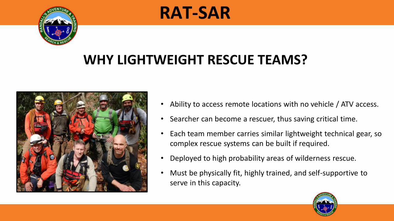
• Ability to access remote locations with no vehicle / ATV access.
• Searcher can become a rescuer, thus saving critical time.
• Each team member carries similar lightweight technical gear, so complex rescue systems can be built if required.
• Deployed to high probability areas of wilderness rescue.
• Must be physically fit, highly trained, and self-supportive to serve in this capacity.
WHY LIGHTWEIGHT RESCUE TEAMS?

WILDERNESS LIGHTWEIGHT SCENARIOS
• Searchers deployed to areas requiring technical rope skills to effectively the search area.
• Injured climber / rappeler on rope (conscience or unconscious) in remote areas.
• Injured or non-injured person trapped in a confined space or hazardous terrain.
• Falls in a remote vertical or steep environment.
• Short Roped (rope doesn’t reach the bottom and climber can’t get back up the rope).
• Climber stuck on a rope due to equipment failure or jams.
• Un-roped hiker/climber stuck on a ledge or high point.
• Injured hiker requiring evacuation in mid to steep terrain.
• Equipment problems / failures.
• Recovery operations in remote and technical wilderness environments.

OPERATING SAFELY
• Learning the skills (Getting the basics down correctly).
• System setup (Use the proper equipment without weak links).
• Checking (Always double check to prevent mistakes).
• Belaying / Redundancy / Safeties.

DUNNING – KRUGER EFFECT
Creating false reality from the perception of the input that ultimately leads people with a low ability for a task to overestimate their ability. In short: we don’t know what we don’t know. Over confidence without experience kills.

RESCUER SAFETY
• Work a buddy system.
• Speak up, regardless of your skill level.
• Use the “Touch” system to verify all rigging.
• Never use questionable equipment.
• Always use a safety line when working close to the edge.
• Always consider your safety factor.
• The rescuer’s safety comes first!

SAFETY OFFICER and TEAM LEADER
• The Safety Officer’s job is to ensure the system and individuals are safe before operations begin, during operations and during site cleanup.
• The Team Leader is responsible for operations and delegating tasks at the scene.
Every rescuer on a wilderness rescue team is considered a safety officer.

SAFETY OFFICER DUTIES
• Survey the scene for hazards and work with the team leader to establish safe fall lines.
• Designate safe areas / zones.
• Double check rescuers’ PPE before the operation begins.
• Verify the system is built properly.
• Verify edge protection (if required).
• Verify all carabiners are locked and properly oriented.
• Verify prusiks / progress captures are properly tied and placed on the lifelines.
• Verify safety lines.

ZONES
• COLD ZONE: Area for incident support operations.
• WARM ZONE: Area where support of the technical rescue operation is attended to. Hauling personnel or others who may help when called upon will be located here.
• HOT ZONE: Participation in the hot zone should be by "invitation only" and be limited to those personnel whose duties and responsibilities are directly related to the safe setup, operation, and breakdown of rescue systems. The rescue group leader, hot zone safety officer, hauling boss, rigging master, and rescue group support personnel are located in the hot zone.
If you have no business to be in a particular zone, don’t be!

STANDARDS
The standard that many technical rescue organizations adhere to are created and maintained by the NFPA (National Fire Protection Association). The NFPA is not a government agency, thus it has no enforcement powers over compliance to a standard. The Authority Having Jurisdiction (AHJ) is the enforcement arm of standards and certifications.
This course is not an NFPA compliant course. NFPA standards are being discussed for information purposes only.

NFPA 1983
• NFPA 1983 is a manufacturing standard for ropes, auxiliary equipment and harnesses.
• The standard specifies to the manufacturer how the item is to be designed, its strength requirements, testing and labeling requirements.
• For the item to carry the 1983 certification, the manufacturer must adhere to these standards.
• Most rescue teams strive to acquire 1983 compliant rescue gear, however this standard does not require any team or individual to use gear manufactured to NFPA 1983 standards.

NFPA 1006
• The purpose of this standard is to specify the minimum JPRs (Job Performance Requirements) for service as a technical rescuer.
• This standard applies to other specialties as a rescuer, including swift water rescue, wilderness rescue and ten other specialties in its current format. All specialties include two levels of qualification: Level I and Level II.
• Level I applies to “individuals who identify hazards, use equipment, and apply limited techniques specified in this standard to perform technical rescue operations.”
• Level II applies to “individuals who identify hazards, use equipment, and apply advanced techniques specified in this standard to perform technical rescue operations.”
NFPA 1670
• The purpose of NFPA 1670 is to assist the Authority Having Jurisdiction (AHJ) to assess a technical search and rescue hazard within the response area, identify the level of operational capability, and establish operational criteria.
• This standard applies to agencies and not individuals, so it is the standard that an agency (AHJ) complies with. By having its individual rescuers trained to the NFPA 1006 Technical Rescuer Professional Qualifications, the AHJ is completing part of the overall requirement to comply with NFPA 1670.

STANDARDS and CERTIFICATION
The accepted standards and certification processes for a rope rescue technician are governed by the Authority Having Jurisdiction (AHJ).
The paper means nothing unless your AHJ accepts and recognizes the certification.

PERSONAL PROTECTIVE EQUIPMENT
• Helmet• Harness• Gloves• Eye Protection• Cutting Tool?
When working around load bearing ropes, knives and shears should ONLY be deployed as last-ditch tools. It is imperative you verify what you are cutting so you do not accidentally cut a lifeline.

HARNESS TYPES
Class 1*
Class II
Class III
* Class 1 no longer listed in 1983. Now considered escape or hasty harnesses.
Hasty Harness
Class II is the most common harness used in Lightweight Rescue.

EQUIPMENT
Remember, your life is supported by the weakest link in the chain. Never buy used equipment!

SAFETY FACTOR
• Safety factor is the minimum breaking strength (MBS) divided by the maximum force expected to be applied. Example: a carabiner rated for 5,000 lbf (22.2 kN) MBS with a 1000-pound load suspended from it has a safety factor of 5:1.
• How a piece of equipment is used will affect the MBS it is rated at. A knot tied in a rope decreases its MBS considerably. Side loading, tri-axial loading or torque loading a carabiner lowers its minimum breaking strength.
• An acceptable safety factor should be decided on by the AHJ governing the use of lightweight teams and techniques.

STATIC SYSTEM SAFETY FACTOR
A rope system should be thought of as a chain that will break at its weakest link. Loads and stresses will be different on each component depending on where it’s placed or how it’s used in the system. Each link should be analyzed for its safety factor in relation to the job it’s performing. Calculation of the weakest link will give you the theoretical Static System Safety Factor (SSSF).

DYNAMIC SYSTEMS SAFETY FACTOR
• Since rope rescue systems move, the forces applied to them will change from static (sitting still) to dynamic forces.
• Dynamic forces can be much higher on the overall system.
• DSSF is much harder to calculate than SSSF due to the variable factors involved. Example: how smooth a haul team operates the system will directly effect how much dynamic force gets applied to the system as the load is raised.

FALL FACTOR and SHOCK LOADING
• Fall Factor (FF) equals the distance of the fall (D) divided by the length of the rope used in the system (L) from the load to the anchor. FF=D/L
• The higher the fall factor, the greater the potential force (shock load) applied to the system.
• There are numerous factors that governor potential shock load: fall factor, rope stretch (elongation), friction in the system, loads, rope lengths, etc.
• Example: A 176 Lb. load dropped 2’ on a 4’ static rope (.5 FF) generates over 1500 pounds of force on the system and the patient.
Anchor
SAFETY FACTOR SOGs
• Varies between agencies.
• Often misunderstood – not dictated by a standard such as NFPA.
• Will typically be lower for lightweight teams such as mountain rescue.
• Actual safety factor can be raised by eliminating the potential for shock loading and dynamic events.
• Actual safety factor can be raised by reducing the load on the system.
• To simplify safety factor calculations, consider a single person load as 1 kN.

ROPE RESCUE SYSTEM ANALYSIS
• CRITICAL POINT ANALYSISWhere / what is the weakest link in the system?
What are the redundancies and backups if a system fails?
ROPE, CORDAGE & WEBBING
• Static Kernmantle (typically less than 6% elongation)
• Dynamic Kernmantle (typically above 6% elongation)
• 1 Inch Flat & Tubular Webbing
• High Tenacity Cords and Dyneema Slings
• The most commonly used SRT and rescue rope is 7/16” (11mm) and 1/2” (13mm) diameter Static Kernmantle certified by the National Fire Protection Association (NFPA) 1983 Standard For Technical (or General) Rope Use. NFPA Technical Use is rated at no less than 20kN. NFPA General Use is rated at no less than 40kN.
• NFPA Technical Use is rated for one person loads at a 15:1 safety factor. NFPA General use is rated for two person loads with a 15:1 safety factor (one-person loads are considered to be 300 pounds and two-person load are considered 600 pounds).
• Wilderness rescue rope sizes and ratings will vary depending on the application and agreed upon safety factors. 9mm is becoming an acceptable size for lightweight rescue applications.

ROPE, CORDAGE & WEBBING
Average Load Ratings Per Size (depending on manufacturer and type):
8.0mm (5/16) – 15 kN or 3500 Lbs. (Used for rescuer body cord)9.0mm (3/8) – 20 kN or 4500 Lbs. (Typical rope size for some lightweight teams)11.1mm (7/16) – 30 kN or 7000 Lbs. 12.7mm (1/2) – 40 kN or 9000 Lbs. (Fire Department rescue ropes)25mm (1.0 Inch) (tubular webbing) – 17.8 kN or 4000 Lbs.Dyneema Slings – 22 kN or 4946 Lbs.
(1 Kilo Newton equals 224.8 Lbs.)

KERNMANTLE ROPE
• Kernmantle construction uses a sheath (mantle) and a core (kern).
• Used for most all rescue, rappelling and single rope technique applications.
• The core provides most of the strength and the sheath adds a protective layer for the core (depending on the design and the manufacturer).
• Constructed with parallel strands of fibers running through the core. Twist rate of these strands helps determine the elongation (stretch) of the rope.
• Static ropes, such as those used for rappelling and rescue work, will have less twist in the strands than dynamic ropes that are used for sport climbing and lead climbing.
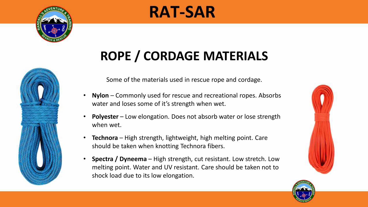
ROPE / CORDAGE MATERIALS
• Nylon – Commonly used for rescue and recreational ropes. Absorbs water and loses some of it’s strength when wet.
• Polyester – Low elongation. Does not absorb water or lose strength when wet.
• Technora – High strength, lightweight, high melting point. Care should be taken when knotting Technora fibers.
• Spectra / Dyneema – High strength, cut resistant. Low stretch. Low melting point. Water and UV resistant. Care should be taken not to shock load due to its low elongation.
Some of the materials used in rescue rope and cordage.

ROPE CARE
• Avoid shock loading.
• Avoid excessive abrading of the rope.
• Do not use Chlorine bleach or chemicals for cleaning.
• Inspect rope before and after each use.
• Wash rope after use in dirty environments.
• Do not dry in a clothes dryer.
• Store in a rope bag.
• Avoid prolonged exposure to UV rays.
• Always cut out any bad section.
• Protect the rope from all sharp edges.
• Never buy a used rope for lifeline purposes.
• Stepping on the rope (discuss the myth)

WHEN TO RETIRE A ROPE / WEBBING
• If the rope has taken a hard fall (shock loaded) or used for some nonstandard use (such as towing a car), it should be retired.
• Before and after every use, each rope should be inspected along its entire length. Feel the rope for changes in diameter (swelling or shrinking), cuts or extreme abrasion. Any bad spots should be cut out and discarded.
Is this rope still safe?

HARDWARE
• Carabiners• Descenders / Lowering Devices• Ascenders / Rope Grabs• Pulleys • Rigging Plates

CARABINER TYPES
Per NFPA, Technical use carabiners are rated at no less than 27kN on the major axis and 7 kN on the minor axis. General use carabiners are rated at 40kN on the major axis and 11 kN on the minor axis.
For wilderness operations, carabiners with at least a 22 kN major axis and 7 kN minor axis rating are acceptable.D HMS Oval
Preferred
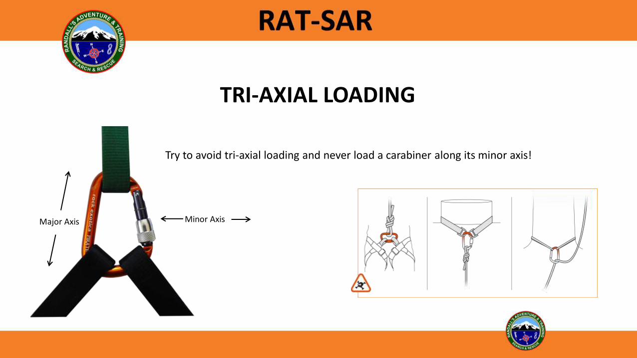
TRI-AXIAL LOADING
Major Axis Minor Axis
Try to avoid tri-axial loading and never load a carabiner along its minor axis!
CARABINER ORIENTATION• When horizontal, it is typically better to have the gate up so the
gate can be seen, however situations may dictate otherwise.
• When vertical, most practitioners suggest gate down (discuss the myth of vibration causing the gate to screw down).
• Front tensioning the system may help to keep horizontal anchor carabiners loaded properly against the spine.
SCREW GATES VS. AUTO-LOCKERS• Anyone can operate a screw gate without much thought.• Screw gates can jam easier than auto-lockers from being loaded.• Screw gates seem to operate better in muddy or sandy conditions.
Discuss techniques for un-jamming a carabiner.

DESCENDERS / LOWERING DEVICES
• There are numerous descending / lowering devices on the market, including Figure 8 variations, racks, shunts, ATCs, Grigris, IDs, MPDs, etc.
• Devices should match the rope size and application they are being used for.
• Various devices are shown in this presentation for knowledge purposes but rarely used in lightweight rescue systems.
NFPA 1983 (2012) requires the following for descent control devices:
• Technical Use: MBS not less than 13.5 kN (3,034 lbf)
• General Use: MBS not less than 22 kN (4,946 lbf)

BRAKE BAR RACK
• Doesn’t twist the rope.
• Variable friction - can be adjusted in use.
• Easy to tie-off.
• Dissipates heat well.
• Can be used with a wide range of rope diameters.
• Excellent for long descents.
• Bulky and heavy compared to some descent devices.

PETZL RIG / ID / GRIGRI STYLE DEVICES
• Rope size specific.
• Auto-stop (good for work positioning).
• Some models feature anti-panic function.
• May be too bulky and heavy for lightweight operations.
• Do not work well on icy or muddy ropes.

MAESTROS / CLUTCHES / MPDs
• Heavy and bulky.• Expensive.• Rope Size Specific.• Auto-stop.• Excellent for raising and lowering systems
when changeovers may be required due to the one-way pulley.

FIGURE 8 STYLE DESCENDERS
• Lightweight, compact.
• Easy to rig.
• Can be difficult to tie-off.
• Twist the rope.
• Can be used with a variety of rope diameters.
• Most manufacturers recommend a maximum lower or descent of 100’ due to heat buildup and rope twist.
• Figure 8 devices are good to have for multi-agency rescues when 13mm ropes may be pre-deployed.

ITALIAN HITCH (MUNTER)
• Requires HMS style or pear shaped carabiner.
• Easy to tie.
• Can be used for lowers or descents.
• Not rope size specific.
• Twists the rope.
• Will wear aluminum carabiners with a lot of use.
A “must know” hitch for lightweight rescue technicians.

HYBRID DEVICES (SCARAB)
• Adjustable friction.
• Can attach rope without unclipping from anchor.
• Manufacturer claims it will not twist the rope.
• Easy lock-off.
• Can be used with dual strands of rope.
• Can be used with a wide range of rope diameters (depending on model).

TUBULAR BELAY DEVICES
• Lightweight and extremely compact.
• Can be used for descents or lowers.
• Doesn’t twist the rope.
• Auto-lock in Guide Mode.
• Can be used with dual strands of rope.
• Can be used with a wide range of rope diameters (not 13mm).

FRICTION
Different devices will have different frictions and holding capacities based on the rope, technique used, environment, etc.
Emp
iric
al T
esti
ng

FRICTION (CAPSTAN EQUATION)
The diameter of the capstan or the diameter of the rope does not matter in determining holding force. Coefficient of friction between the rope and the surface it is touching, and the degree of contact determines the holding force.
• Convert degrees of surface contact to radian
• 360 degrees = 6.28319 Radians, equivalent to 2 x π
• Coefficient of friction x radian = FACTOR
• e constant exponential by FACTOR above
• Result gives ratio of load to 1
Radians = degree of contact divided by 180 x 3.1416
How It’s calculated:

ASCENDERS & ROPE GRABS
NFPA 1983 (2012) requires the following for rope grab and ascending devices:
• Technical Use: No permanent damage to device or rope at 5 kN (1,124 lbf)
• General Use: No permanent damage to device or rope at 11 kN (2,500 lbf)

AUXILIARY EQUIPMENT
NFPA 1983 (2012) requires the following for auxiliary equipment:
• Technical Use: MBS of not less than 22 kN (4,946 lbf)
• General Use: MBS of not less than 36 kN (8,093 lbf)

PROGRESS CAPTURE DEVICESDiscuss Advantages / Disadvantages

KNOTS
The weakest part of a rope under a load is the knot. Always properly dress and set every knot in the system. An un-dressed knot can reduce the strength of the knot up to 50%.
There are numerous knots used in rescue operations. For the purpose of this course we are concentrating on a few basic knots and will cover more advanced knot application in the field training exercises.

DEFINITIONS
Hitch – A group of ties that wrap or attach to other objects or ropes.Bend – A tie that brings together two rope ends.Bight – A doubled section of rope that does not cross itself.Loop –A turn of the rope that crosses itself.
Dressed – A tie with all components properly aligned.Setting – Tightening all parts of a tie.
Working End – End of the rope used to fasten to an anchorStanding End – All of the rope not fastened at the rigging point.Running End – End of the rope that is not rigged.
.

BIGHT SIZE
Try to make the bight only as large as needed to attach to the hardware. This helps to keep the bight in the spine of the carabiner and avoids cross loading.

FIGURE 8
The Figure 8 family of knots are the most commonly used inrope work due to their strength and ability to easily untie.
Photo courtesy www.animatedknots.com

FIGURE 8 FOLLOW-THROUGH
For tying a single rope around an anchor or object.
Photo courtesy www.animatedknots.com
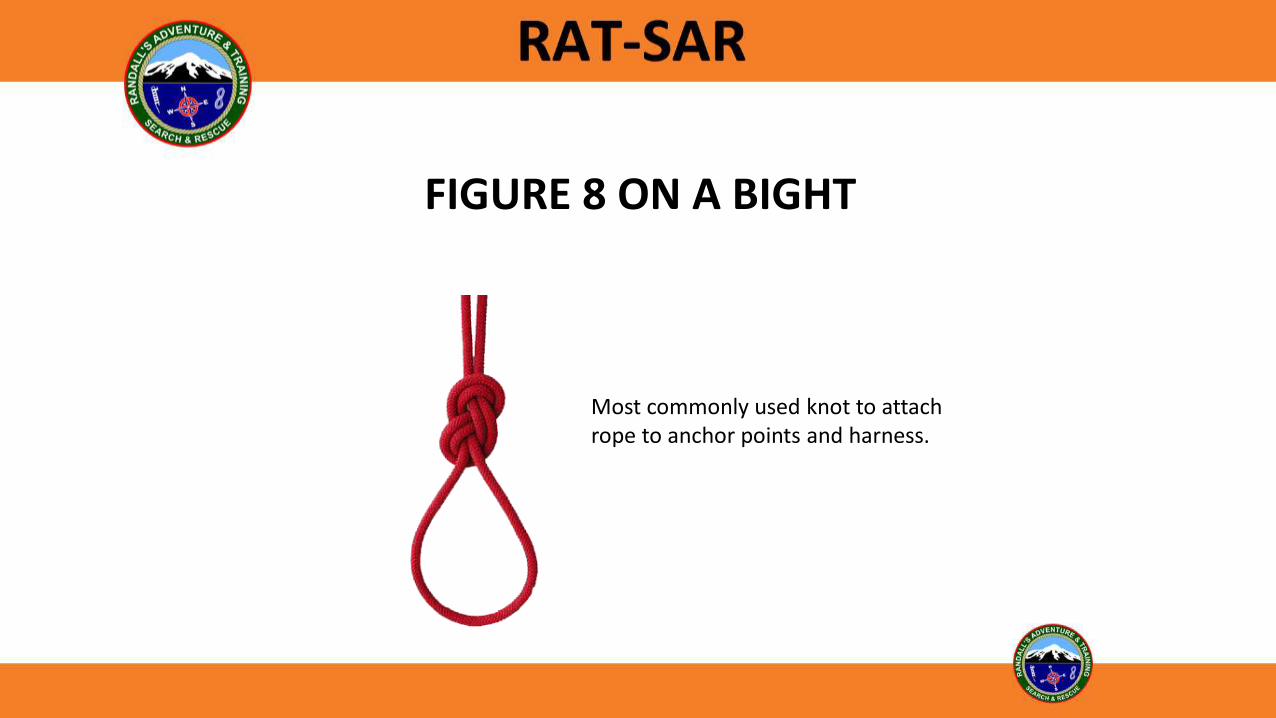
FIGURE 8 ON A BIGHT
Most commonly used knot to attachrope to anchor points and harness.
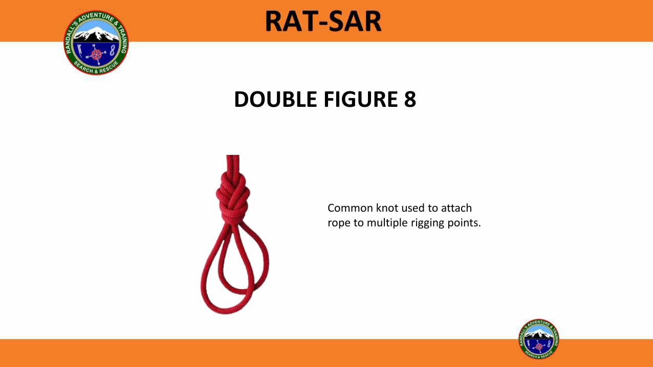
DOUBLE FIGURE 8
Common knot used to attach rope to multiple rigging points.

FIGURE 8 BEND
For tying two ends of a rope together.
Photo courtesy www.animatedknots.com

WATER KNOT
Preferred knot for tying two ends of webbing.
Photo courtesy www.animatedknots.com
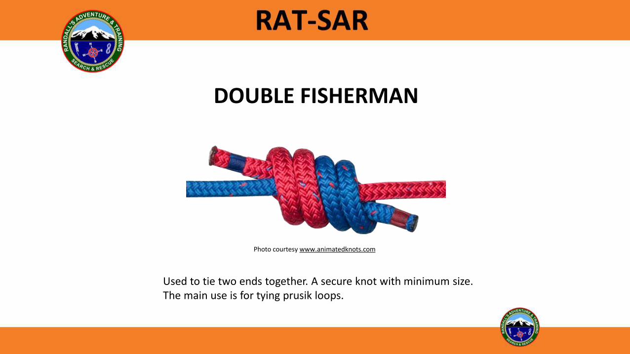
DOUBLE FISHERMAN
Used to tie two ends together. A secure knot with minimum size.The main use is for tying prusik loops.
Photo courtesy www.animatedknots.com
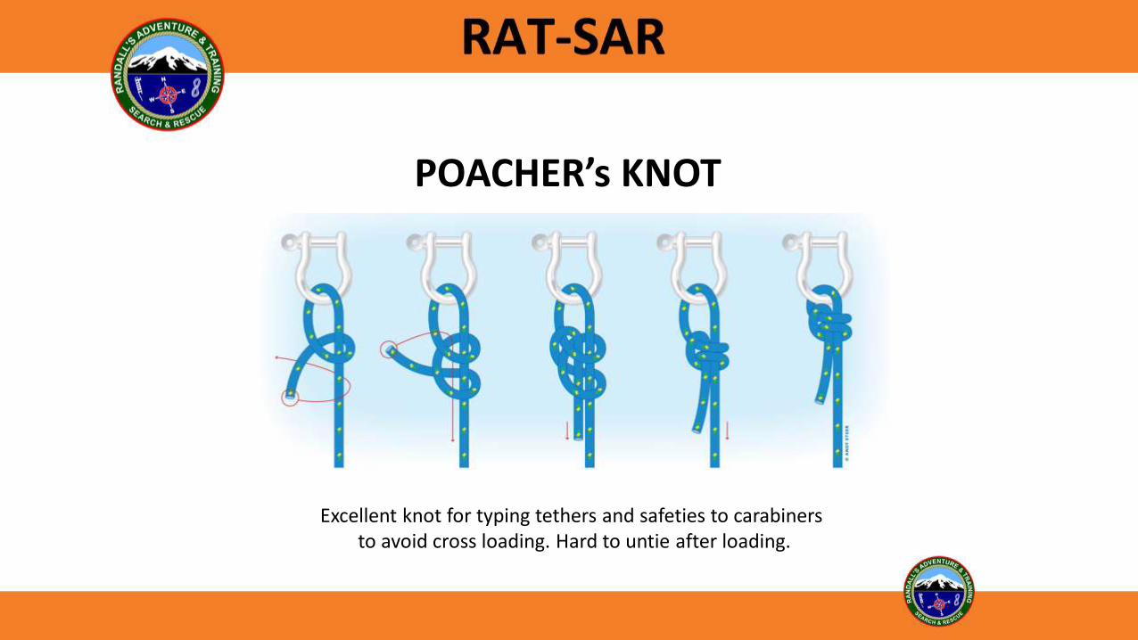
POACHER’s KNOT
Excellent knot for typing tethers and safeties to carabiners to avoid cross loading. Hard to untie after loading.

PRUSIK HITCH
A friction knot used as a rope grab.
Photo courtesy www.animatedknots.com

VALDOTAIN TRESSE (VT HITCH)
A friction knot used as a rope grab. Releasable when loaded.

CLOVE HITCH

ALPINE BUTTERFLY
Used as a mid-line knot.
Photo courtesy www.animatedknots.com

BOWLINE, SNAP BOWLINE & INTERLOCKING BOWLINE
The Bowline is an excellent all-purpose knot for rigging and anchoring as long as it has a safety or Yosemite finish. The Interlocking Bowline if often used to adjoin both ropes on a dual-rope system. A Snap Bowline is an expedient knot for tying anchors or around objects.
Bowline

RADIUM RELEASE HITCH
Used as a load releasing hitch (LRH) for rescue hauls and lowers.

TENSIONLESS HITCH(High-Strength Tie Off)
With the right anchor point, the Tensionless Hitch allows the rope to be tied off without sacrificing rope strength, unlike a knot.

KNOT BREAKING STRENGTH
Figure 8 On A Bight 20%Figure 8 Bend 19%Double Figure 8 18% Bowline 33%Double Fisherman 21%
Percentage of RopeStrength Lost*
*Test results printed in the CMC Rope Rescue Manual
Best assumption is 50% strength reduction

ANCHORS

ANCHORS
SERENE
SolidEqualizedRedundantEfficientNo Extension

Common Anchors
• Basket Hitches
• Compound
• Load Sharing
• Load Distributing
• Wrap 3, Pull 2
• Pickets
• Tensionless Hitches
• Rock Pro
• Bolts
• Deadman
• Meat Anchors
• Single Rope

ANCHOR SOFTWARE
• Webbing• Rope• Cord• Dyneema Slings
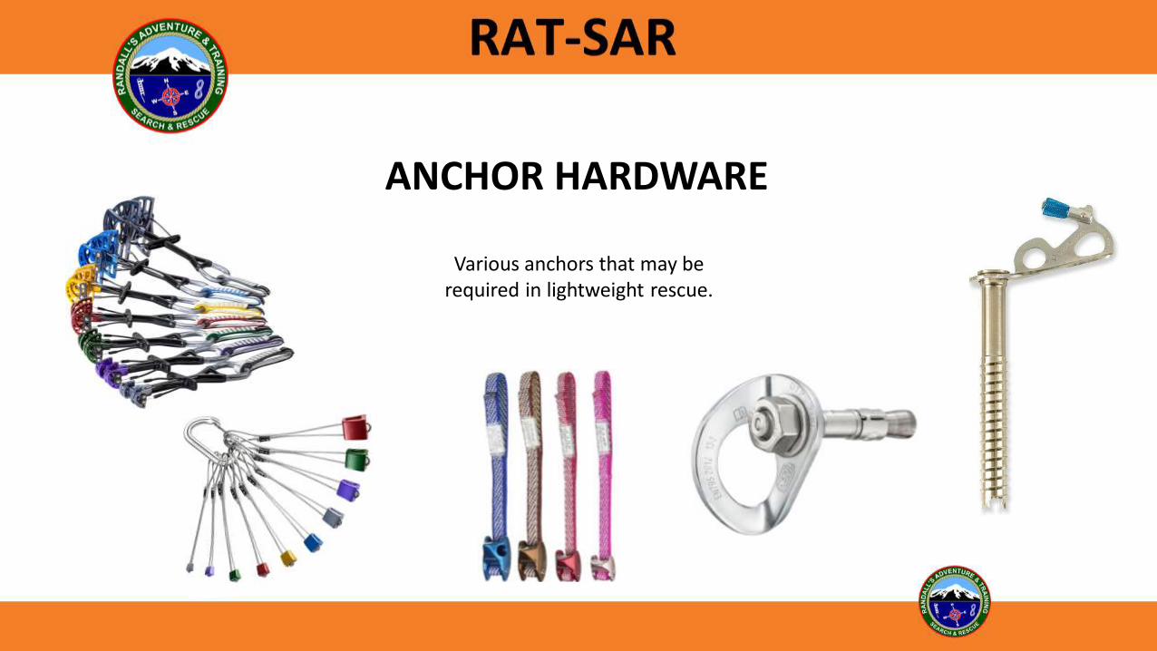
ANCHOR HARDWARE
Various anchors that may be required in lightweight rescue.

TENSIONLESS HITCH(High-Strength Tie Off)
With the right anchor point, the Tensionless Hitch allows the rope to be tied off without sacrificing rope strength, unlike a knot.

FIGURE 8 FOLLOW-THROUGH
Photo courtesy www.animatedknots.com

SIMPLE ANCHORS
Wrap 3, Pull 2 Basket HitchPotential tri-axial loading issues

WRAP 3, PULL 2
• Extremely strong anchor.• Easy to untie when knot is
placed against the anchor.

3-BIGHT (BASKET HITCH)
• Simple, quick, and can be pre-made using webbing or rope. Premade 22 kN Dyneema slings make for a quick, strong anchor.
• Be aware of triaxial loading. Use an extra carabiner if needed. Also be aware of angle.
• Caution should be used when using on short anchors such as short tree stumps since movement in the system could cause the webbing to creep upwards.

COMPOUND ANCHORSSelf-Equalizing
We do NOT suggest using self-equalizing anchors due to anchor extension and shock loading if one side fails. It is better to tie a master point instead of the anchor being self-equalizing.

LOAD SHARING ANCHORSMaster Point
• Very little anchor extension or shock loading if one side fails.
• Can be hard to untie master point (use a stone knot or carabiner in the master point to alleviate this).
• Can be tied around numerous anchor points.

MULTI-POINT ANCHORSMaster Point
• Can be made from a single piece of cord or multiple cords.
• Master point should be focused in the direction of the fall line.

ANGLE / LOAD RELATIONSHIP
With 1000 Lb. load:
1932 Lbs. each leg at 150 degrees.1000 Lbs. each leg at 120 degrees.577 Lbs. each leg at 60 degrees.517 Lbs. each leg at 30 degrees.

PRE-TENSIONED BACK-TIES
Back-ties can be tensioned by a simple inline 3:1 system using carabiners, a trucker’s hitch or a transport hitch (voodoo hitch).

ANCHORS WITH DIRECTION CHANGE
If you need need a direction change in your mainline to clear an obstruction, or to make the rappel or raise more accessible, rig the direction change the same way you would rig a main anchor. It is important to remember the anchor load relationship and the increased stresses that vectors may apply to the anchor.
100 Pound Load:
0 degrees: 200 Lbs.30 degrees: 193 Lbs.60 degrees: 173 Lbs.90 degrees: 141 Lbs.120 degrees: 100 Lbs.150 degrees: 52 Lbs.

THIS PAGE INTENTIONALLY LEFT BLANK

© Copyright 2020 RAT-SAR
WILDERNESS ROPE RESCUE OPERATIONS
Descending, Ascending, Belays, Pickoffs

SINGLE ROPE TECHNIQUE
The ability of a rescuer to descend and climb under their own power is crucial in lightweight rescue. Advantages include:
• Less force on a rescue system.• Quicker access to a search area or patient.• Less resources required to effect a rescue.• Lighter equipment / gear can be used.• More independence of movement for a
rescuer while tending the rescue load.

RAPPELLING

DESCENT CONTROL DEVICESDiscussion

CARRYING ROPE / CORDAGE
• Best methods of carrying a rope in the wilderness.
• How to coil a rope.
• How to efficiently stuff a rope bag.
• How to tie and stow cordage, slings, and prusiks.

ROPE DEPLOYMENT
• Rig your anchor and then attach rope.
• Attach yourself to the rope with a prusik hitch (or other rope grab) from your harness to the rope.
• Attach your descending device.
• Verify your belays.
• Deploy the rope over the edge.
• If you are unsure if the rope reaches the bottom, tie a stop knot in the running end of the rope so you don’t accidentally rappel off the end.
• Always carry self-rescue prusiks when rappelling or climbing.

SAFETY CHECKOFF BEFORE RAPPEL
• Gloves and helmet on.
• Verify your anchor is properly rigged.
• Verify your rope is secured to the anchor.
• Verify your harness is secure and properly fastened.
• Verify your belay (self-belay or otherwise).
• Verify the rope is properly rigged into your descender.
• Verify that all carabiners are locked.

AUDIBLE COMMANDS
• Rappeler shouts “On belay” when he/she attaches to the lifeline
• Belayer responds “Belay on”
• Rappeler shouts “Rappelling” as he/she moves to the edge
• Belayer responds “Rappel on”
• Rappeler shouts “Off rappel” once he/she detaches from the rope
• Anyone who sees any object fall from the top shouts “Rock!”

WORKING THE EDGE
Going over the edge is the most difficult part of rappelling. The lower your anchor point is in relation to your descender, the more difficult it will be.
On narrow overhangs (as shown in the photo on the right), you may have to roll off the edge. Make sure your descender is clear of the edge and you are holding brake tension before attempting this maneuver.

EDGE PROTECTION
• All places where a rope or webbing touches a sharp edge should be protected with rope pads, clothes, canvas tarps, or other materials.
• This is especially applicable when ascending a rope due to the up and down sawing action caused by climber’s movement up the rope.
• If possible use a redirect to establish a high anchor to alleviate rope rub on the edge.
• Protect any software-on-software point that has a moving component.

GUIDED RAPPELS
Useful to clear your team from obstructions or dangerous areas at the base of the fall line.
Discussion

BUDDY RAPPELS
• Useful to lower a rescuer or subject that may not be able to lower themselves.
• Tether between rescuer and patient to create a closed loop system.
• Load on each side of the rope is equal to half the combined weight of the rescuer and patient.
• Due to COD, the rope is only loaded at single-person loads.
Discussion

TAKE-DOWN RAPPELSCleaning Routes
Technical search and rescue may require the rescuer to clean the route and carry their rope as they traverse down an area. Examples of this include waterfall searches and canyon searches. Some of the ways to clean a route are:
• Twin line rappels
• ”Biner” Blocks, Knot Blocks on single rope
• Pull Cords and EDKs

SELF BELAYS / AUTOBLOCKS
VT Hitches should be used instead of 3-wrap prusiks when using hitches for self-belays above your descender.
Self-belays and autoblocks are not a backup for a mainline failure or operator error. Independent belays are always the safest belays.

BOTTOM BELAY (SRT)(AKA Fireman Belay)
This belay system is not a backup for a mainline failure.

INDEPENDENT BELAYS
Independent belays use a second rope to catch the rescuer should the mainline fail or the rescuer make a mistake. They can be configured to belay from the topside anchor or from the bottom by running the belay line through a redirect at the top.
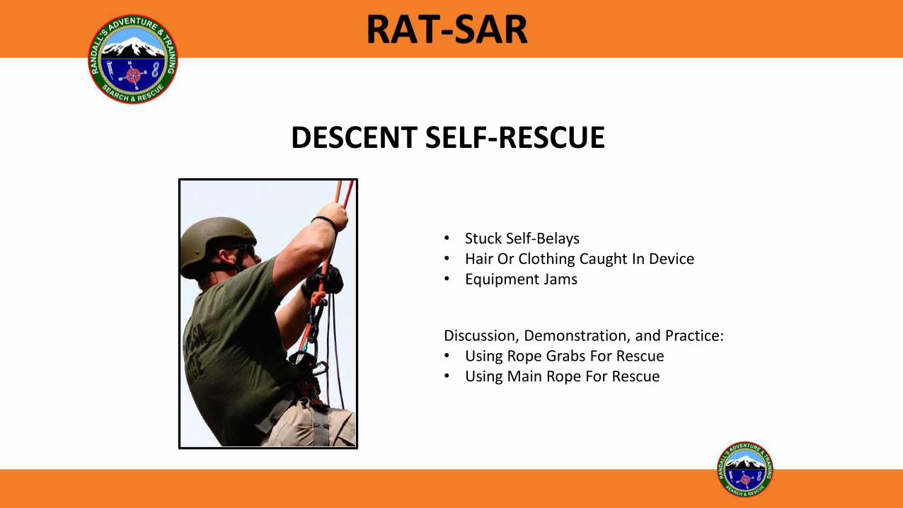
• Stuck Self-Belays • Hair Or Clothing Caught In Device• Equipment Jams
Discussion, Demonstration, and Practice:• Using Rope Grabs For Rescue• Using Main Rope For Rescue
DESCENT SELF-RESCUE
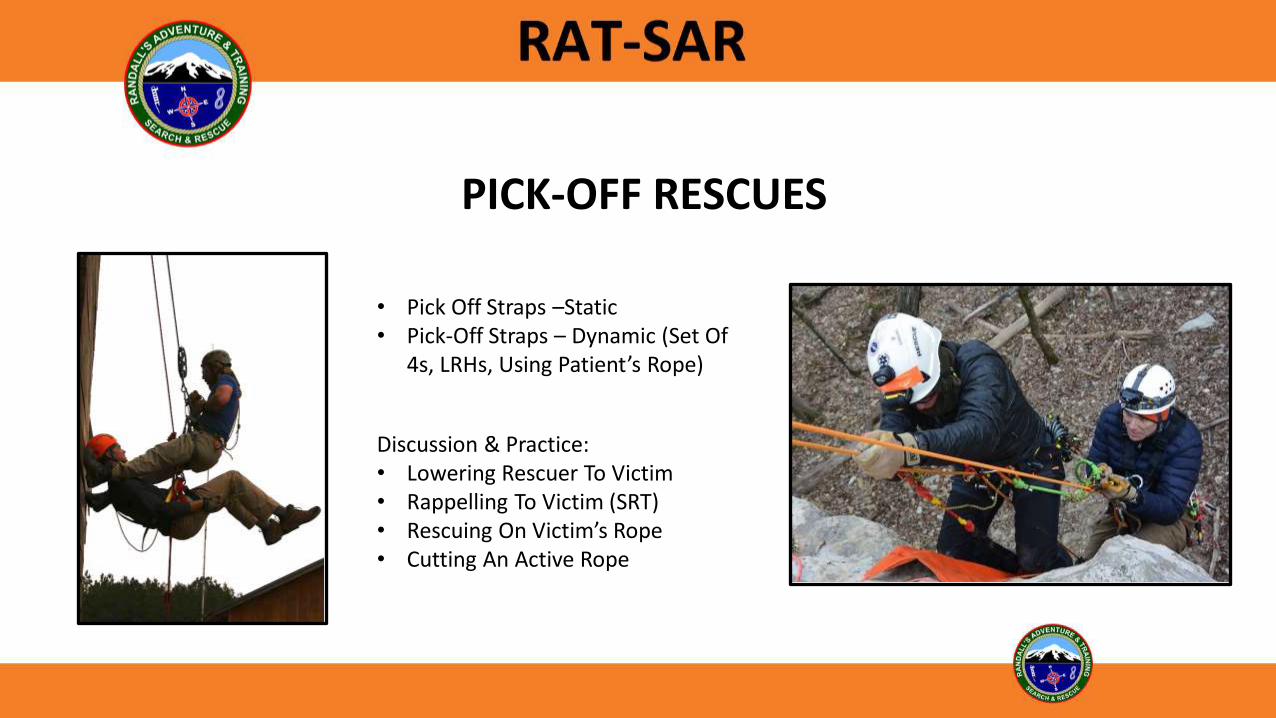
PICK-OFF RESCUES
• Pick Off Straps –Static• Pick-Off Straps – Dynamic (Set Of
4s, LRHs, Using Patient’s Rope)
Discussion & Practice:• Lowering Rescuer To Victim• Rappelling To Victim (SRT)• Rescuing On Victim’s Rope• Cutting An Active Rope

ASCENDING WITH MECHANICAL ASCENDERS
In lightweight rescue, it is essential that wilderness rescue technicians have the ability to efficiently climb a rope.

ASCENDING WITH MECHANICAL ASCENDERS
Frogging Texas Rope Walker
SYSTEMS

FROG SYSTEM
QAS (Quick Attach Safety) not shown.
The Frog System is a preferred system in lightweight rescue.

CHANGEOVER FROM RAPPEL TO ASCEND
1. Hard lock descender (or allow self-belay prusik to take the load).
2. Attach prusik cord or capture device just above descender and attach to harness (If you are already using a self-belay prusik cord attached above the descender then you can use this).
3. Attach ascender with foot loop to the rope.
4. Unlock descender and slowly allow the prusik (or progress capture) to take the load (No need to do this if you have already transferred load to the self-belay prusik).
5. Remove descender from the system and secure.
6. Push up with your leg in the foot loop. This will raise you high enough to take the load off of the harness prusik.
7. Push harness prusik (or other progress capture) up the rope and transfer your weight to it.
8. Repeat pushing up with your leg and transferring weight until you reach the top.

CHANGEOVER FROM ASCEND TO RAPPEL
1. Attach QAS and allow foot loop safety or QAS to hold your weight.
2. Attach descender to the rope below the QAS or safety. Remove as much rope slack as possible.
3. Move the ascender with the foot loop up as high as possible, then push up with your leg, removing slack in the descender as you go up.
4. Once all slack is removed from descender, transfer the load to the descender by lowering yourself with your pushing leg.
5. Lock off the descender.
6. Remove ascender with foot loop and secure.
7. Remove harness prusik (or leave on as a self-belay)
8. Slowly unlock descender making sure you maintain rope friction with your brake hand.
9. Rappel normally.

ASCENDING WITH PRUSIKS
• Ascending with prusiks is the same principle as using mechanical ascenders. Be sure to carry both the harness and foot prusiks with you when you rappel, and make sure their length is adjusted to work as ascenders.
• It is always best to design and test your prusiks and ascender cords on the ground first. Test them by climbing the rope from ground up before you need them on a rappel.

ETRIERS
Etriers are short manufactured or field fabricated “ladders” made from webbing. They are extremely handy for negotiating over the edge when ascending a rope with prusiks or mechanical ascenders. When attached to an ascender they can be used for ascending a rope.

THIS PAGE INTENTIONALLY LEFT BLANK

© Copyright 2020 RAT-SAR
WILDERNESS ROPE RESCUE OPERATIONS
Mechanical Advantage, Raises, Lowers, Changeovers, Knot Passes,
Litters / Patient Packaging, High Directionals
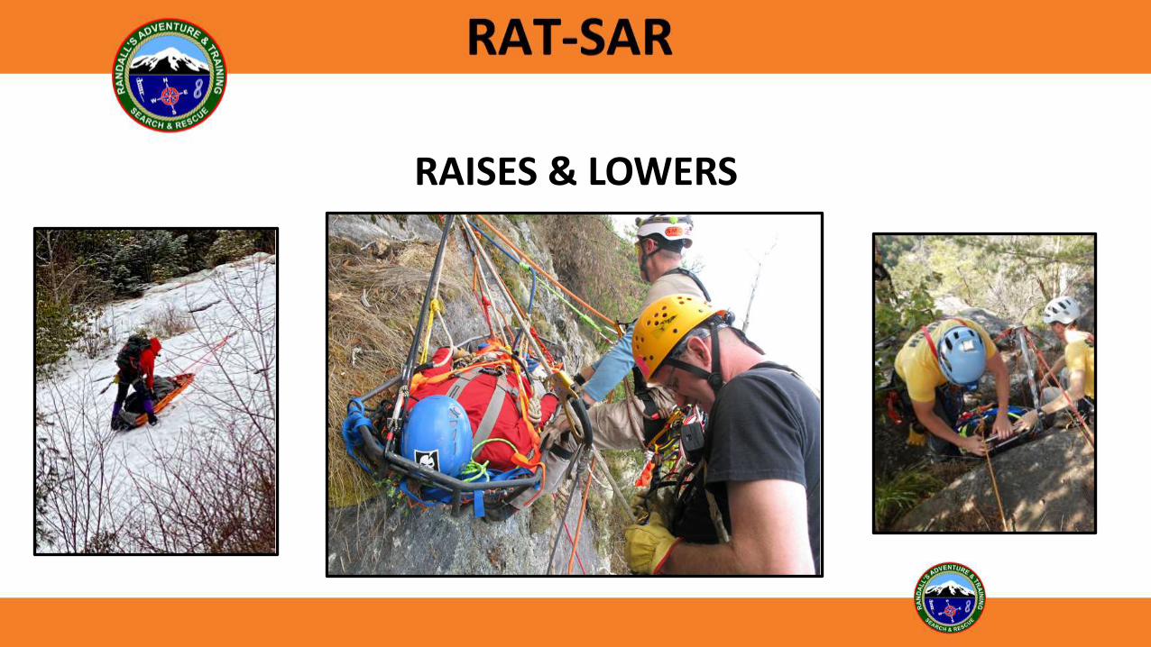
RAISES & LOWERS

RPM SYSTEM
Rack (lowering Device)Pulley (COD for Raising Mechanical Advantage)Mariners (Load Release Hitch)
The RPM system is still in use among many rescue teams. This system uses a main line for raising and lowering and a separate belay line for safety.
(Rack, Pulley, Mariner - Also Known as a Main and Belay System)

LOAD RELEASE HITCHES
• Mariners Hitch
• Radium Release Hitch
• Piggyback Rigs (”set of 4’s” can also be used to transfer loads and do pick-off rescues)
A load release hitch allows the load to be transferred from one rope to another, or transfer load during a changeover from one direction to another. They can also be used to do pick-off rescues and knot passes.
Quickly built in the field from 8mm Body Cord

DUAL TENSION SYSTEMS (RAISING / LOWERING)
• Reduces shock load potential due to tension being shared by both lines at all times.
• Both ropes serve as mainlines and backup lines at the same time.
• Rigging is typically the same for both lines, thus less complexity in equipment and operating techniques.
• Since both ropes are active, each line operator is more attentive to the operation.
Preferred Systems For Lightweight Rescue

SYSTEMS
Load
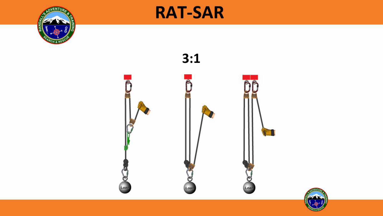
Dual Tension 3:1 SystemRPM 3:1 System

PRINCIPLES OF MECHANICAL ADVANTAGE (MA)
The Basics:
• End of rope starts at load = Odd ratio of MA
• End of rope starts at anchor = Even ratio of MA
• Moving pulley: Creates mechanical advantage
• Static pulley: COD (Change of Direction – does not create mechanical advantage)
1:1 1:1 2:1

PRINCIPLES OF MECHANICAL ADVANTAGE (MA)
To raise a 200 Lb. load through a 1:1 COD requires 200 Lbs. + of force on the pull side of the rope. This creates 400 pounds of force on the anchor holding the COD pulley.
Load Weight: 200 Lbs.
200 Lbs. 200 Lbs.
400 Lbs. on anchor

PRINCIPLES OF MECHANICAL ADVANTAGE (MA)
Compound Simple Complex
Compound: One system pulling another system.
Simple: A single rope is looped through a set of pulleys, and all of the pulleys move at the same speed.
Complex: Typically consists of two or more pulleys traveling in the opposite direction at potentially different rates.

THE “T” METHOD
1T
2T
1T
3T
Start at the hand with one tension of force. Every place it makes a bend around a pulley it becomes two tensions of force. Forces of moving pulleys and rope tension are added together at the load.
Ideal MA: The calculated MA without accounting for losses in the system such as friction.
Actual MA: The actual MA produced in a system.
The T-System always assumes that the pulleys are frictionless and that the ropes make 180-degree turns around the pulleys.
Adding the Tensions

1:1 / 2:1
Non-moving COD adds no mechanical advantage for
moving the load. It creates additional force on the anchor.
Moving pulley creates mechanical advantage
3:1
4:1

5:1

6:1

7:1
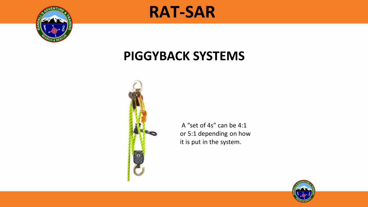
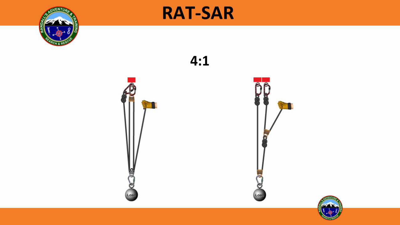
PIGGYBACK SYSTEMS
A “set of 4s” can be 4:1 or 5:1 depending on how it is put in the system.

INSIDE 9s
5:14:1

Discussion:
• Using carabiners to build mechanical advantage.
• Counterbalance systems.
• Breaking into an active rope.
IMPROVISED SYSTEMS / TECHNIQUES

LOWERING SYSTEMS

CHANGEOVER LOWER TO RAISE
1. Lock-off descender.2. Lock off belay rope.3. Insert LRH or long prusiks into system between the
descender and the load.4. Unlock descender and lower until load is transferred
to LRH or long prusiks or belay line has the load.5. Insert haul pulleys and progress capture prusiks.6. Unlock belay and prepare to belay the raising
process. 7. Proceed with raising and remove LRH or long prusiks.
RPM System
The integrity of both lines must remain intact throughout the changeover process!

CHANGEOVER LOWER TO RAISE
1. Lock-off both descenders. 2. Changeover one side at a time.3. Insert LRH or long prusiks into one side of the system
between the descender and the load.4. Unlock descender and lower until load is transferred to
LRH or long prusiks or second line has the load.5. Insert haul pulleys and progress capture prusiks.6. Set the progress capture prusiks and remove LRH or long
prusiks.7. Changeover the other side by repeating the steps above.
Dual Tension System
The integrity of both lines must remain intact throughout the changeover process!

CHANGEOVER RAISE TO LOWER
1. Insert LRH between progress capture prusiks and load.2. Raise the system slightly to release progress capture prusiks and allow the
LRH prusiks to hold the load.3. Remove haul pulleys.4. Insert main rope into descender and remove as much slack as possible.5. Attach the descender to the anchor.6. Lock off the rope in the descender.7. Slowly release LRH until load is transferred to descender.8. Unlock rope from descender and proceed with lowering.
Note: there are alternate methods that can be used to do changeovers. The most important aspect to any changeover (on any system) is to maintain the integrity of both lines throughout the process.

KNOT PASS LOWERING
1. Stop lowering before knot reaches descender (do not let the knot jam into the descender – leave plenty of space).
2. Attach LRH (Radium Release Hitch) and prusiks below the descender (load side).
3. Lower with descender until load is transferred to LRH.
4. Remove descender and reattach beyond the knot.
5. Lock off descender.
6. Lower the load with the LRH until load is transferred back to descender.
7. Remove the LRH and prusik.
8. Continue the lowering process with descender.

KNOT PASS RAISING
1. Pass the haul prusik past the knot during a haul rest.
2. Continue to raise until the knot runs into the ratchet prusik and primary haul pulley.
3. Stop the raise and attach a new pulley and ratchet prusiks between the knot and the load.
4. Continue to raise. This will create a “dead leg” and temporarily reduce the value of your mechanical advantage. Once enough slack comes into this dead leg, attach the new pulley and prusiks into the main anchor.
5. Pull all slack through the new prusiks and allow the load to be transferred to these prusiks.
6. Remove the original primary haul pulley and ratchet prusiks.
7. Continue with the raising operation.
Slamma Jamma Technique on a 3:1 System

KNOT PASS RAISING
1. Pass the haul prusik past the knot during a haul rest.
2. Continue to raise until the knot reaches the ratchet prusiks.
3. Attach an LRH and prusiks well below the knot leaving enough distance to accommodate a pulley and ratchet prusiks.
4. Transfer the load to the LRH. Ratchet prusiks will have to be minded during this phase to keep them from grabbing.
5. Reattach the original pulley and ratchet prusiks below the knot (between the knot and the load).
6. Haul team can now begin to raise.
7. Once slack comes in the LRH, it can be removed.
8. Pass the knot past the second pulley (haul pulley) during a reset.
Alternate Method

OPERATION COMMANDS
“Haulers Ready” - Team should be ready to haul.“Attendant Ready” - Attendant ready to be raised or climb.“Up – Haul Slow” - Team begins hauling.“Set” - Team stops and sets ratchet.“Reset” - Team resets system to prepare to haul again.“Stop” - All movement stop and tension is held.“Down” - Lower the load.
Single person should be giving commands

BELAYINGA belay is a secondary process or piece of equipment that protects the load from falling should the primary process or piece of equipment fail. A “belay” line is not used or required in a dual tension system, since both lines are either lowering or raising at the same time.

INDEPENDENT BELAYS
Independent belays use a second rope to catch the load should the mainline fail. They can be configured to belay from the topside anchor or from the bottom by running the belay line through a redirect at the top.
Used in a Main / Belay type system.

TANDEM PRUSIK BELAYS
Prusiks should be about 25% smaller than the rope they are attached to.
On tandem prusik systems the short prusik always attaches between the long prusik and the anchor.
For Independent Belay Lines
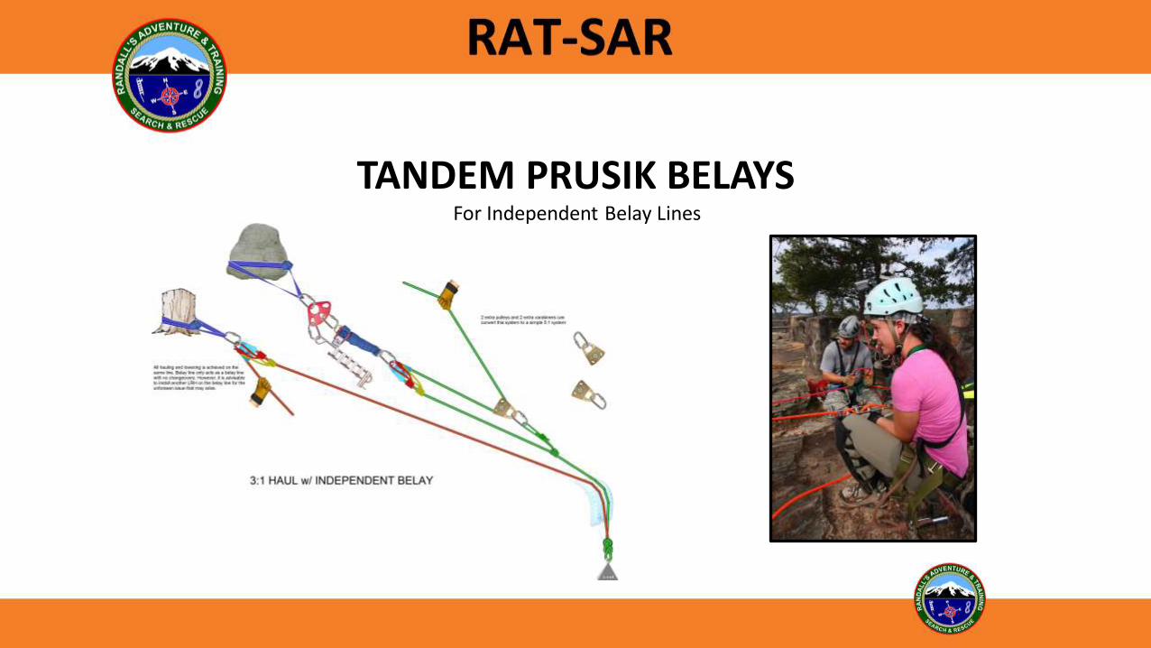
TANDEM PRUSIK BELAYSFor Independent Belay Lines

HIGH DIRECTIONALS
• Purpose
• Anchor / Re-Direct
• Guy Lines
• Resultant Angle and Forces
• Natural and Improvised
• Gin Poles, A-Frames, Tripods

LIGHTWEIGHT GIN POLES• Best practice is to have the back tie in line with the load lines.
• Side guy lines have to be far enough forward to keep the gin pole from flipping backwards.
• Resultant force should bisect the included angle of the main line, or be slightly forward.
• Included angle of 120 degrees on main line compresses the gin pole with the same force that is on the line. Less angle increases compression force, more angle lessens compression force.
• Front ties at the base of gin pole may be necessary.
• Do not exert any side or lateral force on the gin pole.
• Gin poles are stronger when used as a redirect instead of as a main anchor.

FLOATING DIRECTIONALS
• Dynamic - can be adjusted while loaded.
• Less friction than over-the-edge rescues.
• Provides working room and clearance.
• Keep in mind the angle / load relationship.

LITTER TYPES
Stokes Basket
Sked
Demonstrate pre-rig patient securing line.

PATIENT PACKAGING
• Advise patient of your rescue/evacuation plan.
• Add a tarp and blanket to floor of litter before placing patient in the basket.
• Place a harness on the patient.
• Place patient in the litter, then wrap the tarp and blanket and tuck under the patient to waterproof and insulate.
• Secure patient’s harness to the top of the litter.
• In a stokes basket, secure patient to the lowest rail on the litter which provides more security and less chance of abrasion during rescue.
• Pad the patient where webbing makes contact and pad all voids.
• Recheck patient’s circulation after packaging.
• Provide helmet and eye protection to the patient.
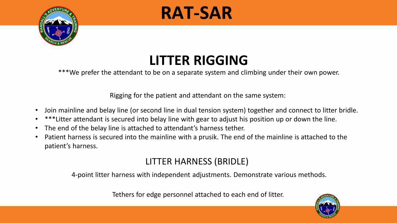
LITTER RIGGING
• Join mainline and belay line (or second line in dual tension system) together and connect to litter bridle.• ***Litter attendant is secured into belay line with gear to adjust his position up or down the line.• The end of the belay line is attached to attendant’s harness tether.• Patient harness is secured into the mainline with a prusik. The end of the mainline is attached to the
patient’s harness.
4-point litter harness with independent adjustments. Demonstrate various methods.
LITTER HARNESS (BRIDLE)
Tethers for edge personnel attached to each end of litter.
***We prefer the attendant to be on a separate system and climbing under their own power.
Rigging for the patient and attendant on the same system:
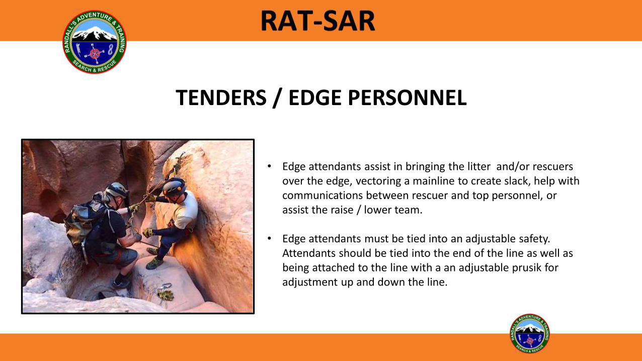
TENDERS / EDGE PERSONNEL
• Edge attendants assist in bringing the litter and/or rescuers over the edge, vectoring a mainline to create slack, help with communications between rescuer and top personnel, or assist the raise / lower team.
• Edge attendants must be tied into an adjustable safety. Attendants should be tied into the end of the line as well as being attached to the line with a an adjustable prusik for adjustment up and down the line.

0-15 degree - considered flat terrain15-29 degrees - low angle30-50 degrees - steep angleabove 50 degrees - high angle
LOW ANGLE RAISES & LOWERS
Possibly use a re-direct with rescuers walking downhill to move load uphill instead of setting up a full MA system.

FLAT to LOW TERRAIN EVACUATIONS
• Have adequate resources – minimum of 6-8 persons.
• Have a route finder to go ahead of litter team.
• Lift load with legs, not back.
• Lift and lower as a team.
• A belay may be needed depending on the terrain.
• Learn to rotate out team members while moving.

LOW ANGLE BELAYS
Depending on the terrain, a simple wrap around a tree with a single person tending is usually sufficient to provide safety to the patient and litter team on rough, uneven, sloping terrain.

HORIZONTAL SYSTEMS
Horizontal systems such as highlines are considered advanced techniques. The following slides are for awareness discussion only and not part of the skills portion of this course.

HORIZONTAL LINESAwareness Discussion Only

HIGHLINE TENSIONING RULE OF 12/18
• When applying mechanical advantage to a loaded 11mm (7/16”) rope never exceed a 12:1 MA. For example, if the MA system is a 3:1, then you should not exceed 4 people hauling on the system.
• When applying mechanical advantage to a loaded 13mm (1/2”) rope never exceed an 18:1 MA. For example, if the MA system is a 3:1, then you should not exceed 6 people hauling on the system.
Awareness Discussion Only

SKATE BLOCKS / SLOPING HIGHLINES
Excellent method to avoid danger areas or obstacles directly beneath the patient.
Awareness Discussion Only

TWO-ROPE OFFSETAwareness Discussion Only

SUGGESTED STUDY
National Park Service Technical Rescue Handbook 11th Edition
Download at: www.randallsadventure.com
andwww.ratsar.org
Minimalist Wilderness Rigging – Volume 3Pat Rhodes
ISBN-13: 978-1700165893ISBN-10: 1700165895