Wide Color Video Doorphone - SEGEDIP.com · Wide Color Video Doorphone Model No. CDV-50/50D Use and...
15
Before operating the unit, please read this manual thoroughly and retain it for future reference. Wide Color Video Doorphone Model No. CDV-50/50D Use and Care Guide
Transcript of Wide Color Video Doorphone - SEGEDIP.com · Wide Color Video Doorphone Model No. CDV-50/50D Use and...
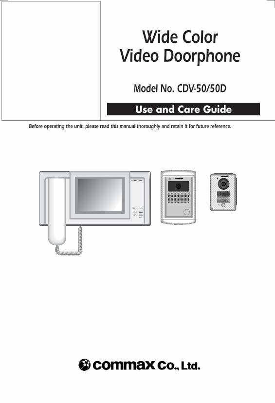
Before operating the unit, please read this manual thoroughly and retain it for future reference.
Wide Color Video Doorphone
Model No. CDV-50/50D
Use and Care Guide
‐ 2 ‐
CAUTIONRISK OF ELECTRIC SHOCK
DO NOT OPEN
CAUTION : TO REDUCE THE RISK OF ELECTRIC SHOCK, DONOT REMOVE COVER (OR BACK). NO USER-SERVICEABLEPARTS INSIDE. REFER SERVICING TO QUALIFIED SERVICEPERSONNEL.
Introduction
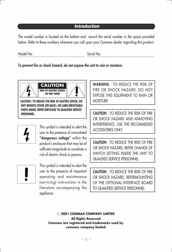
The model number is located on the bottom and record the serial number in the space providedbelow. Refer to these numbers whenever you call upon your Commax dealer regarding this product.
Model No. Serial No.
To prevent fire or shock hazard, do not expose the unit to rain or moisture.
This symbol is intended to alert theuser to the presence of uninsulated“dangerous voltage” within theproduct’s enclosure that may be ofsufficient magnitude to constitute arisk of electric shock to persons.
This symbol is intended to alert theuser to the presence of importantoperating and maintenance(servicing) instructions in theli terature accompanying theappliance.
2001 COMMAX COMPANY LIMITEDAll Rights Reserved
Commax are registered and trademarks used by commax company limited
WARNING : TO REDUCE THE RISK OFFIRE OR SHOCK HAZARD, DO NOTEXPOSE THIS EQUIPMENT TO RAIN ORMOISTURE
CAUTION : TO REDUCE THE RISK OF FIREOR SHOCK HAZARD AND ANNOYINGINTERFERENCE, USE THE RECOMMEDEDACCESSORIES ONLY
CAUTION : TO REDUCE THE RISK OF FIREOR SHOCK HAZARD, REFER CHANGE OFSWITCH SETTING INSIDE THE UNIT TOQUALFIED SERVICE PERSONNEL
CAUTION : TO REDUCE THE RISK OF FIREOR SHOCK HAZARD, REFERMOUNTINGOF THE OPTIONAL INTERFACE BOARDTO QUALIFIED SERVICE PERSONNEL

‐ 3 ‐
Important Safeguards
Read Instructions - All safety and operatinginstructions should be read before the unit isoperated.
Retain Instruction - The safety and operatinginstructions should be retained for futurereference.
Heed Warnings - All warnings on theequipment and in the operating instructionsshould be adhered to.
Follow Instruction - All operating and useinstructions should be followed.
Ventilation - Slots and openings in thecabinet are provided for ventilation and toprotect it from overheating.
Power Sources - This equipment should beoperated only from the type of power sourceindicated on the marking label.
Grounding - This product is equipped with apolarized alternating - current line plug. Thisplug wil l f i t into the power outlet onlyoneway. This is a safety feature.
Power Cord Protection - Power- supplycords should be routed so that they are notlikely to be walked on or pinched by itemsplaced upon or against them; pay particularattention to cords at plugs, conveniencereceptacles and the point where cords exitfrom the equipment.
Overloading - Do not overload power outletsand extension cords as this can result in arisk of fire or electric shock.
Damage Requiring Service - Unplug thisequipment from the power source and referservicing to qualified service personnel underthe following conditions:a. when the power supply cord or plug is
damaged;b. if liquid has been spilled or objectes have
fallen into the unit.;c. if the equipment has been exposed to rain
or water;d. if the equipment has been dropped or
otherwise damaged;e. when the equipment exhibits a distinct
change in performance - this indicates aneed for service.
Water and Moisture - Do not use thisproduct near water, for example, near abath tub, wash bowl, kitchen sink, or laundrytub, in a wet basement, or near a swimmingpool, and the like.
Accessories - Do not place this product on anunstable cart, stand, tripod, bracket, or table.The product may fall, causing serious injuryto a child or adult, and serious damage tothe appliance.
Object and Liquid Entry - Never push objectsof any kind into this product throughopenings as they may touch dangerousvoltage points or short-out parts that couldresult in a fire or electric shock. Never spillliquid of any kind on the product.
1.
2.
3.
4.
5.
6.
7.
8.
9.
10.
11.
12.
13.
Note : Do not place this product directly onwood or simulated woods surfaces as thesessurfaces are easily damaged.
‐ 4 ‐
Important Safeguards
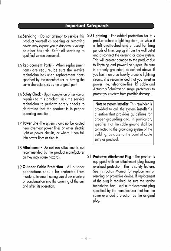
Lightning - For added protection for thisproduct before a lightning storm, or when itis left unattached and unused for longperiods of time, unplug it from the wall outletand disconnect the antenna or cable system.This will prevent damage to the product dueto lightning and power-line surges. Be sureis properly grounded, as defined above. Ifyou live in an area heavily prone to lightningstroms, it is recommended that you invest inpower-line, telephone-line, RF cable andActuator/Polarization surge protectors toprotect your system from possible damage.
Protective Attachment Plug - The product isequipped with an attachment plug havingoverload protection. This is safety feature.See Instruction Manual for replacement orresetting of protective device. If replacementof the plug is required, be sure the servicetechnician has used a replacement plugspecified by the manufacturer that has thesame overload protection as the originalplug.
14.
15
16
17
18
19
20
21
Note to system installer: This reminder isprovided to call the system installer’sattention that provides guidelines forproper grounding and, in particular,specifies that the cable ground shall beconnected to the grounding system of thebuilding, as close to the point of cableentry as practical.
Servicing - Do not attempt to service thisproduct yourself as opening or removingcovers may expose you to dangerous voltageor other hazards. Refer all servicing toqualified service personnel.
Replacement Parts - When replacementparts are require, be sure the servicetechnician has used replacement partsspecified by the manufacturer or having thesame characteristics as the original part.
Safety Check - Upon completion of service orrepairs to this product, ask the servicetechnician to perform safety checks todetermine that the product is in properoperating condition.
Power Line -The system should not be locatednear overheat power lines or other electriclight or power circuits, or where it can fallinto power lines or circuits.
Attachment - Do not use attachments notrecommended by the product manufactureras they may cause hazards.
Outdoor Cable Protection - All outdoorconnections should be protected frommoisture. Internal heating can draw moistureor condensation into the covering of the unitand affect its operation.
‐ 5 ‐
Table Contents
Before You Begin
Operation
Troubleshooting Guide
Specifications
Introduction ..............................................................................................2
Important Safeguard ..................................................................................3
Table Contents ...........................................................................................5
Preparations ..............................................................................................6
Location and function of controls (For Monitor) .............................................7
Location and function of controls (For Camera).............................................8
Operating
Operating And Function Of Control.............................................................9
1. Communication with the Doorphone Function......................................9
2. Communication with the Interphone....................................................9
How To Installation (For Monitor)...............................................................10
How To Installation (For Camera) ..............................................................11
Part List ................................................................................................12
Troubleshooting Guide .....................................................................13
Specifications ......................................................................................14
‐ 6 ‐
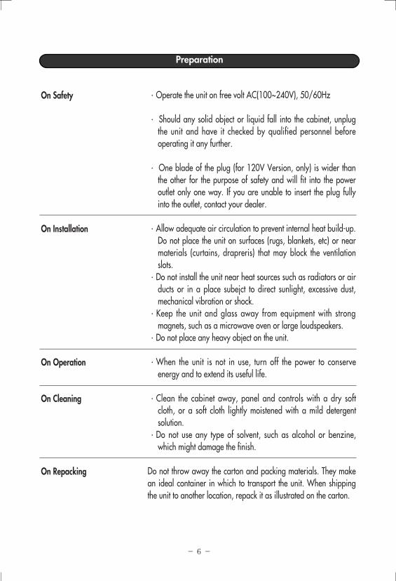
·Operate the unit on free volt AC(100~240V), 50/60Hz
· Should any solid object or liquid fall into the cabinet, unplugthe unit and have it checked by qualified personnel beforeoperating it any further.
· One blade of the plug (for 120V Version, only) is wider thanthe other for the purpose of safety and will fit into the poweroutlet only one way. If you are unable to insert the plug fullyinto the outlet, contact your dealer.
·Allow adequate air circulation to prevent internal heat build-up.Do not place the unit on surfaces (rugs, blankets, etc) or nearmaterials (curtains, drapreris) that may block the ventilationslots.
·Do not install the unit near heat sources such as radiators or airducts or in a place subejct to direct sunlight, excessive dust,mechanical vibration or shock.
·Keep the unit and glass away from equipment with strongmagnets, such as a microwave oven or large loudspeakers.
·Do not place any heavy object on the unit.
·When the unit is not in use, turn off the power to conserveenergy and to extend its useful life.
·Clean the cabinet away, panel and controls with a dry softcloth, or a soft cloth lightly moistened with a mild detergentsolution.
·Do not use any type of solvent, such as alcohol or benzine,which might damage the finish.
Do not throw away the carton and packing materials. They makean ideal container in which to transport the unit. When shippingthe unit to another location, repack it as illustrated on the carton.
On Safety
On Installation
On Operation
On Cleaning
On Repacking
Preparation
‐ 7 ‐
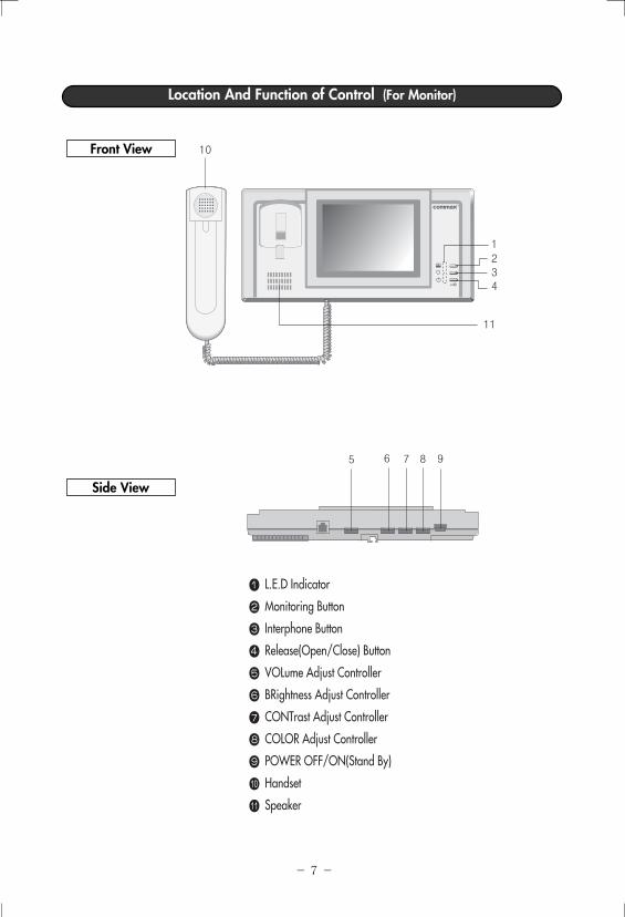
Location And Function of Control (For Monitor)
Front View
Side View
L.E.D Indicator
Monitoring Button
Interphone Button
Release(Open/Close) Button
VOLume Adjust Controller
BRightness Adjust Controller
CONTrast Adjust Controller
COLOR Adjust Controller
POWER OFF/ON(Stand By)
Handset
Speaker
21
34
11
5 6 7 8 9
10
‐ 8 ‐
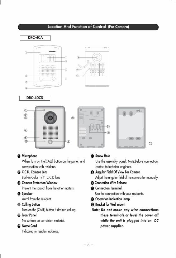
Location And Function of Control (For Camera)
MicrophoneWhen Turn on the[CALL] button on the panel, andconversation with residents.C.C.D. Camera LensBuilt-in Color 1/4”C.C.D lensCamera Protection WindowPrevent the scratch from the other matters.SpeakerAural from the resident.Calling ButtonTurn on the [CALL] button if desired calling.Front PanelNo surface on corroision material.Name CardIndicated in resident address.
Screw HoleUse the assembly panel. Note:Before connection,contact to technical engineer.Angular Field Of View For CameraAdjust the angular field of the camera for manually.Connection Wire ReleaseConnection TerminalUse the connection with your residents. Operation Indication LampBracket for Wall mount
Note: Do not make any wire connectionsthese terminals or level the cover offwhile the unit is plugged into an DCpower supplier.
DRC-4CA
DRC-40CS
①
②
③
④
⑤⑥
⑦
⑧
⑨
⑩
⑪
‐ 9 ‐
Operation
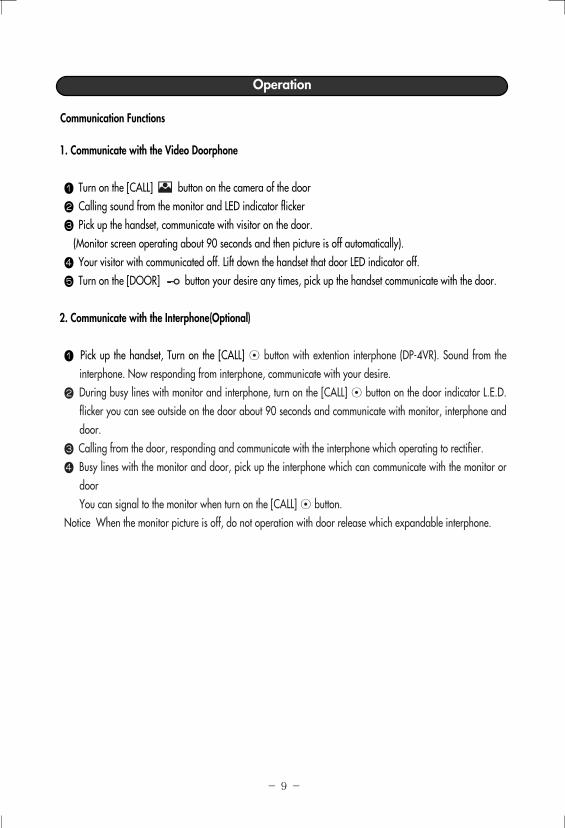
Communication Functions
1. Communicate with the Video Doorphone
Turn on the [CALL] button on the camera of the doorCalling sound from the monitor and LED indicator flickerPick up the handset, communicate with visitor on the door.
(Monitor screen operating about 90 seconds and then picture is off automatically).Your visitor with communicated off. Lift down the handset that door LED indicator off.Turn on the [DOOR] button your desire any times, pick up the handset communicate with the door.
2. Communicate with the Interphone(Optional)
Pick up the handset, Turn on the [CALL] ⊙ button with extention interphone (DP-4VR). Sound from theinterphone. Now responding from interphone, communicate with your desire.During busy lines with monitor and interphone, turn on the [CALL] ⊙ button on the door indicator L.E.D.flicker you can see outside on the door about 90 seconds and communicate with monitor, interphone anddoor.Calling from the door, responding and communicate with the interphone which operating to rectifier.Busy lines with the monitor and door, pick up the interphone which can communicate with the monitor ordoor You can signal to the monitor when turn on the [CALL] ⊙ button.
Notice When the monitor picture is off, do not operation with door release which expandable interphone.
‐ 10 ‐
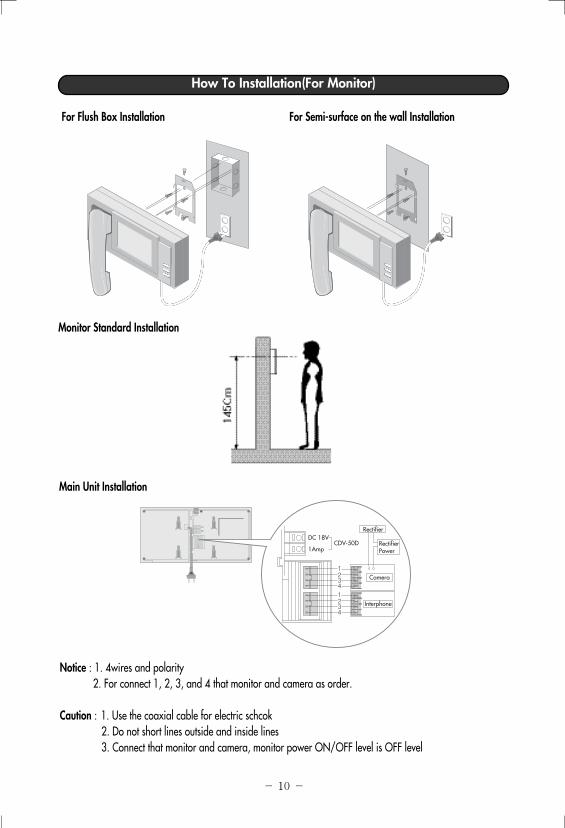
How To Installation(For Monitor)
For Flush Box Installation For Semi-surface on the wall Installation
Monitor Standard Installation
Main Unit Installation
Notice : 1. 4wires and polarity2. For connect 1, 2, 3, and 4 that monitor and camera as order.
Caution : 1. Use the coaxial cable for electric schcok2. Do not short lines outside and inside lines3. Connect that monitor and camera, monitor power ON/OFF level is OFF level
Rectifier
RectifierPower
Camera
Interphone
DC 18VCDV-50D
1Amp

‐ 11 ‐
Procaution before InstallationDo not Aim The Camera At The SunDo not aim the camerr at the sun or point it at the sun even if you are not shooting.Do not Shoot Intense LightFraming intense light such as a spotlight may cause bloom or smear.Never Touch Internal PartsDo not touch the internal parts of the camera other than that parts specified. Otherwise, the camera maymalfunction.Check The Ambient Temperature And HumidityAvoid using the camera where the temperature is hotter or colder than specified. Otherwise, the quality ofimages may deteriorate or internal parts may be affected. Special care is required to use the camera at hightemperature and humidity.
How To Installation (For Camera)
For Flush Box Installation For Semi-surface on the wall Installation
Camera Standard Installation(For Height/Up/Down/Horizontal Angular)
Notice : If you have questions connection the wires for installation following up, Contact to seller or qualified service personnel before not operating.
Up
Down
8
Camera
CameraScrew
CameraScrew
CameraScrew
Flush Box
BracketFixed Screw
‐ 12 ‐
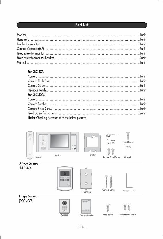
Part List
Monitor ..............................................................................................................................................1unitHand set ............................................................................................................................................1unitBracket for Monitor .............................................................................................................................1unitConnect Connector(4P)........................................................................................................................2unitFixed screw for monitor .......................................................................................................................1unitFixed screw for monitor bracket ...........................................................................................................2unitManual ..............................................................................................................................................1unit
For DRC-4CACamera ................................................................................................................................1unitCamera Flush Box .................................................................................................................1unitCamera Screw ......................................................................................................................2unitHexagon Lench .....................................................................................................................1unitFor DRC-40CS Camera ................................................................................................................................1unitCamera Bracket ....................................................................................................................1unitCamera Fixed Screw .............................................................................................................1unitFixed Screw for Camera ........................................................................................................2unitNotice:Checking accessories as the below pictures
Monitor Bracket
Connector(4p-2 EA)
Bracket Fixed Screw Manual
ManualCDV-50
Bracket Fixed Screw
Hexagon Lench
Fixed Screw
Fixed Screw
Camera ScrewFlush Box
Handset
Camera Camera Bracket
A Type Camera(DRC-4CA)
B Type Camera(DRC-40CS)
‐ 13 ‐
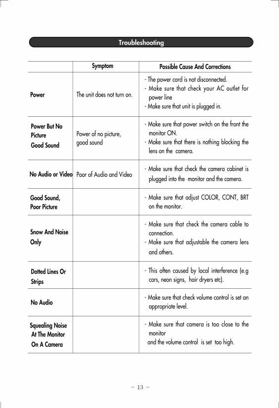
Troubleshooting
- The power cord is not disconnected. - Make sure that check your AC outlet for
power line- Make sure that unit is plugged in.
- Make sure that power switch on the front themonitor ON.
- Make sure that there is nothing blocking thelens on the camera.
- Make sure that check the camera cabinet isplugged into the monitor and the camera.
- Make sure that adjust COLOR, CONT, BRTon the monitor.
- Make sure that check the camera cable toconnection.
- Make sure that adjustable the camera lensand others.
- This often caused by local interference (e.gcars, neon signs, hair dryers etc).
- Make sure that check volume control is set anappropriate level.
- Make sure that camera is too close to themonitor and the volume control is set too high.
Power
Power But NoPictureGood Sound
No Audio or Video
Good Sound,Poor Picture
Snow And NoiseOnly
Dotted Lines OrStrips
No Audio
Squealing NoiseAt The MonitorOn A Camera
The unit does not turn on.
Power of no picture, good sound
Poor of Audio and Video
Symptom Possible Cause And Corrections
‐ 14 ‐
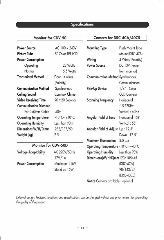
External design, Features, functions and specifications can be changed without any prior notice., for promotingthe quality of the product.
Specifications
Power Source AC 100 ~ 240V,Picture Tube 5” Color TFT-LCDPower Consumption
Operating 23 WattsNormal 5.5 Watts
Transmitted Method Door : 4 wires(Polarity)
Communication Method Synchronous Calling Sound Commax Chime Video Receiving Time 90±20 SecondsCommunication Distance
For 0.65mm Cable 50mOperating Temperature -10。C~ +40。COperating Humidity Less than 90%Dimensions(W/H/D)mm 283/137/50Weight (kg) 2.5
Voltage Adaptability AC 220V/50Hz 17V/1A
Power Consumption Maximum 1.5WStand by 15W
Mounting Type Flush Mount TypeMount (DRC-4CS)
Wiring 4 Wires (Polarity)Power Source DC 13V (Power
from monitor)Communication Method Synchronous
CommunicationPick-Up Device 1/4” Color
CCD CameraScanning Frequency Horizontal
:15.75KHz Vertical : 60Hz
Angular Field of Lens Horizontal : 68。Vertical : 55。
Angular Field of Adjust Up : 12.5。Down : 12.5。
Minimum lllumination 3.0 LuxOperating Temperature -10。C ~+40。COperating Humidity Less than 90%Dimensions(W/H/D)mm123/185/45
(DRC-4CA)98/142/37(DRC-40CS)
Notice:Camera available - optional
Monitor for CDV-50
Monitor for CDV-50D
Camera for DRC-4CA/40CS

Commax User ManualJul 2002CDV-50 Rev.A
513-11, Sangdaewon-dong, Jungwon-ku, Seongnam-city,Kyungki-do, Korea
Tel.; +82-31-7393-540~550Fax.; +82-31-745-2133Web site; www.commax.co.kr
Printed In Korea