
WIB1 CT Powered Time Overcurrent and Earth Current Relay1.1 Information Concerning Liability and...
56
WIB1 CT Powered Time Overcurrent and Earth Current Relay Manual WIB1 (Revision H)
Transcript of WIB1 CT Powered Time Overcurrent and Earth Current Relay1.1 Information Concerning Liability and...

WIB1
CT Powered Time Overcurrent and Earth Current Relay
Manual WIB1 (Revision H)

Woodward Manual WIB1 EN
2 DOK-TD-WIB1EN_Rev.H
Contents
1. Comments on the manual ........................................................................... 4 1.1 Information Concerning Liability and Warranty................................................................... 4 1.2 IMPORTANT DEFINITIONS ............................................................................................... 5 1.3 Electrostatic Discharge Awareness .................................................................................... 6
2. Introduction .................................................................................................. 7 2.1 How to use this instruction .................................................................................................. 7 2.2 Introductory remarks on the WIB1 ...................................................................................... 7 2.3 Product description ............................................................................................................. 8
3. Handling, Installation and Outside Dimensions ........................................ 9 3.1 General information ............................................................................................................ 9
3.1.1 Upkeep of the relay ......................................................................................................... 9 3.1.2 Storage ........................................................................................................................... 9 3.1.3 Electrostatic discharge .................................................................................................... 9
3.2 Installation of the relay ........................................................................................................ 9 3.3 Outside dimensions .......................................................................................................... 10 3.4 Connection Diagram ......................................................................................................... 10
4. Operating instructions .............................................................................. 13 4.1 General information on the WIB1 ..................................................................................... 13 4.2 User interface ................................................................................................................... 14
4.2.1 WIB12PE ...................................................................................................................... 14 4.2.2 WIB12FE ....................................................................................................................... 15 4.2.3 WIB12PEB .................................................................................................................... 16
4.3 CTs for the WIB1 .............................................................................................................. 17
5. Technical Data, Characteristics and Features......................................... 18 5.1 Protective functions .......................................................................................................... 18
5.1.1 Minimal operating current and rated primary current.................................................... 18 5.1.2 Phase time over current protection ............................................................................... 19 5.1.3 Blocking stage............................................................................................................... 20 5.1.4 Earth current protection ................................................................................................ 21
5.2 Default Settings ................................................................................................................ 22 5.2.1 WIB12FE und WIB12PE ............................................................................................... 22 5.2.2 WIB12PEB .................................................................................................................... 22
5.3 Routine safety check (only WIB12PE) .............................................................................. 22 5.4 Fault value memory .......................................................................................................... 22 5.5 Communication ................................................................................................................. 23
5.5.1 Communication via PC adapter .................................................................................... 23 5.5.2 WIC1PC2 Adapter ........................................................................................................ 23 5.5.3 WIC1PC3 Adapter ........................................................................................................ 23
5.6 Inputs and outputs ............................................................................................................ 23 5.6.1 Remote trip input .......................................................................................................... 24 5.6.2 Impulse output for the tripping coil ................................................................................ 24 5.6.3 Impulse output for the flag indicators ............................................................................ 24 5.6.4 Earthing ......................................................................................................................... 24
5.7 Technical Data .................................................................................................................. 25 5.7.1 Common Data ............................................................................................................... 25 5.7.2 Temperature Range ...................................................................................................... 25 5.7.3 Accuracy (acc. to IEC60255-151) ............................................................................... 25 5.7.4 Time Accuracy (acc. to IEC60255-151) ....................................................................... 25
5.8 Design standards: ............................................................................................................. 26 5.8.1 High voltage tests: ........................................................................................................ 26 5.8.2 EMC immunity tests: ..................................................................................................... 27 5.8.3 EMC emission tests: ..................................................................................................... 27 5.8.4 Mechanical tests: .......................................................................................................... 28 5.8.5 Environmental tests: ..................................................................................................... 28 5.8.6 Outside dimension of CTs ............................................................................................ 29

Manual WIB1 EN Woodward
DOK-TD-WIB1EN_Rev.H 3
5.9 Characteristics and times .................................................................................................. 31 Characteristic curves ......................................................................................................... 31 5.9.1 ........................................................................................................................................... 31 5.9.2 Calculation formula for IMT characteristics ................................................................... 33 5.9.3 Trip coil output ............................................................................................................... 34 5.9.4 Flag Indicators ............................................................................................................... 34
5.10 Description of application .................................................................................................. 35 5.10.1 Foreword ................................................................................................................... 35
5.11 Selection of the CT transformation voltage ratio ............................................................... 37 5.12 Adjustment instruction for inverse characteristic ............................................................... 38
6. Commissioning and Maintenance ............................................................ 41 6.1.1 Important note ............................................................................................................... 41
6.2 Accessories for commissioning work ................................................................................ 41 6.3 Criteria to be taken into account for protection devices fed by CT’s............................... 41 6.4 Special features for the WIB1 test..................................................................................... 42 6.5 Selection of the secondary test system ............................................................................ 42 6.6 Checks during commissioning .......................................................................................... 42
6.6.1 Wiring checks ................................................................................................................ 42 6.6.2 WIB1 adjustment ........................................................................................................... 43
6.7 Functional Test .................................................................................................................. 43 6.7.1 Test Currents ................................................................................................................. 44 6.7.2 Switching points for the overcurrent steps I> ................................................................ 44 6.7.3 Switching points for the short-circuit steps I>> (only WIB12FE and WIB12PE) ........... 45 6.7.4 Switching points for the blocking function steps IBLOCK (only WIB12PEB)..................... 45
6.8 Special features for earth current tests ............................................................................. 46 6.8.1 Switching points for the earth current step IE> .............................................................. 46 6.8.2 Switching points for the earth current short-circuit step IE>> ........................................ 46
6.9 Test procedure by way of example ................................................................................... 47 6.10 Maintenance ...................................................................................................................... 49
6.10.1 Faults ......................................................................................................................... 49 6.10.2 Repair work ............................................................................................................... 49
7. Product Specific Features ......................................................................... 50 7.1 Assignment of terminals .................................................................................................... 50
7.1.1 Assignment of terminals at WIB12PE and WIB12PEB ................................................. 50 7.1.2 Assignment of terminals at WIB12FE ........................................................................... 50 7.1.3 Earthing ......................................................................................................................... 50
7.2 Current transformer ........................................................................................................... 51
8. Annex .......................................................................................................... 53 8.1 Dimensional drawing relay ................................................................................................ 53 8.2 Dimensional drawing flag indicator ................................................................................... 53 8.3 Order form ......................................................................................................................... 54 8.4 Commissioning form ......................................................................................................... 55
8.4.1 Parameter Setting WIB12FE and WIB12PE ................................................................. 55 8.4.2 Parameter Setting WIB12PEB ...................................................................................... 55

Woodward Manual WIB1 EN
4 DOK-TD-WIB1EN_Rev.H
1. Comments on the manual This manual explains in general the tasks of device planning, parameter setting, installation, com-missioning, operation and maintenance of the WIB1 device. The manual serves as working basis for:
Engineers in the protection field, commissioning engineers, people dealing with setting, testing and maintenance of protection and control devices, as well as trained personnel for electrical installations and power stations.
All functions concerning the type code will be defined. Should there be a description of any func-tions, parameters or inputs/outputs which do not apply to the device in use, please ignore that in-formation. All details and references are explained to the best of our knowledge and are based on our experi-ence and observations. This manual describes the (optionally) full featured versions of the devices. All technical information and data included in this manual reflect their state at the time this docu-ment was issued. We reserve the right to carry out technical modifications in line with further de-velopment without changing this manual and without previous notice. Hence no claim can be brought based on the information and descriptions this manual includes. Text, graphic and formulae do not always apply to the actual delivery scope. The drawings and graphics are not true to scale. We do not accept any liability for damage and operational failures caused by operating errors or disregarding the directions of this manual. No part of this manual is allowed to be reproduced or passed on to others in any form, unless Woodward Kempen GmbH have approved in writing. This user manual is part of the delivery scope when purchasing the device. In case the device is passed on (sold) to a third party, the manual has to be handed over as well. Any repair work carried out on the device requires skilled and competent personnel who need to be well aware especially of the local safety regulations and have the necessary experience for working on electronic protection devices and power installations (provided by evidence).
1.1 Information Concerning Liability and Warranty
Woodward Kempen GmbH does not accept any liability for damage resulting from conversions or changes carried out on the device or planning (projecting) work, parameter setting or adjustment changes done by the customer. The warranty expires after a device has been opened by others than Woodward Kempen GmbH specialists. Warranty and liability conditions stated in Woodward Kempen GmbH General Terms and Condi-tions are not supplemented by the above mentioned explanations.

Manual WIB1 EN Woodward
DOK-TD-WIB1EN_Rev.H 5
1.2 IMPORTANT DEFINITIONS
The signal definitions shown below serve the safety of life and limb as well as for the appropriate operating life of the device.
DANGER indicates a hazardous situation which, if not avoided, will result in death or serious injury.
WARNING indicates a hazardous situation which, if not avoided, could result in death or serious injury.
CAUTION, used with the safety alert symbol, indicates a hazardous situation which, if not avoided, could result in minor or moderate injury.
NOTICE is used to address practices not related to personal injury.
CAUTION, without the safety alert symbol, is used to address practices not related to personal injury.

Woodward Manual WIB1 EN
6 DOK-TD-WIB1EN_Rev.H
1.3 Electrostatic Discharge Awareness
All electronic equipment is electro static-sensitive, some components more than others. To protect these components from electro static damage, you must take special precautions to minimize or eliminate electrostatic discharges.
Follow these precautions when working with or near the control.
1. Before doing maintenance on the electronic control, discharge the static electricity on your body to ground by touching and holding a grounded metal object (pipes, cabinets, equipment, etc.).
2. Avoid the build-up of static electricity on your body by not wearing clothing made of synthetic materials. Wear cotton or cotton-blend materials as much as possible because these do not store static electric charges as much as synthetics.
3. Keep plastic, vinyl, and Styrofoam materials (such as plastic or Styrofoam cups, cup holders, cigarette packages, cellophane wrappers, vinyl books or folders, plastic bottles, and plastic ash trays) away from the control, the modules, and the work area as much as possible.
4. Do not remove any printed circuit board (PCB) from the control cabinet unless absolutely necessary. If you must remove the PCB from the control cabinet, follow these precautions:
Do not touch any part of the PCB except the edges.
Do not touch the electrical conductors, the connectors, or the components with conductive devices or with your hands.
When replacing a PCB, keep the new PCB in the plastic antistatic protective bag it comes in until you are ready to install it. Immedi-ately after removing the old PCB from the control cabinet, place it in the antistatic protective bag.
To prevent damage to electronic components caused by improper handling, read and observe the precautions in Woodward manual 82715, Guide for Handling and Protection of Electronic Controls, Printed Circuit Boards, and Modules.
Woodward Kempen GmbH reserves the right to update any portion of this publication at any time. Information provided by Woodward Kempen GmbH is believed to be correct and relia-ble. However, no responsibility is assumed by Woodward Kempen GmbH unless otherwise expressly undertaken.
© Woodward 2015 All Rights Reserved

Manual WIB1 EN Woodward
DOK-TD-WIB1EN_Rev.H 7
2. Introduction Woodward Kempen GmbH protection relays of the WI-LINE are offering time over current protec-tive functions and earth fault protective functions in the well-proven technique for CT powered pro-tection relays. As combination of a compact protection relay and related current transformers, the WIB1 system was especially developed for compact MV switchboards with circuit breakers.
2.1 How to use this instruction In this instruction the technical description of all WIB1 versions is included. The user is given a comprehensive insight into the various applications, the selection, installation, setting of parame-ters and putting into operation of the WIB1. This instruction is divided into the following sections: Chapter 1; Introduction Chapter 2; Handling, installation and outside dimensions Chapter 3; Operating instructions Chapter 4; Technical data, characteristics and features Chapter 5; Product specific features Chapter 6; Annex; Dimensional drawing and flag indicator, Order form and commissioning form
OUT-OF-DATE PUBLICATION This publication may have been revised or updated since this copy was produced. To verify that you have the latest revision, be sure to check the Woodward Kempen GmbH website: http://www.woodward.com/ page Products / Protection RelaysIf your publi-cation is not there, please contact your customer service representative to get the latest copy.
2.2 Introductory remarks on the WIB1 The requirements on MS distribution stations with circuit breakers call for a robust protection relay which is optimized accordingly and an integral part of the respective switchboard. The WIB1 is a time over current relay Woodward has developed specifically for such requirements. The WIB1 is a CT-powered protection relay with minimal space requirement which complies with the highest demands on a digital protection device. Simple but safe wiring, high electromagnetic in-terference immunity, uncomplicated adjustment and the ability to scale to different power quantities of the switchboard, helping the switchgear manufacturer to minimize costs. By developing the WIB1 we are also able to present a protective system with a guaranteed maintenance-free period of 25 years, the same as for the switchboard.

Woodward Manual WIB1 EN
8 DOK-TD-WIB1EN_Rev.H
2.3 Product description The WIB1 is a CT-powered protection relay with inverse time and definite time protection charac-teristics and is specifically designed for switchboards with CBs and small rated output currents. Together the specific CTs and the WIC1 form a joint protective system. A low-energy coil is needed for realizing trip of the CB. Parameter setting can be done in user-friendly ways. By means of casting all electronic compo-nents incl. the housing are safely protected against climatic and mechanic influences. In the WIB1 the following protection functions are realized:
3 phase definite time over current and short-circuit protection with variable tripping times (ANSI 50/51)
3 phase over current protection with selectable inverse time characteristics and definite time short-circuit current element (ANSI 50/51)
definite time earth over current and earth short-circuit protection by internal calculation (ANSI 50N/51N)
earth over current protection with selectable inverse time characteristics and instantaneous short-circuit current element (ANSI 50N/51N)
WIB1 is available in three different versions WIB12PE, WIB12PEB and WIP12FE.
The -FE version has less functionality: o Fixed connectors instead of pluggable connectors o Without Routine safety check (I>> backup protection) o No plug-in connectors for CT test windings on board
The -PEB version has different functionality: o The 3 phase short-circuit element is not available o The complete tripping can be blocked by parameter IBLOCK depending on input current o Without Routine safety check (I>> backup protection)

Manual WIB1 EN Woodward
DOK-TD-WIB1EN_Rev.H 9
3. Handling, Installation and Outside Dimensions
3.1 General information
3.1.1 Upkeep of the relay As a rule protection relays are of robust construction and the WIB1 in particular allows operation under extreme environmental conditions. But despite these facts, the WIB1 should be handled with the necessary care during installation and commissioning. Immediately after receipt of the relay it should be checked for possible damage inflicted during transportation. Any transport damage has to be notified to the transport firm handling the consignment. Those relays which are not installed immediately should be stored in their original package (styrofoam).
3.1.2 Storage If the relay is not used directly it has to be stored in its original packing. Permissible temperatures during storing are -40°C up to +85°C. The storage place should be dry.
3.1.3 Electrostatic discharge The electronic components used in the relay react very sensitive to electrostatic discharge but they are absolute safely placed inside the plastic housing. Additionally all electronic components are well protected by means of casting. Hence it is practical impossible that components are damaged by ESD. There are no settings or calibrating appliances inside the housing, which would call for opening the device by the user. The housing is hermetically sealed and cannot be opened without causing damage.
3.2 Installation of the relay By using the three 7mm drill holes, the relay is directly mounted onto the mounting plate. Detailed drawing with all measurements can be found under chapter 8.1.

Woodward Manual WIB1 EN
10 DOK-TD-WIB1EN_Rev.H
3.3 Outside dimensions All WIB1 types are of standardized design. Weight: 700 g Dimensions: (Width x Height x Depth) 125 x 170 x40 mm
3.4 Connection Diagram
1
2 3 gn/ge
1
2 3 gn/ge
S1
S2 C D
S1
S2 C D
S1
S2 C D
WIB12PE
1
2 3 gn/ge
L1 L2 L3
TC+
TC-
230V
N ~
Energiearme / low energy
Auslösespule / tripping coil
115V
PE
FI+
FI -
Schauzeichen Fehler im Phasenstrompfad Flag indicator failure in phase path
Eingang Fernauslöser
input remote trip
FE+
FE-
Schauzeichen Fehler im Erdstrompfad Flag indicator failure in earth path
Figure 3.1: Connecting diagram WIB12PE and WIB12PEB

Manual WIB1 EN Woodward
DOK-TD-WIB1EN_Rev.H 11
1
2
1
2
S1
S2
S1
S2
S1
S2
WIB12FE
1
2
L1 L2 L3
TC+
TC-
230V
~
Energiearme / low energy
Auslösespule / tripping coil
115V
PE
FI+
FI -
Schauzeichen Fehler im Phasenstrompfad Flag indicator failure in phase path
Eingang Fernauslöser
input remote trip
FE+
FE-
Schauzeichen Fehler im Erdstrompfad Flag indicator failure in earth path
N
Figure 3.2: Connection diagram WIB12FE
Woodward Manual WIB1 EN
12 DOK-TD-WIB1EN_Rev.H
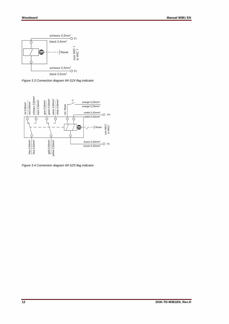
Figure 3.3 Connection diagram WI-SZ4 flag indicator
violet 0,25mm²
violett 0,25mm²
brown 0,25mm²
braun 0,25mm²
orange 0,25mm²
orange 0,25mm²
weis
s 0
,50m
m²
white 0
,50m
m²
gre
en 0
,50m
m²
grü
n 0
,50m
m²
red 0
,50m
m²
rot 0,5
0m
m²
back 0
,50m
m²
schw
arz
0,5
0m
m²
blu
e 0
,50m
m²
bla
u 0
,50m
m²
yello
w 0
,50m
m²
gelb
0,5
0m
m²
Reset
zum
WIC
1
to W
IC1
ext. R
eset
FI+
FI-
Figure 3.4 Connection diagram WI-SZ5 flag indicator
Manual WIB1 EN Woodward
DOK-TD-WIB1EN_Rev.H 13
4. Operating instructions
4.1 General information on the WIB1 All available versions of the WIB1 relay are a high-tech and cost-optimized protection for MV switchboards. Specifically in compact switchboards, the WIB12PE and WIB12FE protection system in combina-tion with a circuit breaker can replace the combination of load-break-switch with HV fuses. Thereby in particular the overload protection for the attached unit is improved clearly. When power distribution networks are extended more and more high powered transformers are used and here HV fuses are inadmissible. For such applications the WIB1 protection system is an optimal replacement. If in special applications a breaker is used in combination with HV fuses the WIB12PEB functions as over current and earth current protection device in combination with the breaker. The short cir-cuit protection is done by the HV fuses. To protect the breaker from damage by switching too high currents the WIB12PEB has a settable current level blocking the WIB12PEB from trip. The WIB1 is provided with three analogue measuring inputs (3x phase current). The current meas-uring inputs are specially adjusted to the CTs allocated to the WIB1 protection system. There are 6 different CT ratios available for the protection system WIB1 which are conditional on the rated sys-tem current. The successive development towards the application time over current protection makes the system very user friendly. Reading of tripping values is done via the integrated interface. For this the user has one PC adapter and the software “WI-Soft2” at hand. The software is availa-ble for installation on a WINDOWS PC. Setting of protection parameters is done by means of DIP switches Cumulative current formation for earth current detection is programmed in the relay. The earth cur-rent is calculated from the three phase currents. The WIB1 is provided with an input for remote tripping to which 115 VAC or 230 VAC can be con-nected. Tripping is realized via the electric impulse output after max. 1s. A mechanical flag indicator WI1SZ4 can be installed for optical signaling occurrence of trip condi-tions. Trip conditions are phase fault or earth fault and can be indicated separately. Furthermore it is possible to signal the trip events potentially free via the flag indicator WI1-SZ5. For this purpose the flag indicator is equipped with two changeover contacts. The activation of the relay is signaled by a LED which is above the switches and protected by the clear plastic cover.

Woodward Manual WIB1 EN
14 DOK-TD-WIB1EN_Rev.H
4.2 User interface The adjustment of protective functions can be done via DIP switches; The setting of parameters via interface is not possible, but it is possible to read-out the stored fault values as well as the setting values. The interface for this version can be found at the left of the relay and additionally above the DIP switch block.
4.2.1 WIB12PE
Switch No. Setting parameter
1-1 – 1-3 IS: Rated CT current
1-4 – 1-5 Choice of characteristics for phase path
1-6 – 2-1 I>: Pick-up value of the definite time over current element or start value of the inverse time characteristic.
2-2 – 2-4 tI>: Tripping time of the definite time over current element or factor “a” of the inverse time characteristic
2-5 – 2-8 I>>: Pick-up value of the short-circuit element
3-1 – 3-4 tI>>: Tripping time of the short-circuit element
3-5 – 3-6 Choice of characteristics for earth path
3-7 – 4-2 IE>: Pick-up value of the definite time earth over current element or start value of the inverse time characteristic.
4-3 – 4-5 tIE>: Tripping time of the definite time earth over current element or factor “a” of the inverse time characteristic.
4-6 – 4-8 IE>>: Pick-up value of time earth short circuit current element
Figure 4.1: Front view WIB12PE

Manual WIB1 EN Woodward
DOK-TD-WIB1EN_Rev.H 15
4.2.2 WIB12FE
Switch No. Setting parameter
1-1 – 1-3 IS: Rated CT current
1-4 – 1-5 Choice of characteristics for phase path
1-6 – 2-1 I>: Pick-up value of the definite time over current element or start value of the inverse time characteristic.
2-2 – 2-4 tI>: Tripping time of the definite time over current element or factor “a” of the inverse time characteristic
2-5 – 2-8 I>>: Pick-up value of the short-circuit element
3-1 – 3-4 tI>>: Tripping time of the short-circuit element
3-5 – 3-6 Choice of characteristics for earth path
3-7 – 4-2 IE>: Pick-up value of the definite time earth over current element or start value of the inverse time characteristic.
4-3 – 4-5 tIE>: Tripping time of the definite time earth over current element or factor “a” of the inverse time characteristic.
4-6 – 4-8 IE>>: Pick-up value of time earth short circuit current element
Figure 4.2: Front view WIB12FE

Woodward Manual WIB1 EN
16 DOK-TD-WIB1EN_Rev.H
4.2.3 WIB12PEB
Switch No. Setting parameter
1-1 – 1-3 IS: Rated CT current
1-4 – 1-5 Choice of characteristics for phase path
1-6 – 2-1 I>: Pick-up value of the definite time over current element or start value of the inverse time characteristic.
2-2 – 2-4 tI>: Tripping time of the definite time over current element or factor “a” of the inverse time characteristic
2-5 – 2-8 IBLOCK: Pick-up value to block tripping
3-1 – 3-4 (Not used)
3-5 – 3-6 Choice of characteristics for earth path
3-7 – 4-2 IE>: Pick-up value of the definite time earth over current element or start value of the inverse time characteristic.
4-3 – 4-5 tIE>: Tripping time of the definite time earth over current element or factor “a” of the inverse time characteristic.
4-6 – 4-8 IE>>: Pick-up value of time earth short circuit current element
Figure 4.3: Front view WIB12PEB

Manual WIB1 EN Woodward
DOK-TD-WIB1EN_Rev.H 17
4.3 CTs for the WIB1 There are six different wide-range CTs for the protection system WIB1. Dependent on the rated primary power and voltage of the system, the following CTs can be offered:
CT Type Rated CT current IS
WIC1-WE1 8 – 15 A
WIC1-W1 8 – 15 A
WIC1-WE2 16 – 30 A
WIC1-W2 16 – 30 A
WIC1-W3 32 – 60 A
WIC1-W4 64 – 120 A
WIC1-W5 128 – 240 A
WIC1-W6 256 – 480 A
The protection relay can be set to the respective operating current of the switchboard by parameter Is. Reference on the calculation of the protective setting values resulting from this is made in chap-ter “Description of Application”. Current transformer WIC1-WE1 and WIC1-WE2 In case of small values of the primary currents the user can choose for two current transformers with equal ratings but different characteristics of transmission –WE1 or W1 (WE2 or W2). It is typical reaction of self-powered protection relays such as WIB1 that there will be a non-linear transmission characteristic of the relay in case of small primary currents. This will effect on the ac-curacy of the whole system if the current transformer is a W2 type and primary current values are less than 20 A. Generally less accuracy will be accepted for phase current protection so that the CT W2 represents an inexpensive solution. If there will be required a higher accuracy or in case of an active earth current protection element it is re-commended to use a WE1 (WE2) mixed core type CT based on MU metal. In the lower opera-tion range this CT type is more precise than the ordinary WI1 (W2) type.

Woodward Manual WIB1 EN
18 DOK-TD-WIB1EN_Rev.H
5. Technical Data, Characteristics and Features
5.1 Protective functions
5.1.1 Minimal operating current and rated primary current In order to operate reliably, the WIB1 - as all CT-powered protection relays - needs a minimal cur-rent flowing constantly in one of the phases. This minimal current is the smallest rated CT current (Is) x 0.9 listed in table. The real rated current of the operating component to be protected is adjusted by parameter Is . All further settings at the protection relay refer to the adjusted IS. This is to be described in the follow-ing example; Example for WIB12FE and WIB12PE: Setting Is = 40 A, CT type W3, 32 to 60 A Setting I>: 1.1 x Is = 1.1 x 40 A = 44 A Setting I>>: 10 x Is = 10 x 40 A = 400 A Setting IE>: 0.2 x Is = 0.2 x 40 A = 8 A Setting IE>>: 2 x Is = 2 x 40 A = 80 A Example for WIB12PEB: Setting Is = 20 A, CT type W2, 16 to 30 A Setting I>: 1.2 x Is = 1.2 x 20 A = 24 A Setting IBLOCK: 8 x Is = 8 x 20 A = 160 A Setting IE>: 0.4 x Is = 0.4 x 20 A = 8 A Setting IE>>: 1 x Is = 1 x 20 A = 20 A DIP switch 1-1 – 1-3: The following currents are adjusted by DIP switches: DIP 1-1 OFF ON OFF ON OFF ON OFF ON
DIP 1-2 OFF OFF ON ON OFF OFF ON ON
DIP 1-3 OFF OFF OFF OFF ON ON ON ON
WIC1-W1 WIC1-WE1
8 9 10 11 12 13 14 15
WIC1-W2 WIC1-WE2
16 18 20 22 24 26 28 30
WIC1-W3 32 36 40 44 48 52 56 60
WIC1-W4 64 72 80 88 96 104 112 120
WIC1-W5 128 144 160 176 192 208 224 240
WIC1-W6 256 288 320 352 384 416 448 480
Table 5.1
*Note: All values are primary values in Ampere

Manual WIB1 EN Woodward
DOK-TD-WIB1EN_Rev.H 19
5.1.2 Phase time over current protection
The min. tripping time when switched on to a failure is subject to the fault current level. See the following diagram. The diagram shows the tripping time under worst conditions like ageing, temperature.
Im = Minimum current With the WIB1 protection system minimal tripping times of 40 ms can be achieved. Time correction of current 0 ≤45 ms of current > Im ≥35 ms Disengaging time <30 ms
Minimale Auslösezeiten
Minimum tripping times
10
100
1000
0 5 10 15 20
t [m
s]
einphasigeSpeisung /single phasesupply
zweiphasigeSpeisung /dual phasesupply
dreiphasigeSpeisung /three phasesupply
Im
I

Woodward Manual WIB1 EN
20 DOK-TD-WIB1EN_Rev.H
The adjustment of values is done according to the tables listed below: I_Characteristic curve = DIP-Switch 1-4 – 1-5 DIP 1-4 OFF ON OFF ON
DIP 1-5 OFF OFF ON ON
Characteristic DEFT N-INV V-INV E-INV
Phase path
I> = DIP-Switch 1-6 – 2-1 DIP 1-6 OFF ON OFF ON OFF ON OFF ON OFF ON OFF ON OFF ON OFF ON
DIP 1-7 OFF OFF ON ON OFF OFF ON ON OFF OFF ON ON OFF OFF ON ON
DIP 1-8 OFF OFF OFF OFF ON ON ON ON OFF OFF OFF OFF ON ON ON ON
DIP 2-1 OFF OFF OFF OFF OFF OFF OFF OFF ON ON ON ON ON ON ON ON
x Is 0.9 0.95 1 1.05 1.1 1.15 1.2 1.3 1.4 1.5 1.6 1.8 2 2.25 2.5 Exit
tI> = DIP-Switch 2-2 – 2-4 DIP 2-2 OFF ON OFF ON OFF ON OFF ON
DIP 2-3 OFF OFF ON ON OFF OFF ON ON
DIP 2-4 OFF OFF OFF OFF ON ON ON ON
time (s) 0.1 0.2 0.3 0.4 0.5 0.6 1 2
Factor “a” 0.05 0.1 0.2 0.3 0.4 0.6 0.8 1
I>> = DIP-Switch 2-5 – 2-8 (only WIB12FE and WIB12PE) DIP 2-5 AUS EIN AUS EIN AUS EIN AUS EIN AUS EIN AUS EIN AUS EIN AUS EIN
DIP 2-6 AUS AUS EIN EIN AUS AUS EIN EIN AUS AUS EIN EIN AUS AUS EIN EIN
DIP 2-7 AUS AUS AUS AUS EIN EIN EIN EIN AUS AUS AUS AUS EIN EIN EIN EIN
DIP 2-8 AUS AUS AUS AUS AUS AUS AUS AUS EIN EIN EIN EIN EIN EIN EIN EIN
x Is 1 2 3 4 5 6 7 8 9 10 12 14 16 18 20 EXIT
tI>> = DIP-Switch 3-1 – 3-4 (only WIB12FE and WIB12PE) DIP 3-1 OFF ON OFF ON OFF ON OFF ON OFF ON OFF ON OFF ON OFF ON
DIP 3-2 OFF OFF ON ON OFF OFF ON ON OFF OFF ON ON OFF OFF ON ON
DIP 3-3 OFF OFF OFF OFF ON ON ON ON OFF OFF OFF OFF ON ON ON ON
DIP 3-4 OFF OFF OFF OFF OFF OFF OFF OFF ON ON ON ON ON ON ON ON
time (s) 0,04 0,07 0,1 0,15 0,2 0,25 0,3 0,4 0,6 0,8 1,0 1,4 1,8 2,2 2,6 3,0
Information: At WIB12PEB HEX-Switch 6/DIP-Switch 3-1 – 3-4 is not used
5.1.3 Blocking stage IBLOCK = DIP-Switch 2-5 – 2-8 (only WIB12PEB) DIP 2-5 AUS EIN AUS EIN AUS EIN AUS EIN AUS EIN AUS EIN AUS EIN AUS EIN
DIP 2-6 AUS AUS EIN EIN AUS AUS EIN EIN AUS AUS EIN EIN AUS AUS EIN EIN
DIP 2-7 AUS AUS AUS AUS EIN EIN EIN EIN AUS AUS AUS AUS EIN EIN EIN EIN
DIP 2-8 AUS AUS AUS AUS AUS AUS AUS AUS EIN EIN EIN EIN EIN EIN EIN EIN
x Is 1 1,5 2 3 4 5 6 7 8 9 10 12 14 16 18 20

Manual WIB1 EN Woodward
DOK-TD-WIB1EN_Rev.H 21
5.1.4 Earth current protection IE_Characteristic curve = DIP-Switch 3-5 – 3-6 DIP 3-5 OFF ON OFF ON
DIP 3-6 OFF OFF ON ON
Characteristic DEFT N-INV V-INV E-INV
Earth path
IE> DIP-Switch 3-7 – 4-2 DIP 3-7 OFF ON OFF ON OFF ON OFF ON OFF ON OFF ON OFF ON OFF ON
DIP 3-8 OFF OFF ON ON OFF OFF ON ON OFF OFF ON ON OFF OFF ON ON
DIP 4-1 OFF OFF OFF OFF ON ON ON ON OFF OFF OFF OFF ON ON ON ON
DIP 4-2 OFF OFF OFF OFF OFF OFF OFF OFF ON ON ON ON ON ON ON ON
x Is 0.2 0.3 0.4 0.5 0.6 0.7 0.8 0.9 1.0 1.2 1.4 1.6 1.8 2.0 2.5 Exit
tIE> = /DIP-Switch 4-3 – 4-5 DIP 4-3 OFF ON OFF ON OFF ON OFF ON
DIP 4-4 OFF OFF ON ON OFF OFF ON ON
DIP 4-5 OFF OFF OFF OFF ON ON ON ON
time (s) 0.1 0.2 0.3 0.4 0.5 0.6 1 2
Factor “a” 0.05 0.1 0.2 0.3 0.4 0.6 0.8 1
IE>> DIP-Switch 4-6 – 4-8 DIP 4-6 OFF ON OFF ON OFF ON OFF ON
DIP 4-7 OFF OFF ON ON OFF OFF ON ON
DIP 4-8 OFF OFF OFF OFF ON ON ON ON
x Is 1 2 3 4 5 6 7 EXIT
tIE>> = 0.10 s (fixed)
Each earth current stage is blocked if actually measured phase current exceeds 20x set trip level: - The WIB don’t trip at phase currents > 20x IE> when I>, I>> and IE>> stages are disabled
I>
I>>
I> = EXIT
I>> = EXIT
≥1TRIP
IE>
IE>>
IE> = EXIT
IE>> = EXIT
Ext.
Trip
Block if I > 20x IE>>
Block if I > 20x IE>
I>
IBLOCK
IE>
IE>>
I> = EXIT
IE> = EXIT
IE>> = EXIT Block if I > 20x IE>>
Block if I > 20x IE>
≥1TRIP
Ext.
Trip Figure 5.1: Trip logic WIB12FE und WIB12PE Figure 5.1.a: Trip logic WIB12PEB
The blocking function is implemented due to accuracy of earth current calculation in combination with the setting of each earth current element.

Woodward Manual WIB1 EN
22 DOK-TD-WIB1EN_Rev.H
5.2 Default Settings The WIB1 is set in our works at the smallest possible setting values.
5.2.1 WIB12FE und WIB12PE Is = smallest possible rated current (W1=8 A, W2=16 A, W3=32 A, W4=64 A, W5=128 A, W6=256 A) Characteristic: Definite Time I> = 0.9 x Is I> char = DEFT tI> = 0.1 s I>> = 1.00 x In tI>> = 0.04 s IE> char = DEFT IE> = 0.20 x Is tIE> = 0.10 s IE>> = 1x Is tIE>> = 0.10 s (not adjustable)
5.2.2 WIB12PEB Is = smallest possible rated current (W1=8 A, W2=16 A, W3=32 A, W4=64 A, W5=128 A, W6=256 A) Characteristic: Definite Time I> = 0.9 x Is I> char = DEFT tI> = 0.1 s IBLOCK = 1.00 x In IE> char = DEFT IE> = 0.20 x Is tIE> = 0.10 s IE>> = 1x Is tIE>> = 0.10 s (not adjustable)
5.3 Routine safety check (only WIB12PE) A circuitry is integrated to give an additional back-up protection in case of processor or storage er-rors. By this circuitry a short-circuit protection with the following trip values is guaranteed:
I>> = 20 times highest rated CT current
tI>> = 40 ms
5.4 Fault value memory A fault value memory is integrated in the WIB1 where data of the latest fault occurrence is stored. The stored information can only be read out via the PC interface. The following fault references are available:
the protective element causing the trip or an externally triggered trip
values of the trip current in the individual phases and earth fault currents

Manual WIB1 EN Woodward
DOK-TD-WIB1EN_Rev.H 23
5.5 Communication
5.5.1 Communication via PC adapter For connection to the RS 232 interface of a PC, an adapter WIC1PC2 is needed. For connection to the USB interface of a PC, an adapter WIC1PC3 is needed. Through this adapter the galvanic isolation between protection device is reached and it supplies the WIB1 with the necessary energy. For communication a proprietary Woodward protocol is used.
Figure 5.2: WIB1, WIC1-PC2 and Laptop Abbildung 5.2a: WIB1, mit WIC1PC3 und Laptop
5.5.2 WIC1PC2 Adapter
To connect the WIC1PC2 to a RS232 interface, a 9-pole standard zero-modem-cable is needed. The cable is included in delivery of WIC1PC2 The lockable opening at the housing of WIB1 and the 6-pole plug are of matching design. A 9V battery is integrated in the WIC1PC2 adapter. During reading out and writing of parameters the WIB1 is fed by the PC adapter The battery charging level is indicated by LED on the PC adapter. As soon as the adapter is con-nected with the PC and the battery charging level is high enough, the LED lights up. Dropping of the battery voltage is indicated by LED. The data exchange between PC/ and WIB1 is signaled by lighting up of the LED “Tx” and “Rx” resp. Transmit/Receive.
5.5.3 WIC1PC3 Adapter
To connect the WIC1PC3 to a USB interface, a USB cable with type A connector and type B con-nector is needed. The cable is included in delivery. The USB port supplies the WIB1 via a DC/DC converter
5.6 Inputs and outputs The terminals for connection of the CT, the tripping coil of the external trip input as well as the flag indicator output are provided at the left side of the WIB1. Screw-type terminals in 2, 4 or 6-block ar-rangement are used.
USB
WIC1PC3
Woodward

Woodward Manual WIB1 EN
24 DOK-TD-WIB1EN_Rev.H
5.6.1 Remote trip input To the four terminals of the top terminal block 230V~; 115V~; 0V~ and PE the relevant aux. voltage for the remote trip input is connected. This input is electrically isolated and can be loaded continu-ously. Terminal PE is the central earthing point for the protective system. Technical Data: Input voltage range: 230 V ±15% 115 V ±15% Tripping delay: ≤1 s
No flag indicator output is activated if the trip coil is actuate by this function
Only WIB12PEB: In case of activated blocking function the remote trip input is also blocked.
5.6.2 Impulse output for the tripping coil The energy-low tripping coil of the circuit breaker is connected to terminals TC+ and TC- of the second terminal block. The trip energy is provided by a capacitor store integrated in the protection relay. Length of the trip impulse is 50 ms; the pause between the individual pulses depends on the impedance of the tripping coil and the current level. Pulsing is continued until the activation thresh-old is undershot. Technical Data: Trip energy: E ≥0.1 Ws Voltage: ≥24 V DC
It is not allowed to connect any active voltage to the trip coil output
5.6.3 Impulse output for the flag indicators Flag indicators can be connected to terminals FI+ and FI-or FE+ and FE- of the second terminal block. According to kind of failure in phase path or earth path the flag indicator FI+ and FI- or FE+ and FE- is energized. The trip energy is provided by a capacitor store integrated in the protection relay. The trip pulse for the flag indicators is generated in parallel to the trip coil trip pulse. Technical Data: Energy: E ≥0.01 Ws Voltage: ≥24 V DC
It is not allowed to connect any active voltage to the flag indicator output
5.6.4 Earthing The fourth terminal (PE) of the top terminal block is the central earth connection point of the protec-tion system.

Manual WIB1 EN Woodward
DOK-TD-WIB1EN_Rev.H 25
5.7 Technical Data
5.7.1 Common Data Frequency: 45 Hz to 65 Hz Nominal: 50/60 Hz Thermal load capacity: Permanently: 2.5 x highest rated CT current 1s 25 kA CT primary current 3s 20 kA CT primary current Dynamic load capacity: 62.5 kA CT primary current
5.7.2 Temperature Range Temperature range when stored: -40°C to +85°C Temperature range when in operation: -40°C to +85°C
5.7.3 Accuracy (acc. to IEC60255-151) Measuring accuracy (0° to 50°C): ≤ 5%
(using CT WE1, WE2, W3, W4, W5 or W6) ≤ 12.5% (input current 7.2 A to 10.0 A) ≤ 7.5% (input current 10.0 A to 14.4 A) ≤ 5% (input current > 14.4 A (using CT W1)
≤ 12.5% (input current 14.4 A to 20.0 A) ≤ 7.5% (input current 20.0 A to 28.8 A) ≤ 5% (input current > 28.8 A (using CT W2)
Calculated earth current (0° to 50°C): ≤ 7,5% of highest phase input current
(using CT WE1, WE2, W3, W4, W5 or W6 (using of W1 or W2 is not recommended with earth fault application)
Temperature influence: ≤ 2.5% within the range -40°C to 85°C Disengaging ratio: 97,5% ± 2,5% of the pick-up value
5.7.4 Time Accuracy (acc. to IEC60255-151) Threshold value of CHAR quantity: 1.1 x (Is x I>) Effective range for CHAR: 1.1 to 20 x (Is x I>) Phase DEFT Trip time: ±1% of the setting value ±10 ms Phase CHAR Trip time: based on current accuracy ±10 ms Earth DEFT Trip time: ±1% of the setting value ±30 ms Earth CHAR Trip time: based on earth current accuracy ±30 ms Trip time Limitation: 40 ms -6 ms/+10 ms for phase trip times
100 ms ± 30 ms for Earth trip times Measuring- and trip delays are considered in trip time accuracy. Trip times could be longer due to charging time of trip coil energy storage capacitors (see chapter 5.1.2)

Woodward Manual WIB1 EN
26 DOK-TD-WIB1EN_Rev.H
The accuracies apply to all CT types available from the smallest adjustable primary currents up to a primary current of 20 x the highest rated CT current selectable.
CT Type Applying Accuracy Measuring Range
WIC1-WE1 7.2 – 288 A*
WIC1-W1 7.2 – 288 A*
WIC1-WE2 14.4 – 1152 A
WIC1-W2 14.4 – 1152 A
WIC1-W3 28.8 – 2304 A
WIC1-W4 57.6 – 4608 A
WIC1-W5 115.2 – 9216 A
WIC1-W6 230.4 – 18432 A Table4.1 WIB1 measuring range
*Max. 20 x 14.4A
5.8 Design standards:
Generic standard EN 61000-6-2 [2006], IEC 61000-6-2 Ed. 2.0 [2005] EN 61000-6-3 [2007], IEC 61000-6-3 Ed. 2.0 [2006]
Product standard IEC 60255-6 Ed. 2.0 [1988] EN 50178 [1997]
5.8.1 High voltage tests:
Insulation voltage test
IEC 60255-5 Ed. 2.0 [2000] EN 50178 [1997]
All circuits to other circuits and ex-posed conductive parts
2,5kV (eff.) / 50Hz, 1 min.
Insulation resistance measurement
IEC 60255-5 Ed. 2.0 [2000] >100M
Impulse voltage test
IEC 60255-5 Ed. 2.0 [2000] 5kV / 0,5J, 1.2 / 50µs
High frequency interference test
IEC 60255-22-1 Ed. 2.0 [2005] Class 3
Within one circuit Circuit to earth Circuit to circuit
1kV / 2s 2,5kV / 2s 2,5kV / 2s

Manual WIB1 EN Woodward
DOK-TD-WIB1EN_Rev.H 27
5.8.2 EMC immunity tests:
Fast transient disturbance immunity test (Burst)
IEC 60255-22-4 Ed. 2.0 [2004] IEC 61000-4-4 Ed. 2.0 [2004] Class 4
Power supply, mains inputs Other in- and outputs
4kV, 2,5kHz
2kV, 5kHz
Electrical discharge immunity test
IEC 60255-22-2 Ed. 2.0 [1996] IEC 61000-4-2 Ed. 1.2 [2001] Class 3
Air discharge Contact discharge
8kV 6kV
Surge immunity test
IEC 61000-4-5 Ed. 2.0 [2005] IEC 60255-22-5 Ed. 1.0 [2002] Class 4
Within one circuit
Circuit to earth
2kV 4kV
Radiated radio-frequency electromagnetic field immunity test
IEC 61000-4-3 Ed. 3.0 [2006] Class 3
10V/m
Immunity to conducted disturbances induced by radio frequency fields
IEC 61000-4-6 Ed. 2.2 [2006] Class 3
10V
Power frequency magnetic field immunity test
IEC 61000-4-8 Ed. 1.1 [2001] Class 5
Continues 3 sec.
100A/m 1000A/m
5.8.3 EMC emission tests:
Radio interference suppression test
CISPR 11 Ed. 4.1 [2004] Limit value class B
Radio interference radiation test
CISPR 11 Ed. 4.1 [2004] Limit value class B

Woodward Manual WIB1 EN
28 DOK-TD-WIB1EN_Rev.H
5.8.4 Mechanical tests:
Vibration tests
IEC 60255-21-1 Ed. 1.0 [1988] Class 2
Vibration response test Vibration endurance test
0.075mm, 1g, 1 sweep cycle in each axis 2g, 20 sweep cycles in each axis
Shock- and bump tests
IEC 60255-21-2 Ed. 1.0 [1988] Class 2
Shock response test Shock resistance test Shock endurance test
10g, 11ms, 3 impulses in each direction 30g, 11ms, 3 impulses in each direction 20g, 16ms, 1000 impulses in each direction
5.8.5 Environmental tests:
Test Ad: Cold
IEC 60068-2-1 Ed. 5.0 [1990] Temperatur / Temperature Test duration
-40°C 16h
Test Bd: Dry Heat
IEC 60068-2-2 Ed. 4.0 [1974] Temperature Relative humidity Test duration
85°C <50% 72h
Test Cab: Damp Heat (steady state)
IEC 60068-2-78 Ed. 1.0 [2001] Temperature Relative humidity Test duration
40°C 93% 56 Days
Test Db: Damp Heat (cyclic)
IEC 60068-2-30 Ed. 3.0 [2005] Temperature Relative humidity Cycles (12 + 12-hour)
85°C 95% 2
Class of protection
Relay housing Electronics Terminals
IP 40 IP65 IP20
Manual WIB1 EN Woodward
DOK-TD-WIB1EN_Rev.H 29
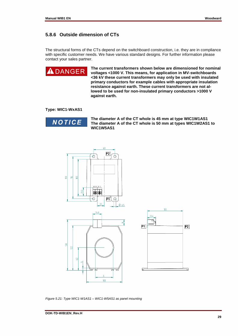
5.8.6 Outside dimension of CTs
The structural forms of the CTs depend on the switchboard construction, i.e. they are in compliance with specific customer needs. We have various standard designs. For further information please contact your sales partner.
The current transformers shown below are dimensioned for nominal voltages <1000 V. This means, for application in MV-switchboards <36 kV these current transformers may only be used with insulated primary conductors for example cables with appropriate insulation resistance against earth. These current transformers are not al-lowed to be used for non-insulated primary conductors >1000 V against earth.
Type: WIC1-WxAS1
The diameter A of the CT whole is 45 mm at type WIC1W1AS1 The diameter A of the CT whole is 50 mm at types WIC1W2AS1 to WIC1W5AS1
Figure 5.21: Type WIC1-W1AS1 – WIC1-W5AS1 as panel mounting
Woodward Manual WIB1 EN
30 DOK-TD-WIB1EN_Rev.H
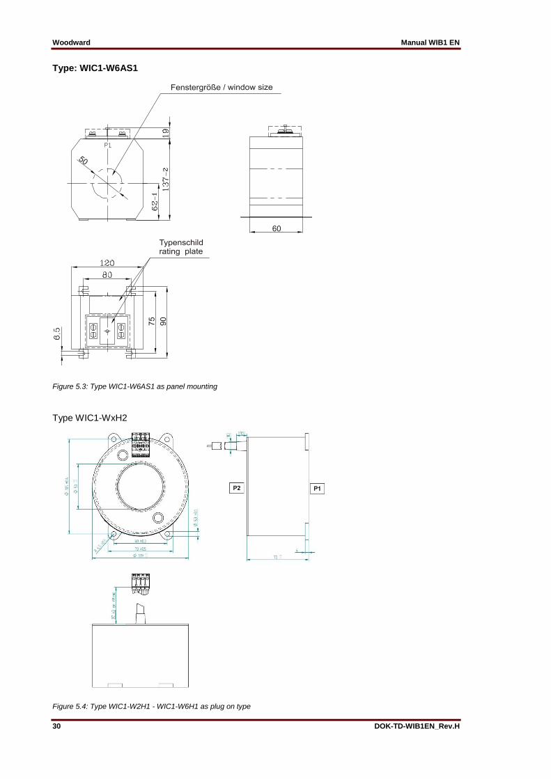
Type: WIC1-W6AS1
Figure 5.3: Type WIC1-W6AS1 as panel mounting
Type WIC1-WxH2
Figure 5.4: Type WIC1-W2H1 - WIC1-W6H1 as plug on type

Manual WIB1 EN Woodward
DOK-TD-WIB1EN_Rev.H 31
5.9 Characteristics and times
5.9.1 Characteristic curves
Figure 5.2: Normal Inverse
Figure 5.3: Very Inverse
*Multiples of pick up setting = Is * I>
For inverse characteristics please note that the factor ‘a’ is valid from 0.05 to 1 in WIB1 relay Please note that the time characteristics used in earth path is
limited to 100ms
1 2 3 4 5 6 7 8 910 20
Multiples of pick up setting *
0.1
1
10
100
1000
t[s]
a =
0.05
0.1
0.2
0.3
0.40.50.6
0.81.0
10.0
1.4
2.0
3.0
4.0
6.0
8.0
1 2 3 4 5 6 7 8 910 20
Multiples of pick up setting *
0.1
1
10
100
1000
t[s]a =
0.05
0.1
0.2
0.3
0.40.50.6
0.81.0
10.0
1.4
2.0
3.0
4.0
6.0
8.0

Woodward Manual WIB1 EN
32 DOK-TD-WIB1EN_Rev.H
Figure 5.4: Extremely Inverse
** The starting point of the characteristic should be in the area of the rated CT cur-rent , e. g. W2 = 16 – 30 A (Is) and the over current parameter I> should not set higher than 1.8 x Is. If over the parameter I> the starting point is set higher, then the relay cut the characteristics at 20 x upper rated current.
*Multiples of pick up setting = Is * I> For inverse characteristics please note that the factor ‘a’ is valid from 0.05 to 1 in WIB1 relay
Figure 5.5: Definite Time
Please note that the time characteristics used in earth path is limited to 100ms
1 2 3 4 5 6 7 8 910 20
Multiples of pick up setting *
0.01
0.1
1
10
100
1000
10000
t[s]
a =
0.050.05 0.10.1 0.2
0.30.40.50.60.81.0
10.0
1.4
2.0
3.04.0
6.08.0
1 10
Multiples of pick up setting *
0.01
0.1
1
10
100
t[s]
I>I>
tI>tI>
I>>I>>
tI>>tI>>
2.52.5
300300
0.040.04
0.90.9 202033
0.040.04
0.90.9I>I>
tI>tI>
I>>I>>
tI>>tI>>
2.52.5
300300
0.040.04
1.01.0 202033
0.040.04
0.90.9

Manual WIB1 EN Woodward
DOK-TD-WIB1EN_Rev.H 33
5.9.2 Calculation formula for IMT characteristics Normal Inverse:
𝑡 =0.14
(𝐼
𝐼𝑆 × 𝐼>)
0.02
− 1
∙ 𝑎[𝑠]
Very Inverse:
𝑡 =13.5
(𝐼
𝐼𝑆 × 𝐼>) − 1
∙ 𝑎[𝑠]
Extremely Inverse:
𝑡 =80
(𝐼
𝐼𝑆 × 𝐼>)
2
− 1
∙ 𝑎[𝑠]

Woodward Manual WIB1 EN
34 DOK-TD-WIB1EN_Rev.H
5.9.3 Trip coil output Trip coil output can be used with different type of trip coils Trip energy: E ≥0.1 Ws Voltage: ≥24 V DC Recommended minimum trip coil resistance: 4.3 Ohm at +20°C
5.9.4 Flag Indicators WI1-SZ4 Technical Data Coil: 24V DC ±10% - can be set electrically - can be reset mechanically Connector assignment Coil connection Core color mm² Function black 0.25 Gnd/Set black 0.25 Gnd/Set Cable connection length: 1 m WI1-SZ5: Technical Data Coil: 24V DC ± 10% Contact rating 230V AC/3 A 230V DC/0.12 A 115V DC/0.2 A 24V DC/2 A
Flag indicator with two potential free contacts
can be set and reset electrically
can be reset mechanically Connector assignment: Coil connection Core color mm² Function brown 0.25 (-) Gnd violet 0.25 (+) Set orange 0.25 (+) Reset changeover contact 1 white 0.50 NO contact yellow 0.50 changeover contact green 0.50 NC contact changeover contact 2 black 0.50 NO contact blue 0.50 changeover contact red 0.50 NC contact Cable connection length: 1 m

Manual WIB1 EN Woodward
DOK-TD-WIB1EN_Rev.H 35
5.10 Description of application
5.10.1 Foreword
As CT-powered protection relay the WIB1 is mainly used in MV switchboards with circuit breakers, protecting distribution transformers in local and industrial networks. Due to its small size the WIC1 is very well suited for the use in compact switchboards.
Figure 5.8: Basic circuit diagram of a standard switchboard with 2 feeders, circuit breaker and 1 outgoing transformer panel
Figure 5.9: Basic circuit diagram of a standard switchboard with 2 feeder, load break switch, fuse and 1 outgoing transform-er panel

Woodward Manual WIB1 EN
36 DOK-TD-WIB1EN_Rev.H
The ability of the protection system WIB1 to adapt to different primary currents makes it possible
that it is used for all standard rated transformer loads and the different MV operational voltages.
Manual WIB1 EN Woodward
DOK-TD-WIB1EN_Rev.H 37
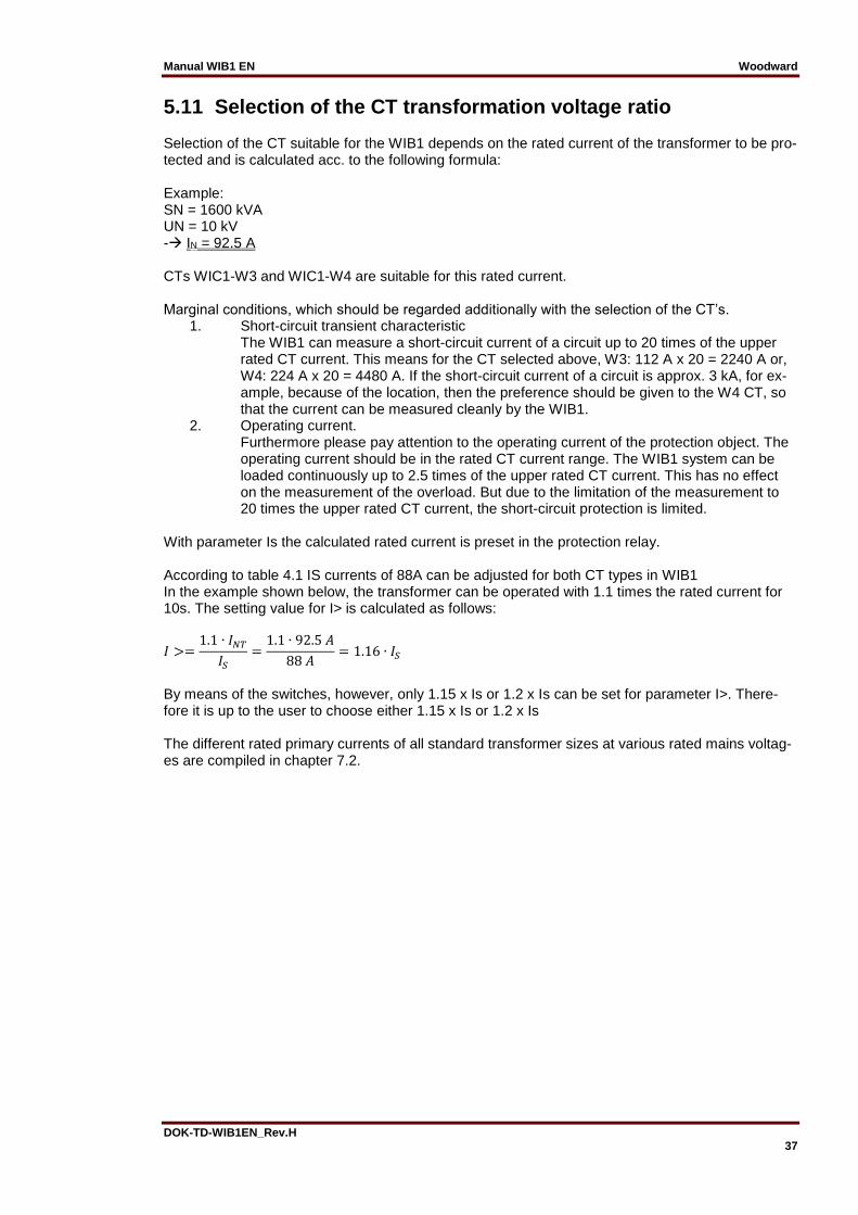
5.11 Selection of the CT transformation voltage ratio Selection of the CT suitable for the WIB1 depends on the rated current of the transformer to be pro-tected and is calculated acc. to the following formula: Example: SN = 1600 kVA UN = 10 kV - IN = 92.5 A CTs WIC1-W3 and WIC1-W4 are suitable for this rated current. Marginal conditions, which should be regarded additionally with the selection of the CT’s.
1. Short-circuit transient characteristic The WIB1 can measure a short-circuit current of a circuit up to 20 times of the upper rated CT current. This means for the CT selected above, W3: 112 A x 20 = 2240 A or, W4: 224 A x 20 = 4480 A. If the short-circuit current of a circuit is approx. 3 kA, for ex-ample, because of the location, then the preference should be given to the W4 CT, so that the current can be measured cleanly by the WIB1.
2. Operating current. Furthermore please pay attention to the operating current of the protection object. The operating current should be in the rated CT current range. The WIB1 system can be loaded continuously up to 2.5 times of the upper rated CT current. This has no effect on the measurement of the overload. But due to the limitation of the measurement to 20 times the upper rated CT current, the short-circuit protection is limited.
With parameter Is the calculated rated current is preset in the protection relay. According to table 4.1 IS currents of 88A can be adjusted for both CT types in WIB1 In the example shown below, the transformer can be operated with 1.1 times the rated current for 10s. The setting value for I> is calculated as follows:
𝐼 >=1.1 ∙ 𝐼𝑁𝑇
𝐼𝑆
=1.1 ∙ 92.5 𝐴
88 𝐴= 1.16 ∙ 𝐼𝑆
By means of the switches, however, only 1.15 x Is or 1.2 x Is can be set for parameter I>. There-fore it is up to the user to choose either 1.15 x Is or 1.2 x Is The different rated primary currents of all standard transformer sizes at various rated mains voltag-es are compiled in chapter 7.2.

Woodward Manual WIB1 EN
38 DOK-TD-WIB1EN_Rev.H
5.12 Adjustment instruction for inverse characteristic In the introduction phase of the WIB1 it came to understanding problems during the adjustment of the protection relay, in particular when using inverse characteristics. In the following now the con-nections are for this described. Notion definition: IS = Setting value of the load current With the parameter Is the operating current of the protected equipment is set. Due to the applica-tion of wide range CT’s the use of only one CT for a wide primary current range is applicable. All further setting parameter are related to the parameter Is. I> = Pick up value of the overcurrent element / Starting point of an overcurrent characteristic In case of a Definite Time characteristic this parameter sets the threshold value of the overcurrent element. In case of an Inverse characteristic this parameter sets the starting point of a characteristic. Exceed the measured current the factor Is x I> the WIB1 will pick up. tI> = Delay time of the overcurrent element by use of DEFT In case of a Definite Time characteristic this parameter sets the trip delay of the WIB1 after a pick up by I>. The relay will trip, if the threshold I> is still exceeded when the delay timer tI> has expired. a = Time multiplier of the characteristic by the use of INV In case of an Inverse characteristic, the trip delay is calculated based on the measured current and the chosen characteristic using the time multiplier “a”. The relay will trip, if the threshold I> is still exceeded when the delay given by the characteristic has expired. I>> = Pick up value of the short circuit element (only WIB12FE and WIB12PE) With this parameter the threshold value of the short current element is set. Exceed the measured current the factor Is x I>> the WIB1 will pick up. tI>> = Tripping time of the short circuit element (only WIB12FE and WIB12PE) This parameter sets the trip delay of the WIB1 after a pick up by I>>. The relay will trip, if the threshold I>> is still exceeded when the delay timer tI>> has expired.
IBLOCK = Pick up value of the blocking function (only WIB12PEB)
With this parameter the pick-up value of the blocking function is set. Exceed the measured current the factor Is x IBLOCK the tripping of the WIB12PEB is blocked.

Manual WIB1 EN Woodward
DOK-TD-WIB1EN_Rev.H 39
IE> = Pick up value of the earth overcurrent element / Starting point of an earth overcurrent characteristic In case of a Definite Time characteristic this parameter sets the threshold value of the earth over-current element. In case of an Inverse characteristic this parameter sets the starting point of a characteristic. Exceed the measured current the factor Is x IE> the WIB1 will pick up. tIE> = Delay time of the earth overcurrent element by use of DEFT In case of a Definite Time characteristic this parameter sets the trip delay of the WIB1 after a pick up by IE>. The relay will trip, if the threshold IE> is still exceeded when the delay timer tIE> has ex-pired. a = Time multiplier of the earth characteristic by the use of INV In case of an Inverse characteristic, the trip delay is calculated based on the measured current and the chosen characteristic using the time multiplier “a”. The relay will trip, if the threshold IE> is still exceeded when the delay given by the characteristic has expired. IE>> = Pick up value of the earth short circuit element With this parameter the threshold value of the earth short circuit element is set. Exceed the measured current the factor Is x IE>> the WIB1 will pick up. tI>> = Tripping time of the earth short circuit element This parameter sets the trip delay of the WIB1 after a pick up by IE>>. The relay will trip, if the threshold IE>> is still exceeded when the delay timer tIE>> has expired. For WIB1 this time is set fix to 100 ms.

Woodward Manual WIB1 EN
40 DOK-TD-WIB1EN_Rev.H
Estimation of the tripping time at inverse characteristics The estimation of the tripping time by the use of an inverse characteristic will be explained at the following example. Boundary condition: Operating current of the load (Is) 72 A Selected CT ratio WIB1-W4, 64 A – 120 A Characteristic Normal Inverse N-INV Starting point of the characteristic I> x Is Over current (I>): 1.4 Factor „a“ (tI>) 0.2 Short current (I>>) 1 kA Delay time for I>> 100 ms Primary test current value 150 A Setting of the WIB1: Is = 72 A I> = 1.4 „a“ (tI>) = 0.2 I>> = 14 (1 kA/72 A = 13.88) tI>> = 0.1 s Estimation of the tripping time from the characteristic curve Starting point of the curve = 1.4 x 72 A = 100.8 A, this correspond to = 1 x I/Is x I>. Primary testing current = 150 A, here for a factor as follows is calculated I/Is x I> = 150 A/100.8 A = 1.488
*Multiples of pick up setting =
From the curve a tripping time of 3.5 s is estimated.
For inverse characteristics please note that the factor ‘a’ is valid from 0.05 to 1 in WIB1 relay
1 2 3 4 5 6 7 8 910 20
Multiples of pick up setting *
0.1
1
10
100
1000
t[s]
a =
0.05
0.1
0.2
0.3
0.40.50.6
0.81.0
10.0
1.4
2.0
3.0
4.0
6.0
8.0
1.488
3.5
Manual WIB1 EN Woodward
DOK-TD-WIB1EN_Rev.H 41
6. Commissioning and Maintenance The following information can only be used for commissioning and maintenance of WIB12PE version as a secondary test method. The WIB12FE can only tested with primary test method.
6.1.1 Important note
Putting into operation and the relevant tests should only be carried out by skilled personnel. We do not accept any liability for damage caused by improper handling of the protection system, or of the primary side of the equipment. Pay attention to check that over the primary circuit no second current flow way is possible. (Grounding of the feeder).
6.2 Accessories for commissioning work For commissioning of the protection system the following accessories should be available:
Secondary testing system (see chapter 5.3ff)
Screwdriver; cross slot type, size 1; 3mm slot
Setting parameters
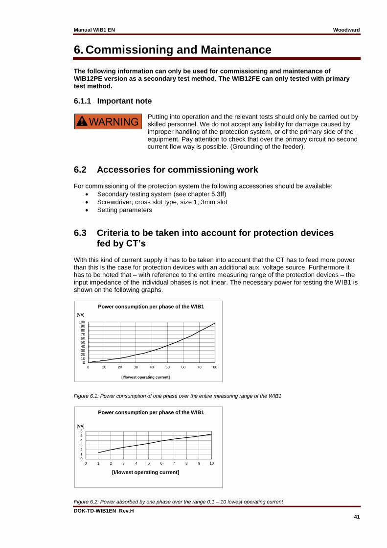
6.3 Criteria to be taken into account for protection devices fed by CT’s With this kind of current supply it has to be taken into account that the CT has to feed more power than this is the case for protection devices with an additional aux. voltage source. Furthermore it has to be noted that – with reference to the entire measuring range of the protection devices – the input impedance of the individual phases is not linear. The necessary power for testing the WIB1 is shown on the following graphs.
Figure 6.1: Power consumption of one phase over the entire measuring range of the WIB1
Figure 6.2: Power absorbed by one phase over the range 0.1 – 10 lowest operating current
0102030405060708090
100
0 10 20 30 40 50 60 70 80
[VA]
[I/lowest operating current]
Power consumption per phase of the WIB1
0
1
2
3
4
5
6
0 1 2 3 4 5 6 7 8 9 10
[VA]
[I/lowest operating current]
Power consumption per phase of the WIB1

Woodward Manual WIB1 EN
42 DOK-TD-WIB1EN_Rev.H
Lowest operating current = lower rated current x 0,9. The operating current is chosen by Is * I>. Current transformer type WIC1-W1xx: 7.2 A (Is = 8 A) WIC1-W2xx: 14.4 A (Is = 16 A) WIC1-W3xx: 28.8 A (Is = 32 A) WIC1-W4xx: 57.6 A (Is = 64 A) WIC1-W5xx: 115.2 A Is = 128 A) WIC1-W6xx: 230.4 A (Is = 256 A) Is = lowest rated current
6.4 Special features for the WIB1 test The WIB1 receives its supply energy out of the measuring circuit. Conditional on the circuit logic the WIB1 changes its measuring load in a cyclic way and that in a 1 kHz cycle. This can have an effect on the feeding source.
6.5 Selection of the secondary test system When selecting the secondary test system the following particulars should be taken into account.
Secondary test system to be used as power source.
Three phases for the earth current test, one phase for the phase current test (see chapter 5.8).
Sufficient output power for the switching points to be tested (see fig. 5.1 and 5.2).
The highest possible test current for testing via the test winding is at 22.4 amps. A test system with an output current up to 10 amps should be enough.
A timer for measuring the time 0 – 300 s. The time signal can be measured via the WIB1 outputs TC+/TC- or FI+/FI- or FE+/FE- as positive edge of a 24 V signal.
6.6 Checks during commissioning When putting into operation, the wiring and setting of the protection relay should be checked. Here the person doing the commissioning work is assisted by the integrated test windings of the WIB1 protection system, which are on the front of the relay. Hence any wiring jobs as well as actions in the cable connection area can be disregarded.
6.6.1 Wiring checks Wiring has to be checked with the circuitry shown in the diagram below.
1
2
S1
S2
WIC1
L1
3
gn/ye
C
D
1 ph ~ 1 A
Meas. winding
Test winding
1 A
50 A
0.26 A
L1
N
1-phase
Testing device
DI
TC+
TC- Timer
Figure 6.3: Connection of a single-phase testing device (phase L1) with CT WIC1-W2

Manual WIB1 EN Woodward
DOK-TD-WIB1EN_Rev.H 43
The testing current is fed via sockets L1, L2, L3 and N. The test winding is rated such that the fed current of 1A balances a primary current of 50 A (CT type WIC1-W2). The timer should be con-nected in parallel to the tripping coil or the flag indicator. If there is no tripping coil or flag indicator available when the test is performed, an input resistor should be connected to the timer. The re-sistance of a timer should be in the range of 20 Ohm up to1 kOhm. This prevents false measure-ments when tests are repeated in short intervals because the energy store cannot be discharged.
6.6.2 WIB1 adjustment The protection parameters are to be adjusted according to chapter 4 of this instruction. The set pa-rameters can be registered directly on the sticker affixed on the relay.
6.7 Functional Test There are two methods to carry out the tests: Primary test and secondary test. When the primary test method is used, the test current is impressed via the primary winding. When the secondary test method is used, the test current is impressed via the CD test winding. There are eight different standard CT types available for the WIB1.
CT Type Induced Current Primary Current Transformation Ratio
WIC1-WE1 1 A 25 A 25:1
WIC1-W1 1 A 25 25:1
WIC1-WE2 1 A 50 A 50:1
WIC1-W2 1 A 50 A 50:1
WIC1-W3 1 A 100 A 100:1
WIC1-W4 1 A 200 A 200:1
WIC1-W5 1 A 400 A 400:1
WIC1-W6 1 A 800 A 800:1
Woodward Manual WIB1 EN
44 DOK-TD-WIB1EN_Rev.H
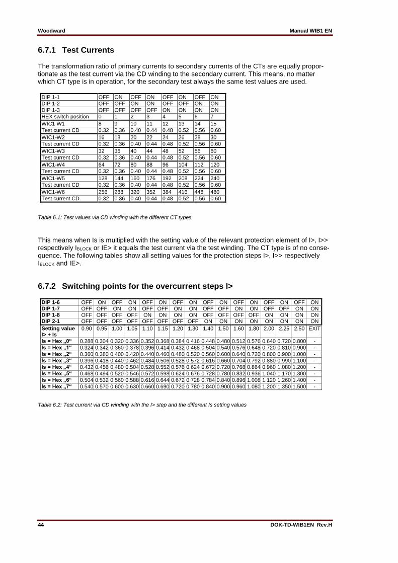
6.7.1 Test Currents The transformation ratio of primary currents to secondary currents of the CTs are equally propor-tionate as the test current via the CD winding to the secondary current. This means, no matter which CT type is in operation, for the secondary test always the same test values are used.
DIP 1-1 OFF ON OFF ON OFF ON OFF ON
DIP 1-2 OFF OFF ON ON OFF OFF ON ON
DIP 1-3 OFF OFF OFF OFF ON ON ON ON
HEX switch position 0 1 2 3 4 5 6 7
WIC1-W1 8 9 10 11 12 13 14 15
Test current CD 0.32 0.36 0.40 0.44 0.48 0.52 0.56 0.60
WIC1-W2 16 18 20 22 24 26 28 30
Test current CD 0.32 0.36 0.40 0.44 0.48 0.52 0.56 0.60
WIC1-W3 32 36 40 44 48 52 56 60
Test current CD 0.32 0.36 0.40 0.44 0.48 0.52 0.56 0.60
WIC1-W4 64 72 80 88 96 104 112 120
Test current CD 0.32 0.36 0.40 0.44 0.48 0.52 0.56 0.60
WIC1-W5 128 144 160 176 192 208 224 240
Test current CD 0.32 0.36 0.40 0.44 0.48 0.52 0.56 0.60
WIC1-W6 256 288 320 352 384 416 448 480
Test current CD 0.32 0.36 0.40 0.44 0.48 0.52 0.56 0.60
Table 6.1: Test values via CD winding with the different CT types
This means when Is is multiplied with the setting value of the relevant protection element of I>, I>> respectively IBLOCK or IE> it equals the test current via the test winding. The CT type is of no conse-quence. The following tables show all setting values for the protection steps I>, I>> respectively IBLOCK and IE>.
6.7.2 Switching points for the overcurrent steps I>
DIP 1-6 OFF ON OFF ON OFF ON OFF ON OFF ON OFF ON OFF ON OFF ON DIP 1-7 OFF OFF ON ON OFF OFF ON ON OFF OFF ON ON OFF OFF ON ON DIP 1-8 OFF OFF OFF OFF ON ON ON ON OFF OFF OFF OFF ON ON ON ON DIP 2-1 OFF OFF OFF OFF OFF OFF OFF OFF ON ON ON ON ON ON ON ON
Setting value I> + Is
0.90 0.95 1.00 1.05 1.10 1.15 1.20 1.30 1.40 1.50 1.60 1.80 2.00 2.25 2.50 EXIT
Is = Hex „0“ 0.288 0.304 0.320 0.336 0.352 0.368 0.384 0.416 0.448 0.480 0.512 0.576 0.640 0.720 0.800 -
Is = Hex „1“ 0.324 0.342 0.360 0.378 0.396 0.414 0.432 0.468 0.504 0.540 0.576 0.648 0.720 0.810 0.900 -
Is = Hex „2“ 0.360 0.380 0.400 0.420 0.440 0.460 0.480 0.520 0.560 0.600 0.640 0.720 0.800 0.900 1.000 -
Is = Hex „3“ 0.396 0.418 0.440 0.462 0.484 0.506 0.528 0.572 0.616 0.660 0.704 0.792 0.880 0.990 1.100 -
Is = Hex „4“ 0.432 0.456 0.480 0.504 0.528 0.552 0.576 0.624 0.672 0.720 0.768 0.864 0.960 1.080 1.200 -
Is = Hex „5“ 0.468 0.494 0.520 0.546 0.572 0.598 0.624 0.676 0.728 0.780 0.832 0.936 1.040 1.170 1.300 -
Is = Hex „6“ 0.504 0.532 0.560 0.588 0.616 0.644 0.672 0.728 0.784 0.840 0.896 1.008 1.120 1.260 1.400 -
Is = Hex „7“ 0.540 0.570 0.600 0.630 0.660 0.690 0.720 0.780 0.840 0.900 0.960 1.080 1.200 1.350 1.500 -
Table 6.2: Test current via CD winding with the I> step and the different Is setting values

Manual WIB1 EN Woodward
DOK-TD-WIB1EN_Rev.H 45
6.7.3 Switching points for the short-circuit steps I>> (only WIB12FE and WIB12PE)
DIP 2-5 OFF ON OFF ON OFF ON OFF ON OFF ON OFF ON OFF ON OFF ON
DIP 2-6 OFF OFF ON ON OFF OFF ON ON OFF OFF ON ON OFF OFF ON ON
DIP 2-7 OFF OFF OFF OFF ON ON ON ON OFF OFF OFF OFF ON ON ON ON
DIP 2-8 OFF OFF OFF OFF OFF OFF OFF OFF ON ON ON ON ON ON ON ON
Setting value I>> x Is
1 1.5 2 3 4 5 6 7 8 9 10 12 14 16 18 20
Is = Hex „0“ 0.32 0.48 0.64 0.96 1.28 1.60 1.92 2.24 2.56 2.88 3.20 3.84 4.48 5.12 5.76 6.40
Is = Hex „1“ 0.36 0.54 0.72 1.08 1.44 1.80 2.16 2.52 2.88 3.24 3.60 4.32 5.04 5.76 6.48 7.20
Is = Hex „2“ 0.40 0.60 0.80 1.20 1.60 2.00 2.40 2.80 3.20 3.60 4.00 4.80 5.60 6.40 7.20 8.00
Is = Hex „3“ 0.44 0.66 0.88 1.32 1.76 2.20 2.64 3.08 3.52 3.96 4.40 5.28 6.16 7.04 7.92 8.80
Is = Hex „4“ 0.48 0.72 0.96 1.44 1.92 2.40 2.88 3.36 3.84 4.32 4.80 5.76 6.72 7.68 8.64 9.60
Is = Hex „5“ 0.52 0.78 1.04 1.56 2.08 2.60 3.12 3.64 4.16 4.68 5.20 6.24 7.28 8.32 9.36 10.40
Is = Hex „6“ 0.56 0.84 1.12 1.68 2.24 2.80 3.36 3.92 4.48 5.04 5.60 6.72 7.84 8.96 10.08 11.20
Is = Hex „7“ 0.60 0.90 1.20 1.80 2.40 3.00 3.60 4.20 4.80 5.40 6.00 7.20 8.40 9.60 10.80 12.00
Is = Hex „8“ 0.64 0.96 1.28 1.92 2.56 3.20 3.84 4.48 5.12 5.76 6.40 7.68 8.96 10.24 11.52 12.80
Is = Hex „9“ 0.68 1.02 1.36 2.04 2.72 3.40 4.08 4.76 5.44 6.12 6.80 8.16 9.52 10.88 12.24 13.60
Is = Hex „A“ 0.72 1.08 1.44 2.16 2.88 3.60 4.32 5.04 5.76 6.48 7.20 8.64 10.08 11.52 12.96 14.40
Is = Hex „B“ 0.80 1.20 1.60 2.40 3.20 4.00 4.80 5.60 6.40 7.20 8.00 9.60 11.20 12.80 14.40 16.00
Is = Hex „C“ 0.88 1.32 1.76 2.64 3.52 4.40 5.28 6.16 7.04 7.92 8.80 10.56 12.32 14.08 15.84 17.60
Is = Hex „D“ 0.96 1.44 1.92 2.88 3.84 4.80 5.76 6.72 7.68 8.64 9.60 11.52 13.44 15.36 17.28 19.20
Is = Hex „E“ 1.04 1.56 2.08 3.12 4.16 5.20 6.24 7.28 8.32 9.36 10.40 12.48 14.56 16.64 18.72 20.80
Is = Hex „F“ 1.12 1.68 2.24 3.36 4.48 5.60 6.72 7.84 8.96 10.08 11.20 13.44 15.68 17.92 20.16 22.40
Table 6.3: Test current via CD winding with the I>> step and the different Is setting values
6.7.4 Switching points for the blocking function steps IBLOCK (only WIB12PEB)
DIP 2-5 OFF ON OFF ON OFF ON OFF ON OFF ON OFF ON OFF ON OFF ON
DIP 2-6 OFF OFF ON ON OFF OFF ON ON OFF OFF ON ON OFF OFF ON ON
DIP 2-7 OFF OFF OFF OFF ON ON ON ON OFF OFF OFF OFF ON ON ON ON
DIP 2-8 OFF OFF OFF OFF OFF OFF OFF OFF ON ON ON ON ON ON ON ON
Setting value
IBLOCK x Is
1 2 3 4 5 6 7 8 9 10 12 14 16 18 20 EXIT
Is = Hex „0“ 0.32 0.64 0.96 1.28 1.60 1.92 2.24 2.56 2.88 3.20 3.84 4.48 5.12 5.76 6.40 -
Is = Hex „1“ 0.36 0.72 1.08 1.44 1.80 2.16 2.52 2.88 3.24 3.60 4.32 5.04 5.76 6.48 7.20 -
Is = Hex „2“ 0.40 0.80 1.20 1.60 2.00 2.40 2.80 3.20 3.60 4.00 4.80 5.60 6.40 7.20 8.00 -
Is = Hex „3“ 0.44 0.88 1.32 1.76 2.20 2.64 3.08 3.52 3.96 4.40 5.28 6.16 7.04 7.92 8.80 -
Is = Hex „4“ 0.48 0.96 1.44 1.92 2.40 2.88 3.36 3.84 4.32 4.80 5.76 6.72 7.68 8.64 9.60 -
Is = Hex „5“ 0.52 1.04 1.56 2.08 2.60 3.12 3.64 4.16 4.68 5.20 6.24 7.28 8.32 9.36 10.40 -
Is = Hex „6“ 0.56 1.12 1.68 2.24 2.80 3.36 3.92 4.48 5.04 5.60 6.72 7.84 8.96 10.08 11.20 -
Is = Hex „7“ 0.60 1.20 1.80 2.40 3.00 3.60 4.20 4.80 5.40 6.00 7.20 8.40 9.60 10.80 12.00 -
Is = Hex „8“ 0.64 1.28 1.92 2.56 3.20 3.84 4.48 5.12 5.76 6.40 7.68 8.96 10.24 11.52 12.80 -
Is = Hex „9“ 0.68 1.36 2.04 2.72 3.40 4.08 4.76 5.44 6.12 6.80 8.16 9.52 10.88 12.24 13.60 -
Is = Hex „A“ 0.72 1.44 2.16 2.88 3.60 4.32 5.04 5.76 6.48 7.20 8.64 10.08 11.52 12.96 14.40 -
Is = Hex „B“ 0.80 1.60 2.40 3.20 4.00 4.80 5.60 6.40 7.20 8.00 9.60 11.20 12.80 14.40 16.00 -
Is = Hex „C“ 0.88 1.76 2.64 3.52 4.40 5.28 6.16 7.04 7.92 8.80 10.56 12.32 14.08 15.84 17.60 -
Is = Hex „D“ 0.96 1.92 2.88 3.84 4.80 5.76 6.72 7.68 8.64 9.60 11.52 13.44 15.36 17.28 19.20 -
Is = Hex „E“ 1.04 2.08 3.12 4.16 5.20 6.24 7.28 8.32 9.36 10.40 12.48 14.56 16.64 18.72 20.80 -
Is = Hex „F“ 1.12 2.24 3.36 4.48 5.60 6.72 7.84 8.96 10.08 11.20 13.44 15.68 17.92 20.16 22.40 -
Table 6.4: Test current via CD winding with the IBLOCK step and the different Is setting values

Woodward Manual WIB1 EN
46 DOK-TD-WIB1EN_Rev.H
6.8 Special features for earth current tests Functional description: In the WIB1 the earth current is calculated and cannot be measured. It is established from the ge-ometrical amount of the three phase current values, more or less a numerical Holmgreen. If, for in-stant, a single-phase test current is impressed, the measuring value (tripping value) in the earth current path equals the current in the tested phase. If, with a phase shift of 120° a three-phase test current is impressed, the measuring value in the earth current path equals zero. Requirement on the test system: The WIB1 is powered by the instrument transformer. In order to guarantee reliable tripping a mini-mal current of 0.9 x lowest nominal CT current (0.9 x lowest I> setting) has to flow in one of the phases. If the setting of the earth current IE> is lower than the smallest possible switching point for the phase current, then the switching point for earth current tripping can only be tested by a three-phase power source. In case the set switching point for earth current is higher than the smallest possible switching point for overcurrent tripping (Is x I>), then the test can be performed with a sin-gle-phase power source.
6.8.1 Switching points for the earth current step IE>
DIP 3-7 OFF ON OFF ON OFF ON OFF ON OFF ON OFF ON OFF ON OFF ON
DIP 3-8 OFF OFF ON ON OFF OFF ON ON OFF OFF ON ON OFF OFF ON ON
DIP 4-1 OFF OFF OFF OFF ON ON ON ON OFF OFF OFF OFF ON ON ON ON
DIP 4-2 OFF OFF OFF OFF OFF OFF OFF OFF ON ON ON ON ON ON ON ON
Einstellwert IE> x Is
0.2* 0.3* 0.4* 0.5* 0.6* 0.7* 0.8* 0.9 1 1.2 1.4 1.6 1.8 2.0 2.5 EXIT
Is = Hex „0“ 0,064 0,096 0,128 0,160 0,192 0,224 0,256 0,288 0,320 0,384 0,448 0,512 0,576 0,640 0,800 -
Is = Hex „1“ 0,072 0,108 0,144 0,180 0,216 0,252 0,288 0,324 0,360 0,432 0,504 0,576 0,648 0,720 0,900 -
Is = Hex „2“ 0,080 0,120 0,160 0,200 0,240 0,280 0,320 0,360 0,400 0,480 0,560 0,640 0,720 0,800 1,000 -
Is = Hex „3“ 0,088 0,132 0,176 0,220 0,264 0,308 0,352 0,396 0,440 0,528 0,616 0,704 0,792 0,880 1,100 -
Is = Hex „4“ 0,096 0,144 0,192 0,240 0,288 0,336 0,384 0,432 0,480 0,576 0,672 0,768 0,864 0,960 1,200 -
Is = Hex „5“ 0,104 0,156 0,208 0,260 0,312 0,364 0,416 0,468 0,520 0,624 0,728 0,832 0,936 1,040 1,300 -
Is = Hex „6“ 0,112 0,168 0,224 0,280 0,336 0,392 0,448 0,504 0,560 0,672 0,784 0,896 1,008 1,120 1,400 -
Is = Hex „7“ 0,120 0,180 0,240 0,300 0,360 0,420 0,480 0,540 0,600 0,720 0,840 0,960 1,080 1,200 1,500 -
Table 6.4: Test current via the CD winding with the IE> step and the different Is setting values
* When the earth current setting is <0.9 x Is a three-phase test system has to be used for correct testing. With a single-phase test the trip is only triggered from 0.9 x Is on.
6.8.2 Switching points for the earth current short-circuit step IE>>
DIP 2-5 OFF ON OFF ON OFF ON OFF ON
DIP 2-6 OFF OFF ON ON OFF OFF ON ON
DIP 2-7 OFF OFF OFF OFF ON ON ON ON
DIP 2-8 OFF OFF OFF OFF OFF OFF OFF ON
Setting value IE>> x Is
1 2 3 4 5 6 7 EXIT
Is = Hex „0“ 0.32 0.64 0.96 1.28 1.60 1.92 2.24 -
Is = Hex „1“ 0.36 0.72 1.08 1.44 1.80 2.16 2.52 -
Is = Hex „2“ 0.40 0.80 1.20 1.60 2.00 2.40 2.80 -
Is = Hex „3“ 0.44 0.88 1.32 1.76 2.20 2.64 3.08 -
Is = Hex „4“ 0.48 0.96 1.44 1.92 2.40 2.88 3.36 -
Is = Hex „5“ 0.52 1.04 1.56 2.08 2.60 3.12 3.64 -
Is = Hex „6“ 0.56 1.12 1.68 2.24 2.80 3.36 3.92 -
Is = Hex „7“ 0.60 1.20 1.80 2.40 3.00 3.60 4.20 -
Table 6.5: Test current via CD winding with the I>> step and the different Is setting values

Manual WIB1 EN Woodward
DOK-TD-WIB1EN_Rev.H 47
6.9 Test procedure by way of example When testing the WIB1, the tests of the individual equipment should be carried out from the highest setting value to the smallest one. The order ought to be: 1) Short circuit I>> 2) Time delay tI>> 3) Over current I> 4) Time delay tI> 5) Earth current IE>> high set 6) Earth current IE> low set 7 Time delay tIE> In here the complete test can only be exemplified with free defined switching points. For the test a single-phase power source has to be used. General setting: Is = Nominal Current of the equipment conditional on the used CT, on which all switching points of I>>, I>, IE>> and IE> are based. CHAR = either Definite Time or Inverse Characteristic – dependent on the requirement. The device will be adjusted by way of the DIP switches. Here the test will be performed with the following settings: Is = 1.15 I_Char = Definite Time I> = 1.05 x Is tI> = 1.00 s I>> = 4.00 x Is tI>> = 0.20 s IE_Char = Definite Time IE> = 0.9 x Is tIE> = 0.2 s IE>> = 2.00 x Is Test step 1): Test of the short circuit step I>>. For this the following parameters have to be blocked: I> = EXIT tI>> = EXIT IE> = EXIT IE>> = EXIT The single-phase test current has to be increased slowly until the relay or the LED indicator trips. The tripping current can be controlled by the fault value memory. Since the WIB1 is operating phase-selectively, each phase can be tested separately. Test step 2): Test of the trip delay tI>> Settings: I>> = 4.00 x Is tI>> = e.g. 0.10 s During the single-phase test the switching point of I>> setting has to be rapidly changed from 80% to 120%. The tripping time is ascertained by an external timer. The jump is to be used as start im-pulse. The trip impulse coming from the flag indicator or the tripping coil serves as stop signal. If a 80% or 120% jump is not possible with the test instrument, then the jump should be from 0 to 120% of the I>>. Dependent on the test parameter for I>> and the set tripping time for tI>>, the charging and boot time needed by the relay has to be deducted. See chapter 4.1.2 Phase Over-Current Time Protection.

Woodward Manual WIB1 EN
48 DOK-TD-WIB1EN_Rev.H
Test step 3): Test of the over-current step I>: Settings: I> = 1.05 x Is tI> = EXIT I>> = 4.00 x Is tI>> = 0.10 s IE> = EXIT tIE> = 0.2 s IE>> = EXIT Test to be carried out as described under “Test step 1”. Test step 4): Test of the trip delay tI> Settings: I> = 1.05 x Is tI> = 1.00 s Test to be carried out as described under „Test step 2“. Test step 5): Test of the earth current step IE> Settings: I> = EXIT tI> = 1.00 s I>> = 4.00 x Is tI>> = 0.10 s IE> = EXIT IE>> = 2 x Is Test to be carried out as described under „Test step 2“. This protection function has only an instan-taneous tripping delay time. Test step 6): Test of the earth current step IE> Settings: I> = EXIT tI> = 1.00 s I>> = 4.00 x Is tI>> = 0.10 s IE> = 0.9 x Is tIE> = EXIT IE>> = 2 x Is Test to be carried out as described under „Test step 1“. Test step 7: Test of the trip delay tIE> Settings: IE> = 0.9 x Is tIE> = 0.2 s Test to be carried out as described under „Test step 2“.
Tests on the earth current path can only be performed with a single-phase power source if the switching point for the IE> setting is >= 0.9 x Is. See chapter 5.8.

Manual WIB1 EN Woodward
DOK-TD-WIB1EN_Rev.H 49
6.10 Maintenance The entire protection system WIB1 is designed for a maintenance-free period of 25 years, hence there are no specific jobs necessary to be done during the operating life of the relays. Very often, a periodical check of the protective adjustments is required by the end user. Such checks are left to the choice of the user and can be carried out as described under chapter 6.2.
6.10.1 Faults Should, however, faults occur despite the special design of the protection system and the compre-hensive quality control, the possibility for fault clearance by the user is only limited. For possible faults and their clearance please see the following table:
Fault Cause of failure Remedy
Wrong measuring and trip-ping values
Test winding short-circuited Secondary side of test winding always to be operated openly (except when relays are test-ed)
Wrong measuring and trip-ping values
Earthing of a winding terminal of the measuring winding
No winding terminal of the measuring winding to be earthed! Earthing is done in-ternally and brought out at terminal PE
Low-energy tripping coil does not trip
Coil polarized with permanent magnet wrong connected to TC+ and TC-
Wiring to be checked
6.10.2 Repair work The WIB1 is a hermetically sealed relay and so it is not possible to do any repair work at your end. Due to the optimized cost structure, however, repair in our works is also not beneficial. During the warranty period the protection relay is exchanged by us free of charge, provided the failure was not caused by external influences. Should such a situation occur, please contact our local sales agent.

Woodward Manual WIB1 EN
50 DOK-TD-WIB1EN_Rev.H
7. Product Specific Features
7.1 Assignment of terminals
7.1.1 Assignment of terminals at WIB12PE and WIB12PEB The protection relay is equipped with 22 screw-type terminals
Terminal marking Description
230 V Remote trip input for auxiliary voltage 230 V AC
115 V Remote trip input for auxiliary voltage 115 V AC
N Remote trip input N (earth)
PE Centre earthing point WIC1
FI+ Flag indicator output for phase failure, +pole
FI- Flag indicator output for phase failure, -pole
TC+ Electric pulse output +pole
TC- Electric pulse output, -pole
FE+ Flag indicator output for earth failure, +pole
FE- Flag indicator output for earth failure, -pole
L1_S1 CT measuring winding connection L1
L2_S2 CT measuring winding connection L1
L2_S1 CT measuring winding connection L2
L2_S2 CT measuring winding connection L2
L3_S1 CT measuring winding connection L3
L3_S2 CT measuring winding connection L3
The terminals 230 V, 115 V, N and PE are provided as fixed terminals.
7.1.2 Assignment of terminals at WIB12FE The protection relay is equipped with 16 screw-type terminals
Terminal marking Description
230 V Remote trip input for auxiliary voltage 230 V AC
115 V Remote trip input for auxiliary voltage 115 V AC
N Remote trip input N (earth)
PE Centre earthing point WIC1
FI+ Flag indicator output for phase failure, +pole
FI- Flag indicator output for phase failure, -pole
TC+ Electric pulse output +pole
TC- Electric pulse output, -pole
FE+ Flag indicator output for earth failure, +pole
FE- Flag indicator output for earth failure, -pole
The terminals 230 V, 115 V, N and PE are provided as fixed terminals.
7.1.3 Earthing For earthing the WIB1 connection terminal PE is used.
The measuring winding (terminals S1and S2) of the CTs must not be earthed; otherwise the measurement results are distorted, ensuring in er-ratic behavior of the relay.

Manual WIB1 EN Woodward
DOK-TD-WIB1EN_Rev.H 51
7.2 Current transformer Listed CT ranges in relation to the transformer rated currents
3.00 3.30 4.20 5.50 6.00 6.60 10.00 11.00 12.00 13.80 15.00 15.50 17.50 20.00 21.00 22.00 24.00 U[kV]
50.00 9,62 8,75 WIC1-W1 75.00 14,43 13,12 10,31 7,87 7,22 100.00 19,25 17,50 13,75 10,50 9,62 8,75 125.00 24,06 21,87 17,18 13,12 12,03 10,93 7,22 160.00 28,87 26,24 20,62 15,75 14,43 13,12 8,66 7,87 7,22 200.00 34,99 27,49 20,99 19,25 17,50 11,55 10,50 9,62 8,37 7,70 7,45 250.00 34,37 26,24 24,06 21,87 14,43 13,12 12,03 10,46 9,62 9,31 8,25 7,22 315.00 33,07 30,31 27,56 18,19 16,53 15,16 13,18 12,12 11,73 10,39 9,09 8,66 8,27 7,58 400.00 38,49 34,99 23,09 20,99 19,25 16,73 15,40 14,90 13,20 11,55 11,00 10,50 9,62 500.00 28,87 26,24 24,06 20,92 19,25 18,62 16,50 14,43 13,75 13,12 12,03 630.00 36,37 33,07 30,31 26,36 24,25 23,47 20,78 18,19 17,32 16,53 15,16 800.00 38,49 33,47 30,79 29,80 26,39 23,09 21,99 20,99 19,25 1000.00 38,49 37,25 32,99 28,87 27,49 26,24 24,06 1250.00 36,08 34,37 32,80 30,07 1600.00 38,49 2000.00
3.00 3.30 4.20 5.50 6.00 6.60 10.00 11.00 12.00 13.80 15.00 15.50 17.50 20.00 21.00 22.00 24.00 U[kV]
50.00 WIC1-W2 75.00 14,43 100.00 19,25 17,50 125.00 24,06 21,87 17,18 160.00 30,79 27,99 21,99 16,80 15,40 200.00 38,49 34,99 27,49 20,99 19,25 17,50 250.00 48,11 43,74 34,37 26,24 24,06 21,87 14,43 315.00 60,62 55,11 43,30 33,07 30,31 27,56 18,19 16,53 15,16 400.00 69,98 54,99 41,99 38,49 34,99 23,09 20,99 19,25 16,73 15,40 14,90 500.00 68,73 52,49 48,11 43,74 28,87 26,24 24,06 20,92 19,25 18,62 16,50 14,43 630.00 66,13 60,62 55,11 36,37 33,07 30,31 26,36 24,25 23,47 20,78 18,19 17,32 16,53 15,16 800.00 76,98 69,98 46,19 41,99 38,49 33,47 30,79 29,80 26,39 23,09 21,99 20,99 19,25 1000.00 57,74 52,49 48,11 41,84 38,49 37,25 32,99 28,87 27,49 26,24 24,06 1250.00 72,17 65,61 60,14 52,30 48,11 46,56 41,24 36,08 34,37 32,80 30,07 1600.00 76,98 66,94 61,58 59,60 52,79 46,19 43,99 41,99 38,49 2000.00 76,98 74,50 65,98 57,74 54,99 52,49 48,11 2500.00 72,17 68,73 65,61 60,14 3150.00 82,67 75,78 S[kVA]
3.00 3.30 4.20 5.50 6.00 6.60 10.00 11.00 12.00 13.80 15.00 15.50 17.50 20.00 21.00 22.00 24.00 U[kV]
125.00 WIC1-W3 160.00 30,79 200.00 38,49 34,99 250.00 48,11 43,74 34,37 315.00 60,62 55,11 43,30 33,07 30,31 400.00 76,98 69,98 54,99 41,99 38,49 34,99 500.00 96,23 87,48 68,73 52,49 48,11 43,74 28,87 630.00 121,24 110,22 86,60 66,13 60,62 55,11 36,37 33,07 30,31 800.00 153,96 139,96 109,97 83,98 76,98 69,98 46,19 41,99 38,49 33,47 30,79 29,80 1000.00 137,46 104,97 96,23 87,48 57,74 52,49 48,11 41,84 38,49 37,25 32,99 28,87 1250.00 131,22 120,28 109,35 72,17 65,61 60,14 52,30 48,11 46,56 41,24 36,08 34,37 32,80 30,07 1600.00 153,96 139,96 92,38 83,98 76,98 66,94 61,58 59,60 52,79 46,19 43,99 41,99 38,49 2000.00 115,47 104,97 96,23 83,67 76,98 74,50 65,98 57,74 54,99 52,49 48,11 2500.00 144,34 131,22 120,28 104,59 96,23 93,12 82,48 72,17 68,73 65,61 60,14 3150.00 165,33 151,55 131,79 121,24 117,33 103,92 90,93 86,60 82,67 75,78 4000.00 153,96 148,99 131,97 115,47 109,97 104,97 96,23 S[kVA]
3.00 3.30 4.20 5.50 6.00 6.60 10.00 11.00 12.00 13.80 15.00 15.50 17.50 20.00 21.00 22.00 24.00 U[kV]
250.00 WIC1-W4 315.00 60,62 400.00 76,98 69,98 500.00 96,23 87,48 68,73 630.00 121,24 110,22 86,60 66,13 60,62 800.00 153,96 139,96 109,97 83,98 76,98 69,98 1000.00 192,45 174,95 137,46 104,97 96,23 87,48 57,74 1250.00 240,56 218,69 171,83 131,22 120,28 109,35 72,17 65,61 60,14 1600.00 307,92 279,93 219,94 167,96 153,96 139,96 92,38 83,98 76,98 66,94 61,58 59,60 2000.00 274,93 209,95 192,45 174,95 115,47 104,97 96,23 83,67 76,98 74,50 65,98 57,74 2500.00 240,56 218,69 144,34 131,22 120,28 104,59 96,23 93,12 82,48 72,17 68,73 65,61 60,14 3150.00 303,11 275,55 181,87 165,33 151,55 131,79 121,24 117,33 103,92 90,93 86,60 82,67 75,78 4000.00 230,94 209,95 192,45 167,35 153,96 148,99 131,97 115,47 109,97 104,97 96,23 S[kVA]
3.00 3.30 4.20 5.50 6.00 6.60 10.00 11.00 12.00 13.80 15.00 15.50 17.50 20.00 21.00 22.00 24.00 U[kV]
500.00 WIC1-W5 630.00 121,24 800.00 153,96 139,96 1000.00 192,45 174,95 137,46 1250.00 240,56 218,69 171,83 131,22 120,28 1600.00 307,92 279,93 219,94 167,96 153,96 139,96 2000.00 384,90 349,91 274,93 209,95 192,45 174,95 115,47 2500.00 481,13 437,39 343,66 262,43 240,56 218,69 144,34 131,22 120,28 3150.00 606,22 551,11 433,01 330,66 303,11 275,55 181,87 165,33 151,55 131,79 121,24 4000.00 549,86 419,89 384,90 349,91 230,94 209,95 192,45 167,35 153,96 148,99 131,97 115,47 5000,00 524,86 481,13 437,39 288,68 262,43 240,56 209,18 192,45 186,24 164,96 144,34 137,46 131,22 120,28 6300,00 606,22 551,11 363,73 330,66 303,11 263,57 242,49 234,66 207,85 181,87 173,21 165,33 151,55 S[kVA]

Woodward Manual WIB1 EN
52 DOK-TD-WIB1EN_Rev.H
3.00 3.30 4.20 5.50 6.00 6.60 10.00 11.00 12.00 13.80 15.00 15.50 17.50 20.00 21.00 22.00 24.00 U[kV]
1000.00 WIC1-W6 1250.00 240,56 1600.00 307,92 279,93 2000.00 384,90 349,91 274,93 2500.00 481,13 437,39 343,66 262,43 240,56 3000.00 606,22 551,11 433,01 330,66 303,11 275,55 4000.00 769,80 699,82 549,86 419,89 384,90 349,91 230,94 5000.00 962,25 874,77 687,32 524,86 481,13 437,39 288,68 262,43 240,56 6300.00 1212,44 1102,21 866,03 661,33 606,22 551,11 363,73 330,66 303,11 263,57 242,49 234,66 10000.00 1749,55 1374,64 1049,73 962,25 874,77 577,35 524,86 481,13 418,37 384,90 372,48 S[kVA]

Manual WIB1 EN Woodward
DOK-TD-WIB1EN_Rev.H 53
8. Annex
8.1 Dimensional drawing relay
Figure 8.1: Dimensional drawing
8.2 Dimensional drawing flag indicator
Figure 8.2: Flag indicator WI1-SZ4/WI1-SZ5

Woodward Manual WIB1 EN
54 DOK-TD-WIB1EN_Rev.H
8.3 Order form
Multi characteristic time over current relay WIB1 2 E
3-phase current measuring I>;I>> self powered – parameter setting via DIP switches
2
Connection mode - plug in screw terminals connectors for test winding Routine Safety Check with backup protection I>> (only WIB12PE)
– fixed screw terminal
P
F
With additional earth current supervision* IE> – standard 0.2 to 2.5 x IS (internal vector addition)
With blocking funktion (IBLOCK) (only WIB12PEB) B
The following device variants can be ordered:
WIB12PE
WIB12PEB
WIB12FE
Flag indicators WI1
Small type, front 34 x 23 mm, connection lead 1m
Small type, front 34 x 23 mm, connection lead 1m with bi-stable signal contact 230 V AC, 3 A
SZ4
SZ5
Accessories WIC1
PC adapter for RS232 serial port
PC adapter for USB port
Watchdog test unit
PC2
PC3
TU
Current transformer (1 piece) WIC1
8 – 28 A SVA 100 100-45 10P40 8 – 28 A SVA 100 100-45 5P40 16 – 56 A SVA 100-100-50 10P80 16 – 56 A SVA 100-100-50 5P80 32 – 112 A SVA 100-100-50 5P80 64 – 224 A SVA 100-100-50 5P80 128 – 448 A SVA 100-100-50 5P80 256 – 896 A GSA 120-60-50 5P80
W1AS1
WE1AS1
W2AS1
WE2AS1
W3AS1
W4AS1
W5AS1
W6AS1
Further designs e.g. supporting type, plug-on type etc. on request. Note: CT housing in accordance with the customer requirements.

Manual WIB1 EN Woodward
DOK-TD-WIB1EN_Rev.H 55
8.4 Commissioning form List of adjustments for WIB1 Project: Order No.: Functional group: Location: Component Identification: Relay Function: Date:
8.4.1 Parameter Setting WIB12FE and WIB12PE
Function
Unit
Default Setting
Actual Setting
CT Type Wx
Is Rated CT current e.g. W2 type of CT A 16
I_Char Trip characteristic for phase current DEFT
IE_Char Trip characteristic for earth current DEFT
I> Pickup value for DMT characteristic or start val-ue of the IMT characteristic
x Is 0.9
tI> Tripping time for DMT characteristic s 0.1
a Multiplier for IMT characteristic s --
I>> Pickup value for short-circuit element x Is 1
tI>> Tripping time for short-circuit element s 0.04
IE> Pickup value for earth fault element x Is 0.2
tIE> Tripping time for earth fault element s 0.1
IE>> Pickup value for the 2nd earth fault element x Is 1
8.4.2 Parameter Setting WIB12PEB
Function
Unit
Default Setting
Actual Setting
CT Type Wx
Is Rated CT current e.g. W2 type of CT A 16
I_Char Trip characteristic for phase current DEFT
IE_Char Trip characteristic for earth current DEFT
I> Pickup value for DMT characteristic or start val-ue of the IMT characteristic
x Is 0.9
tI> Tripping time for DMT characteristic s 0.1
a Multiplier for IMT characteristic s --
IBLOCK Pickup value for blocking function x Is 1
IE> Pickup value for earth fault element x Is 0.2
tIE> Tripping time for earth fault element s 0.1
IE>> Pickup value for the 2nd earth fault element x Is 1
Signature Checker: Signature customer:

Woodward Manual WIB1 EN
56 DOK-TD-WIB1EN_Rev.H
Woodward Kempen GmbH
Krefelder Weg 47 D – 47906 Kempen (Germany)
Postfach 10 07 55 (P.O.Box) D – 47884 Kempen (Germany)
Phone: +49 (0) 21 52 145 1
Internet
Homepage http://www.woodward.com
Sales
Tel.: +49 (0) 21 52 145 331 or +49 (0) 711 789 54 510
Fax: +49 (0) 21 52 145 354 or +49 (0) 711 789 54 101
e-mail: [email protected]
Service
Phone: +49 (0) 21 52 145 600 Telefax: +49 (0) 21 52 145 455
e-mail: [email protected]


![Poster Kempen Jimat Elektrik - devel.upm.edu.my1].pdf · Title: Poster Kempen Jimat Elektrik Created Date: 8/23/2013 9:47:56 AM](https://static.fdocuments.us/doc/165x107/5c966ff709d3f2650d8c4d80/poster-kempen-jimat-elektrik-develupmedumy-1pdf-title-poster-kempen.jpg)


