COMPOSITE MATERIALS Pultrusion Process Composite Manufacturing

Why composite materials?
Paradigm in Materials Science: “smaller is stronger”
In the current stage of technological development, the strongest materials that can be easily handled are manufactured in the form of small diameter fibers (< 200 µm).
The use of fibers in structural elements has the following limitations:
! - Punching! - Surface damage (abrasion, wear and chemical attack)! - Buckling! - Optimum orientation
These problems are overcome when the fibers are embedded in a continuum matrix. Composite materials were developed in parallel with the manufacturing of new fibers with high stiffness and strength.
Thus, the first reason to use composite materials is to take advantage of the outstanding mechanical properties of fibers.

Why composite materials?
Second reason: The dispersion of reinforcements (either fibers or particles) can improve the matrix properties (toughness of ceramics, high temperature mechanical properties of metals, conductivity of polymers), leading to new applications.
Third reason: Design of materials with optimized properties (e.g. specific stiffness or strength) or with tailored multifunctional properties for specific applications (i.e. non-magnetic hulls of minesweeper, isostatic platforms for satellites with null CTE, biocompatible prothesis, etc.)

Typology of composite materials
According to the matrix: polymer-matrix composites (PMC), metal-matrix composites (MMC) and ceramic-matrix composites (CMC). The latter also include carbon-carbon composites (CCC).
According to the reinforcement geometry: - Particle reinforced composites- Short-fiber reinforced composites- Long-fiber reinforced composites:
- Unidirectional and woven lamina- Multiaxial laminates (2D)- 3D preforms (weaving, knitting, braiding, stitching)
According to the origin: - Artificial (man-made)- Natural:
- wood: lignin/hemicellulose matrix reinforced with cellulose fibers- bone: hidroxi-apatite matrix reinforced with collagen fibers- crustacean shell: multilayer structure made up of alternative CO3Ca and protein layers.

Applications of composite materials
Composites industry was born with the development of high performance fibers. It has grown steadily during the last fifty years and composites are nowadays used in most engineering applications.

An example: composites in sports
Vaulting pole

An example: composites in sports
Tennis racket
(a) (b)

An example: composites in sports
Surfboard

Composite structures
Helicopter rotor blade

Reinforcement classification
Particles Whiskers & nanofibers Fibers:
! ! - Asbestos (mineral)- Natural:! - Cellulose (vegetal)
! - Collagen and silk (animal)
! ! ! ! ! Aramid! ! ! - Organic:! Polyethylene! ! ! ! ! Carbon
! - Synthetic! ! ! ! ! Glass! ! ! ! ! Ceramic!! SiC! ! ! - Inorganic:! ! ! Al2O3! ! ! ! !! ! ! ! ! Metallic !! steel, W, etc.

Fibrous mineral of chemical composition Mg3(Si2O5)(OH)4 easily obtained from serpentinite rocks which are common throughout the world. Asbestos fiber can reach several cm in length.
It was widely used mixed with cement because improved the tensile strength and provided better electrical insulation and resistance to fire and heat. It is currently banned from most applications because inhalation of asbestos fibers lead to lung cancer.
natural fibersAsbestos
Cellulose Polymeric fiber obtained from a condensation reaction of glucose:
! ! C6H12O6 -------> -[C6H10O5]- + H20
Crystalline fiber with the polymeric chains oriented along the fiber axis. The degree of polymerization is ≈ 104. Most vegetables fibers (cotton, falx, hemp, jute) aremade up of cellulose. For instance cotton contains 80-85% of cellulose.
The structure of vegetables is made up of cellulose fibers embedded in matrix of hemicellulose and lignin. For instance, cotton contains 80-85% of cellulose

Basic structural fiber of the animal kingdom, it is the main component of connective tissue (tendons, ligaments, skin), and the most abundant protein in mammals making up about 25% to 35% of the whole-body protein content.
Its structure is based in a helical arrangement of three polypeptides, stabilized by interchain H bonds.
natural fibersCollagen
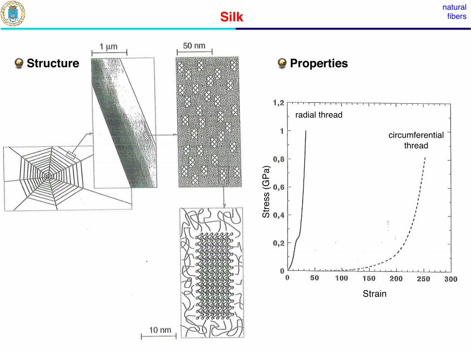
Silk
300 nm long and 1.5 nm in diameter
Silk fiber is the secretory product of the spinning glands of a variety of insects and spiders.
Silks are nanocomposites based on polypeptides. They are made up of an amorphous network of one protein (about 55-60%) reinforced by stiff, nanocrystalline regions of another protein.
Silk provides outstanding mechanical properties in terms of strength and ductility and the properties can be tailored for different applications.
natural fibersSilk
Strain
Stre
ss (G
Pa)
radial thread
circumferentialthread
Structure Properties

Synthetic organic fibersAramid
Aramid fibers are based aromatic polyamide chains. They are closely related to nylon, another polyamide fiber.
Polyamide
R = Rʼ= CH2
Aramid
Nylon
R = Rʼ= aromatic ring
Structure:

Aramid
Processing: The presence of aromatic groups reduces the solubility of aramid fibers, and they cannot be processed by conventional drawing techniques. Instead, they are spun from liquid crystalline polymer solutions. The critical point is to obtain a polymer solution in which the polymer chains are ordered forming a liquid crystal. This is achieved under certain critical conditions of temperature (100ºC), solvent (H2SO4), concentration (20%) and molecular weight.
Synthetic organic fibers

Aramid
Properties:
! - Strong, stiff fiber with high elongation to fracture (may reach 3.5-4.0% in ! Kevlar 29), which makes aramid suitable for protection against impact.
! - Compressive strength is about 1/8 of the tensile strength due to the ! anisotropic structure.
! - Good damping properties.
! - Sensitive to UV radiation (300 -400 nm), which leads to the breakage of ! chemical bonds and degradation of mechanical properties
Synthetic organic fibers

Polyethylene
Polyethylene (PE) fibers are made up of ultra-high molecular weight PE chains (> 106) oriented along the fibers axis. The fiber structure is highly crystalline
Structure: The actual density of PE fibers is very close to theoretical one (0.998 g/cm3)
Synthetic organic fibers
Processing: UHMW PE fibers are processed by gel-spinning. In the process, a swollen fiber network consisting of folded chains with solvent between them is drawn at 120ºC. The draw ratio can be as high as 200, leading to the orientation of the PE chains along the fiber axis.
Single crystal PE unit

Polyethylene
Properties:
! - Strong, stiff fiber with high elongation to fracture (3.5%) and very low !density.
! - Melting temperature of PE is very low and PE fibers undergo creep around !100ºC.
! - PE fibers present poor wettability to most polymer matrices, leading to ! infiltration problems. Plasma surface treatments introduce polar and functional groups in the surface and increase the roughness, improving the adhesion.
Synthetic organic fibers

Carbon
Carbon fibers are based on the unusual properties of graphite, one of allotropic forms of carbon.
Synthetic organic fibers
Graphite
- Basal planes with hexagonal C structures based in very strong C-C bonds (≈ 525 kJ/m2)
- Basal planes are linked by weak Van der Waals (< 10 kJ/m2), leading to ABAB... structure.
- Extreme anisotropy in stiffness (≈ 1000 GPa / ≈ 35 GPa)- High thermal and electrical conductivity along the graphene sheets

CarbonSynthetic
organic fibers
Structure: The main feature of C fibers is the orientation of the graphitic sheets along the fiber direction. The degree of alignment of the microstructure depends on the processing route (nature of the precursor, heat treatment temperature, etc.). In general, graphitic ribbons are oriented more or less parallel to the fibers axis, with random interlinking of the layers.
CarbonSynthetic
organic fibers
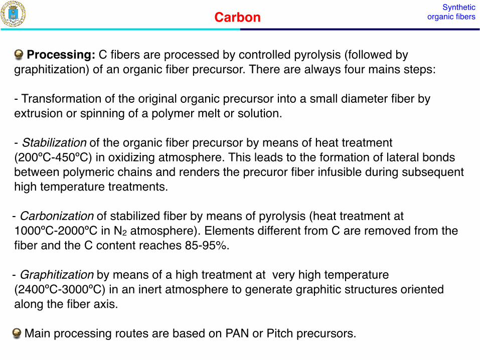
Processing: C fibers are processed by controlled pyrolysis (followed by graphitization) of an organic fiber precursor. There are always four mains steps:
- Transformation of the original organic precursor into a small diameter fiber by extrusion or spinning of a polymer melt or solution.
!- Stabilization of the organic fiber precursor by means of heat treatment (200ºC-450ºC) in oxidizing atmosphere. This leads to the formation of lateral bonds between polymeric chains and renders the precuror fiber infusible during subsequent high temperature treatments.
- Carbonization of stabilized fiber by means of pyrolysis (heat treatment at 1000ºC-2000ºC in N2 atmosphere). Elements different from C are removed from the fiber and the C content reaches 85-95%.
- Graphitization by means of a high treatment at very high temperature (2400ºC-3000ºC) in an inert atmosphere to generate graphitic structures oriented along the fiber axis.
Main processing routes are based on PAN or Pitch precursors.

CarbonSynthetic
organic fibers
Processing based on PAN: polyacrylonitrile (PAN) is the most common precursor to manufacture C fibers:
- PAN polymer fibers are spinned, followed by the stabilization treatment, which is carried out under tension to align the polymeric chains. Carbonization is carried out in between 1000ºC - 1500ºC, leading to a well-developed hexagonal network of C. Final graphitization controls the fiber properties.

CarbonSynthetic
organic fibers
Processing based on pitch: Pitches are low cost by products coming from petroleum cracking. Main sources are pitch are petroleum asphalt, coal tar and PVC. They are made up by a complex mixture of high molecular weight aromatic hydrocarbons.
- The first step is the spinning pitch filaments from a mesophase pitch with a nematic (liquid crystalline) structure. Centrifugal and jet spinning are often used to obtain a better alignment of the crystalline domains. Final steps include stabilization, carbonization and graphitization, as usual.
- Pitch is a cheap source of precursors but the variations in the composition may lead to variability of the final properties.
Sizing: Commercial C fibers have a size, protective surface coating to provide ease of handling (rubbing of fibers can lead to defect formation) and to improve adhesion with polymeric matrices.
- Low-molecular weight epoxy resins are commonly used for sizing.
- Oxidative treatments are also given to increase roughness and improve adhesion

CarbonSynthetic
organic fibers
Properties:
- C fibers are very anisotropic due to their graphitic structure. They are very strong and stiff in the fiber direction, and the properties depend on the amount of graphite and the orientation of the basal planes along the fibers. This leads to a variety of fibers
- Strength of C fibers is controlled by the presence of defects (inclusions, void).
- C fibers have good thermal and electrical conductivity and negative CTEin the fiber direction.
- High Modulus fibers are more sensitiveto defects and have lower strength. They present higher conductivity along the fiber and lower (more negative) CTE.
- Transverse properties of C fibers are very different: E≈20-40 GPa,CTE = 10-5ºC-1.

Synthetic ceramic fibers
Glass fibers are amorphous fibers based on SiO2. They are the backbone of information technology. We will focus in glass fibers for composite reinforcement.
- Raw materials to manufacture glass fibers are abundant and cheap. Processing route is unsophisticated: cheap glass fibers are readily available for reinforcement.
Structure: glass fibers are amorphous.
Composition:
- Glass fibers are based on SiO2 (≈ 50-60%) and contain a host of other metallic oxides. Different properties can be obtained by changing the chemical composition:
! - E glass (standard): 55% SiO2, 19 % CaO, 8% Al2O3, 7% Li2O! - C glass (corrosion resistant): 65% SiO2, 14% CaO, 9% Na2O, 5% Li2O, 4% Al2O3! - S glass (high strength): 65% SiO2, 25%Al2O3, 10% MgO
Glass

Synthetic ceramic fibers
Processing: glass fibers are manufactured by direct melting of a mixture of raw oxides, followed by drawing of the molten glass through electrically heated Pt bushes. Take up speeds are as high as 50 m/s.
- Organic sizing (e.g. starch oil) is applied on the fiber surface to protect from chemical attack and enhance wettability with polymeric matrices, followed by stretching by the take-up spool.
Glass

GlassSynthetic
ceramic fibers
Properties: glass fibers are isotropic and present isotropic properties
- The may have high strength but the stiffness is limited. Thus, the specific stiffness is low.
- They are resistant to fire and many chemicals but moisture (water adsorption) can lead to a important reduction in strength.
- E glass is corroded in alkaline environments (cement).
- Mechanical properties decay rapidly above 400ºC-500ºC due to melting. The melting temperature (and the viscosity) increase with the SiO2 content.
- Glass fibers are the standard reinforcement for low-added-value composite applications in engineering which specific stiffness is not critical (civil construction, marine and automotive markets, etc.)

SiCSynthetic
ceramic fibers
SiC fibers are of particular interest for high temperature applications. There are two types of SiC fibers (with different structure and properties) depending on the processing route.
Structure: Polycrystalline SiC fibers of ≈ 100- 150 µm in diameter are grown by CVD on a W or C fiber.
- The external fiber sheath is made up of ß-SiC with some alpha-SiC near the core. The 111 planes in SiC are parallel to the fiber axis.
Processing:
- CH3SiCl3 (g) ----> SiC (s) + 3 HCl (g)
- Reaction takes place at 1000ºC in an atmosphere of H2 (70%) and CH3SiCl3 (30%)
- Processing of a 100 µm fiber takes 20s.
CVD-processed SiC fibers

Synthetic ceramic fibersSiC fibers from polymer precursor
Structure: small diameter (10-20 µm) SiC fibers can be obtained by pyrolysis of a polymer precursor
- Fiber composition is a mixture of SiC, SiO2 and free C. Chemical composition is 59% Si, 31% C, and 10% O
Processing:
- Polymer precursor -[CH3-Si-CH3]n- is treated at 470ºC leading to polycarbosilane with 1500 MW.
- Polycarbosilane is melt spun at 350ºC in N2 to obtain a fiber precursor.
- Fiber precursor is stabilized (190ºC in O2) and then pyrolyzed at 1300ºC in vacuum.

SiCSynthetic
ceramic fibers
Properties: CVD-derived fibers
- Very high elastic modulus, chemical stability and strength retention at high temperature due to the stoichiometric composition.
- Very expensive (due to processing route) and limited flexibility. They cannot be weaved and are used as monofilaments.
Properties: polymer-derived fibers
- Low elastic modulus, and poor strength retention above 700ºC due to the non-stoichiometric composition.
- They are flexible and can be used in textile preforms.

SiC whiskers Synthetic ceramic fibers
Whiskers are monocrystalline, short fibers of extremely high strength, approaching the theoretical value for single crystals (E/10, E/20)
- Their diameter is small (<1 µm) and present very high aspect ratio (50 to 10000)
- Whiskers are normally obtained by vapor phase growth. This technique is very expensive.
- In 1970, a new technique was developed to obtain SiC whiskers from rice hulls (by-product of rice milling):! - Rice hulls are pyrolyzed at 700ºC in absence of O to drive out volatile compounds.! - SiC particles are whiskers are obtained from pyrolyzed rice hulls according to:
! ! 3C + SiO2 ----> SiC + 2C- SiC particles and whiskers (aspect ratio ≈ 75) are separated by a wet route.
Properties:
- Extremely high strength and hardness. - Inhalation may cause health problems

Al2O3Synthetic
ceramic fibers
Al2O3 fibers are of particular interest for high temperature and/or oxidation resistant applications.
Structure:
- Polycrystalline Al2O3 fibers of ≈ 10 µm in diameter are obtained by a sol-gel route.
- They can contain different amounts of SiO2, leading to fibers of different grade. Glassy phases are found at the grain boundaries.
Processing:
- An organic Al salt solution -starting material- is polymerized and spun to form a precursor fiber.
- Fiber is calcined at 1400ºC under careful conditions to obtain the inorganic fiber.

Synthetic ceramic fibers
Properties:
- They are inherently stable at very high temperature in oxidizing atmospheres. Very good resistance to fire. Low thermal and electrical conductivity. Good insulation properties.
- Mechanical properties decay rapidly above 700ºC due to creep promoted by grain-boundary sliding.
Al2O3

Synthetic metallic fibers
Processing: Wire drawing
- Metallic fibers of up to 100 µm in diameter are processed by conventional wire drawing. Hot drawing in normally used for refractory metals.
Metallic Fibers
Processing: Taylor process
- Metallic fibers below 100 µm in diameter can be obtained using the Taylor process, in which the metal is encapsulated in a glass sheath.
- The glass must not react with the metal at the drawing temperature, the glass viscosity at the drawing temperature should be low, the glass CTE should be equal to or slightly lower than that of the metal, and the glass must become highly viscous before the metal solidifies

Synthetic metallic fibers
Structure:
- Due to the drawing process, metallic fibers are normalized made up of highly textured, small diameter, elongated grains. The dislocation and other defect density within the grains is very high.
Metallic Fibers
Properties :
- They present high strength and low ductility, as a result of work-hardening.
- The strength values are very reliable (high Weibull modulus) as compared with ceramic and C fibers.
- Good thermal and electrical conductivity.
- Rapid degradation of properties with temperature (exception refractory metals) as a result of grain growth, recrystallization and creep.

Summary of fiber properties

Comparison of fiber properties
density Cost ratio
Tensile strength Elastic modulus

Fiber flexibility & maximum curvature Flexibility
- Fiber flexibility (its ability to be bent to an arbitrary radius without breaking) is important in many operations (weaving, braiding, winding, etc,). It is mainly controlled by the fiber diameter.
Flexibility = MMκ
M=
1EI
=64π
1Ed4
curvature Radius of curvatureκ 1/κ
Maximum curvature before fiber fracture
σmax =M
I
d
2=
Eκmaxd
2−→ κmax =
2σmax
Ed
FIBER(mm-1)
SiC CVD 0,08SiC polymer 1,4
Aramid 3,8E glass 4,8
HM carbon 1,4HS carbon 2,7
κmax

Weibull model for fiber strength fiber strength
Tensile fiber fracture of stiff, strong fibers for composite reinforcement is controlled by surface defects.
Weibull model of fiber fracture (weakest link probability)
Fiber length L L =N
i=1
N∆Li
∆Li
is the number of defects per unit length which lead fiber fracture when the applied tensile stress is equal to or greater than nσ
σ
Fiber survival probability under an applied stress σ
F =N
i=1(1− nσ∆Li) ≈ exp(−nσL)
Weibull function nσ =1L0
σ
σ0
m
F = 1− F = exp−L
L0
σ
σ0
m
characteristic strengthL0 characteristic lengthm Weibull modulus
σ0

Weibull model parameters fiber strength
Weibull modulus m: defect size distribution Characteristic strength : Average defect size. It is linked to L0
1− 1/e
Effect of m Effect of L
σ0 σ0 σ0
σ0

Experimental characterization fiber strength
Tensile testing of a large number (N ≈ 30 -50) of fibers of length L0 The resulting strength are ordered according to
Experimental failure probability
m and are obtained by the least squares fitting of
σ1 < σ2... < σi < ... < σN
F =i− 0.5
N
ln ln 1
1− F
= m(lnσ − lnσ0)σ0
C fibers SiC monofilaments

Dry bundle strength fiber strength
Objective: determine the failure strength of a bundle of N fibers loaded in tension. Fiber properties: Section , , length L, Weibull parameters Ω m, σ0, L0
P = NΩ σ F = NΩ σ exp
−L
L0
σ
σ0
m
Maximum load dP
dσ= 0 =⇒ Pmax = NΩ σ0
L0
Lme
1/m
σbundle = σ0
L0
Lme
1/m
so, the dry bundle strength decreases with the bundle length and with m

index
Particles Short fibers Long Fibers:
- Definitions- 1D: ! - Unidirectional lamina
! - Multidirectional laminates! - Weave- 2D:! - Knit! - Braid! - Nonwovens
! - Weave- 3D: ! - Non-crimp fabrics
- Stitching

Particles
Particles are reinforcements with approximately the same dimension in all directions.
- The most relevant parameter is the particle volume fraction. In the case of spherical particles, the maximum volume fraction is 74% for a regular arrangement (HCP) and 66% for random arrangement.
- Matrix infiltration is very difficult for volume fractions > 50% and typical volume fractions are in the range 20%-30%
- Homogeneous particle distribution is important to obtain good infiltration and properties.

short fibers
Short fibers are characterized by their length (in the range 100 µm - several mm) and high aspect ratio
- The most relevant parameters are:
! - Fiber volume fraction! - Average length and length distribution
! - Fiber orientation in 2D (lamina) or 3D (space): it is given by
! ! (2D)
l = ∞
0P (l) dl
p(θ) π/2
−π/2p(θ) dθ = 1
f

Definitions
Yarn: multifiber assembly characterized by a number of parameters:! - Linear density measured in denier (mass in grams of 9 km of yarn) or tex ! (mass in grams of 1 km of yarn).! - Number of fibers in the filament! - Twist: S (counterclockwise) or Z (clockwise)
Crimp:! Waviness along the fiber (yarn) length
long fibers
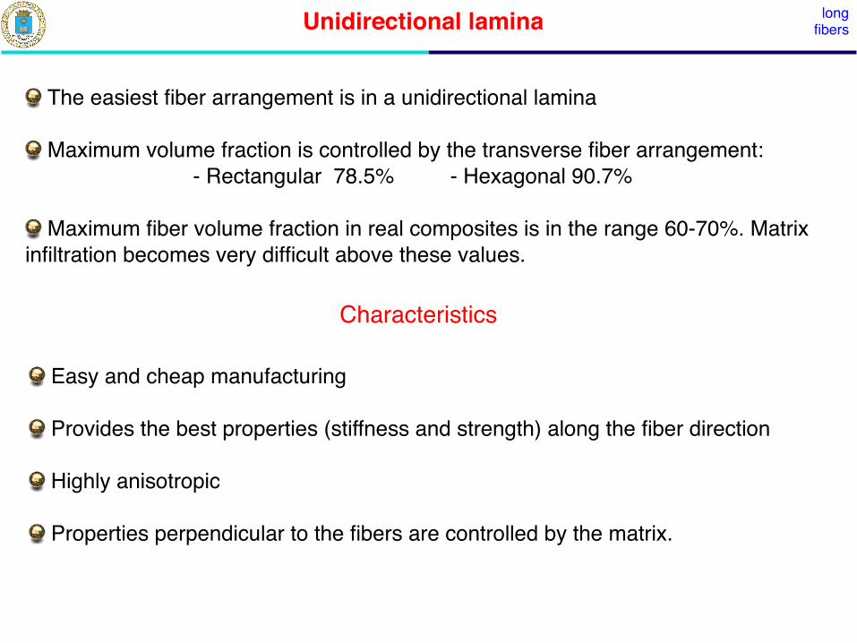
Unidirectional lamina
The easiest fiber arrangement is in a unidirectional lamina
Maximum volume fraction is controlled by the transverse fiber arrangement:! ! - Rectangular 78.5% ! - Hexagonal 90.7%
Maximum fiber volume fraction in real composites is in the range 60-70%. Matrix infiltration becomes very difficult above these values.
long fibers
Easy and cheap manufacturing
Provides the best properties (stiffness and strength) along the fiber direction
Highly anisotropic
Properties perpendicular to the fibers are controlled by the matrix.
Characteristics

Multidirectional laminates
Multidirectional laminates are built by stacking unidirectional lamina with different orientations
long fibers
They take advantage of the good properties of unidirectional lamina and can provide quasi-isotropic properties in the laminate plane
Poor strength in the perpendicular direction and susceptible to interply delamination during bending (leading to poor drapability)
Characteristics
[0/90/0/0/90/0][0/90/02/90/0][0/90/0]s
[0/60/-60/-60/60/0][0/60/-602/60/0][0/60/-60]s
cross-ply
MM
MM

Woven fabrics
Woven fabrics are planar textile preforms obtained by weaving two sets yarns at 0º and 90º. A planar weave provides a firm construction (very little slippage)
Plain
fill or weft direction
war
p
Satin
Twill 2 x 2 twill 3 x 1 twill
2D fabrics

Woven fabrics
Better drapability than multidirectional laminates, which increases with the number of binders by unit area (lower harness).
Orthogonal in-plane properties.
Lower susceptibility to interply delamination.
Larger design envelope (hybrid textiles, different fiber volume fraction in warp and weft directions, fabric type).
Lower stiffness (due to crimp) and strength than multidirectional laminates.
Higher processing costs than unidirectional laminates (weaving).
Characteristics
2D fabrics

Knitted fabrics
High deformability in all directions.
Characteristics
Woven fabrics are planar textile preforms obtained by interlooping one set of yarns, i. e. drawing loops of one yarn in the previous one.
Straight warp and/or filling yarns can be added to increase stiffness.
2D fabrics

Braided fabrics
Characteristics
Braided fabrics are textile preforms obtained by interlacing yarns in the bias direction. They are similar to rotated woven fabrics.
Braided fabrics are often created over a mandrel to make flat or tubular products.
Braided fabrics combine high torsional stiffness with large deformability in tension.
2D fabrics

Nowoven felts 2D fabrics
Characteristics
Nonwoven felts are materials manufactured from a set of disordered fibers consolidated by bonds of different nature, such as simple entanglement, local thermal fusion or chemical binders.
Cheaper than their textile counterparts, have lower strength and stiffness and higher deformability and energy absorption capability.
2 mm

3D fabrics 3D fabrics
3D fabrics are manufactured to improve the strength and stiffness of textile preforms in the direction perpendicular to the fabric.
Woven fabricsmultiaxial weaving (interlock) 3D orthogonal weaving

Non-crimp fabrics 3D fabrics
Characteristics
Non crimp fabrics are multidirectional laminates made up of unidirectional plies with different fiber orientation that are assembled and stitched together.
In-plane mechanical properties are enhanced by the absence of crimp. Interply delamination is inhibited by the 3D stitching.

Stitching long fibers
Multidirectional laminates and/or 2D textile preforms are stitched to improve out-of-plane mechanical properties
Modified lock stitchLock stitch Chain stitch
Patterns
METALLIC MATRICES
Metals and metallic alloys present excellent mechanical properties (stiffness, strength, ductility, toughness) and functional properties (high thermal and electrical conductivity) as a result of their metallic bonding.
Main deformation mechanism is dislocation slip. Properties can be tailored to a large extent by adding alloying elements, leading to the formation of second phases or solid solutions which modify dislocation movement.
Main limitations are high density, limited hardness, low melting temperature for specific applications (power generation), and elevated chemical reactivity at high temperature.
A wide range of metals and metallic alloys can be used as matrices for metal-matrix composites (MMC). The most common ones are light alloys because:! - Low melting temperature that facilitates infiltration without damaging the fibers.! - They are the most suitable candidates to improve specific stiffness and strength ! as well the high temperature mechanical properties (creep)
METALLIC MATRICES
Molten metallic alloys are very reactive, leading to chemical reaction with the reinforcement. Fiber coatings, processing in solid state (powder metallurgy), rapid solidification techniques, modifications in the matrix chemical composition etc ... have to be used to avoid this problem.
Processing of MMC always requires high temperatures (> 400ºC) and polymeric fibers cannot be used for reinforcement.
Al alloys, particularly cast Al-Si alloys and wrought Al-Cu alloys. Molten Al alloys have low viscosity, and they can be easily with SiC or Al3O2 particles to increase hardness, wear resistance and the specific stiffness and strength.
Ti alloys (Ti-6Al-4V) can be reinforced with ceramic fibers (SiC, C) to manufacture composite with very high specific properties for high temperature applications (600ºC).

CERAMIC MATRICES
Ceramic materials present low density, elevated stiffness, compressive strength and creep resistance, hardness, melting point and chemical stability in aggressive environments at high temperature. Their conductivity and CTE are low.
Their main drawback from the viewpoint of mechanical properties are the very poor toughness and ductility, which makes ceramic components prone to catastrophic failures. Their thermal shock resistance is also very limited.
Ceramic reinforcement is mainly focussed in improving the toughness and tensile ductility. !
Engineering ceramics (SiC, Al2O3, Si3N4) are crystalline solids with strong covalent or ionic bonding.
Glass-ceramics (based on SiO2-Al2O3-MgO, SiO2-Al2O3-Li2O) are made up of fine crystalline ceramic particles (< 1 µm) embedded in a glassy matrix. Their mechanical properties are lower than those of engineering ceramics but they can processed at lower temperatures.
Cement is the most widely used ceramic matrix because it can be easily processed by mixing aggregates (gravel and sand), cement and water.

CERAMIC MATRICES
Carbon can be found in nature in various allotropic forms (amorphous, diamond, graphite, etc.). It presents low density, very high melting point and strength retention up to this temperature (in absence of oxygen) and very low CTE (leading to excellent thermal shock resistance). Some allotropic forms also present high electrical and thermal conductivity.
Processing of ceramic-matrix composites (CMC) is always hard because of the difficulties associated with the infiltration of the ceramic matrix into the fiber preform. Liquid routes are not allowed by the high melting point of the matrix, which will lead to fiber degradation.
Improvement of the toughness and strength is important in selected cases but processing costs often hinder the practical applications.
Carbon-matrix composites are the most widely used CMC (besides concrete) due to the unique set of properties of carbon, which makes this material the only choice for specific applications.

POLYMERIC MATRICES
Polymeric matrices are the most widely used to manufacture composites because they are easy to infiltrate in the fiber preform and present limited cost. Two main types of polymeric matrices are thermosets (resins) and thermoplastics.
Thermoset are polymers with branched chains. They are formed in situ by a chemical reaction (curing) between two polymers (resin and hardener) or a resin and catalyst, leading to three-dimensional network in which covalent bonds link different polymeric chains.
Once cured, thermosets do not become liquid again if heated, although their mechanical properties will decrease significantly above Tg. Above Tg, the molecular structure changes from that of a rigid network to a flexible one. This change is reversible.
Thermosets are low viscosity liquids are room temperature and can be easily infiltrated into the fiber preforms. They are cheap, present high stiffness and strength, good resistance to chemical attacks and the standard matrices for PMC
Main limitations are brittleness and limited high temperature capabilities (particularly under hot/wet conditions)
THERMOSETS

POLYESTER RESINS
(unsaturated) Polyester resins are the most widely used matrices as a result of their low cost, good processability and environmental resistance. Particularly popular in marine industry are used in all applications which do not require extreme properties.
Most polyester resins are viscous liquids consisting of a solution of apolyester in styrene. The addition of styrene (up to 50%)reduces the viscosity and enables resin curing by cross-linking of the polyester molecular chains without the generation of by-products. They can be moulded without pressure.
Thermosets
Polyester resins have a limited storage life as they will polymerize on their own over a long period of time. Inhibitors are often added during manufacturing to increase the usable life. Curing of polyester resins is accelerated with a catalyst which does not take part in the chemical reactions.
Isophthalic polyester
uncured polyester
cured polyester + styrene network

VINYLESTER RESINS
Similar to polyester resins but with the active groups at the end of the chain and fewer ester groups.
Thermosets
uncured vinylester
cured vinylester + styrene network
Ester groups are susceptible to water degradation by hydrolysis and vinylesters exhibit better resistance to water and other chemicals than polyester resins.
The reactive sites are located at the end of the chain and this leads to longer chains with higher capacity to absorb energy during deformation (tougher).
Vinylester resins are often used in petrochemical industry.

EPOXY RESINS
Epoxy resins stand among the thermosets with better properties as matrices. The normally outperform most of the thermosets in mechanical properties and environmental resistance.
Epoxy refers to a chemical group consisting of an O atom bonded to two C atoms that are already bonded in some way.
Thermosets
Ethylene Oxide
Diglycidyl Ether of Bisphenol-A
Epoxies are cured with a “hardener” (often an amine) through an addition reaction. Two epoxy sites at the end of the chain bind each amine site, leading to a complex 3D chain network.
Proportions of epoxy and amine are fixed to optimize curing.

EPOXY RESINS
Epoxy molecules do not have ester groups, leading to very good chemical resistance. The epoxy molecule also contains two ring groups at its center which are able to absorb both mechanical and thermal stresses better than linear groups and therefore give the epoxy resin very good stiffness and heat resistant properties and electrical insulators. They normally outperform most of the thermosets in mechanical properties and environmental resistance are used in high-added value applications (aerospace).
Epoxy resins have low viscosity and are easily and quickly cured at any temperature from 50 ºC to 150ºC, depending on the choice of curing agent. One of the most advantageous properties of epoxies is their low shrinkage.
Epoxy resins are brittle (as all resins) are sometimes mixed with thermoplastic particles to increase the toughness. In addition, their mechanical properties are severely reduced under hot-wet conditions (70ºC-85% RH)
Thermosets

COMPARISON THERMOSETSThermosets
Mechanical Properties
Water adsorption

COMPARISON THERMOSETSThermosets

OTHER THERMOSETSThermosets
Phenolic resins, primarily used where high fire-resistance is required.
Bismaleimides (BMI), primarily used in aircraft composites where operation at higher temperatures (230 ºC wet/250 ºC dry) is required. e.g. engine inlets, high speed aircraft flight surfaces. Very expensive. (>£50/kg).
Polyimides, used where operation at higher temperatures than BMI can stand is required (up to 250 ºC wet/300 ºC dry). Typical applications include missile and aero-engine components. Extremely expensive (>£80/kg), which uses toxic raw materials in its manufacture. Polyimides also tend to be hard to process due to their condensation reaction emitting water during cure, and are relatively brittle when cured.

SELECTIONThermosets
THERMOSET CURINGThermosets
On addition of the catalyst or hardener a resin will begin to become more viscous until it reaches a state when it has lost its ability to flow: gel point.
The resin will continue to harden after it has gelled until, at some time later, it has obtained its full hardness and properties. This reaction itself is accompanied by the generation of heat, which, in turn, speeds the reaction. The whole process is known as the ʻcuringʼ of the resin.
The speed of cure is controlled by the amount of accelerator in a polyester or vinylester resin and by the type of hardener in an epoxy resin. Generally polyester resins produce a more severe exotherm and a faster development of initial mechanical properties than epoxies of a similar working time.
With both resin types, however, it is possible to accelerate the cure by the application of heat. Curing at elevated temperatures has the advantage that it actually increases the end mechanical properties of the material. Many resin systems will not reach their ultimate mechanical properties unless the resin is given a heat treatment after curing, which increases the mechanical properties and Tg.

THERMOPLASTICSThermosets
Thermoplastics are polymers that turn to a liquid when heated and freeze to a very glassy state when cooled sufficiently. Most thermoplastics are high-molecular weight polymer whose chains associate through weak Van der Waals bonds (polyolefins), hydrogen bonds (nylon) or even stacking of aromatic rings (polystyrene).
Thermoplastics can have amorphous or semi-crystalline structure, alternating crystalline regions with amorphous regions in which the chains approximate random coils. They normally present higher ductility and toughness than thermosets below Tg, and both properties increase very rapidly above Tg while the strength decreases. Above Tg, the amorphous chains change from a glassy to a rubbery phase. Above Tm, viscosity gradually decreases without any distinct phase change and thermoplastics become viscous liquids that can be infiltrated into fiber preform.
Thermoplastics can go through melting/freezing cycles repeatedly and can be remelted and remoulded.
Polyolefins (PE, PP), polyamides (nylon) and polysterene, often used in engineering applications, can be reinforced with particles or short-fibers to improve stiffness, strength, barrier properties, etc.
Specific thermoplastics for composites include PEE and PES.

PPS (Polyphenylene Sulfide) is semicrystalline thermoplastic consisting of aromatic rings linked with sulfides. Very good checmical resistance and good mechanical properties. (elastic modulus 3.6 GPa, tensile strength 90 MPa, Tg = 90 °C, Tm = 280 °C)
THERMOPLASTICSThermosets
PEEK (Polyetheretherketone) is a semicrystalline thermoplastic with excellent mechanical properties and chemical resistance that are retained to high temperatures. (elastic modulus 3.6 GPa, tensile strength 100 MPa, Tg = 143 °C, Tm = 343 °C). It is highly resistant to thermal degradation as well as attack by both organic and aqueous environments.

COMPARISON
THERMOSETS THERMOPLASTICS
Advantages Advantages
Cheap! ! Rapid, reversible processingLow viscosity, easy to infiltrate! ! Uncontrolled shelf lifeHigh strength and stiffness! ! High toughness and delamination resistanceLow processing temperature! ! Reusable scrap and recyclability Good fiber wetting! ! Reparability and joining by welding! ! Elevated temperature mechanical properties! ! No residual stresses in components !
!
Disadvantages Disadvantages
Long, irreversible processing! ! ExpensiveLimited shelf life! ! High processing temperatureBrittle! ! Difficult to infiltrate (high viscosity/low flow)High strength and stiffness! !Limited high temperature capabilities !Difficult to recycle Residual stresses in components! ! !

References
- SP Guide to Composites. www.spsystems.com

THE IMPORTANCE OF BEING INTERFACIAL
Internal area occupied by fiber-matrix interfaces is very large in composites (of the order of 3000 m2/m3 in a composite containing a reasonable fiber volume fraction)
The properties of the matrix around the interface can be modified by the presence of the fiber. Fiber surface/volume ratio varies with 2/r, and the importance of the interfacial zone increases as the fiber radius decreases. In the extreme case of nanoparticle (10-100 nm in diameter) reinforcement, dramatic changes in the composite properties can be achieved with very small volume fractions (≈ 1%)
Matrix-fiber interaction (infiltration, load transfer, etc.) is carried out through the interface.
Design of composites with optimum properties needs a detailed knowledge of the interfacial region. Moreover, interface properties can be modified by the application of coatings.

WETTABILITY
Most matrices are infiltrated into a fiber preform. Easy infiltration depends on the ability of a liquid to spread on a solid surface: wettability.
SOLID
LIQUID
∆G < 0
∆G = γsl − γlv − γsv < 0SOLID
LIQUID
VAPOR
γsl < γlv − γsv
Actual wetting takes place by spreading a drop of liquid onto a surface.
SOLID
LIQUIDγslγsv
γlv
θ
γsv = γsl + γlv cos θ
Wettability condition:" in practice:
γsv > γsl + γlv
γsv > γlv
(J/m2) (J/m2)
Epoxy 0,043polyester 0,035E glass 0,56Carbon 0,07
PE 0,03
γsvγlv

INTERFACIAL BONDING
Wettability is different from bonding. Bonding is necessary for a good interaction between matrix and fibers in the composite (load transfer, conductivity, etc.)
Mechanical bonding is due to the interlock effect between two rough surfaces.
- It is enhanced by good wettability, that leads to an intimate contact between matrix and fibers, and by thermal residual stresses that arise upon cooling from infiltration when
- It may be very effective in shear, increasing dramatically the friction coefficient. But it does no provide a strong bond perpendicular to the interface.
αm > αf
Physical bonding due to presence of Van der Waals, hydrogen and electrostatic forces. It is normally very weak (≈ 10 kJ/m2)

INTERFACIAL BONDING
Chemical bonding at the interface involving atomic or molecular transport. It may be assisted by diffusion or chemical reactions.
Solid solution and new chemical species can appear at the interface, leading to the development of an interfacial reaction zone with a certain thickness. Energies associated with chemical bonds are in the range 40 - 400 kJ/m2.
Chemical bonds appear in PMC by the diffusion of the organic sizing into the polymeric matrix network and in MMC and CMC by chemical reaction between matrix and fibers.
4Al + 3SiC ----> Al4C3 + 3Si3Mg + 4 Al2O3 -----> 3Mg Al2O4 + 2Al
The thickness of the interfacial zone varies according to
Thick reaction zones are normally deleterious for the properties. The thickness of the reaction zone can be controlled by changing the equilibrium constants of the chemical reaction and/or infiltration temperature.
x ∝√
t ∝ exp −Q
2RT
√t

INTERFACIAL BONDING
Residual stresses develop in composite materials upon cooling after processing due to the CTE mismatch between matrix and fibers. They also appear during operation as a result of thermal exposure.
"
= coefficient of thermal expansion. Matrixʼs CTE is often higher than fiberʼs CTE.
Polymers also absorb water from the environment. Water absortion leads to an increase in volume.
= coefficient of moisture expansion.
In addition to an increase in volume, absorbed water reduces the elastic modulus and the glass transition temperature, increases fracture strain and impact resistance.
As a result of higro-thermal residual stresses, matrix is loaded in tension and reinforcements in compression. This enhances interfacial bonding.
v = 3x =∆V
V= 3α∆T
α
∆c =change in the mass of water per unit volume
mass of dry material per unit volumev = 3x =∆V
V= 3β∆c
β

INTERFACIAL BONDING
Unidirectional reinforcement (isostrain approach)
0 = σm(1− f) + σff
m = f m = αm∆T +σm
Em= f = αf∆T +
σf
Ef
σf =(αm − αf )∆T
Em(1− f) + EffEmEf (1− f) σm = − (αm − αf )∆T
Em(1− f) + EffEmEff
Spherical reinforcement
r
matrix residual stresses
σrm = K
r
R
3
σθm = −K
2
r
R
3
K = f(Em, Ef , νm, νf ) ∆T (αf − αm)

INTERFACE MECHANICAL PROPERTIES
Interface mechanical properties are critical for the composite performance.
The interface mechanical behavior is characterized by 3 parameters:
"- Shear strength: shear stress parallel to the interface, leading to fracture.- Normal strength: normal stress perpendicular to the interface to fracture.- Interface fracture energy
In addition, frictional sliding during fiber pull-out after interface fracture is an important energy dissipation mechanisms characterized by the interface friction coefficient.
Unfortunately, these parameters are not always easy to determine accurately. A first estimation (qualitative) of the interfacial strength can be obtained by the ILSS test (a three-point bend test on a very short unidirectionally reinforced beam):
τILSS =3Pmax
DTD
P
S = 5D