whitePaper TEMPLATE rev4 -...
18
October 2004 QUALCOMM CDMA TECHNOLOGIES WHITE PAPER HSDPA for Improved Downlink Data Transfer
Transcript of whitePaper TEMPLATE rev4 -...
O c t o b e r 2 0 0 4
QU
AL
CO
MM
CD
MA
TE
CH
NO
LO
GIE
S W
HIT
E P
AP
ER
HSDPA for Improved Downlink Data Transfer
5775 Morehouse DriveSan Diego, CA 92121-1714 U.S.A.
Copyright © 2004 QUALCOMM IncorporatedAll Rights Reserved.
All trademarks and registered trademarks referenced herein are the property of their respective owners.
Page 2
HS
DP
A f
or
Imp
rov
ed
Do
wn
lin
k D
ata
Tra
ns
fer
Page 3
HS
DP
A fo
r Imp
rov
ed
Do
wn
link
Da
ta T
ran
sfe
r
Table of Contents
Executive Summary 4
1.0 HSDPA Concept and Key Features 51.1 HSDPA New Channel Structure 51.2 Adaptive Modulation and Coding 61.3 Hybrid-ARQ with Soft Combining 61.4 Fast Scheduling 71.5 Mobility 81.6 UE Capabilities 8
2.0 System and End-User Application Performance 92.1 HSDPA Link Budget and Peak Data Rates 92.2 HSDPA Sector Throughput 122.3 Applications and End-User Experience 13
3.0 HSDPA Evolution 14
4.0 Networks Economics 15
5.0 Conclusion 16
6.0 References 17
Page 4
HS
DP
A f
or
Imp
rov
ed
Do
wn
lin
k D
ata
Tra
ns
fer
Page 5
HS
DP
A fo
r Imp
rov
ed
Do
wn
link
Da
ta T
ran
sfe
r
Executive Summary
Data services are expected to have significant
growth over the next few years and will likely
become the dominant source of 3G traffic and
revenue. The current 3G operators in Japan and
Korea are already experiencing great success
with their data services. For example, DoCoMo’s
WCDMA-FOMA service is already generating
more than 20 percent of the total revenue with
4+ millions subscribers (through May 2004)
despite a modest start in 2001. SKT (South Korean
Telecom) has reported that 34 percent of its ARPU
was related to data usage for Q3-03 particularly
after the deployment of 1xEV-DO.
In order to meet the increasing demand for
high data-rate multimedia services, the 3rd
Generation Partnership Project (3GPP) has
released* a new high-speed data transfer
feature named High-Speed Downlink Packet
Access (HSDPA).
HSDPA provides impressive enhancements
over WCDMA R’99 for the downlink. It offers
peak data rates of up to 10 Mbps, resulting
in a better end-user experience for downlink
data applications, with shorter connection and
response times. More importantly, HSDPA offers
three- to five-fold sector throughput increase,
which translates into significantly more data users
on a single frequency (or carrier). The substantial
increase in data rate and throughput is achieved
by implementing a fast and complex channel
control mechanism based upon short physical
layer frames, Adaptive Modulation and Coding
(AMC), fast Hybrid-ARQ and fast scheduling.
HSDPA higher throughputs and peak data rates
will help stimulate and drive consumption of
data-intensive applications that cannot be
supported by R’99. In fact, HSDPA allows a more
efficient implementation of interactive and
background Quality of Service (QoS) classes, as
standardized by 3GPP. HSDPA high data rates
improve the use of streaming applications, while
lower roundtrip delays will benefit Web browsing
applications. Another important benefit of HSDPA
is its backwards compatibility with R’99. This
makes its deployment very smooth and gradual
on an as needed basis.
The deployment of HSDPA is very cost effective
since the incremental cost is mainly due to
Node Bs (or BTS) and RNC (Radio Network
Controller) software/hardware upgrades. In
fact, in a capacity-limited environment (high
subscriber density and/or data-traffic volume
per subscriber), the network cost to deliver a
megabyte of data traffic is about three cents for
a typical dense urban environment, as opposed
to seven cents for R’99 assuming an incremental
cost of 20 percent.
The ability to offer higher peak rates for an
increasingly performance-demanding end-
user at a substantially lower cost will create
a significant competitive advantage for
HSDPA operators. Supporting rich multimedia
applications and content and more compelling
devices at lower user costs will enable early
adopters to differentiate themselves with
advanced services, resulting in higher traffic
per user and increased subscriber growth, data
market share and profitability.
* Release 5
Page 4
HS
DP
A f
or
Imp
rov
ed
Do
wn
lin
k D
ata
Tra
ns
fer
Page 5
HS
DP
A fo
r Imp
rov
ed
Do
wn
link
Da
ta T
ran
sfe
r
1.0 HSDPA Concept and Key Features
R’99 already includes three different channels for
downlink packet data transmission: Dedicated
Channel (DCH), Downlink-Shared Channel
(DSCH) and Forward Access Channel (FACH).
The FACH is a common channel offering low
latency. However, it is not efficient since it does
not support fast closed loop power control. It is
therefore limited to carrying only small amounts
of data traffic. The DCH is the primary data
channel and can be used for any traffic class.
In the downlink, the DCH is allocated a certain
orthogonal variable spreading factor (OVSF:
4-512) according to the connection peak data
rate7, while the block error rate (BLER) is controlled
by inner and outer loop power control. The
DCH code and power allocation are therefore
inefficient for bursty and low duty cycle data
applications since channel re-allocation can be
very slow (in the range of 500 ms)5. The DSCH
provides the possibility to time-multiplex different
users, improving the channel re-allocation time5.
The HSDPA concept can be seen as an extension
of the DSCH with the introduction of new features
such as Adaptive Modulation and Coding
(AMC), short frames, multi-code operation, fast
L1 Hybrid-ARQ (HARQ) and Node B scheduling.
In fact, these features replace the two basic
WCDMA features, namely Variable Spreading
Factor (VSF) and fast power control5. This section
explains HSDPA key features.
1.1 HSDPA New Channel StructureA new transport channel named High-Speed
Downlink Shared Channel (HS-DSCH) has been
introduced as the primary radio bearer. Similar
to the DSCH, the HS-DSCH resources can be
shared between all users in a particular sector.
The primary channel multiplexing occurs in the
time domain, where each Transmission Time
Interval (TTI) consists of three slots (or 2 ms.) The
TTI is also referred to as a “sub frame.” The TTI has
been significantly reduced from the 10, 20, 40 or
80 ms TTI sizes supported in R’99 in order to better
achieve short round trip delay between the UE
(User Equipment) and the Node B, and improve
the link adaptation rate and efficiency of the
AMC (cf. section 1.2).
Within each 2 ms TTI, a constant Spreading Factor
(SF) of 16 is used for code multiplexing, with a
maximum of 15 parallel codes allocated to the
HS-DSCH. These codes may all be assigned to
one user during the TTI, or may be split across
several users. The number of parallel codes
allocated to each user depends on cell loading,
QoS requirements and the UE code capabilities
(five, 10 or 15 codes).
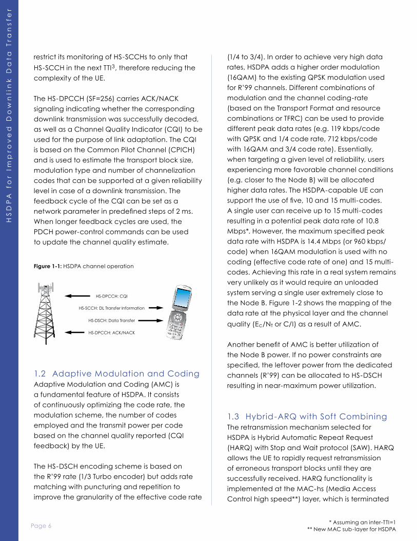
In order to support the HS-DSCH operation, two
control channels have been added: the High-
Speed Shared Control Channel (HS-SCCH) and
the High-Speed Dedicated Physical Control
Channel (HS-DPCCH).
The HS-SCCH is a fixed rate (60 kbps, SF=128)
channel used for carrying downlink signaling
between the Node B and the UE before the
beginning of each scheduled TTI. This includes
the UE identity (via a UE-specific CRC), HARQ-
related information and the parameters of the
HS-DSCH transport format selected by the link-
adaptation mechanism. Multiple HS-SCCHs can
be configured in each sector to support parallel
HS-DSCH transmissions. A UE can be allocated
a set of up to four HS-SCCHs, which it needs to
monitor continuously. In any given TTI, a maximum
of one of these HS-SCCHs may be addressed to
a particular UE. When a UE detects a message
addressed to it on a specific HS-SCCH, it may
Page 6
HS
DP
A f
or
Imp
rov
ed
Do
wn
lin
k D
ata
Tra
ns
fer
Page 7
HS
DP
A fo
r Imp
rov
ed
Do
wn
link
Da
ta T
ran
sfe
r
restrict its monitoring of HS-SCCHs to only that
HS-SCCH in the next TTI3, therefore reducing the
complexity of the UE.
The HS-DPCCH (SF=256) carries ACK/NACK
signaling indicating whether the corresponding
downlink transmission was successfully decoded,
as well as a Channel Quality Indicator (CQI) to be
used for the purpose of link adaptation. The CQI
is based on the Common Pilot Channel (CPICH)
and is used to estimate the transport block size,
modulation type and number of channelization
codes that can be supported at a given reliability
level in case of a downlink transmission. The
feedback cycle of the CQI can be set as a
network parameter in predefined steps of 2 ms.
When longer feedback cycles are used, the
PDCH power-control commands can be used
to update the channel quality estimate.
1.2 Adaptive Modulation and CodingAdaptive Modulation and Coding (AMC) is
a fundamental feature of HSDPA. It consists
of continuously optimizing the code rate, the
modulation scheme, the number of codes
employed and the transmit power per code
based on the channel quality reported (CQI
feedback) by the UE.
The HS-DSCH encoding scheme is based on
the R’99 rate (1/3 Turbo encoder) but adds rate
matching with puncturing and repetition to
improve the granularity of the effective code rate
(1/4 to 3/4). In order to achieve very high data
rates, HSDPA adds a higher order modulation
(16QAM) to the existing QPSK modulation used
for R’99 channels. Different combinations of
modulation and the channel coding-rate
(based on the Transport Format and resource
combinations or TFRC) can be used to provide
different peak data rates (e.g. 119 kbps/code
with QPSK and 1/4 code rate, 712 kbps/code
with 16QAM and 3/4 code rate). Essentially,
when targeting a given level of reliability, users
experiencing more favorable channel conditions
(e.g. closer to the Node B) will be allocated
higher data rates. The HSDPA-capable UE can
support the use of five, 10 and 15 multi-codes.
A single user can receive up to 15 multi-codes
resulting in a potential peak data rate of 10.8
Mbps*. However, the maximum specified peak
data rate with HSDPA is 14.4 Mbps (or 960 kbps/
code) when 16QAM modulation is used with no
coding (effective code rate of one) and 15 multi-
codes. Achieving this rate in a real system remains
very unlikely as it would require an unloaded
system serving a single user extremely close to
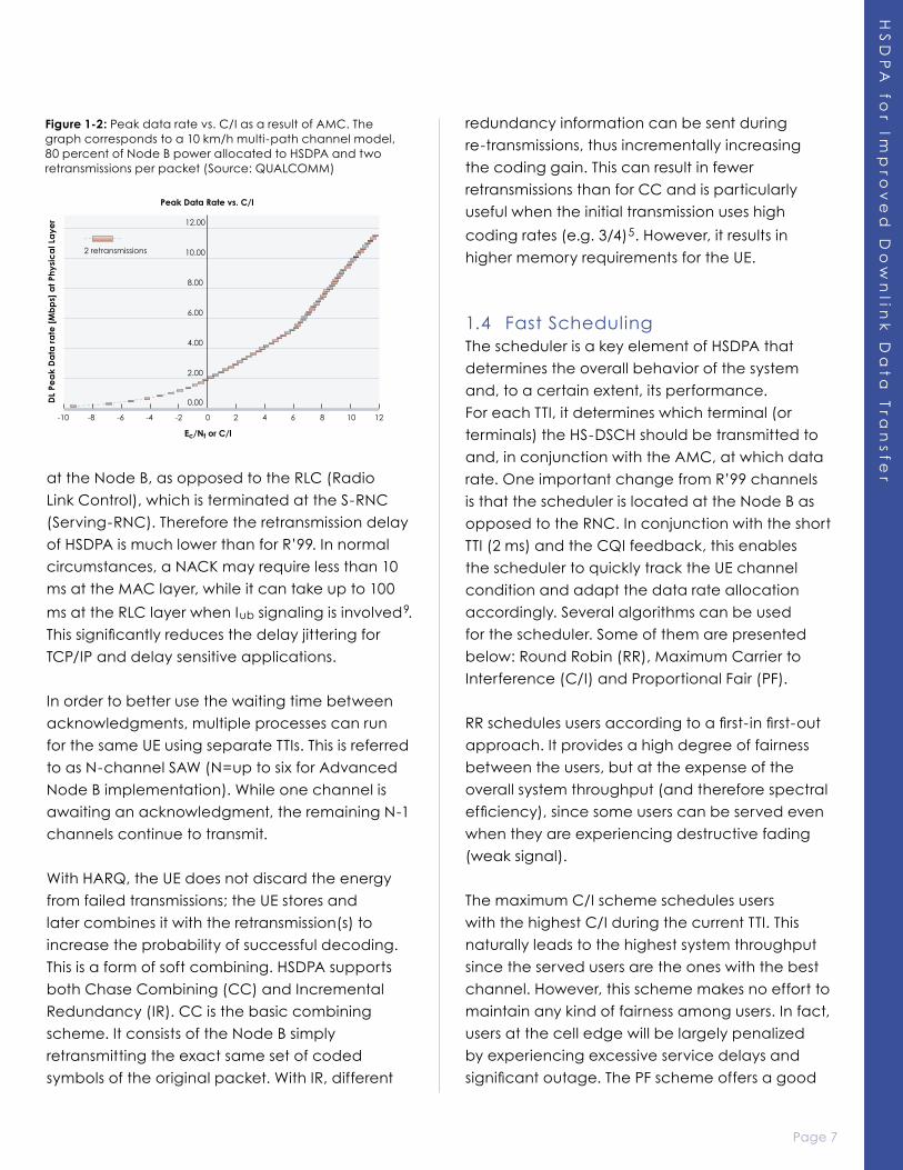
the Node B. Figure 1-2 shows the mapping of the
data rate at the physical layer and the channel
quality (Ec/Nt or C/I) as a result of AMC.
Another benefit of AMC is better utilization of
the Node B power. If no power constraints are
specified, the leftover power from the dedicated
channels (R’99) can be allocated to HS-DSCH
resulting in near-maximum power utilization.
1.3 Hybrid-ARQ with Soft CombiningThe retransmission mechanism selected for
HSDPA is Hybrid Automatic Repeat Request
(HARQ) with Stop and Wait protocol (SAW). HARQ
allows the UE to rapidly request retransmission
of erroneous transport blocks until they are
successfully received. HARQ functionality is
implemented at the MAC-hs (Media Access
Control high speed**) layer, which is terminated
Figure 1-1: HSDPA channel operation
* Assuming an inter-TTI=1** New MAC sub-layer for HSDPA
Page 6
HS
DP
A f
or
Imp
rov
ed
Do
wn
lin
k D
ata
Tra
ns
fer
Page 7
HS
DP
A fo
r Imp
rov
ed
Do
wn
link
Da
ta T
ran
sfe
rat the Node B, as opposed to the RLC (Radio
Link Control), which is terminated at the S-RNC
(Serving-RNC). Therefore the retransmission delay
of HSDPA is much lower than for R’99. In normal
circumstances, a NACK may require less than 10
ms at the MAC layer, while it can take up to 100
ms at the RLC layer when Iub signaling is involved9.
This significantly reduces the delay jittering for
TCP/IP and delay sensitive applications.
In order to better use the waiting time between
acknowledgments, multiple processes can run
for the same UE using separate TTIs. This is referred
to as N-channel SAW (N=up to six for Advanced
Node B implementation). While one channel is
awaiting an acknowledgment, the remaining N-1
channels continue to transmit.
With HARQ, the UE does not discard the energy
from failed transmissions; the UE stores and
later combines it with the retransmission(s) to
increase the probability of successful decoding.
This is a form of soft combining. HSDPA supports
both Chase Combining (CC) and Incremental
Redundancy (IR). CC is the basic combining
scheme. It consists of the Node B simply
retransmitting the exact same set of coded
symbols of the original packet. With IR, different
redundancy information can be sent during
re-transmissions, thus incrementally increasing
the coding gain. This can result in fewer
retransmissions than for CC and is particularly
useful when the initial transmission uses high
coding rates (e.g. 3/4)5. However, it results in
higher memory requirements for the UE.
1.4 Fast SchedulingThe scheduler is a key element of HSDPA that
determines the overall behavior of the system
and, to a certain extent, its performance.
For each TTI, it determines which terminal (or
terminals) the HS-DSCH should be transmitted to
and, in conjunction with the AMC, at which data
rate. One important change from R’99 channels
is that the scheduler is located at the Node B as
opposed to the RNC. In conjunction with the short
TTI (2 ms) and the CQI feedback, this enables
the scheduler to quickly track the UE channel
condition and adapt the data rate allocation
accordingly. Several algorithms can be used
for the scheduler. Some of them are presented
below: Round Robin (RR), Maximum Carrier to
Interference (C/I) and Proportional Fair (PF).
RR schedules users according to a first-in first-out
approach. It provides a high degree of fairness
between the users, but at the expense of the
overall system throughput (and therefore spectral
efficiency), since some users can be served even
when they are experiencing destructive fading
(weak signal).
The maximum C/I scheme schedules users
with the highest C/I during the current TTI. This
naturally leads to the highest system throughput
since the served users are the ones with the best
channel. However, this scheme makes no effort to
maintain any kind of fairness among users. In fact,
users at the cell edge will be largely penalized
by experiencing excessive service delays and
significant outage. The PF scheme offers a good
Figure 1-2: Peak data rate vs. C/I as a result of AMC. The graph corresponds to a 10 km/h multi-path channel model, 80 percent of Node B power allocated to HSDPA and two retransmissions per packet (Source: QUALCOMM)
Page 8
HS
DP
A f
or
Imp
rov
ed
Do
wn
lin
k D
ata
Tra
ns
fer
Page 9
HS
DP
A fo
r Imp
rov
ed
Do
wn
link
Da
ta T
ran
sfe
r
trade-off between RR and maximum C/I. The PF
schedules users according to the ratio between
their instantaneous achievable data rate and
their average served data rate. This results in all
users having equal probability of being served
even though they may experience very different
average channel quality. This scheme provides
a good balance between the system throughput
and fairness.
It is important to mention that the implementation
of QoS (i.e. different subscription classes)
creates new constraints on the scheduler.
Other parameters such as user priority level
may override the above scheduling algorithms.
The fairness between the users will then be
dominated by the QoS requirements.
1.5 MobilityUnlike R’99, HSDPA does not use soft handover.
Instead, a hard handover algorithm has been
proposed to switch between Node Bs because
it was simple to support. The UE continuously
monitors all the Node Bs in its active set and
reports to UTRAN when a change in the best cell
occurs. The UTRAN would then re-configure the
serving HS-DSCH cell using either synchronous
(provides shortest service interruption) or
asynchronous (provides shortest handover
time) re-configurations.
Both inter-Node B and intra-Node B handovers
are supported. However, in the case of inter-
Node B handover, the MAC-hs buffer would
be flushed and the lost data would need to be
re-transmitted at the RLC level.
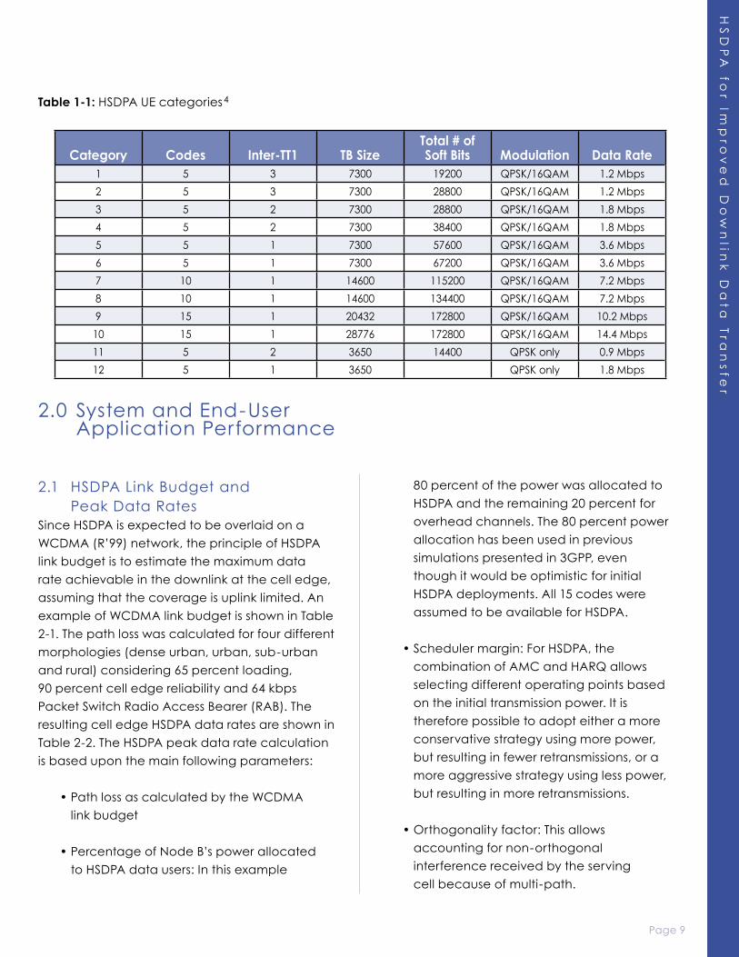
1.6 UE CapabilitiesTwelve new categories have been specified
by Release 5 for HSDPA UEs (see Table 1-1)
according to the following parameters:
• Maximum number of HS-DSCH multi-
codes that the UE can simultaneously
receive (five, 10 or 15).
• Minimum inter-TTI time, which defines the
minimum time between the beginning
of two consecutive transmissions to this
UE. If the inter-TTI time is one, this means
that the UE can receive HS-DSCH packets
during consecutive TTIs, i.e. every 2 ms.
If the inter-TTI time is two, the scheduler
would need to skip one TTI between
consecutive transmissions to this UE.
• Maximum number of HS-DSCH transport
block bits received within an HS-DSCH TTI.
The combination of this parameter and
the inter-TTI interval determines the UE
peak data rate. For example, the transport
block size and the inter-TTI interval for
category 11 are 3650 bits and 2 (or 4) ms.
This leads to a data rate of 0.9 Mbps.
• The maximum number of soft channel
bits over all the HARQ processes. This can
impact the UE receiver performance
particularly in poor quality locations
where the number of retransmissions can
be high. A UE with a low number of soft
channel bits will not be able to support
IR for the highest peak data rates and its
performance will thus be slightly lower
than for a UE supporting a larger number
of soft channels.
• Supported modulations (QPSK only
or both QPSK and 16QAM).
These 12 categories provide a much more
coherent set of capabilities as compared to R’99
which gives UE manufacturers freedom to use
completely atypical combinations.
Page 8
HS
DP
A f
or
Imp
rov
ed
Do
wn
lin
k D
ata
Tra
ns
fer
Page 9
HS
DP
A fo
r Imp
rov
ed
Do
wn
link
Da
ta T
ran
sfe
r
2.0 System and End-User Application Performance
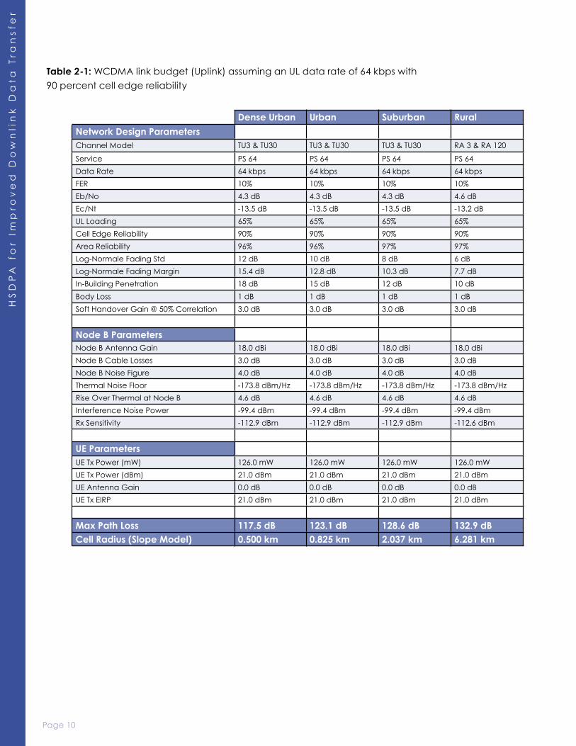
2.1 HSDPA Link Budget and Peak Data Rates
Since HSDPA is expected to be overlaid on a
WCDMA (R’99) network, the principle of HSDPA
link budget is to estimate the maximum data
rate achievable in the downlink at the cell edge,
assuming that the coverage is uplink limited. An
example of WCDMA link budget is shown in Table
2-1. The path loss was calculated for four different
morphologies (dense urban, urban, sub-urban
and rural) considering 65 percent loading,
90 percent cell edge reliability and 64 kbps
Packet Switch Radio Access Bearer (RAB). The
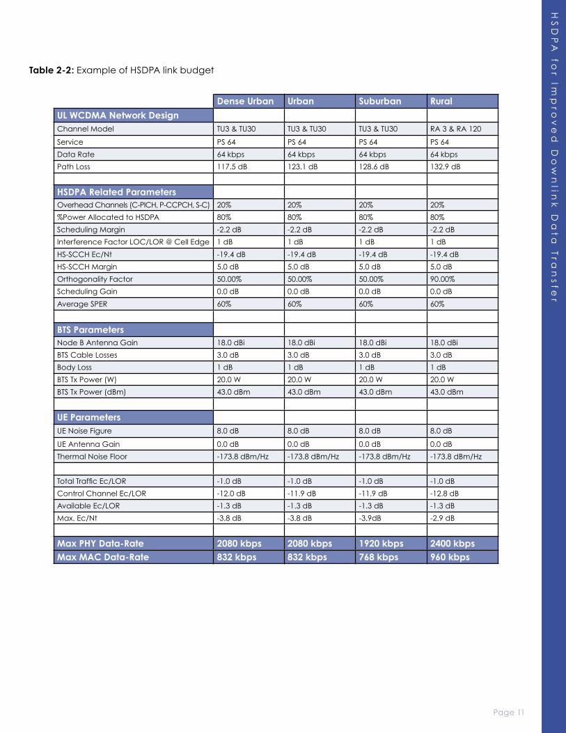
resulting cell edge HSDPA data rates are shown in
Table 2-2. The HSDPA peak data rate calculation
is based upon the main following parameters:
• Path loss as calculated by the WCDMA
link budget
• Percentage of Node B’s power allocated
to HSDPA data users: In this example
80 percent of the power was allocated to
HSDPA and the remaining 20 percent for
overhead channels. The 80 percent power
allocation has been used in previous
simulations presented in 3GPP, even
though it would be optimistic for initial
HSDPA deployments. All 15 codes were
assumed to be available for HSDPA.
• Scheduler margin: For HSDPA, the
combination of AMC and HARQ allows
selecting different operating points based
on the initial transmission power. It is
therefore possible to adopt either a more
conservative strategy using more power,
but resulting in fewer retransmissions, or a
more aggressive strategy using less power,
but resulting in more retransmissions.
• Orthogonality factor: This allows
accounting for non-orthogonal
interference received by the serving
cell because of multi-path.
Table 1-1: HSDPA UE categories4
Category Codes Inter-TT1 TB SizeTotal # of Soft Bits Modulation Data Rate
1 5 3 7300 19200 QPSK/16QAM 1.2 Mbps
2 5 3 7300 28800 QPSK/16QAM 1.2 Mbps
3 5 2 7300 28800 QPSK/16QAM 1.8 Mbps
4 5 2 7300 38400 QPSK/16QAM 1.8 Mbps
5 5 1 7300 57600 QPSK/16QAM 3.6 Mbps
6 5 1 7300 67200 QPSK/16QAM 3.6 Mbps
7 10 1 14600 115200 QPSK/16QAM 7.2 Mbps
8 10 1 14600 134400 QPSK/16QAM 7.2 Mbps
9 15 1 20432 172800 QPSK/16QAM 10.2 Mbps
10 15 1 28776 172800 QPSK/16QAM 14.4 Mbps
11 5 2 3650 14400 QPSK only 0.9 Mbps
12 5 1 3650 QPSK only 1.8 Mbps
Page 10
HS
DP
A f
or
Imp
rov
ed
Do
wn
lin
k D
ata
Tra
ns
fer
Page 11
HS
DP
A fo
r Imp
rov
ed
Do
wn
link
Da
ta T
ran
sfe
r
Table 2-1: WCDMA link budget (Uplink) assuming an UL data rate of 64 kbps with
90 percent cell edge reliability
Dense Urban Urban Suburban Rural
Network Design ParametersChannel Model TU3 & TU30 TU3 & TU30 TU3 & TU30 RA 3 & RA 120
Service PS 64 PS 64 PS 64 PS 64
Data Rate 64 kbps 64 kbps 64 kbps 64 kbps
FER 10% 10% 10% 10%
Eb/No 4.3 dB 4.3 dB 4.3 dB 4.6 dB
Ec/Nt -13.5 dB -13.5 dB -13.5 dB -13.2 dB
UL Loading 65% 65% 65% 65%
Cell Edge Reliability 90% 90% 90% 90%
Area Reliability 96% 96% 97% 97%
Log-Normale Fading Std 12 dB 10 dB 8 dB 6 dB
Log-Normale Fading Margin 15.4 dB 12.8 dB 10.3 dB 7.7 dB
In-Building Penetration 18 dB 15 dB 12 dB 10 dB
Body Loss 1 dB 1 dB 1 dB 1 dB
Soft Handover Gain @ 50% Correlation 3.0 dB 3.0 dB 3.0 dB 3.0 dB
Node B ParametersNode B Antenna Gain 18.0 dBi 18.0 dBi 18.0 dBi 18.0 dBi
Node B Cable Losses 3.0 dB 3.0 dB 3.0 dB 3.0 dB
Node B Noise Figure 4.0 dB 4.0 dB 4.0 dB 4.0 dB
Thermal Noise Floor -173.8 dBm/Hz -173.8 dBm/Hz -173.8 dBm/Hz -173.8 dBm/Hz
Rise Over Thermal at Node B 4.6 dB 4.6 dB 4.6 dB 4.6 dB
Interference Noise Power -99.4 dBm -99.4 dBm -99.4 dBm -99.4 dBm
Rx Sensitivity -112.9 dBm -112.9 dBm -112.9 dBm -112.6 dBm
UE ParametersUE Tx Power (mW) 126.0 mW 126.0 mW 126.0 mW 126.0 mW
UE Tx Power (dBm) 21.0 dBm 21.0 dBm 21.0 dBm 21.0 dBm
UE Antenna Gain 0.0 dB 0.0 dB 0.0 dB 0.0 dB
UE Tx EIRP 21.0 dBm 21.0 dBm 21.0 dBm 21.0 dBm
Max Path Loss 117.5 dB 123.1 dB 128.6 dB 132.9 dBCell Radius (Slope Model) 0.500 km 0.825 km 2.037 km 6.281 km
Page 10
HS
DP
A f
or
Imp
rov
ed
Do
wn
lin
k D
ata
Tra
ns
fer
Page 11
HS
DP
A fo
r Imp
rov
ed
Do
wn
link
Da
ta T
ran
sfe
r
Table 2-2: Example of HSDPA link budget
Dense Urban Urban Suburban Rural
UL WCDMA Network DesignChannel Model TU3 & TU30 TU3 & TU30 TU3 & TU30 RA 3 & RA 120
Service PS 64 PS 64 PS 64 PS 64
Data Rate 64 kbps 64 kbps 64 kbps 64 kbps
Path Loss 117.5 dB 123.1 dB 128.6 dB 132.9 dB
HSDPA Related ParametersOverhead Channels (C-PICH, P-CCPCH, S-C) 20% 20% 20% 20%
%Power Allocated to HSDPA 80% 80% 80% 80%
Scheduling Margin -2.2 dB -2.2 dB -2.2 dB -2.2 dB
Interference Factor LOC/LOR @ Cell Edge 1 dB 1 dB 1 dB 1 dB
HS-SCCH Ec/Nt -19.4 dB -19.4 dB -19.4 dB -19.4 dB
HS-SCCH Margin 5.0 dB 5.0 dB 5.0 dB 5.0 dB
Orthogonality Factor 50.00% 50.00% 50.00% 90.00%
Scheduling Gain 0.0 dB 0.0 dB 0.0 dB 0.0 dB
Average SPER 60% 60% 60% 60%
BTS ParametersNode B Antenna Gain 18.0 dBi 18.0 dBi 18.0 dBi 18.0 dBi
BTS Cable Losses 3.0 dB 3.0 dB 3.0 dB 3.0 dB
Body Loss 1 dB 1 dB 1 dB 1 dB
BTS Tx Power (W) 20.0 W 20.0 W 20.0 W 20.0 W
BTS Tx Power (dBm) 43.0 dBm 43.0 dBm 43.0 dBm 43.0 dBm
UE ParametersUE Noise Figure 8.0 dB 8.0 dB 8.0 dB 8.0 dB
UE Antenna Gain 0.0 dB 0.0 dB 0.0 dB 0.0 dB
Thermal Noise Floor -173.8 dBm/Hz -173.8 dBm/Hz -173.8 dBm/Hz -173.8 dBm/Hz
Total Traffic Ec/LOR -1.0 dB -1.0 dB -1.0 dB -1.0 dB
Control Channel Ec/LOR -12.0 dB -11.9 dB -11.9 dB -12.8 dB
Available Ec/LOR -1.3 dB -1.3 dB -1.3 dB -1.3 dB
Max. Ec/Nt -3.8 dB -3.8 dB -3.9dB -2.9 dB
Max PHY Data-Rate 2080 kbps 2080 kbps 1920 kbps 2400 kbpsMax MAC Data-Rate 832 kbps 832 kbps 768 kbps 960 kbps

Page 12
HS
DP
A f
or
Imp
rov
ed
Do
wn
lin
k D
ata
Tra
ns
fer
Page 13
HS
DP
A fo
r Imp
rov
ed
Do
wn
link
Da
ta T
ran
sfe
r
The link budget estimates the user’s channel
quality (i.e. Ec/Nt) that is then mapped to the
maximum achievable physical layer (PHY) data
rate (adjusted for RLC overhead). The MAC level
data rate accounts for HARQ retransmissions.
Table 2-2 indicates that for 80 percent power
allocation to HSDPA and two retransmissions per
transport block (typical value), the possible peak
data rate at the cell edge for a single user can
reach 2 Mbps at the physical layer and 800 kbps
at the MAC layer. This represents an impressive
improvement over what R’99 can offer at the cell
edge. In an actual loaded system, HSDPA user
data rates can be at least three times higher than
what one can get with the currently deployed
WCDMA networks. It is important to note,
however, that the peak data rate calculation
does not reflect any time-multiplexing,
scheduling strategy or UE code capabilities.
It simply estimates the maximum data rate that
a user can get if all the Node B resources (power
and codes) are available.
As mentioned before, the obtained data rates
strongly depend on the percentage of power
allocated to HSDPA users and Eb/N0. Since HSDPA
and R’99 channels may operate on the same
frequency (at least in early deployment phases),
the power sharing becomes an important issue
for WCDMA (UMTS) operators. A good trade-off
between voice capacity, data sector throughput
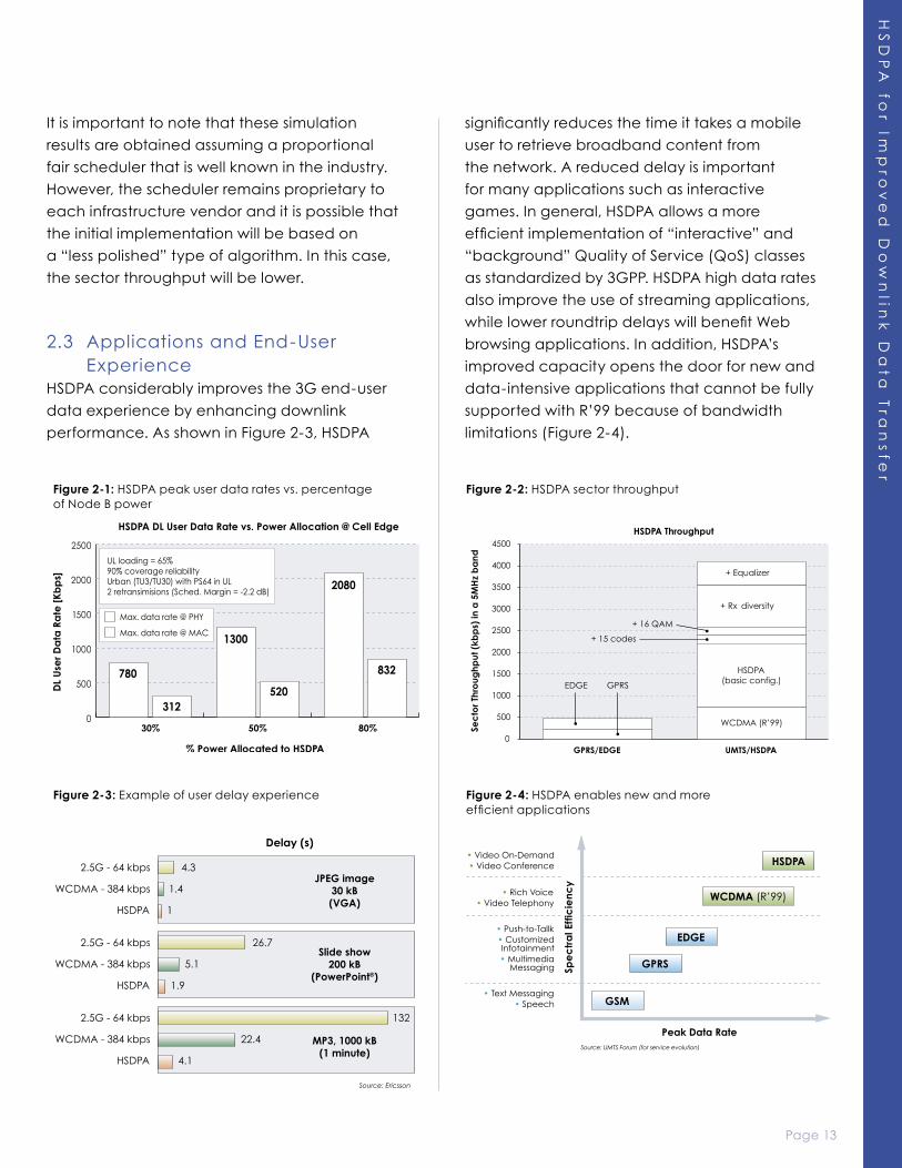
and offered data rates must be found. Figure 2-1
illustrates the impact of HSDPA power allocation
on the achievable data rates at the cell edge.
It is clear that the highest data rates will be
obtained when HSDPA is deployed on a separate
frequency. Additional simulations have also
shown that the average user throughput across
the sector decreases linearly with the percentage
of Node B power allocated to HSDPA.
2.2 HSDPA Sector ThroughputThe HSDPA sector throughput depends on many
parameters, such as Node B system loading,
Node B scheduler algorithm, UE capabilities,
traffic usage, percentage of power allocated
to HSDPA, radio environment (i.e. channel model)
and the network layout. Several simulations have
been performed by QUALCOMM to estimate
the HSDPA sector throughput and its sensitivity
to some of the above parameters. It was found
that for a typical outdoor urban environment
(assuming 75 percent of the users are static or
pedestrian and 25 percent are vehicular at
30 km/h), the average sector throughput is 1.8
to 2.2 Mbps for the basic configuration (five
codes UE capability, QPSK only and no receive
diversity). This result is based on a Proportional Fair
scheduler, a full-buffer traffic model and
a dedicated HSDPA frequency with 80 percent
power for HSDPA users (i.e. 20 percent overhead
channels). This corresponds to an almost 200
percent improvement over WCDMA R’99
(700-800 kbps) and 350 percent over EGPRS*.
As shown in Figure 2-2, the sector throughput
increases with the UE capabilities. In fact,
15-code capability can improve the sector
throughput by an average of 10 percent, while
16QAM modulation can add another six percent
to eight percent. Receive diversity, if used, can
bring 40 to 55 percent improvement resulting in
a sector throughput of 3.2 to 3.6 Mbps. Note that
the receive diversity gains derive from internal
simulations assuming equal antenna gains
and no envelope correlation between the two
antennas. In reality, the expected gains might
be lower depending on the antenna gain
difference (between the primary and the
secondary antenna) and the envelope
correlation coefficient.
The use of equalization is also expected to further
improve the sector throughput by an additional
15 to 25 percent.
* 480 kbps assuming all coding schemes (MCS1-9) and up to four time slots
Page 12
HS
DP
A f
or
Imp
rov
ed
Do
wn
lin
k D
ata
Tra
ns
fer
Page 13
HS
DP
A fo
r Imp
rov
ed
Do
wn
link
Da
ta T
ran
sfe
r
It is important to note that these simulation
results are obtained assuming a proportional
fair scheduler that is well known in the industry.
However, the scheduler remains proprietary to
each infrastructure vendor and it is possible that
the initial implementation will be based on
a “less polished” type of algorithm. In this case,
the sector throughput will be lower.
2.3 Applications and End-User Experience
HSDPA considerably improves the 3G end-user
data experience by enhancing downlink
performance. As shown in Figure 2-3, HSDPA
significantly reduces the time it takes a mobile
user to retrieve broadband content from
the network. A reduced delay is important
for many applications such as interactive
games. In general, HSDPA allows a more
efficient implementation of “interactive” and
“background” Quality of Service (QoS) classes
as standardized by 3GPP. HSDPA high data rates
also improve the use of streaming applications,
while lower roundtrip delays will benefit Web
browsing applications. In addition, HSDPA’s
improved capacity opens the door for new and
data-intensive applications that cannot be fully
supported with R’99 because of bandwidth
limitations (Figure 2-4).
Figure 2-2: HSDPA sector throughput
Figure 2-3: Example of user delay experience Figure 2-4: HSDPA enables new and more efficient applications
Figure 2-1: HSDPA peak user data rates vs. percentage of Node B power
Page 14
HS
DP
A f
or
Imp
rov
ed
Do
wn
lin
k D
ata
Tra
ns
fer
Page 15
HS
DP
A fo
r Imp
rov
ed
Do
wn
link
Da
ta T
ran
sfe
r
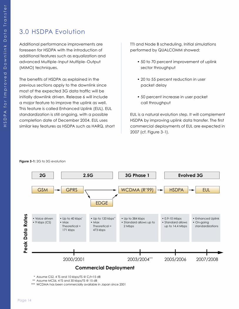
3.0 HSDPA Evolution
Additional performance improvements are
foreseen for HSDPA with the introduction of
additional features such as equalization and
advanced Multiple-Input Multiple-Output
(MIMO) techniques.
The benefits of HSDPA as explained in the
previous sections apply to the downlink since
most of the expected 3G data traffic will be
initially downlink driven. Release 6 will include
a major feature to improve the uplink as well.
This feature is called Enhanced Uplink (EUL). EUL
standardization is still ongoing, with a possible
completion date of December 2004. EUL uses
similar key features as HSDPA such as HARQ, short
TTI and Node B scheduling. Initial simulations
performed by QUALCOMM showed:
• 50 to 70 percent improvement of uplink
sector throughput
• 20 to 55 percent reduction in user
packet delay
• 50 percent increase in user packet
call throughput
EUL is a natural evolution step. It will complement
HSDPA by improving uplink data transfer. The first
commercial deployments of EUL are expected in
2007 (cf. Figure 3-1).
Figure 3-1: 2G to 3G evolution
Page 14
HS
DP
A f
or
Imp
rov
ed
Do
wn
lin
k D
ata
Tra
ns
fer
Page 15
HS
DP
A fo
r Imp
rov
ed
Do
wn
link
Da
ta T
ran
sfe
r
4.0 Networks Economics
In the previous sections, it has been shown
that adding HSDPA into an operator’s wireless
network provides for the delivery of higher sector
and user throughputs along with lower user
latencies. These improvements in the delivery
of data will enable operators to provide a host
of new compelling and content rich services
and applications. In this section, the cost of
delivering data will be examined and it will be
shown how the introduction of HSDPA can help
operators to significantly reduce the cost of
providing data services. By delivering low cost,
content rich applications, operators will be able
to differentiate their services, create brand loyalty
and grow their data revenue and margins
per subscriber.
The cost of delivering data (the network expense)
is defined as the sum of the network operating
expense and capital depreciation. The network
expense is driven largely by the aggregate
sector throughput of a base station. Assuming
constant per site costs, the more megabytes that
can be driven through a site (from higher sector
throughputs) the lower the cost of delivering
each megabyte. Thus the HSDPA improvements
in spectral efficiency result in lower per Megabyte
(MB) delivery costs compared to EDGE and
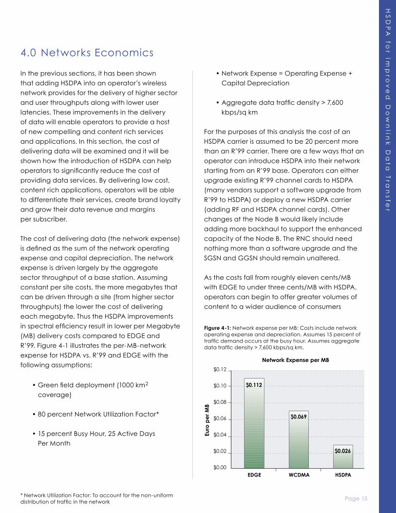
R’99. Figure 4-1 illustrates the per-MB-network
expense for HSDPA vs. R’99 and EDGE with the
following assumptions:
• Green field deployment (1000 km2
coverage)
• 80 percent Network Utilization Factor*
• 15 percent Busy Hour, 25 Active Days
Per Month
• Network Expense = Operating Expense +
Capital Depreciation
• Aggregate data traffic density > 7,600
kbps/sq km
For the purposes of this analysis the cost of an
HSDPA carrier is assumed to be 20 percent more
than an R’99 carrier. There are a few ways that an
operator can introduce HSDPA into their network
starting from an R’99 base. Operators can either
upgrade existing R’99 channel cards to HSDPA
(many vendors support a software upgrade from
R’99 to HSDPA) or deploy a new HSDPA carrier
(adding RF and HSDPA channel cards). Other
changes at the Node B would likely include
adding more backhaul to support the enhanced
capacity of the Node B. The RNC should need
nothing more than a software upgrade and the
SGSN and GGSN should remain unaltered.
As the costs fall from roughly eleven cents/MB
with EDGE to under three cents/MB with HSDPA,
operators can begin to offer greater volumes of
content to a wider audience of consumers
Figure 4-1: Network expense per MB: Costs include network operating expense and depreciation. Assumes 15 percent of traffic demand occurs at the busy hour. Assumes aggregate data traffic density > 7,600 kbps/sq km.
* Network Utilization Factor: To account for the non-uniform distribution of traffic in the network
Page 16
HS
DP
A f
or
Imp
rov
ed
Do
wn
lin
k D
ata
Tra
ns
fer
Page 17
HS
DP
A fo
r Imp
rov
ed
Do
wn
link
Da
ta T
ran
sfe
r
at lower prices. A comparison can be made
to the migration of wireless voice service from
analog to digital. With analog service the cost to
provide a minute of voice service was relatively
high; this high cost limited the penetration of
the wireless market and the number of minutes
per month subscribers could afford to talk. With
the introduction of digital wireless voice services
the cost of providing a minute of talk time came
down dramatically. The lower cost structure
brought reduced pricing plans, making the
service affordable to a wider audience
and enabling wireless penetration and usage
to climb.
As mentioned previously, with the introduction of
HSDPA operators will be able to provide a wide
range of compelling applications and services.
In particular, there is a growing demand for
content rich media services such as video on
demand, audio on demand, picture/video
messaging and location-based services. The
spectral efficiency advantages of HSDPA will
enable operators to deliver these services at
lower costs and with a better user experience
than legacy technologies. The introduction of
HSDPA can also open up other business segments
to the operator. Services the operator may wish
to consider include high-speed laptop access for
the enterprise and consumer segments, and the
introduction of fixed wireless broadband access
in regions where cable and DSL offerings may not
be able to reach.
5.0 Conclusion
HSDPA provides impressive enhancements over
WCDMA R’99 for the downlink. It offers peak data
rates of up to 10 Mbps, resulting in a better end-
user experience for downlink data applications
(shorter connection and response times). More
importantly, HSDPA offers three- to five-fold sector
throughput increase, which results in significantly
more data users on a single frequency. HSDPA
higher throughputs and peak data rates will help
stimulate and drive up consumption of data
intensive applications that cannot be supported
by R’99. In fact, HSDPA allows a more efficient
implementation of interactive and background
Quality of Service (QoS) classes as standardized
by 3GPP. HSDPA high data rates improve the use
of streaming applications, while lower roundtrip
delays will benefit Web browsing applications.
Another important benefit of HSDPA is its
backwards compatibility with R’99. This makes
its deployment very smooth and gradual on an
“as needed” basis.
The deployment of HSDPA is very cost effective
since the incremental cost is mainly due to Node
Bs and RNC upgrades. In a capacity-limited
environment, the network cost to deliver a
megabyte of data traffic is three cents for a
typical dense urban environment, as opposed
to seven cents for R’99 (assuming an incremental
cost of 20 percent).
The ability to offer higher peak rates for an
increasingly performance demanding end-
user at a substantially lower cost will create
a significant competitive advantage for
HSDPA operators. Supporting rich multimedia
applications and content and more compelling
devices at lower user cost will drive higher
traffic per user and will enable early movers to
differentiate themselves with advanced services
— increasing their subscriber growth, data market
share and profitability.
Page 16
HS
DP
A f
or
Imp
rov
ed
Do
wn
lin
k D
ata
Tra
ns
fer
Page 17
HS
DP
A fo
r Imp
rov
ed
Do
wn
link
Da
ta T
ran
sfe
r
6.0 References
1. 3GPP TS25.211, “Physical Channels and Mapping of Transport Channels onto Physical
Channels (FDD),” version 5.5.0.
2. 3GPP TS25.855, “High Speed Downlink Packet Access; Overall UTRAN Description,”
version 5.0.0.
3. 3GPP TS25.308, “UTRA High Speed Downlink Packet Access (HSDPA); Overall description;
Stage 2,” version 5.5.0.
4. 3GPP TS25.306, “UE Radio Access Capabilities Definition,” version 5.8.0.
5. Troels E. Kolding et al., “High Speed Downlink Packet Access: WCDMA Evolution,”
IEEE Vehicular Technology Society News, pp. 4-10, February 2003.
6. Stephan Parkvall et al., “WCDMA evolved -High speed packet data services,”
Ericsson Review No. 2, 2003, pp. 56-65.
7. Hari Holma and Antti Toscala, “WCDMA for UMTS,” edited at Wiley & Sons, Ltd, 2002.
8. K. W. Helmersson and G. Bark, “Performance of Downlink Shard Channels in WCDMA Radio
Networks,” Proc. IEEE Vehicular Technology Conference (VTC), vol. 4,
pp-2690-2694, Spring 2001.
9. M. Chatterjee, G.D. Mandyam, S.K. Das. “Fast ARQ in High Speed Downlink Packet Access
for WCDMA Systems,” Proc. Of European Wireless, pp 451-457, Feb. 2002.
10. 3GPP TR 25.896, “Feasibility Study for Enhanced Uplink for UTRA FDD (Release 6),” v6.0.0.
11. QUALCOMM white paper, “The Economics of Mobile Wireless Data.”