White Paper UEFI Plugfest 2015 - Challenges for UEFI and the Cloud
35
i White Paper UEFI Plugfest 2015 - Challenges for UEFI and the Cloud Mallik Bulusu Microsoft Corporation Vincent Zimmer Intel Corporation May 2015
Transcript of White Paper UEFI Plugfest 2015 - Challenges for UEFI and the Cloud

i
White Paper
UEFI Plugfest 2015 - Challenges for
UEFI and the Cloud
Mallik Bulusu
Microsoft Corporation
Vincent Zimmer
Intel Corporation
May 2015

ii
Executive Summary
This paper talks about the challenges for Cloud computing. The Open Compute Project
(OCP) [OCP] vies to provide interoperability between many elements in the data center,
pioneering ‘open hardware’ precepts for this market area.
Just as the OCP goal is to have interoperability between all elements of the server complex,
UEFI [UEFI-BOOK] attempts to provide similar business interoperability. Specifically,
the UEFI/PI/ACPI designs have followed the same spirit, effecting this intent through
industry standard API’s. Through these API’s we can have plug and play binaries between
different business elements.
UEFI can help open up the boot and management firmware elements of OCP that have
traditionally been vendor specific and not fully interoperable.
This paper isn’t exhaustive but instead attempts to highlight some Cloud challenges with
corresponding solutions based upon UEFI.
Prerequisite:
This paper assumes that audience has basic EDKII/UEFI firmware development
experience.

iii
Table of Contents
Cloud Firmware Challenges .................................................................................................. 4
Firmware Update.................................................................................................................... 10
.............................................................................................................................................. 13
Bare Metal Provisioning ....................................................................................................... 14
Introduction ......................................................................................................................... 14
Processor Architecture Types .............................................................................................. 19
Security ..................................................................................................................................... 22
Attack climate ..................................................................................................................... 22
Tools and Diagnostics .......................................................................................................... 26
Introduction ......................................................................................................................... 26
Conclusion ................................................................................................................................ 29
Glossary .................................................................................................................................... 30
References ................................................................................................................................ 32

4
Cloud Firmware Challenges
Introduction – the Cloud When designing a compute engine, one must strive to work around three main constraints, as
shown in below Figure, namely –
Constraints from Physics
How to deploy the compute engine?
How to manage the compute?
Figure: Challenge Vectors
Hypothetically, let us imagine possibility of an ideal compute node that can cater to all the
conceivable compute in the universe. This will simply trivialize the deployment challenges as we
have to prepare the hardware once. Then we have to install the firmware stack, OS and software
stack exactly once. But this is clearly not viable from the viewpoint of performing compute as
there are power delivery challenges, thermal, mechanical and availability challenges etc. The
Cloud [CLOUD] server paradigm offers elegant answer to this problem via its inherent scale. In
particular, it addresses various challenges such as power deliver, thermal, mechanical, availability,
etc. associated with concentration of compute. This is accomplished by distribution of compute
across thousands of compute nodes. Such compute nodes are usually symmetric, but that is not a
requirement. The advantage of cloud paradigm is that with varying compute needs, the size of
Cloud can be changed accordingly. However, this does pose new challenges related to “deploying”
the compute as well as “managing” the compute, such as–
ensuring that firmware updates can be deployed seamlessly on a broad scale
ensuring that cloud can be provisioned seamlessly as per underlying specifications
ensuring that cloud is secured both at a node level as well as at datacenter/cloud level
ensuring that software tools and diagnostics can easily predict and/or detect, root-cause failures

5
This paper examines the opportunities and challenges that lie ahead with the UEFI, in order to
solve above platform construction problems via standards.
Introduction – UEFI UEFI stands for the “Unified Extensible Firmware Interface.” UEFI has several dimensions,
including industry standards [UEFI] for purposes of interoperability between operating system
loaders, pre-OS applications, and operating system runtimes. The UEFI Forum governs the UEFI
Specification evolution and various companies, including Intel ®, contribute to the open source
project.
The salient details of the UEFI specification includes the definition of ANSI C-callable API’s that
are published by the system board firmware implementation. The figure below describes various
facets of UEFI, including the dynamically loadable UEFI drivers that can be installed on host-bus
adapters (HBA’s). This allows for moving beyond the limitations of PC/AT BIOS wherein option
ROM’s had to reside in a fixed location. The UEFI Specification defines a set of mandatory
capabilities, including boot and runtime services. These services allow for managing memory,
timers, events, UEFI variables, capsules, and loading code. Beyond those basic services, chapter
2.6 of the UEFI 2.4 Specification describes the mandatory and optional services. To be a compliant
UEFI implementation, you don’t need much more than the boot services, runtime services, and
loadfile protocol.
In addition to the API’s, the C-callable nature of the UEFI specification allows for platform and
CPU architecture flexibility. As of writing this document, the UEFI specification support Intel 32-
bit and 64-bit architecture, Intel Itanium ®, and ARM Ltd ® 32-bit and 64-bit CPU’s. There are
some open source ports to other architectures, such as MIPS ® 32-bit, but they do not have an
official binding in the specification. The reason for the binding is that it allows for interoperability
between components built but different entities, from the system board vendors, sometimes known
as the Original Equipment Manufacturer (OEM) or Original Device Manufacturer (ODM).
Leading to the consumers of UEFI services, such as 3rd party UEFI driver extension from an
Independent Hardware Vendor (IHV). And finally, there are pre-OS independent software
vendors (ISV’s) and the hypervisor or operating system vendors. We will club the latter two
together as “OSV’s” since for purposes of the boot firmware there is no distinction between a
virtual machine monitor, such as a type1 VMM or hypervisor, and a static OS. UEFI services can
be published by the bare metal motherboard or from within the hypervisor, such as in the case of
‘guest firmware.’
Another aspect of UEFI includes the GUIDed Partition Table (GPT). The GPT breaks away from
today’s MBR and allows for breaking the 2 Terabyte disk limit. Strictly speaking the GPT
definition can be used outside of platforms with underlying UEFI firmware implementations, too.
The figure below also highlights other capabilities of UEFI, including the ‘UEFI Secure Boot’
feature. More will be discussed about this capability, but the gist of the feature is to allow some
administrative control of the extensible image loading found in UEFI. And what is potentially of
interest to the cloud community includes the integrated networking capability of UEFI, along with
a shell. In the spirit of the design-by-interface methodology of UEFI, these API’s for all of the

6
underlying networking interfaces, from the IHV-supplied lowest level wired networking driver up
to the software-visible API’s that correspond to the OSI stack, can all be found in the main UEFI
Specification document. Correspondingly, the UEFI Shell has a specification hosted on [UEFI],
too, alongside the main UEFI Specification. This mapping to documentation allows for
interoperability and investment protection of applications that consume the network stack, shell
script, and shell [UEFI-SHELL] applications, respectively.
In addition to the main UEFI specification, though, there is an open source reference
implementation [EDK2]. Although the UEFI Forum does not officially endorse any specific
implementation, the community has historically attempted to produce a reference implementation
of the standard publically available along with the document production. As such, the figure below
show how each version of the specification at the top has a corresponding implementation
underneath. The underlying software technology used to build these implementations have
evolved, from the EFI Development Kit (EDK) of the early UEFI Specifications to the present
EDK II project.

7

8
Speaking of EDK II, this is an open source implementation of the various specifications hosted on
[EDK2]. Diagrammatically, the figure below shows the various facets of this project. It provides
implementations of the UEFI specifications, the underlying Platform Initialization (PI)
specifications, and the Advanced Configuration and Power Interface (ACPI) specification.

9
The open source has full implementations of the UEFI core elements, industry standard bus and
class drivers, such as PCI, USB, SATA.
Summary
The Cloud poses many challenges for platform construction. Given the many business entities
involved in deploying the Cloud, from OEM to IHV to ISV to OSV, the ability of UEFI to provide
interoperability between the parties bears exploration. The following sections will provide a short,
albeit incomplete, map into that exploration.

10
Firmware Update
Introduction
The cloud platform comprises of various hardware elements such as CPUs, chipset, BMC, ME,
on-board PCI devices, add-on PCI devices, storage devices, FPGA based platform extensions etc.
as shown in Figure 2. Often, there is an associated firmware stack associated with each of these
hardware elements. Thus, in addition to System BIOS which is responsible for booting the
platform, host of other firmware elements must be programmed and maintained throughout the life
of a platform. In addition, cloud paradigm necessitates voluminous deployment of compute nodes
housed within a datacenter.
Figure 2: Firmware Composition Challenge
The updateable firmware ingredients can be broadly classified into two categories, viz. system
firmware and device firmware. A system firmware is one which is mandatory platform ingredient
without which booting of the system is not possible. On the contrary, the device firmware relates
to any firmware ingredient that is not required in order to successfully boot the platform. Examples
of system firmware include UEFI/BIOS, BMC firmware, ME firmware etc. Examples of device
firmware include SSD firmware, RAID firmware etc.

11
The firmware update process involves three key steps, viz. –
1) verifying the firmware binary integrity
2) updating the firmware
3) verifying update is successful or preform a rollback
These steps are shared by all firmware updates, irrespective of type of the firmware. Refer to
Figure 3 for a high level flow chart describing key steps of firmware update.
Start
Check Capsule Integrity
Is check successful?
Reject Capsule
Update firmware
Is Update successful?
Verify Update
Retry Update
Is update successful?
Rollback
End
No
No
No
Yes
Yes
Yes
Figure 3: Typical Firmware Update Flow
12
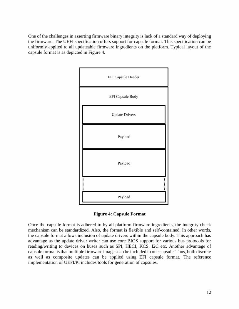
One of the challenges in asserting firmware binary integrity is lack of a standard way of deploying
the firmware. The UEFI specification offers support for capsule format. This specification can be
uniformly applied to all updateable firmware ingredients on the platform. Typical layout of the
capsule format is as depicted in Figure 4.
Figure 4: Capsule Format
Once the capsule format is adhered to by all platform firmware ingredients, the integrity check
mechanism can be standardized. Also, the format is flexible and self-contained. In other words,
the capsule format allows inclusion of update drivers within the capsule body. This approach has
advantage as the update driver writer can use core BIOS support for various bus protocols for
reading/writing to devices on buses such as SPI, HECI, KCS, I2C etc. Another advantage of
capsule format is that multiple firmware images can be included in one capsule. Thus, both discrete
as well as composite updates can be applied using EFI capsule format. The reference
implementation of UEFI/PI includes tools for generation of capsules.
EFI Capsule Header
EFI Capsule Body
Update Drivers
Payload
Payload
Payload
13
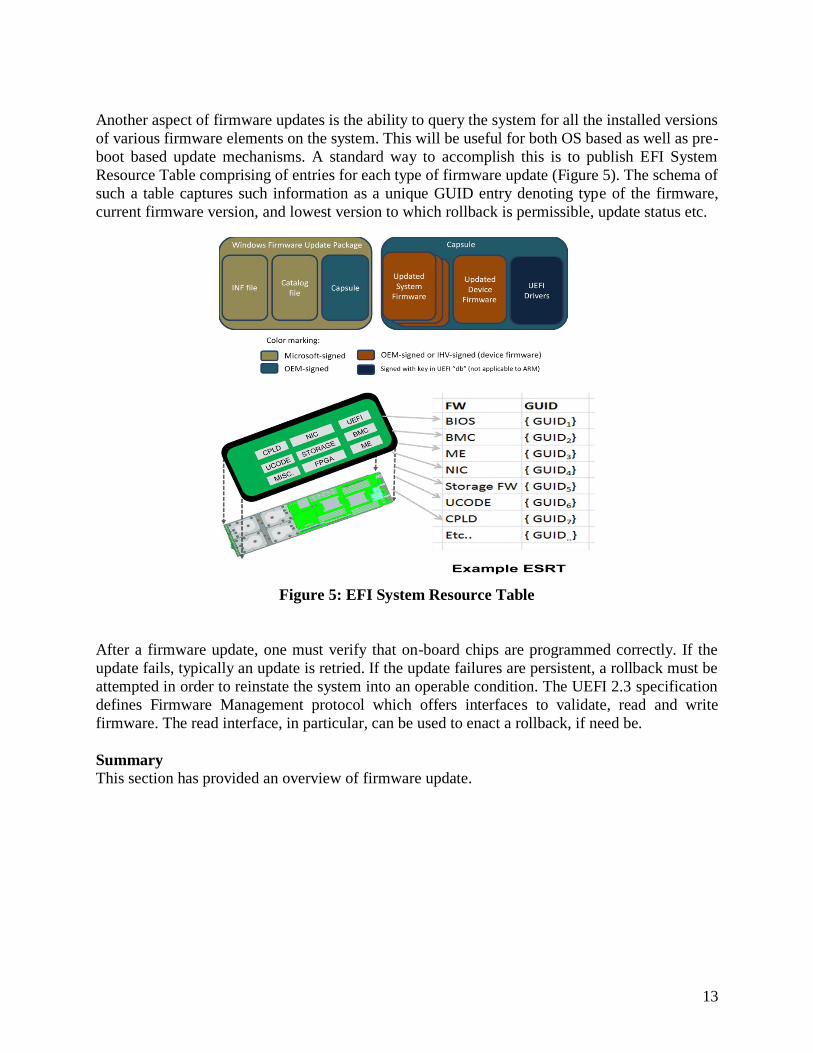
Another aspect of firmware updates is the ability to query the system for all the installed versions
of various firmware elements on the system. This will be useful for both OS based as well as pre-
boot based update mechanisms. A standard way to accomplish this is to publish EFI System
Resource Table comprising of entries for each type of firmware update (Figure 5). The schema of
such a table captures such information as a unique GUID entry denoting type of the firmware,
current firmware version, and lowest version to which rollback is permissible, update status etc.
Figure 5: EFI System Resource Table
After a firmware update, one must verify that on-board chips are programmed correctly. If the
update fails, typically an update is retried. If the update failures are persistent, a rollback must be
attempted in order to reinstate the system into an operable condition. The UEFI 2.3 specification
defines Firmware Management protocol which offers interfaces to validate, read and write
firmware. The read interface, in particular, can be used to enact a rollback, if need be.
Summary This section has provided an overview of firmware update.

14
Bare Metal Provisioning
This section will give an overview of bare metal provisioning.
Introduction
As shown in the figure below, the Cloud and warehouse-scale computes poses unique challenges
for platform deployment. These challenges include how to detect the hardware, how to coordinate
installation between an OEM system board and OSV operating system, configuring the system
board, cloning the server so that an image can be mass-deployed to thousands of machines, and
backing up settings in case of having to recover or re-deploy a machine. Given the scale of the
machines, these tasks should be automated since having a user in front of each machine to do
manual configuration is not economic.
The platform firmware has integral roles in provisioning. Whether it is the installation of an
operating system during the factory or repurposing a data center, UEFI has many elements that
come into play. There is the boot-strapping problem of how to get the OS or hypervisor onto the
system board, or the chick-and-the-egg problem. UEFI was designed to allow for ease of OS
installation and multi-booting. The mechanism put in place with UEFI provides a software
environment for installation agents and OS loaders includes supplying mechanism to orchestrate
discovery of boot code, managing policy of ‘from where to boot’ and ‘which console to use’ via
the UEFI variables.

15
The bare metal provisioning scenarios where UEFI comes into play. For purposes of no touch
automated installation, the UEFI Forum is now the maintainer of standards based network boot,
such as PXE. PXE is both a wire protocol and API’s. The API’s to support IPV4, TFTP-based
PXE can be found in the UEFI specification, and UEFI has also evolved those API’s and the wire
protocol to include IPV6. One key element of this evolution is RFC 5970 where the DHCP-based
discovery of PXE has been extended to go from a file path to a URI. 5970 allowed for a
discoverable IPV4 or IPV6 network boot to become:
‘iscsi://address/bootfilename.efi’
‘tftp://address/….’
Or HTTP. Or NFS. More information can be found at [UEFI-NETBOOT-BLOG].
This allows for evolving the boot experience, especially as there have been historical scaling issues
and timeouts with connectionless protocols like UDP-based TFTP. Connection oriented platforms
based upon TCP offer the future for scaling the network deployment of these large server
deployments.
The UEFI specification provides blocking and non-blocking local block storage and networking
API’s to allow for high performance provisioning actions, such as reading an OS image from the
network, overlapping I/O with compute like decompression, and writing to the local system board storage.
In addition, UEFI provides a very stylized means of configuration. [UEFI-CONFIG] describes some
of the usages of the Human Interface Infrastructure (HII), which is a forms-based mechanism for
configuration. Think of this as a richer variant of PC/AT BIOS CMOS settings. HII allows for
having a set of internationalized questions or strings with corresponding settings in a binary format
called IFR. HII forms can be presented by the system board for the equivalent of today’s set, and
the IHV drivers can also post HII. This allows for interoperable configuration. The forms also
allow for scripting and cloning.
Finally, UEFI allows for mandatory persistent storage in the platform by way of the UEFI Variable
interface. UEFI variables include mandatory elements to describe the boot policy, language, and
settings. The authenticated variables include the ability to have owner control of updates via
asymmetric cryptography. The binary encoding and storage medium of variables is not dictated
by the specification, so options include local SPI NOR flash, BMC’s, or other durable, protected
stores in the system board.
More information on Authenticated Variables can be found in the “UEFI Networking and Pre-OS
Security” paper [UEFI-ITJ].

16
Below is a figure depicting the implementation of the network stack in UEFI. In addition, [UEFI-
NET] provides a historical overview of the UEFI network stack.
Figure: Network Stack in UEFI

17
The UEFI specification defines API’s for both IPV4 and IPV6 networking. Other elements include
VLAN, IPsec, ISCSI, TCP, and UDP. These API’s are for pre-OS applications, such as
deployment agents, OS loaders, and pre-OS applications. The UEFI specification also defines
some wire protocols, such as netboot6, as the UEFI owns evolution of PXE.
With the advent of UEFI2.5, the network boot experience was expanded. Specifically, the
connectionless nature of today’s PXE and netboot6, namely TFTP based upon UDP, led to scaling
issues and time-outs. Non-standard based solutions [IPXE] started to prevail, thus the need for a
standards-based approach. Enter UEFI2.5, PI1.4, and ACPI6.0.
Although I cannot hope to do this topic justice in this paper, below are some details on
PI1.4 specification, ACPI6.0, and
UEFI2.5, as described in the press release [UEFI-PRESS].
These specifications tie into the above discussion via a few threads. One thread is the need to
evolve UEFI technology for the cloud, and to that end the boot-from-HTTP portion of the UEFI
2.5 specification squarely targets this space. Below shows schematically model of booting
wherein TFTP (and thus UDP) based PXE can move to HTTP (and thus TCP) based booting.
The move to a connection oriented protocol removes some of the chronic data center complaints,
such as time-outs in "booting the Skynet" [SKYNET], or more formally, provisioning
warehouse-scale computers [CLUSTER].
In addition to the wire protocols and DHCP extensions, additional API's for the network boot
program were created, such as HTTP, DNS, and TLS. The latter allows for an optional boot-
from-HTTP-s flow. This solution also allows for in-band and out-of-band RESTful [REST]
messaging, such as required by emergent management interfaces [REDFISH]. Although many
data centers use dark fibre and don't have threat models beyond the integrity concerns mitigated
by UEFI Secure Boot [UEFI-ITJ], TLS allows for confidentiality cover where deemed necessary.

18
And TLS comes more into play in order to support another scenario enabled by the UEFI 2.5
specification, namely boot-from-wifi. Wi-Fi security requires a supplicant, which is typically
EAP-TLS support. So the UEFI 2.5 specification updated EAP to work on concert with TLS for
the WI-FI use case. Some of the WI-FI support is shown below.
In addition to WIFI, Bluetooth support was also added to the UEFI 2.5 specification. This allows
for building IOT-style usages in UEFI, but more importantly works in tandem with WIFI above
for the no-wires style usages found in today's phone, tablets, and slim laptops. Without this
wireless evolution, UEFI and its wired networking support was becoming more of a
server/datacenter technology and missing some of the prevailing client trends.

19
In order to support boot-from-HTTP, and other firmware network boot art, such as U-Boot, the
[IANA] list has also evolved to support this boot usage:
Processor Architecture Types
Registration Procedure(s) Expert Review
Expert(s) Vincent Zimmer
Reference [RFC5970]
Available Formats
CSV
Type Architecture Name Reference
0x00 0x00 x86 BIOS [RFC5970][RFC4578]
0x00 0x01 NEC/PC98 (DEPRECATED) [RFC5970][RFC4578]
0x00 0x02 Itanium [RFC5970][RFC4578]
0x00 0x03 DEC Alpha (DEPRECATED) [RFC5970][RFC4578]
0x00 0x04 Arc x86 (DEPRECATED) [RFC5970][RFC4578]

20
Type Architecture Name Reference
0x00 0x05 Intel Lean Client (DEPRECATED) [RFC5970][RFC4578]
0x00 0x06 x86 UEFI [RFC5970][RFC4578]
0x00 0x07 x64 UEFI [RFC5970][RFC4578]
0x00 0x08 EFI Xscale (DEPRECATED) [RFC5970][RFC4578]
0x00 0x09 EBC [RFC5970][RFC4578]
0x00 0x0a ARM 32-bit UEFI [RFC5970]
0x00 0x0b ARM 64-bit UEFI [RFC5970]
0x00 0x0c PowerPC Open Firmware [Thomas_Huth]
0x00 0x0d PowerPC ePAPR [Thomas_Huth]
0x00 0x0e POWER OPAL v3 [Jeremy_Kerr]
0x00 0x0f x86 uefi boot from http [Samer_El-Haj-Mahmoud]
0x00 0x10 x64 uefi boot from http [Samer_El-Haj-Mahmoud]
0x00 0x11 ebc boot from http [Samer_El-Haj-Mahmoud]
0x00 0x12 arm uefi 32 boot from http [Samer_El-Haj-Mahmoud]
0x00 0x13 arm uefi 64 boot from http [Samer_El-Haj-Mahmoud]
0x00 0x14 pc/at bios boot from http [Samer_El-Haj-Mahmoud]

21
Type Architecture Name Reference
0x00 0x15 arm 32 uboot [Joseph_Shifflett]
0x00 0x16 arm 64 uboot [Joseph_Shifflett]
0x00 0x17 arm uboot 32 boot from http [Joseph_Shifflett]
0x00 0x18 arm uboot 64 boot from http [Joseph_Shifflett]
0x00 0x19-0xff 0xff Unassigned
In addition to boot-from-HTTP, DNS, TLS, wireless, Bluetooth, UEFI 2.5 also added REST
support via a stylized API. REST can be built upon the new HTTP API for in-band networking
usages, such as [REDFISH], or via out-of-band to a baseboard management controller (BMC),
with the new BMC device path providing identity of the latter vaiant of the interface.
Summary This section gives brief introduction UEFI and how it can help with provisioning.

22
Security
This section provides an overview of platform security in UEFI.
Attack climate
The climate for platform attacks is ever increasing. As operating systems become successively
more hardened, attacks have been migrating into the platform firmware. Below is a short example
of some attacks against firmware, including ‘boot kits’, which are attacks on the first stage OS
loader. UEFI Secure boot was primarily designed to combat this attack since the first stage loader
and the platform firmware and a trust boundary between the system board OEM and OSV.
The challenges in constructing the platform firmware for purposes of security are manifold. These
include the fact that the platform firmware needs to correctly configure the system board hardware,
discover and execute 3rd party code from HBA’s, discovery and execute the operating system hand-
off. In addition, portions of the firmware persist into the OS runtime via the UEFI rutnime services
or OS transparent execution modes like IA32/X64 System Management Mode (SMM). The OEM
needs to protect the UEFI implementation from attacks since features like UEFI Secure boot are
only of value if their controls and behaviors, as defined in the UEFI specification, are met by the
implementation.
These security controls also need to scale in implementation and deployment. Any protection that
needs local user access or cannot be scripted will inhibit deployment.
23
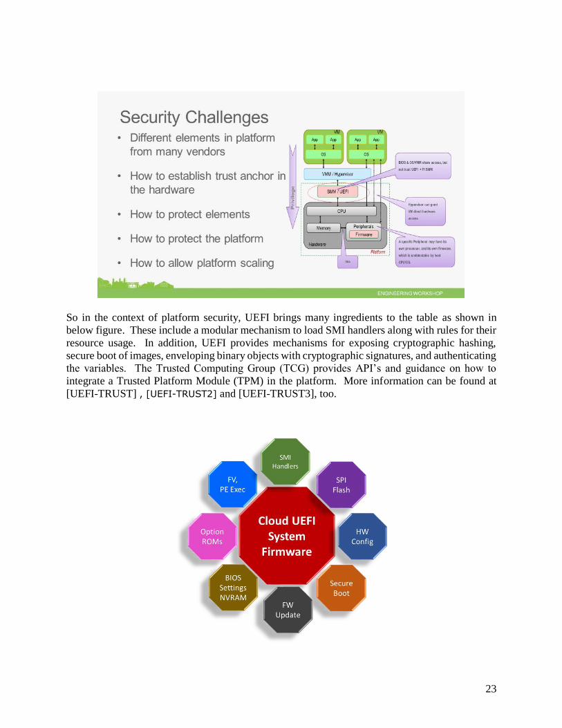
So in the context of platform security, UEFI brings many ingredients to the table as shown in
below figure. These include a modular mechanism to load SMI handlers along with rules for their
resource usage. In addition, UEFI provides mechanisms for exposing cryptographic hashing,
secure boot of images, enveloping binary objects with cryptographic signatures, and authenticating
the variables. The Trusted Computing Group (TCG) provides API’s and guidance on how to
integrate a Trusted Platform Module (TPM) in the platform. More information can be found at
[UEFI-TRUST] , [UEFI-TRUST2] and [UEFI-TRUST3], too.

24
And when discussing security, you need to have a threat model in mind, including the assets in the
platform and how they are to be protected. The presentation [UEFI-THREAT] describes a threat
model for UEFI based systems. UEFI Secure Boot, as described in the UEFI 2.4b specification,
is a critical capability in that it allows for protecting the underlying platform from possible pre-OS
malware. In addition, the existence of the feature and a record of its usage in the TPM can inform
the operating system or hypervisor that the machine was handed off in a trustworthy state. But as
noted earlier, the implementation of the firmware and its protection from unwanted updates is
imperative, and UEFI signed capsule updates and signed firmware images can help address that
concern, including adherence to [NIST]. The figure below shows these protections in practice in
a spatial, or layered view.
In addition to the spatial view shown above, a temporal view of platform security is in order. The
figure below shows the UEFI Platform Initialization (PI) based boot flow. The SEC, PEI, and
DXE are responsible for doing the basic platform initialization and germinating the UEFI services.
In fact, you can think of DXE as the “UEFI Core”. All of these PI elements should be under the
control of the platform supplier (PS) who will serve in the PS_Admin role. The Platform Owner
(PO), who typically administers the operating system or hypervisor, services as the PO_Admin.
For a vertically integrated supplier, the PS may be the same as the PO. After invoking BDS, the
machine will admit 3rd party code. At this point, typically signaled by the End of Dxe Event, the
DXE platform code should lock down the registers, flash parts, and any other elements that may
be perturbed by untrusted third party code. The code prior to the BDS can be thought of as OEM-

25
extensible, and the latter to the right is third-party extensible. UEFI on the right provides for the
rich interoperability between OEM, OSV, IHV, and ISV. To the left, the interoperability is
typically between the CPU, SI component, board manufacturer, and the OEM. The latter
extensibility should only be exposed in the factory or in the field view cryptographically signed
updates, as described in the earlier firmware update chapter of this paper.
The latest UEFI specifications build upon this protection technology by making it more
interoperable to have memory execution protection asserted. In addition, a new set of modes of
the UEFI Secure Boot state machine, namely Audit Mode and Deployed Mode, have been
introduced. This will allow for more options in provisioning UEFI Secure Boot from today’s more
rigid Setup Mode.
Finally, the above listed UEFI networking advances like “booting from a web server” can be
combined by the OsRecoveryOrder variable to allow for more stylized support of operating system
and OS loader recovery. Today recovery is ad hoc, with some vendors having a final boot option
as the ‘recovery agent,’ or an OEM-specific flow invoked upon failure of the main boot paths.
With the latest UEFI specification the recovery authorities and locations are explicitly exposed
and hardened relative to today’s boot options, which hearken back to 1998. Given the importance
of up-time and robustness in the Cloud, the ability to recover in a more robust, interoperable
fashion is another welcome addition of the UEFI2.5 into the Cloud deployments.
Summary This section gives brief introduction of security for UEFI. This spans from the UEFI extensible
environment down into the UEFI PI elements. Specific technologies and the intent of the
specification, when reduced to practice, is also described.

26
Tools and Diagnostics
Introduction
Verifying compliance of a compute node to the underlying specifications before deployment is
vital to commissioning of a datacenter. Also, any node / component failures during the operation
of a datacenter must be identified in a timely manner before they can be repaired and restored to
operation. Otherwise, there will be an impact to the overall capacity of the datacenter. Thus, one
must invest in tools and diagnostics to address these issues.
Constructing platform as per well-defined specifications holds key to a viable story for developing
tools and diagnostics (see below Figure).
c
Figure: UEFI Stack overview
The UEFI specification provides a well-defined interactive execution environment for running tools and diagnostics
by way of the UEFI Shell. The UEFI compliant BIOS can optionally include the UEFI shell. In addition, the shell
comes with built-in commands for accessing memory, driver management, device access, and PCI configuration
dump, file handling, etc. The UEFI also allows scripting, which can be used in automation.

27
Figure: UEFI Shell command environment
Some of the tools that we can employ for specific
• UEFI SCT
• PI SCT
• ACPI Compliance
• SMBIOS Compliance
In addition, for the purposes of risk assessment, the chipsec [CHIPSEC] tool can be employed. This tool can be
extended to meet specific platform concerns. The supported environments for this tool include Windows, Linux, and
UEFI over Python.

28
Figure: Chipsec tool architecture
The UEFI boot flow allows implementation of diagnostics OS (see Figure) as a last resort or terminal boot option.
One instance of such a diagnostics operating system could be the Linux UEFI Validation environment that can either
be hosted from service partition the local disk or over a network from a PXE service location.
Figure: Example flow for launching diagnostics OS in UEFI
The platform BIOS can also use auxiliary processors such as BMC to log error records to SEL or report status codes
using UEFI defined interfaces. This is one way a system can be diagnosed on a real-time basis. Optionally, the
platform BIOS can implement BIOS Firmware Volume based logging to capture runtime errors. Tools can be easily
developed to extract such errors to determine if a node needs to be serviced.

29
Conclusion
This paper has provided a brief overview the Cloud and the challenges that such scale-out
environments pose. And it is in the face of such challenges that UEFI based technology could be
brought to bear. These challenges and possible solutions include firmware update, diagnostics,
provisioning, and security.
30
Glossary
ACPI – Advanced Configuration and Power Interface. The specification defines a new interface
to the system board that enables the operating system to implement operating system-directed
power management and system configuration. For more information on ACPI specification, visit
http://acpi.info/
CHIPSEC: Platform Security Assessment Framework. The CHIPSEC is a framework for
analyzing security of PC platforms including hardware, system firmware including BIOS/UEFI
and the configuration of platform components. For more information on CHIPSEC, visit
https://github.com/chipsec/chipsec
HECI – Host Embedded Controller Interface. The HECI is a technology used in Active
Management Technology in Intel chipsets.
I2C - I2C is a serial protocol for two-wire interface to connect low-speed devices like
microcontrollers, EEPROMs, A/D and D/A converters, I/O interfaces and other similar peripherals
in embedded systems. For more information on I2C, visit http://i2c.info/
IPMI – Intelligent Platform Management Interface. The Intelligent Platform Management
Interface (IPMI) defines common platform instrumentation to enable interoperability, extensibility,
and scalability with intelligent hardware for enterprise-wide mission critical applications. For more
information on IPMI, visit http://www.intel.com/content/www/us/en/servers/ipmi/ipmi-
home.html
KCS – Keyboard Controller Style. The KCS is an interface used for communication between BMC
and payload coprocessor in IPMI architecture.
OCP – Open Compute Project. The Open Compute Project Foundation is a community of
engineers around the world whose mission is to design and enable the delivery of the most efficient
server, storage and data center hardware designs for scalable computing. For more information on
OCP, visit http://www.opencompute.org/
PCI – Peripheral Component Interconnect. The PCI bus is a local computer bus for attaching
hardware devices in a computer. For more information on PCI, visit https://www.pcisig.com/home
PI – Platform Initialization. Volume 1-5 of the UEFI PI specifications. For more information on
PI, visit http://www.uefi.org/specifications
SMBIOS – System Management BIOS. The System Management BIOS (SMBIOS) is the premier
standard for delivering management information via system firmware. Since its release in 1995,
the widely implemented SMBIOS standard has simplified the management of more than two
billion client and server systems. For more information on SMBIOS, visit
http://www.dmtf.org/standards/smbios

31
TPM – Trusted Platform Module. Trusted Platform Module (TPM) is an international standard for
a secure crypto-processor, which is a dedicated microprocessor designed to secure hardware by
integrating cryptographic keys into devices. For additional information on TPM, visit
http://www.trustedcomputinggroup.org/developers/trusted_platform_module
UEFI – Unified Extensible Firmware Interface. Firmware interface between the platform and the
operating system. Predominate interfaces are in the boot services (BS) or pre-OS. Few runtime
(RT) services. For more information on UEFI, visit http://uefi.org/

32
References
[ACPI] ACPI specification, Version 5.1 www.uefi.org
[ACPI6.0] http://www.uefi.org/sites/default/files/resources/ACPI_6.0.pdf
[CHIPSEC] Neri, Zimmer, “Open Source Test Tools for UEFI,” UEFI Plugfest, May 2014
http://www.uefi.org/sites/default/files/resources/2014_UEFI_Plugfest_04_Intel.pdf
https://www.youtube.com/watch?v=aV1DSF4cwGw
https://github.com/chipsec/chipsec
[CLOUD] “Above the Clouds: A Berkeley View of Cloud Computing”, Ambrust, et al, February
2009 http://www.eecs.berkeley.edu/Pubs/TechRpts/2009/EECS-2009-28.pdf
[CLUSTER] The Datacenter as a Computer: An Introduction to the Design of Warehouse-Scale
Machines, 20098
http://research.google.com/pubs/pub35290.html
[EDK2] UEFI Developer Kit www.tianocore.org
[IANA] Network boot architecture types http://www.iana.org/assignments/dhcpv6-
parameters/dhcpv6-parameters.xml
[IPXE] the IPXE project www.ipxe.org
[NIST] NIST 800-147, BIOS Protection Guidelines, April 2011
http://csrc.nist.gov/publications/nistpubs/800-147/NIST-SP800-147-April2011.pdf
[OCP] Open Compute Project, http://www.opencompute.org
[PI1.4] UEFI PI 1.4
specification http://www.uefi.org/sites/default/files/resources/PI_release_1_4.zip
[REDFISH] Redfish Specification http://www.redfishspecification.org/
[REST] Representational State Transfer
http://en.wikipedia.org/wiki/Representational_state_transfer
[SKYNET] the Skynet computer http://en.wikipedia.org/wiki/Skynet_%28Terminator%29
[UEFI] Unified Extensible Firmware Interface (UEFI) Specification, Version 2.4.b
www.uefi.org
[UEFI2.5] Unified Extensible Firmware Interface (UEFI) Specification, Revision
2.5 http://www.uefi.org/sites/default/files/resources/UEFI%202_5.pdf

33
[UEFI-BOOK] Zimmer, et al, “Beyond BIOS: Developing with the Unified Extensible
Firmware Interface,” 2nd edition, Intel Press, January 2011
[UEFI-CONFIG] Rothman, Zimmer, “Configuration from bare metal to the cloud - leveraging
modern systems to enhance manageability”, August 2014
https://firmware.intel.com/sites/default/files/resources/uefi-manageability-security-white-
paper.pdf
[UEFI-ITJ] Magnus Nystrom, Martin Nicholes, Vincent Zimmer, "UEFI Networking and Pre-OS
Security," in Intel Technology Journal - UEFI Today: Boostrapping the Continuum, Volume 15,
Issue 1, pp. 80-101, October 2011, ISBN 978-1-934053-43-0, ISSN 1535-864X
http://www.intel.com/content/www/us/en/research/intel-technology-journal/2011-volume-15-
issue-01-intel-technology-journal.html
[UEFI-NET] Zimmer, “A Quick History of UEFI Networking,” May 2013
https://www.researchgate.net/publication/258834396_A_Quick_History_of_UEFI_Networking
[UEFI-NETBOOT-BLOG] Zimmer, October 2013
http://vzimmer.blogspot.com/2013/10/configuring-ipv6-network-boot.html
[UEFI-OVERVIEW] Zimmer, Rothman, Hale, “UEFI: From Reset Vector to Operating
System,” Chapter 3 of Hardware-Dependent Software, Springer, February 2009
[UEFI-OCP] Filling UEFI/FW Gaps in the Cloud, Open Compute Summer conference, March
2015 http://www.uefi.org/sites/default/files/resources/OCP_SJC_2015_UEFI_for_Cloud.pdf
[UEFI-PRESS] http://www.uefi.org/node/897
[UEFI-SHELL] Michael Rothman, Tim Lewis, Vincent Zimmer, Robert Hale. Harnessing the
UEFI Shell: Moving the platform beyond DOS, ISBN-13: 978-1-934053-14-0. Intel Press,
January, 2011
[UEFI-THREAT] Robert Hale, Vincent Zimmer, “Threat modeling in modern system firmware,”
UEFI Summerfest, July 15-19, Redmond WA
http://www.uefi.org/sites/default/files/resources/Intel-UEFI-ThreatModel.pdf
[UEFI-TRUST] Zimmer, Shiva Dasari, Sean Brogan, “Trusted Platforms: UEFI, PI, and TCG-
based firmware,” Intel/IBM whitepaper, September
2009, http://www.cs.berkeley.edu/~kubitron/courses/cs194-24-S14/hand-
outs/SF09_EFIS001_UEFI_PI_TCG_White_Paper.pdf
[UEFI-TRUST2] Jacobs, Zimmer, "Open Platforms and the impacts of security technologies,
initiatives, and deployment practices," Intel/Cisco whitepaper, December 2012,
http://firmware.intel.com/sites/default/files/resources/Platform_Security_Review_Intel_Cisco_W
hite_Paper.pdf
https://firmware.intel.com/sites/default/files/resources/uefi-manageability-security-white-paper.pdf

34
[UEFI-TRUST3] Yao, Zimmer, “A Tour Beyond BIOS Implementing TPM2 Support in
EDKII”, September 2014
https://firmware.intel.com/sites/default/files/resources/A_Tour_Beyond_BIOS_Implementing_T
PM2_Support_in_EDKII.pdf
[UEFI-PI-SPEC] UEFI Platform Initialization (PI) Specifications, volumes 1-5, Version 1.3
www.uefi.org

35
Authors
Mallik Bulusu ([email protected]) is a UEFI lead in the Cloud Server
Infrastructure team at Microsoft Corporation.
Vincent Zimmer ([email protected]) is a Sr. Principal Engineer in
the Software & Services Group at Intel Corporation. Vincent chairs the UEFI
networking (UNST) and security subteams (USST), respectively.