White Paper Extending Digital Verification … Paper September 2014 Extending Digital Verification...
8
White Paper September 2014 Extending Digital Verification Techniques for Mixed-Signal SoCs with VCS ® AMS Author Helene Thibieroz Sr Staff Marketing Manager, Adiel Khan Sr Staff Engineer, Verification Group; Dave Cronauer Sr Corporate Applications Engineer, Analog/ Mixed-Signal Design Group, Synopsys, Inc. Introduction The growth in mixed-signal system-on-chip (SoC) designs is driven by many factors, including cost, performance and power consumption. This is fueled by many industry segments, including mobile communication, automotive, imaging, medical, networking and power management. The convergence of analog and digital blocks within the same die is driving the need for SoC design teams to adopt new verification techniques and methodologies to deal with this increased complexity. This white paper presents how the VCS AMS mixed-signal verification solution extends proven digital verification techniques to mixed-signal designs to deliver high-quality verification coverage of complex mixed- signal SoCs. To alleviate rising complexity and cost, SoC architectures are evolving and several trends can be observed: Increasing use of IP Analog IP usage is on the rise, driven by demands for higher accuracy sensing mechanisms, high-bit-rate data conversion, various interfacing protocols, pre-drivers/control loops, and accurate voltage/current references on-chip. Tighter integration between analog and digital As analog IP grows in complexity and contains more digital control logic, more interactions occur between the analog and digital portions of a design, leading to tighter integration. For example, digitally assisted analog architectures are commonly used when designing with advanced process nodes to alleviate transistor variability performance requirements, thus providing a better scaling and process control. Analog content Analog/Digital interaction Amount of verification Figure 1: Mobile and Internet of Things convergence drives SoC complexity
Transcript of White Paper Extending Digital Verification … Paper September 2014 Extending Digital Verification...

White Paper
September 2014
Extending Digital Verification Techniques for Mixed-Signal SoCs with VCS® AMS
Author
Helene Thibieroz
Sr Staff Marketing
Manager,
Adiel Khan
Sr Staff Engineer,
Verification Group;
Dave Cronauer
Sr Corporate
Applications
Engineer, Analog/
Mixed-Signal Design
Group, Synopsys, Inc.
IntroductionThe growth in mixed-signal system-on-chip (SoC) designs is driven by many factors, including cost, performance and power consumption. This is fueled by many industry segments, including mobile communication, automotive, imaging, medical, networking and power management. The convergence of analog and digital blocks within the same die is driving the need for SoC design teams to adopt new verification techniques and methodologies to deal with this increased complexity.
This white paper presents how the VCS AMS mixed-signal verification solution extends proven digital verification techniques to mixed-signal designs to deliver high-quality verification coverage of complex mixed-signal SoCs.
To alleviate rising complexity and cost, SoC architectures are evolving and several trends can be observed:
Increasing use of IP Analog IP usage is on the rise, driven by demands for higher accuracy sensing mechanisms, high-bit-rate data conversion, various interfacing protocols, pre-drivers/control loops, and accurate voltage/current references on-chip.
Tighter integration between analog and digitalAs analog IP grows in complexity and contains more digital control logic, more interactions occur between the analog and digital portions of a design, leading to tighter integration. For example, digitally assisted analog architectures are commonly used when designing with advanced process nodes to alleviate transistor variability performance requirements, thus providing a better scaling and process control.
Analog content
Analog/Digital interaction
Amount of verification
Figure 1: Mobile and Internet of Things convergence drives SoC complexity

2
An adjacent aspect of the tighter integration between analog and digital domains relates to power management on a chip. As analog IP needs to handle more power domains, power management is becoming more critical for today’s complex mixed-signal SoC designs. A recent customer survey by Synopsys indicated that more than 50 percent of designs have three or more voltage domains with multiple supply levels. With tighter integration of analog and digital and the need for analog IP to handle multiple power domains, SoC designers must extend their low-power verification methodologies to mixed-signal methodologies.
Growing need for testbench automation for mixed-signal designsThe need for high-reliability electronic systems has expanded beyond traditional automotive, military or aerospace applications. Today, this list includes communications infrastructure systems, medical intensive care and life support, consumer products, and so on. The need for exhaustive verification of mixed-signal SoCs means that verification teams need to extend digital testbench automation techniques to enable automated regression testing of mixed-signal SoCs. These techniques include: automated stimulus generation, coverage, and assertion-driven verification combined with low-power verification.
To meet these requirements, a mixed-signal verification solution must, at its foundation, offer high performance combined with broad language support and superior functional verification technologies. Synopsys’ VCS AMS solution, incorporating VCS functional verification and the CustomSim™ FastSPICE simulator, delivers advanced functional and low-power verification technologies combined with industry-best performance and capacity for fast mixed-signal SoC regression testing.
PerformanceVCS AMS benefits from a unique integration of high-performance FastSPICE and RTL simulation engines. This combination enables high-performance mixed-signal SoC functional verification with transistor-level accuracy. For additional performance, VCS AMS provides a multicore technology that can significantly reduce simulation runtimes while maintaining transistor-level accuracy, making it ideally suited for a regression test environment where throughput is critical.
Additionally, VCS AMS multicore technology provides significant run-time improvement for circuits with large analog content and high simulation activity.
VCS
VCS AMS
Functionalverification
FastSPICEsimulation
CustomSimNew!
New!
New!
• Performance
• Flexibility
Advanced modeling
AMS Testbench
Native Low Power
15 hours to 3 hoursRF RX, 300k tx
5X
Cores
Hours16
14
12
10
8
6
4
2
01 2 4 8 16 24
25 days to 7 daysPMU, 500k tx
3.5X
Cores
Days30
25
20
15
10
5
01 2 4 6 12
32 hours to <5 hoursDisplay, 400k tx
6.6X
Cores
Hours35
30
25
20
15
10
5
01 8
Figure 2: VCS AMS mixed-signal verification solution
Figure 3: VCS AMS multicore performance improvement for RF receiver, Power Management Unit and Display designs
3
FlexibilityA modern mixed-signal verification solution needs to support multiple design languages and topologies.
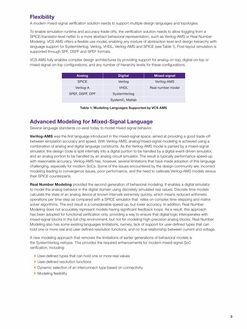
To enable simulation runtime and accuracy trade-offs, the verification solution needs to allow toggling from a SPICE/transistor-level netlist to a more abstract behavioral representation, such as Verilog-AMS or Real Number Modeling. VCS AMS offers a flexible use model, enabling any mixture of abstraction level and design hierarchy with language support for SystemVerilog, Verilog, VHDL, Verilog-AMS and SPICE (see Table 1). Post-layout simulation is supported through SPF, DSPF and SPEF formats.
VCS AMS fully enables complex design architectures by providing support for analog-on-top, digital-on-top or mixed-signal-on-top configurations, and any number of hierarchy levels for these configurations.
Advanced Modeling for Mixed-Signal LanguageSeveral language standards co-exist today to model mixed-signal behavior.
Verilog-AMS was the first language introduced in the mixed-signal space, aimed at providing a good trade-off between simulation accuracy and speed. With Verilog-AMS, analog/mixed-signal modeling is achieved using a combination of analog and digital language constructs. As the Verilog-AMS model is parsed by a mixed-signal simulator, the design code is split internally into a digital portion to be handled by a digital event-driven simulator, and an analog portion to be handled by an analog circuit simulator. The result is typically performance speed-up with reasonable accuracy. Verilog-AMS has, however, several limitations that have made adoption of this language challenging, especially for modern SoCs. Some of the issues encountered by the design community are: incorrect modeling leading to convergence issues, poor performance, and the need to calibrate Verilog-AMS models versus their SPICE counterparts.
Real Number Modeling provided the second generation of behavioral modeling. It enables a digital simulator to model the analog behavior in the digital domain using discretely simulated real values. Discrete time models calculate the state of an analog device at known intervals extremely quickly, which means reduced arithmetic operations per time-step as compared with a SPICE simulator that relies on complex time-stepping and matrix solver algorithms. The end result is a considerable speed-up, but lower accuracy. In addition, Real Number Modeling does not accurately represent models having significant feedback loops. As a result, this approach has been adopted for functional verification only, providing a way to ensure that digital logic interoperates with mixed-signal blocks in the full-chip environment, but not for modeling high-precision analog blocks. Real Number Modeling also has some existing languages limitations, namely, lack of support for user-defined types that can hold one or more real and user-defined resolution functions, and no true relationship between current and voltage.
A new modeling approach that removes the limitations of earlier generations of behavioral models is the SystemVerilog nettype. This provides the required enhancements for modern mixed-signal SoC verification, including:
`` User-defined types that can hold one or more real values
`` User-defined resolution functions
`` Dynamic selection of an interconnect type based on connectivity
`` Modeling flexibility
Analog Digital Mixed-signal
SPICE Verilog Verilog-AMS
Verilog-A VHDL Real number model
SPEF, DSPF, DPF SystemVerilog
SystemC, Matlab
Table 1: Modeling Languages Supported by VCS AMS

4
Because of its performance and modeling capabilities, SystemVerilog nettype is well-suited for fast and accurate mixed-signal SoC functional verification. VCS AMS supports multiple behavioral modeling types including Verilog-AMS, Real Number Modeling and the new SystemVerilog nettype.
A simple example in Figure 5 shows SystemVerilog nettype for multiple drivers. In the top module, driver and receiver module ports are declared as nettype. The top-level model connects those ports together with an interconnect (respectively, dr3, dr4 and iws). As shown by the waveform window, the interconnect iws resolved value is the summation of dr3 and dr4.
SystemVerilog-based AMS TestbenchAs the need to include more embedded analog IP increases, the verification environment needs to accommodate both digital and mixed-signal verification. The SystemVerilog-based AMS Testbench technology expands on the industry standard Universal Verification Methodology (UVM) to provide a solution that extends proven digital testbench techniques to mixed-signal designs. This technology complements a traditional digital verification environment with additional components that can drive analog IP, such as ADCs or clock generators.
Verilog-AMS• Behavioral modeling with mixed constructs• Need calibration and modeling expertise
Real NumberModel
• Faster approach• Loss in accuracy• Modeling limitations for Analog
SystemVerilogNettype
• Extend Real Number model for Analog• Faster than Verilog- AMS
Multiple driver configuration:Results simulations show
interconnect iws as a resolved valueof dr3 and dr4
Figure 4: Verilog-AMS and Real Number Modeling leading to SystemVerilog nettype
Figure 5: Example showing multiple drivers using SystemVerilog nettype

5
To ensure a high level of quality, performance and confidence, AMS Testbench technology leverages best-in-class verification practices, including:
`` Predefined automated stimulus generators
`` Assertion-based checking logic
`` Observation points defined by functional coverage and verification planning.
By fully supporting AMS Testbench, VCS AMS delivers a comprehensive solution for coverage-driven verification and planning that simultaneously encompasses digital and mixed-signal needs.
Mixed-signal stimulus pattern generation in VCS AMSTo be able to drive and control analog traffic, AMS Testbench provides predefined pattern generators that can be interchanged to produce a variety of electrical signal waveforms. Basic capabilities include sine, sawtooth and square waveform sources, while more advanced features enable more complex scenarios (see Table 2).
Additionally, source generators can be combined to inject more complex traffic. A very interesting application is noise modeling. For example, white noise can be created by superimposing a small voltage fluctuation on a voltage carrier. Sequencing source generators can also be performed (for example, a sine source followed by a sawtooth source).
In addition to predefined voltage shapes, it is also possible to write custom voltage source generators that provide flexibility to implement any type of equation. For example, a low-pass filter can be easily modeled and controlled through SystemVerilog.
Because of the versatility of source generators, it becomes possible to provide digital verification mechanisms for analog, as analog fluctuations are being controlled by SystemVerilog.
AMS assertions in VCS AMSFor verification to be effective, the analog nodes must be monitored and checked for correctness. AMS Testbench includes predefined assertions and checkers that can be applied to analog nodes and, therefore, verify digital and analog domain interactions. Using this technology, the designer can first leverage the concept of SystemVerilog assertions and extend it to analog nodes within a mixed-signal design. Immediate, concurrent assertions or sequences of assertions are supported. An immediate assertion is shown in Figure 6, where the top.analog_node is being checked to remain below 1.8V on each rising cycle.
basic capabilities Advanced capabilities
Sine waveform Injection of random voltage
Square waveform Multi-generation modulation
Sawtooth waveform Custom Voltage
Table 2: AMS Testbench Source Generator Capabilities
clk
VDD=1.8V
top.vref.analog _ node
“Node is greater than VDD”
Synchronousimmediate assertion
of analog node
always @ (posedege clk) assert(top.vref.analog _ node <= 1.8) else $error(”Node is greater than VDD”);
Figure 6: SystemVerilog immediate assertion on an analog node

6
In addition, to be able to control assertions with a digital clock, analog events can also be used as the assertion triggering event.
A complementary approach to verify analog signals is to define some common analog checkers. AMS Testbench provides four main checkers, as highlighted in Table 3.
These checkers can also be modeled as an additional level of abstraction as UVM components and can therefore be controlled in a UVM environment.
Mixed-signal coverage-driven verification and planning in VCS AMSDigital verification relies on the concept of coverage: observations of all potential behaviors must be captured using a reporting technology. By enabling observation of a full range of behaviors on analog nodes and structural coverage, AMS Testbench empowers designers to include analog metrics in their coverage and, therefore, use the same coverage and verification model for their mixed-signal SoCs.
As a natural progression, analog and digital coverage can now be aggregated in the same verification plan. By clearly referencing both analog and digital coverage groups, both domains can be verified together as shown by Figure 7. In this example, the cp_vi and cp_vmax terms refer to digital outputs and analog inputs while the cc term refers to the cross-coverage of analog inputs and digital outputs. While the cp_vi term highlights a fairly high coverage (93.75%), the cp_vmax term indicates a poor result for the analog inputs (33.3%) requiring a more extensive coverage from the analog side.
Table 3: AMS checkers for Threshold, Stability, Slew Rate and Frequency
Checkers
sv_ams_threshold_checker
Checks that analog signal remains within a fiven high and low threshold. Can perform this check synchronously or asynchronously.
sv_ams_stability_checker
Checks the analog signal remains below or above a given threshold.Can perform this check synchronously or asynchronously.
sv_ams_slew_checker
Checks that anaolog signal rises/falls with a given slew rate (+/- tolerance).Can perform this check synchronously or asynchronously.
sv_ams_frequency_checkerChecks that analog signal frequency is within a given tolerance.
Figure 7: Coverage report for analog and digital

7
Low-Power VerificationAccurate and efficient low-power and multiple power domain verification require both knowledge of the overall system’s power intent and careful tracking of signals crossing these power domains. VCS AMS offers an easy-to-use, automated verification solution for low-power and multiple-power domain designs. By leveraging VCS’ Native Low Power (NLP) technology, VCS AMS provides a unique capability to accurately pass power intent from the analog domain to the digital domain. NLP maintains VCS’ ease of-use for low-power design by enabling VCS to directly read UPF low-power design intent. By enabling UPF to control and monitor the power state for SPICE, this technology is extended for mixed-signal designs.
An example is shown in Figure 8 for a design with two power domains. First, the design’s power intent is modeled in UPF by adding power levels, level-shifter and isolation cells. This power intent is then accurately simulated by NLP technology.
Assuming a need for more accuracy, the “High Speed” domain block is substituted by its SPICE-level model counterpart. Using NLP technology, input and output analog signals are automatically converted to proper UPF levels, ensuring correctness of the power intent.
Key benefits of VCS AMS low power verification technology are:
`` UPF fully controls the power state for SPICE, making it compatible with a coverage-driven verification methodology
`` The UPF flow is fully preserved by supporting the same model used by VCS NLP. Existing design and UPF files are preserved and few mixed-signal commands are required.
From a technical specification standpoint, the translation of the power intent from digital to analog includes several components (see Figure 9):
`` Automatic power supply adjustment: UPF levels are converted to analog voltage sources using UPF functions and real to electrical, r2e, interface element. As the testbench changes, UPF functions supply_on() and supply_off() define the behavior of the supplies, allowing the related analog supply to track this value. Simultaneously, the UPF level is converted to an accurate voltage value for the analog block by automatically inserting a r2e element.
`` Accurate input and output signals: interface elements d2a and a2d are automatically placed on the analog/digital boundary to ensure voltage levels are being correctly evaluated and passed. Digital inputs get their logic values from VCS and are converted to analog signals while analog output signals are compared to the supply value and converted to logic signals for VCS. If more flexibility is required, additional mixed-signal d2a simulation commands can be used to further customize the mixed-signal interface.
top
Vtyp
“High Speed”domain(SPICE)
R2E
A2D
D2A ISOLS LS
“High Speed”domain
Vtyp“Low Power”
domain
VREG POR
I/Opads
Vlow
Vtyp
Vtyp
“Always On” domain
Vlow
LS
LS
LS
LS LS
LS
IO nets
IO nets
ISO
ISO
Figure 8: Accurate verification of a mixed-signal design using VCS AMS low-power technology

09/14.RP.CS4809.
Synopsys, Inc. • 700 East Middlefield Road • Mountain View, CA 94043 • www.synopsys.com
©2014 Synopsys, Inc. All rights reserved. Synopsys is a trademark of Synopsys, Inc. in the United States and other countries. A list of Synopsys trademarks is available at http://www.synopsys.com/copyright.html . All other names mentioned herein are trademarks or registered trademarks of their respective owners.
Electrical Rule Checks for Low-/Multiple-Power Domain DesignsCustomSim Circuit Check (CCK) technology provides a comprehensive set of static and dynamic circuit checks to quickly identify electric rule violations and power management design errors. With this technology, mixed-signal designers can identify violations such as missing level-shifters, leakage paths or power-up checks at the SoC level (see Figure 10) and avoid significant design errors before tapeout.
ConclusionWith industry-best mixed-signal verification performance and capacity, a proven SystemVerilog-based verification methodology extended for mixed signal designs, and advanced functional and low-power verification technologies, VCS AMS provides a faster solution for mixed-signal SoC verification and a superior environment to rapidly deploy a coverage-driven methodology for mixed-signal regression.
VtypTestbench
“High Speed”domain(SPICE)
R2E
A2D
D2A ISOLS LS
Stacking MOSFET between rails
Leakage path induced by gated power
Missing level shifter check
Figure 9: UPF power intent translation from digital to analog
Figure 10: Low-power checks supported by CCK