White paper - EXCELIA HIFI · ATF is a resampling process that allows audio data to be interpolated...
15
White paper © Cambridge Audio 2006 Version 1.0 November 2006 Azur 840C Up-sampling CD player Matthew Bramble, Cambridge Audio Thierry Heeb, Anagram Technologies Tim Llewellynn, Anagram Technologies The 840C up-sampling CD player is part of Cambridge Audio’s flagship '8' series range, designed to match our 840A Class XD™ integrated amplifier itself the subject of a white paper and patent- pending amplifier technology. Background When we considered a matching CD player we examined the necessary factors that make a truly great CD player – imaging, timing and overall sound quality. By dissecting each in turn we came up with a technological shopping list for the 840C. Incredibly high quality DACs would of course be required. For best stereo imaging properties it was decided that two would be used, one for the left channel and one for the right, this would allow for discrete circuits for the very best channel separation. In addition the circuits could then be made symmetrical, giving them identical properties, further improving imaging. If two DACs were used we could exploit the benefit of dual differential mode, reducing distortion and allowing a true balanced output. DC servos could be used allowing no capacitors at all in the signal path. Lastly if we could use a DSP to process the data we could perform our own digital filtering, jitter suppression and even up-sampling to a higher sample rate, ideally combining this with a superior output filter using a Bessel topology with constant group delay and linear phase, the best kind of filter to use with excellent timing characteristics. The completed wish list was: • Upsampling and jitter suppression via DSP • Twin dual differential 24-bit DACs • DC coupled outputs with DC servos • Fully balanced filter topology
Transcript of White paper - EXCELIA HIFI · ATF is a resampling process that allows audio data to be interpolated...

White paper
© Cambridge Audio 2006 Version 1.0
November 2006
Azur 840C Up-sampling CD player Matthew Bramble, Cambridge Audio
Thierry Heeb, Anagram Technologies
Tim Llewellynn, Anagram Technologies
The 840C up-sampling CD player is part of Cambridge Audio’s flagship '8' series range, designed to
match our 840A Class XD™ integrated amplifier itself the subject of a white paper and patent-
pending amplifier technology.
Background
When we considered a matching CD player we examined the necessary factors that make a truly
great CD player – imaging, timing and overall sound quality. By dissecting each in turn we came up
with a technological shopping list for the 840C.
Incredibly high quality DACs would of course be required. For best stereo imaging properties it was
decided that two would be used, one for the left channel and one for the right, this would allow for
discrete circuits for the very best channel separation. In addition the circuits could then be made
symmetrical, giving them identical properties, further improving imaging. If two DACs were used we
could exploit the benefit of dual differential mode, reducing distortion and allowing a true balanced
output. DC servos could be used allowing no capacitors at all in the signal path. Lastly if we could
use a DSP to process the data we could perform our own digital filtering, jitter suppression and
even up-sampling to a higher sample rate, ideally combining this with a superior output filter using a
Bessel topology with constant group delay and linear phase, the best kind of filter to use with
excellent timing characteristics.
The completed wish list was:
• Upsampling and jitter suppression via DSP
• Twin dual differential 24-bit DACs
• DC coupled outputs with DC servos
• Fully balanced filter topology
White paper
© Cambridge Audio 2006 Version 1.0
• Linear phase Bessel filters for constant group delay
In order to achieve the above we needed to find an upsampling technology which would meet our
needs. As luck would have it around this time we met Anagram Technologies of Switzerland who
had long been offering upsampling algorithm and modules for some very high end manufacturers.
Anagram was keen to work with us and agreed to even customise and license their code to us for
inclusion in our own DSP. After careful consideration and critical evaluation of all options, we
decided on a BF352 32 Bit ‘Black Fin’ DSP from Analog Devices, running a custom version of their
patented ATF™ (Adaptive Time Filtering) upsampling process known by Anagram as Q5™
Upsampling.
Q5™ Upsampling with ATF™
Key to the success of the 840C is a technology called ATF. ATF is a resampling process that allows
audio data to be interpolated at a higher precision than standard techniques used in off-the-shelf
sample rate converters. ATF uses an advanced polynomial curve fitting algorithm that closer
matches the original audio data, than sample-and-hold, or piece-wise linear estimation
interpolators, commonly used today. This advanced technique allows jitter invoked errors in the
resampling process to be minimized to a point where they no longer become relevant, and as this
process is extremely efficient, ATF allows Q5 Upsampling to be implemented on a relatively low cost
DSP. Critically this has enabled Cambridge Audio to bring this high-end technology to a new mid-
range price level.
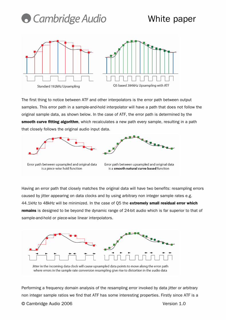
Standard interpolators are of two types, sample-and-hold, or piece-wise linear and typically have a
maximum output signal sampling frequency limited to 192kHz. The diagram below shows a
comparison between normal upsampling and Q5 Upsampling running at 384kHz using ATF in the
theoretical case where all clocking is jitter free. In the following diagrams we will show how ATF
provides superior performance in the presence of jitter and how it minimizes the impact of
resampling jitter.
White paper
© Cambridge Audio 2006 Version 1.0
The first thing to notice between ATF and other interpolators is the error path between output
samples. This error path in a sample-and-hold interpolator will have a path that does not follow the
original sample data, as shown below. In the case of ATF, the error path is determined by the
smooth curve fitting algorithm, which recalculates a new path every sample, resulting in a path
that closely follows the original audio input data.
Having an error path that closely matches the original data will have two benefits: resampling errors
caused by jitter appearing on data clocks and by using arbitrary non integer sample rates e.g.
44.1kHz to 48kHz will be minimized. In the case of Q5 the extremely small residual error which
remains is designed to be beyond the dynamic range of 24-bit audio which is far superior to that of
sample-and-hold or piece-wise linear interpolators.
Performing a frequency domain analysis of the resampling error invoked by data jitter or arbitrary
non integer sample ratios we find that ATF has some interesting properties. Firstly since ATF is a

White paper
© Cambridge Audio 2006 Version 1.0
non-linear process, resampling errors are uncorrelated with amplitude, which is not the case with
the sample and hold interpolator, and secondly due to the smooth time domain function of ATF,
error harmonics will be greatly reduced.
What is jitter?
The basis of digital audio theory is Shannon’s sampling theorem. It states that a signal may be
completely recovered by its samples, provided the sampling rate is at least twice the highest
frequency present in the signal. One key assumption of Shannon’s sampling theorem is that the
sampling is uniform, i.e. the sampling rate is constant (fixed sampling period Ts(n) = Ts) as shown
in Figure 1.
Figure 1: Uniform sampling according to Shannon’s theorem.
Jitter is defined as the deviation from uniform sampling or, in other words, as the time fluctuations
of the sampling period. The general model for a jittered sampling signal is given by:
Ts(n) = Ts + e(n) where e(n) is a zero-mean random process.

White paper
© Cambridge Audio 2006 Version 1.0
This introduces time domain distortion as the sampling instants are moved from their intended
position. Jitter based distortion is particularly harmful for audio quality as the human ear is
especially sensitive to timing errors. Indeed the human ear relies on time domain information to
locate events in space-time. Jitter therefore blurs the timing information of the reproduced audio
signal, resulting in surprisingly degraded audio quality.
Jitter also introduces amplitude modulation products into modern DACs particularly bitstream types
which rely on the intrinsic timing of the individual data packets to determine each conversion of the
bitstream, these DACs whilst they can provide an excellent musical performance need very careful
control of their time domain behaviour.
Assuming already very good Total Harmonic Distortion performance (as is now the norm with most
well designed audiophile CD players) jitter is arguably now the most detrimental form of distortion in
digital audio playback and recording systems.
Figure 2 shows the same signal portion as above except with exaggerated jitter to illustrate clearly
the resulting distortion.
Figure 2: Non-uniform sampling resulting from jitter.
Where does jitter appear?
As no perfect components exist, jitter is in fact present in any digital circuit. It already originates in
the system’s oscillator where non-perfect switching electronics contribute to it. Jitter is also created
by circuit traces acting like antennas picking up noise from all kind of noise sources in the design
or generated by component imperfections or thermal noise. Jitter is also introduced where
imperfect power supplies allow the switching thresholds of digital ICs to be modulated. Reflections

White paper
© Cambridge Audio 2006 Version 1.0
in imperfectly terminated high frequency traces or signal wires cause ringing which also introduces
jitter. Finally jitter can be introduced by the data itself. Capacitance in traces and other effects allow
the switching threshold of the ICs to be modulated by the very data itself, a phenomenon known as
data related jitter.
Therefore jitter is a natural element of every real world digital circuit design. The trick as ever is to
minimise it at source and crucially to remove it at the conversion point from the digital to analog
domain as will be seen later.
How do we reduce jitter?
Firstly a good understanding of the causes of jitter as above allows a lot of jitter sources to be
minimised at source. The 840C in common with other Cambridge Audio CD players uses a high
precision master clock, careful control of high frequency signal lines for impedance, cross-talk and
a raft of other careful design considerations.
But with these all in place there is an inevitable small amount of jitter left that we wanted to
eliminate for the very best performance possible. The ‘traditional’ way to do this in a high end CD
player is with a Phase Locked Loop (PLL) or Sample Rate Converter (SRC).
PLLs are often used to “de-jitter” a signal by driving a Voltage Controlled Crystal Oscillator (VCXO) to
be synchronous to a given clock source.
For a PLL solution a high accuracy VCXO master clock is used to clock the audio data into the DAC.
This clock is then locked to the average rate of the incoming data which is also buffered. The idea
is to split the timing of the outgoing data from that going in so that the jitter in the outgoing data is
determined purely by the new accurate master clock.
However to avoid loss of samples when the two clocks are asynchronous the data is buffered
(usually in RAM) and the master clock made variable so that its average rate matches the incoming
rate. To do this PLLs rely on comparator and loop filter to compare the timing of high accuracy
master clock with the incoming clocks.
White paper
© Cambridge Audio 2006 Version 1.0
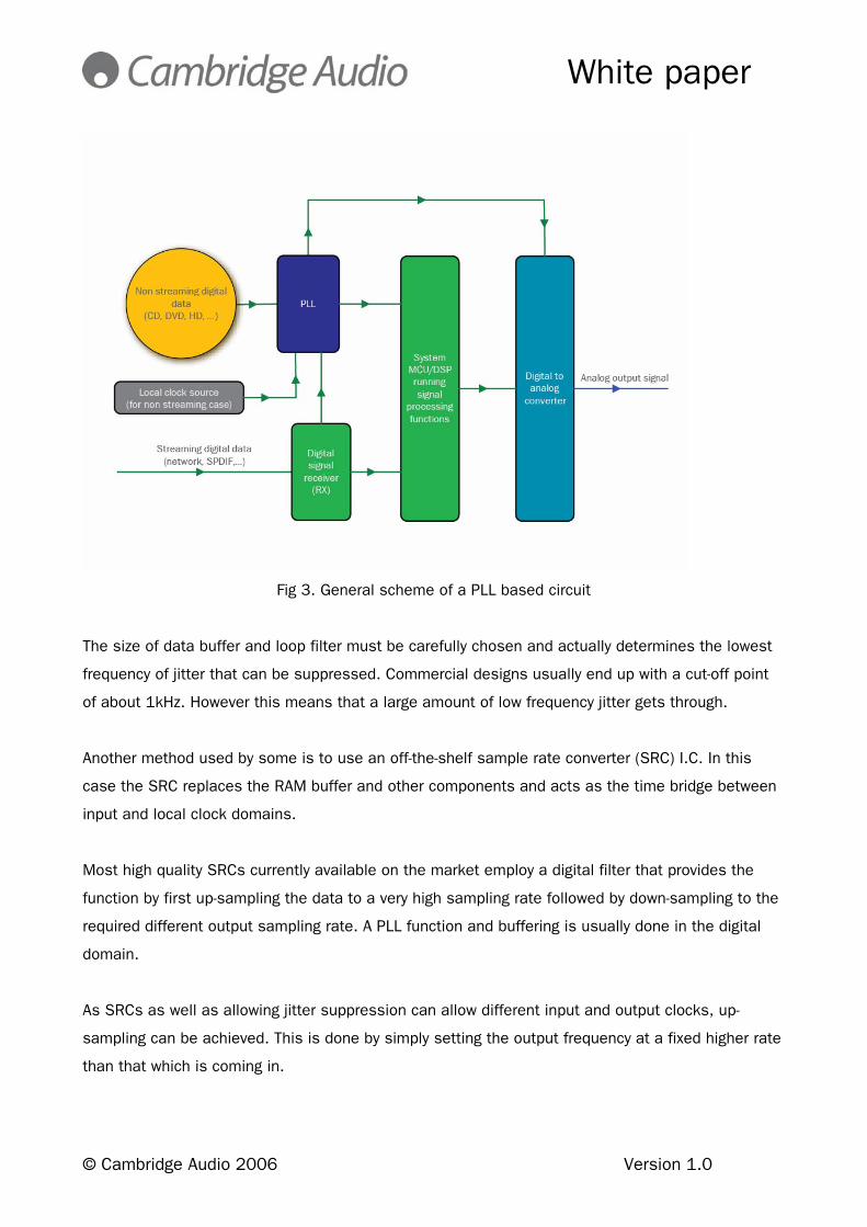
Fig 3. General scheme of a PLL based circuit
The size of data buffer and loop filter must be carefully chosen and actually determines the lowest
frequency of jitter that can be suppressed. Commercial designs usually end up with a cut-off point
of about 1kHz. However this means that a large amount of low frequency jitter gets through.
Another method used by some is to use an off-the-shelf sample rate converter (SRC) I.C. In this
case the SRC replaces the RAM buffer and other components and acts as the time bridge between
input and local clock domains.
Most high quality SRCs currently available on the market employ a digital filter that provides the
function by first up-sampling the data to a very high sampling rate followed by down-sampling to the
required different output sampling rate. A PLL function and buffering is usually done in the digital
domain.
As SRCs as well as allowing jitter suppression can allow different input and output clocks, up-
sampling can be achieved. This is done by simply setting the output frequency at a fixed higher rate
than that which is coming in.

White paper
© Cambridge Audio 2006 Version 1.0
Fig 4. of a SRC
However using an SRC whilst it would indeed have provided a measure of jitter suppression and
allowed us to interpolate the incoming data to 24-bit and 192kHz isn’t the best that can be done.
For one, we would have been restricted to 192kHz. SRC chips are typically aimed at pro-audio
implementations where the data is transmitted/received over S/PDIF. The maximum sample
frequency SPDIF supports is 192kHz.
In order to allow the use of a low order filter topology, the higher the sample frequency the better.
Using our own DSP based solution would allow higher sample rates to be achieved, 384kHz in the
case of the 840C. Also the sophisticated curved fitting and other technologies uses in the ATF
process provide real benefits in terms of both sonic and measured qualities as will be seen later.
Where does jitter matter?
Jitter actually only matters at the digital to analogue (or analogue to digital) conversion stage. As
long as a signal remains in the digital domain and satisfies all electrical timing specifications, jitter
is of no concern. If it did, it would be impossible to listen to any music stored on a computer’s hard-
drive as data transmission to the main processor and then to the audio section is packet based

White paper
© Cambridge Audio 2006 Version 1.0
without any reference to a real clock source. Only at playback when audio is streamed through the
D/A converter does timing information, and hence jitter, matter.
Digital to analogue conversion is often considered (or defined) as the conversion from discrete
domain data into continuous domain data. However we think this definition lacks one important
point which is time. Thus an extended definition of digital to analog conversion could be the
conversion of data from a discrete domain into continuous domain data and the conversion from
abstract time to real-world time. Indeed when stored as pure digital information (such as on a
CD/DVD or on a hard-drive) the audio data file only carries symbolic information about the content’s
sampling rate; while in this form, it has no relation with a real-time base.
Jitter at the digital to analogue domain boundary
The task of a digital to analogue (or analogue to digital) converter is twofold: conversion of discrete
symbolic data (binary code) to continuous real data (electrical current or voltage) and the
conversion of abstract-time to real-world time, basically some kind of synchronisation.
Incorporated in Anagram’s patented Q5 Upsampling is a form of synchronisation called DSS™ (Data
to System Synchronisation). Instead of adapting the system’s operating frequency to the incoming
time base or to use a RAM buffer or an SRC chip, DSS™ uses a software based upsampler (sample
rate converter) based on their Q5™ SRC kernel to perform abstract to real-world time conversion
using a local high quality single clock.
The fact that all clocks in the system are made synchronous to this local high quality clock is one of
the key aspects of DSS™. As such the DSP and all other clocked devices in the system are driven
using a clock derived synchronously from this local clock source. The general idea behind DSS™ is
to use a single time base and to adapt the audio data to this time base result in the extraordinary
jitter rejection performance seen in the implementation of this technology. Furthermore, the
complete system being synchronous, possible noise appearing in the output stage and resulting
from multiple clocks interaction is reduced to a minimum.

White paper
© Cambridge Audio 2006 Version 1.0
Figure 8 shows the structure of a DSS™ synchronisation based digital audio playback unit.
See below for a real world comparison of the output of the 840C’s up-sampling DSP and a well
know competing SRC.
So we have seen that the 840C’s up-sampling technology can give a very smooth high resolution
up-sampled digital audio waveform with low distortion which can be used to eke the very best
performance from modern 24-bit DACs. The idea being to use the artificially higher resolution data
created to get as close as possible to the true 16-bit performance of the CD disc, in our case we
chose to use two AD1955 24-bit DACs from Analog Devices. These are very high end products

White paper
© Cambridge Audio 2006 Version 1.0
giving excellent performance with the advantage of true balanced outputs. Finally the process also
had another big advantage for us in that the high sampling frequency could allow us to use a
special filter topology for the output stage with many advantages.
The 840C’s anti-aliasing / reconstruction filter
The 840C uses a Linear Phase Bessel output filter, arguably the best possible type of filter for
audio use. However these filters are rarely seen in audio equipment as the filter response has quite
slow roll off in the frequency domain.
The term Bessel refers to a type of filter response, not a type of filter. It features flat group delay in
the passband:
This is the characteristic of Bessel filters that makes them valuable to designers. Very few filters
are designed with high slew rates or square waves in mind. Most of the time, the signals filtered
are sine waves, or close enough that the effect of harmonics can be ignored. If a waveform with
high harmonic content is filtered, such as a square wave, the harmonics can be delayed with
respect to the fundamental frequency if a Butterworth or Chebyshev response is used. The Fourier
Series of a square wave is:
This means that a square wave is an infinite series of odd harmonics, or sine waves, summed
together to create the square shape. Obviously, if a square wave is to be transmitted without
distortion, all of the harmonics - out to infinity - must be transmitted. This means that the square
wave can be high pass filtered without distortion, if the 3 dB point of the filter is significantly lower

White paper
© Cambridge Audio 2006 Version 1.0
than the fundamental. If the square wave is low pass filtered, however, the situation changes
dramatically. Harmonics will be eliminated, producing distortion in the square wave. It is the job of
the designer to decide just how many harmonics must be passed and what can be eliminated.
Suppose that the designer wants to keep five harmonics. The resulting waveform looks something
like this:
This may be acceptable to the designer - it depends on the timing of the leading and trailing edge of
the waveform. The elimination of harmonics will result in rounding of the edges, and therefore delay
in the leading and trailing edges of the digital signal. Of more importance, the harmonics that are
passed will not be delayed.
The Bessel approximation also has a very smooth passband and stopband response, like the
Butterworth. However for the same filter order, the stopband attenuation of the Bessel
approximation is much lower that that of the Butterworth approximation. See below:
This is the issue that often precludes its use. Aliasing noise inherent in sampled digital audio will
be less attenuated by a Bessel filter than other types. However if the aliasing can be moved up in
frequency to be well out of the audio range and within the range where the Bessel filter does apply
good attenuation this problem can be solved.

White paper
© Cambridge Audio 2006 Version 1.0
The 840C by applying 384kHz up-sampling does exactly this.
It should also be noted that there is no ripple in the passband of a Bessel filter.
The phase response of the three filter types is now shown below. The Bessel response also has
the slowest rate of change of phase.
So the Bessel topology has been shown to have minimum ripple in the pass band, slowest rate of
change of phase and constant group delay in the pass band. All these features make it perfect for
audio use if its relatively slow roll off can be accommodated, in the 840C we were able to do this
happily by up-sampling all audio to 384kHz in DSP.
Other features
Two digital inputs are fitted allowing other digital sources to be connected directly to the 840C and
up-sampled, the 840C then operates as a very high quality DAC.
A digital output is also fitted which can even output upsampled data at various rates and word
widths, independent from the main audio output, which is always set at 24/384 for best sound
quality.
In addition to these audiophile features, Control Bus Input/Output, IR Emitter Input and RS232
control are provided to make it easy to integrate the 840C into custom installation systems if
desired.
White paper
© Cambridge Audio 2006 Version 1.0
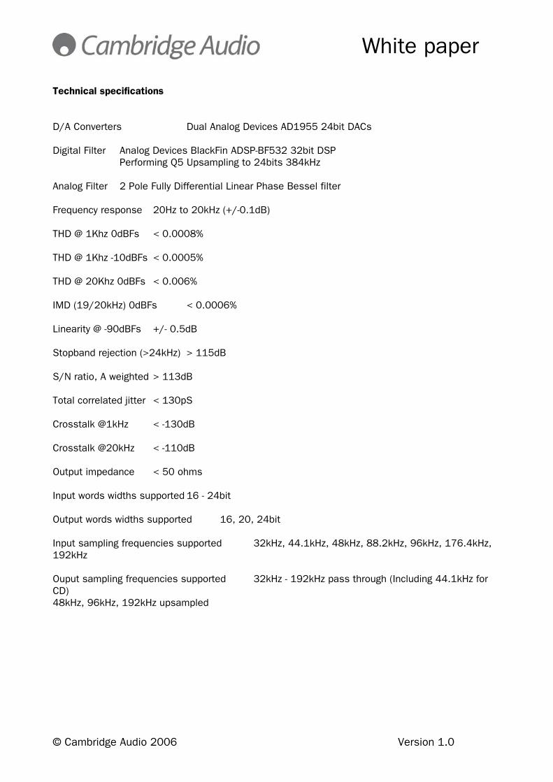
Technical specifications D/A Converters Dual Analog Devices AD1955 24bit DACs Digital Filter Analog Devices BlackFin ADSP-BF532 32bit DSP Performing Q5 Upsampling to 24bits 384kHz Analog Filter 2 Pole Fully Differential Linear Phase Bessel filter Frequency response 20Hz to 20kHz (+/-0.1dB) THD @ 1Khz 0dBFs < 0.0008% THD @ 1Khz -10dBFs < 0.0005% THD @ 20Khz 0dBFs < 0.006% IMD (19/20kHz) 0dBFs < 0.0006% Linearity @ -90dBFs +/- 0.5dB Stopband rejection (>24kHz) > 115dB S/N ratio, A weighted > 113dB Total correlated jitter < 130pS Crosstalk @1kHz < -130dB Crosstalk @20kHz < -110dB Output impedance < 50 ohms Input words widths supported 16 - 24bit Output words widths supported 16, 20, 24bit Input sampling frequencies supported 32kHz, 44.1kHz, 48kHz, 88.2kHz, 96kHz, 176.4kHz, 192kHz Ouput sampling frequencies supported 32kHz - 192kHz pass through (Including 44.1kHz for CD) 48kHz, 96kHz, 192kHz upsampled

White paper
© Cambridge Audio 2006 Version 1.0
Notices
• Q5™ Upsampling & ATF™ Adaptive Time Filtering are trademarks of Anagram Technologies SA
• ‘Black Fin’ DSP is a trademark of Analog Devices
• Reproduction in whole or in part can be authorized by prior written agreement