Whirlpool Routing for Mobility - Stanford University
10
Whirlpool Routing for Mobility Jung Woo Lee Stanford University Stanford, CA USA [email protected] Branislav Kusy CSIRO ICT Centre Brisbane, Australia [email protected] Tahir Azim Stanford University Stanford, CA USA [email protected] Basem Shihada KAUST Thuwal, Saudi Arabia [email protected] Philip Levis Stanford University Stanford, CA USA [email protected] ABSTRACT We present the Whirlpool Routing Protocol (WARP), which effi- ciently routes data to a node moving within a static mesh. The key insight in WARP’s design is that data traffic can use an existing routing gradient to efficiently probe the topology, repair the routing gradient, and communicate these repairs to nearby nodes. Using simulation, controlled testbeds, and real mobility experi- ments, we find that using the data plane for topology maintenance is highly effective due to the incremental nature of mobility up- dates. WARP leverages the fact that converging flows at a desti- nation make the destination have the region of highest traffic. We provide a theoretical basis for WARP’s behavior, defining an “up- date area” in which the topology must adjust when a destination moves. As long as packets arrive at a destination before it moves outside of the update area, WARP can repair the topology using the data plane. Compared to existing protocols, such as DYMO and HYPER, WARP’s packet drop rate is up to 90% lower while sending up to 90% fewer packets. Categories and Subject Descriptors C.2.2 [Computer-Communication Networks]: Network Proto- cols General Terms Algorithms, Design, Experimentation, Performance Keywords Mobile Routing, Sensor Network, Collection Protocol 1. INTRODUCTION Unlike their wired brethren, wireless nodes can move freely and untethered. This flexibility introduces significant complications to networking. While the past decade of research on mobile routing has generated a large number of elegant and intellectually interest- ing protocols and proposals [13, 25, 17], making them work well Permission to make digital or hard copies of all or part of this work for personal or classroom use is granted without fee provided that copies are not made or distributed for profit or commercial advantage and that copies bear this notice and the full citation on the first page. To copy otherwise, to republish, to post on servers or to redistribute to lists, requires prior specific permission and/or a fee. MobiHoc’10, September 20–24, 2010, Chicago, Illinois, USA. Copyright 2010 ACM 978-1-4503-0183-1/10/09 ...$10.00. in real networks has remained frustratingly difficult [8]. In prac- tice, the most notable successful deployments of mobile ad-hoc protocols involve no mobility at all! Examples include variants of dynamic source routing (DSR) in MIT’s Roofnet [8] and Mer- aki [4], as well as extensions to OLSR in Athens [1], Berlin [2], and Leipzig [3]. This paper seeks to take a next step towards bridging the gulf between algorithms and practice in mobile wireless routing. It ex- amines a limited form of mobility: routing data to a mobile node as it moves through a static wireless mesh infrastructure. Towards this end, it presents the Whirlpool Routing Protocol (WARP). A broad range of wireless sensor network applications moti- vate WARP’s design considerations. Vineyard workers [7], biol- ogists [23], geologists [30], engineers [18], and tracking robots [28] all use sensor data in real-time while operating in remote and sparse- ly populated areas. These applications rely on self-built infrastruc- tures, which need to minimize cost and power requirements: rout- ing to a stationary sink and relying on an IP infrastructure to com- municate to a mobile user is unattractive. Consequently, timely data collection to a mobile sink is an important system service, driven by interests in both the scientific community and industry. The key insight behind WARP is that, when a destination moves, the existing distance vector tree can quickly find its new location. While a particular one-hop neighbor may no longer have connec- tivity, at least some other such neighbors still do. WARP uses the existing topology to search around the destination’s old location for nodes that still have routes: when it finds such a node, it quickly re- pairs the local topology. WARP builds on recent work in efficient distance vector proto- cols [15] and the long history of research on local repair [9, 20, 27]. Specifically, WARP extends these algorithms by speculatively rout- ing data packets when it detects the destination has moved rather than triggering a discovery operation. Speculative routing sends packets along a spiral trajectory around the last known position of the destination. These spirals are based on the existing distance vector gradient. They require neither geographic information nor controlling how a node moves, yet can quickly and efficiently find routes. When a destination is stationary, WARP defaults to its un- derlying distance vector protocol, imposing no overhead. The rest of this paper presents WARP’s design (Section 2), pro- vides theoretical bounds on its supported mobility (Section 3), de- scribes a TinyOS-based wireless sensor network implementation (Section 4), and evaluates the implementation in simulation, con- trolled testbeds, and real mobility experiments (Section 6). The paper concludes with a discussion of WARP’s relationship to the long history of mobile wireless routing research (Section 7) and future work (Section 8).
Transcript of Whirlpool Routing for Mobility - Stanford University

Whirlpool Routing for Mobility
Jung Woo LeeStanford UniversityStanford, CA USA
Branislav KusyCSIRO ICT CentreBrisbane, Australia
Tahir AzimStanford UniversityStanford, CA USA
Basem ShihadaKAUST
Thuwal, Saudi [email protected]
Philip LevisStanford UniversityStanford, CA USA
ABSTRACTWe present the Whirlpool Routing Protocol (WARP), which effi-ciently routes data to a node moving within a static mesh. The keyinsight in WARP’s design is that data traffic can use an existingrouting gradient to efficiently probe the topology, repair the routinggradient, and communicate these repairs to nearby nodes.
Using simulation, controlled testbeds, and real mobility experi-ments, we find that using the data plane for topology maintenanceis highly effective due to the incremental nature of mobility up-dates. WARP leverages the fact that converging flows at a desti-nation make the destination have the region of highest traffic. Weprovide a theoretical basis for WARP’s behavior, defining an “up-date area” in which the topology must adjust when a destinationmoves. As long as packets arrive at a destination before it movesoutside of the update area, WARP can repair the topology usingthe data plane. Compared to existing protocols, such as DYMOand HYPER, WARP’s packet drop rate is up to 90% lower whilesending up to 90% fewer packets.
Categories and Subject DescriptorsC.2.2 [Computer-Communication Networks]: Network Proto-cols
General TermsAlgorithms, Design, Experimentation, Performance
KeywordsMobile Routing, Sensor Network, Collection Protocol
1. INTRODUCTIONUnlike their wired brethren, wireless nodes can move freely and
untethered. This flexibility introduces significant complications tonetworking. While the past decade of research on mobile routinghas generated a large number of elegant and intellectually interest-ing protocols and proposals [13, 25, 17], making them work well
Permission to make digital or hard copies of all or part of this work forpersonal or classroom use is granted without fee provided that copies arenot made or distributed for profit or commercial advantage and that copiesbear this notice and the full citation on the first page. To copy otherwise, torepublish, to post on servers or to redistribute to lists, requires prior specificpermission and/or a fee.MobiHoc’10, September 20–24, 2010, Chicago, Illinois, USA.Copyright 2010 ACM 978-1-4503-0183-1/10/09 ...$10.00.
in real networks has remained frustratingly difficult [8]. In prac-tice, the most notable successful deployments of mobile ad-hocprotocols involve no mobility at all! Examples include variantsof dynamic source routing (DSR) in MIT’s Roofnet [8] and Mer-aki [4], as well as extensions to OLSR in Athens [1], Berlin [2],and Leipzig [3].
This paper seeks to take a next step towards bridging the gulfbetween algorithms and practice in mobile wireless routing. It ex-amines a limited form of mobility: routing data to a mobile nodeas it moves through a static wireless mesh infrastructure. Towardsthis end, it presents the Whirlpool Routing Protocol (WARP).
A broad range of wireless sensor network applications moti-vate WARP’s design considerations. Vineyard workers [7], biol-ogists [23], geologists [30], engineers [18], and tracking robots [28]all use sensor data in real-time while operating in remote and sparse-ly populated areas. These applications rely on self-built infrastruc-tures, which need to minimize cost and power requirements: rout-ing to a stationary sink and relying on an IP infrastructure to com-municate to a mobile user is unattractive. Consequently, timely datacollection to a mobile sink is an important system service, drivenby interests in both the scientific community and industry.
The key insight behind WARP is that, when a destination moves,the existing distance vector tree can quickly find its new location.While a particular one-hop neighbor may no longer have connec-tivity, at least some other such neighbors still do. WARP uses theexisting topology to search around the destination’s old location fornodes that still have routes: when it finds such a node, it quickly re-pairs the local topology.
WARP builds on recent work in efficient distance vector proto-cols [15] and the long history of research on local repair [9, 20, 27].Specifically, WARP extends these algorithms by speculatively rout-ing data packets when it detects the destination has moved ratherthan triggering a discovery operation. Speculative routing sendspackets along a spiral trajectory around the last known position ofthe destination. These spirals are based on the existing distancevector gradient. They require neither geographic information norcontrolling how a node moves, yet can quickly and efficiently findroutes. When a destination is stationary, WARP defaults to its un-derlying distance vector protocol, imposing no overhead.
The rest of this paper presents WARP’s design (Section 2), pro-vides theoretical bounds on its supported mobility (Section 3), de-scribes a TinyOS-based wireless sensor network implementation(Section 4), and evaluates the implementation in simulation, con-trolled testbeds, and real mobility experiments (Section 6). Thepaper concludes with a discussion of WARP’s relationship to thelong history of mobile wireless routing research (Section 7) andfuture work (Section 8).

2. THE WHIRLPOOL ALGORITHMThis section overviews WARP’s design. It describes four mecha-
nisms WARP uses for routing efficiently to mobile destination: fastmobility detection, speculative routing, local repair, and in-bandsignaling. It walks through an example of WARP’s operation.
2.1 OverviewAs a routing protocol, WARP’s responsibility is to determine a
packet’s next hop to a destination. It provides a best-effort data-gram service. WARP is a distance vector protocol: nodes maintaina measure of “distance” to a destination. This builds a routing treearound a destination. In the context of this paper, we only considera single destination, as this is the typical sensor network traffic pat-tern. Generalizing WARP to multiple destinations simply involvesusing its mechanisms on each destination’s distance vector.
When a destination is stationary, WARP operates as a standardrouting protocol. Nodes estimate link costs, compute route costs,and send packets along the minimum cost path to a destination.WARP is a reactive protocol, as it changes how a distance vec-tor protocol reacts when a node detects a destination has moved.Rather than flood route requests or emit other control traffic, WARPuses data packets to probe the network topology, using whirlpoolrouting to quickly and efficiently find the destination.
By default, a WARP destination sends frequent beacons to ad-vertise its presence to nearby nodes. However, as this can havea high cost, WARP suppresses these beacons when unnecessary.Whenever a destination receives a data packet, it suppresses its nextbeacons. When there is active data traffic, WARP uses this trafficto validate the topology. In the absence of data traffic or routingfailure, WARP falls back on rapid beacons.
These spiral packets use the existing routing gradient to “whirlp-ool” around the old location of the destination in order to pass nearits new location. When a destination overhears a spiral packet, itimmediately responds with a beacon. Receivers hearing a beaconexit the whirlpooling state and quickly inform their neighbors thatthey have a new route, making nearby nodes reconfigure their rout-ing tables and stop whirlpooling as well. This simple epidemic ofroute updates causes nodes in the update area – the area whose dis-tance vectors need updates – come to quickly reach a consistentview of the topology.
WARP’s spirals require neither global nor geographic informa-tion, as the existing distance vector tree contains useful networktopology information. Figure 1 shows an example of how thisworks. Intuitively, sending packets to nodes with a similar costin the tree forms a path around the old position. This path mightnot be a circuit, but nonetheless it tries to cover the space aroundthe prior position, maximizing the chances of covering the updatearea and finding the new position.
2.2 Fast Mobility DetectionWARP uses link layer reliability to quickly and reactively detect
mobility. When a link to the destination fails, a node assumes thedestination has moved and begins speculative routing.
2.3 Speculative RoutingWARP uses speculative routing to proactively search for a desti-
nation’s new location. This section first explains speculative rout-ing in terms of an idealized topology, then presents the algorithmWARP uses in practice.
Consider Figure 2, which makes the idealized assumption thatradios have a fixed radio range r. In this network, nodes around theold position S forms a set of concentric ringsR1, R2, . . . , Rn withradii r, 2r, . . . , nr. The centers of the rings form circles with radii
(a) Normal collection mode. (b) Repairing mode.
Figure 1: When links to a destination break, nodes enter re-pairing state (white). Repair nodes speculatively route packetsalong the old gradient (question marks). When the destinationoverhears a data packet, it immediately initiates repair. Num-bers show the routing gradient.
Figure 2: Uniformly distributed random topology. Nodes in thesecond and third rings route packets to children 3 and 5 timesless likely than center nodes.
12r, 3
2r, . . . , (2n−1)
2r, and circumference πr, 3πr, . . . , (2n−1)πr.
These circles approximate spiral loops around the old position. As-suming one-hop distance is r, a space-filling trajectory must takeat least dπe = 4 hops along R1, d3πe = 10 hops along R2, and ingeneral, d(2n− 1)πe hops along Rn.
These values are for a perfect space-filling trajectory that movesin a circle along the center of a ring. In practice, nodes do nothave sufficient state to construct such a trajectory. In real networktopologies, nodes do not have locations of other nodes, so they cannot choose a proper next hop to follow the ideal trajectory and thereare asymmetric as well as irregular communication links. Conse-quently, spirals may not be centered at the old location and theirradii may not increase at all. WARP overcomes these challengesby increasing the radii probabilistically and by randomly selectingone of the available siblings (or children) to forward the data.
A speculatively routing WARP node picks a random node fromthe neighbors in its routing table who have similar costs and goodlink qualities. This is effectively a random walk along the gra-dient contour, which is less efficient than the perfect space-fillingtrajectory. Therefore, WARP overestimates the number of hops atthe n-th level as 8n (space-filling spirals in real networks require≈ (2n − 1)π hops at the n-th level which 8n slightly overesti-mates). We use the following algorithm for speculative routing,where H is defined as the number of hops that a packet was for-warded in the spiral mode:

find n(≥ 1) such thatn−1∑k=1
8k < H <
n∑k=1
8k
rnd = random_integer() mod 8n;if (rnd == 1)
send to a child;else
send to a sibling;
Using this algorithm has an expectation of approximately oneWARP node at a given radius forwarding packets to a child. As thedestination can snoop on these packets, a space-filling spiral withthis property has a high probability of finding the destination. Us-ing a probabilistic and randomized approach means that WARP’sbehavior may not be theoretically optimal, but makes it robust tounforeseen edge cases and degenerate topologies, thus enabling itto work in practice.
2.4 Local RepairWhen a speculatively routing node hears a beacon from the des-
tination, it immediately updates its routing table and stops routingspeculatively. In some cases this is a bad decision, as the link tothe destination may be poor. However, nodes detect this throughthe underlying routing protocol’s standard mechanisms and adaptto use other routes. Eventually some nodes will have good one-hoproutes to the destination. The key property is that the node stopswhirlpooling and begins to refine its route.
After a node finds a new route, it forwards data packets along thenew route, breaking spirals. These packets inform neighbors thatthe sender has found a new route: neighbors in turn update theirrouting tables. Section 4 describes how nodes distinguish distinctmobility events in practice. Incremental updates with route refiningmake the routing tree to converge the minimum-cost tree over time.
2.5 In-band SignalingWARP uses data traffic as active topology probes: they detect
mobility, find a lost destination, and convey a new route. WARPrequires four fields in the packet header: a spiral hopcount, a bitdescribing whether the packet is spiraling, the parent ID of thetransmitter, and the routing gradient cost of the transmitter. As theparent ID (or a next hop node) and cost are typically fields in col-lection data packet headers, WARP only needs to add the spiralingbit and the spiral hopcount field.
Furthermore, WARP uses data packets to implicitly signal desti-nation locations in-band. As Section 2.1 mentioned, a WARP des-tination suppresses its beacons if it receives data packets. Nodesoverhearing those data packets assume that the destination is not faraway, relying on mobility detection through their own data plane asneeded. Therefore, a destination sends a beacon only when
• it has not received a data packet within the beacon period or
• it snoops a spiraling packet.
As we show in Section 6, this aggressive suppression causes WARPto send fewer control packets than CTP despite our implementa-tion’s use of a beacon timer with relatively small intervals such as125ms or 2s.
3. MOBILITY SUPPORTED BY WARPHigher data and beacon rates speed topology repair. This section
derives bounds on the data rate required to sustain a routing tree asa function of the destination speed.
Figure 3: A line topology: the destination moves from S to S’.The update area is between S and S’. The flow of data and em-bedded control information is indicated by black and gray ar-rows, respectively. A larger arrow means higher traffic.
We analyze two different topologies under the same scenario: Nnodes generate data at a constant rate (p packets/sec) and a desti-nation moves at h hops/sec. One hop is the communication rangeof a node. This analysis makes two simplifying assumptions. First,it models mobility as a series of discrete steps, as the mobile nodestays at each location for a certain time (wait time t), jumping to anew location D = ht hops away. Second, it assumes there are nopacket losses. We calculate routing cost in terms of hops.
Let the destination change its location from S to S′. A node mneeds to be repaired if its next hop towards the destination is a nodefurther away from S′ than m. The update area is a space aroundthe destination containing all nodes that need to be repaired. Thebasic trade-off is between the time required to repair nodes insidethe update area and the mobility of the destination.
3.1 One Dimensional CaseWe first consider a simple line topology in Figure 3. The update
area includes nodes between the new and the old locations of thedestination, including the old location. The following theorem de-rives a bound on the data rate required to support a given speed andwait time of the destination.
THEOREM 1: Let the destination S be at the center of the Nnodes as in Figure 3. Given the beacon interval b, the speed of thedestination h and wait time t, WARP supports the mobility if thedata rate p satisfies the following inequality:
p >2(D − 1)
{N − 2(D − 1)}(t− b) , whereD = ht.
PROOF: The routing state of the nodes located in the update areais repaired via beacons from the destination and subsequently trans-mitted data packets. The time that is required to wait for a controlor data packet to be transmitted is the inverse of the outgoing con-trol or data rate at a given node. Let P be the aggregate data rateof the network (P = Np). Consider node m that is k hops awayfrom S (see Figure 3). Since S was a central node, the aggregatedata rate that is pushed towards m is P
2− kp and the outgoing rate
at this node is P2− (k − 1)p. The time required to repair all nodes
in the update area is then
b+ 1P2−(D−2)p
+ · · ·+ 1P2−2p
+ 1P2−p + 1
P2
< b+ 2p{ 1N
+ 1N−2∗1 + 1
N−2∗2 + · · ·+ 1N−2∗(D−2)
}
< b+ 2p{ D−1N−2(D−2)
} < b+ 2p{ D−1N−2(D−1)
} < t
⇔ p > 2(ht−1){N−2(ht−1)}(t−b) .

Figure 4: A grid topology. Data and embedded control flowsbetween old and new locations of a destination node (S and S’,respectively), represented by black and gray arrows, with sizesproportional to traffic. The gray half-disk denotes the updatearea.
3.2 Two Dimensional CaseWe now consider a two dimensional topology with a uniform
node distribution, as shown in Figure 4. We overestimate the updatearea by a half-disk centered at the new location of a destination witha radius equal to the distance between the new and the old location:For each node (e.g., node N2) that is outside the update area, thenext hop node towards S is closer to S′ than N2. This is becauseS is inside circle centered at S′, with radius |S′N2| (the dottedhalf-circle shown in Figure 4).
THEOREM 2: Let the destination S be at the center of the gridtopology. Given the beacon interval b, the speed of the destinationh and wait time t, WARP supports mobility of S, if the data rate psatisfies the following inequality:
p >2π
t− b{(D − 1)2
N − π(D − 1)2},
where t, b and D are wait time, beacon interval, and displacementafter a pause time(=ht) respectively.
PROOF: The repair time is constrained by the longest path in theupdate area (see Figure 4). Let node m be k hops away from thedestination S and the node density be 1 for simplicity. Total outgo-ing data rate at node m can be estimated as the total traffic gener-ated outside the k-hop neighborhood of S, divided by the length ofthe k-hop boundary. The k hop neighborhood has an area of πk2
and a circumference of 2πk. Given uniform node density, the rateof traffic crossing the k-hop boundary is P−πk2p. Hence, the out-going traffic rate at m is P−πk2p
2πk. The repairing process is similar
to 1D case:
b+ 2π(D−1)
P−π(D−1)2p+ 2π(D−2)
P−π(D−2)2p+ · · ·+ 2π·1
P−πp
< b+ 2π(D−1)
P−π(D−1)2p(D − 1)
= b+ 2πp{ (D−1)2
N−π(D−1)2} < t
⇔ p > 2πt−b{
(D−1)2
N−π(D−1)2}.
Figure 5: WARP data packet header. Grey fields are stan-dard CTP headers. WARP adds two headers (white) in the re-served portion of a CTP header: the spiral bit S and the spiraltime-has-lived STHL, which counts how many hops a spiralingpacket has taken.
Figure 6: WARP state machine.
4. WARP IMPLEMENTATIONWe have implemented WARP as a simple modification to the
version of CTP packaged as part of TinyOS 2.1. The CTP dataheader, shown in Figure 5, has six unused bits in its control field.WARP uses these unused bits for its two additional fields, the “S”bit (spiraling bit) and STHL (the spiral hopcount)
For each spiral packet, WARP initializes STHL and increments iton each hop. WARP drops a packet when STHL exceeds a thresh-old to prevent congestion. To make sure the center of the spiralstays at the last known location of the destination, direct childrenof the destination initialize STHL to zero, and other nodes to STHLof the most recently forwarded spiral packet. In addition to STHL,WARP uses a single bit, the S (spiral) bit, to distinguish whether apacket is spiraling or not.
4.1 Packet TypesWARP uses STHL and S bit values to distinguish three data
packet types: tree, spiral, and update. All are data packets whichare sent as unicasts to a next hop. STHL is five bits, so the WARPheader takes six bits, which can be placed in the 6 reserved bits ofthe CTP packet header, shown in Figure 5.
A tree packet is the same as a standard collection packet. A nodesends to the next hop which provides the minimum cost route. Atree packet has a cleared S bit and STHL = 0. A spiral packet isa packet being sent in a spiral. It has the S bit set and a non-zeroSTHL. Nodes forward spiral packets according to the algorithm inSection 2.3. An update packet is sent up a collection tree like a treepacket. However, it also communicates that the sender has stoppedspiraling because it has found a new, valid route. An update packethas a cleared S bit and STHL = 1.
4.2 Routing StateWARP has three states: settled (normal operation), repairing
(mobility detected), and settling (destination discovered). Figure 6shows the WARP state machine. Inheriting from CTP, WARP main-tains a neighbor table with routing cost information, and choosesthe neighbor with minimum cost as its default parent.
Nodes are in the settled state when the current collection treeis stable. Nodes mark incoming data packets as tree packets and

forward them to their parents. While in the settled state, WARPbehaves like a standard collection routing protocol.
Nodes enter the repairing state when they detect that the destina-tion has moved enough to break the existing topology. This occurswhen a child of the destination detects its link has broken or whena node is asked to forward a spiral packet. Nodes remain in therepairing state until they hear a beacon from a destination or an up-date packet. In this state, nodes mark data packets as spiral packetsand forward them along spiral trajectories described in Section 2.3.
Nodes enter the settling state from the repairing state when theyhear a beacon from a destination or when they overhear an updatepacket. Nodes in the settling state mark data packets as updatepackets and send them towards the destination. Nodes transitionfrom the settling state to the settled state after a fixed time interval.This time interval needs to be long enough, so that the nodes in thesettling state can update their routing tables with valid routes to adestination. In practice, using the same interval as the destination’sbeacon interval works well.
Our WARP implementation adds an additional 2.8kB of codeover CTP’s 5.5kB (a total of 8.3kB) and an additional 33 bytes ofRAM over CTP’s 1kB.
5. EXPERIMENTAL METHODOLOGYOur evaluation examines three parameters: the network topol-
ogy, the destination’s speed, and the data rates to the destination.Generally speaking, data rates involve continuous traffic well be-low saturation. Sensor nodes are deployed with a neighbor countbetween five and eight. Only the destination moves, at a rate repre-sentative of a person’s walking or jogging speed. All other nodes,while stationary, have real-time link dynamics from the surround-ing environment, such as burstiness and external interference.
5.1 MetricsSensor networks are often deployed in remote places and have
to rely on a self built infrastructure. Scarcity of resources, par-ticularly energy, demands that network protocols are implementedefficiently with a minimum overhead. Consequently, the two mainmetrics we use to evaluate WARP are routing cost and reliability.We also measure number of hops that data packets take when deliv-ered to the sink, as a rough estimate of the packet delivery latency.
Reliability. One of the main performance indicators of routing pro-tocols is reliability of packet delivery to its destination. Lossy radiolinks, network congestion, and mobility of nodes all negatively in-fluence reliability. We measure reliability as a fraction of packetssuccessfully delivered to the destination. A trade-off exists betweencontrol packet overhead and reliability, that is, better reliability canbe achieved if more control packets are utilized.
Cost. Cost is the number of packets the network transmits dividedby the number of unique packets a destination receives. Cost is adirect measure of efficiency of routing algorithms and an estimateof their energy requirements.
PL. Path length counts the number of hops a packet has taken to adestination and is a rough measure of packet latency as well as howmuch work it took to deliver a packet. Analyzing the PL distribu-tion helps verify the correctness of spiral looping because loops, ifnot controlled, would lead to very high PLs.
5.2 Comparison ProtocolsWe compare WARP to two sensor network protocols: CTP and
Hyper. The Collection Tree Protocol (CTP) [15], the standard col-lection protocol used in sensor networks today, serves as the pri-mary point of comparison. As CTP is highly optimized for station-
ary networks, it allows us to quantify the cost of mobility. Ideally,WARP for a mobile destination should approach the reliability andthe cost of CTP for a static sink. CTP also illustrates how even veryslow sink speed affects performance of the existing data collectionprotocols. Anecdotally, other protocols, such as MultihopLQI [29],perform worse than CTP.
We selected Hyper [26] as a representative sensor network mo-bile routing protocol. Hyper supports fast neighborhood assess-ment and efficient tree convergence to quickly reconfigure networks.Its two essential mechanisms are a fast link convergence algorithmthat estimates link qualities of one hop neighbors of a destinationand a fast tree building algorithm that builds a minimum cost treerooted at the destination. Whenever a destination enters a new re-gion, Hyper triggers the rapid building of a collection tree using thenewly estimated connectivity parameters (i.e., the ETX metrics) ofthe destination’s neighbors.
We also tested TYMO, the TinyOS implementation of DYMO,a MANET distance vector routing algorithm [11]. We found thatits packet delivery ratio drops below 10% under load or even slightmobility. This is due to the fact that MANET protocols route amongpossibly all mobile nodes and thus are overly pessimistic. This re-sults in significant routing overhead and long delays in deliveringpackets to a destination under our mobility and data rate param-eters. Correspondingly, while we have experimentally comparedWARP with DYMO, DYMO’s performance is so poor that it doesnot represent a fair comparison. While we think it is possible toimplement versions of DYMO with good performance, that is itselfa subject of a separate research effort.
5.3 TopologiesWe evaluate WARP on three topologies:
Mirage Testbed: 60 motes at Intel Research Lab, (Figure 7). Atransmission power of -10dBm creates a network 5 to 6 hops across.These experiments use 802.15.4 channel 26, CTP Noe [15], and thestandard TinyOS CSMA/CA protocol.
TOSSIM continuous topology: an 8x8 grid topology simulatedby TOSSIM, the standard TinyOS simulator [21]. Nodes have a2-3 grid cell communication range, depending on TOSSIM’s nodehardware variations.
TOSSIM discontinuous topology: 109 randomly placed nodes ina 9000m2 region based on the floor plan of a building at Stanford.The building enforces a U-shaped network (Figure 7b). 21 trajec-tory nodes along a bridge form a synthetic mobility trace (this willbe explained in Section 5.4). Nodes at the opposite sides of thebridge cannot communicate directly: crossing the bridge requiresall data packets be significantly re-routed (discontinuous topologyin this sense).
5.4 Mobility ModelsSynthetic mobility. Motion along a predefined trajectory is simu-lated by having different physical nodes take turns being the desti-nation node. The destination node resides at precisely one trajec-tory node at any time. After some time, called the wait time, thedestination discretely jumps to the next trajectory node. The inter-nal state of the destination is also copied to the next trajectory node.This simulated mobility model allows repeatable experiments anddoes not require physical presence at the testbed.
Real mobility. In this model, a researcher carries a destinationnode around the Mirage testbed, moving continuously. Unlike thesynthetic model, this movement pattern reflects obstacles such aswalls, and is independent of the underlying network topology. It

(a) Mirage testbed (b) Discontinuous TOSSIM topology
Figure 7: Data source and trajectory nodes are denoted by circles and rectangles, respectively. A destination node moves along theboundary as depicted by arrows.
Figure 8: Aggregate data rates P to support mobility h forthree different beacon intervals in a grid topology. The top lineis for a TOSSIM experiment where data rates giving 80% reli-ability are plotted.
is a true movement speed, rather than an estimated one from hopsper second. Furthermore, the presence of a user introduces a highlydynamic and directional source of signal attenuation.
We test speeds that correspond to slow, regular, and fast walk-ing (0.7 m/s, 1.5 m/s, and 2.9 m/s). In TOSSIM, this translatesto 2, 4, 6, and 8 second wait times per hop (0.5, 0.25, 0.17, and0.125 hop/s). In both simulation and testbed experiments, we letthe network initialize for 400 seconds before the destination startsmoving. Each node generates 100 data packets at a constant rate.Due to the different number of nodes in simulation and on thetestbed, we have slightly different overall data rates: 4.3, 7.1 and21.3 packets per second (pps) in simulation and 3.3, 5.4 and 16.3 ppsin the testbed.
6. EVALUATIONWe evaluate WARP in simulation and experimentally. The TOS-
SIM simulator [21] allows us to validate a simple, controlled net-work topology as well as a challenging, discontinuous topology atestbed cannot easily create or control. Testbed experiments on theIntel Mirage testbed [12] verify WARP’s behavior in a real networkand with real mobility tests.
6.1 Theoretical ValidationFigure 8 shows plots for the theoretical bounds described in Sec-
tion 3, using the grid topology with a 4s wait time and three dif-ferent beacon intervals. This shows that a higher mobility can be
supported by a higher data rate as well as a smaller beacon interval.The TOSSIM simulations verify this trend.
6.2 Synthetic Mobility in MirageFigure 9 shows WARP’s performance under synthetic mobility in
the Mirage testbed. With a stationary destination, WARP defaultsto CTP’s performance. Across all data rates and even the highesttested speed, WARP’s reliability stays above 83%.
Mobility decreases reliability while increasing cost and path len-gth. WARP speculatively routes data packets to a mobile destina-tion, increasing path length. However, WARP adapts rapidly, intro-ducing less than one additional hop on average. Discovering andrepairing routes increases WARP’s cost under mobility. The costincrease is partially due to longer path lengths and partially dueto a lower delivery ratio. Many of the lost data packets are spiralpackets which do not find the destination in time. Figure 9(b) is thepath length of only delivered packets.
WARP’s performance improves with higher data rates. As longas the aggregate data rate prevents the destination node from mov-ing outside the update area without being contacted, WARP canquickly and efficiently deliver packets.
6.3 Simulated Discontinuous NetworkWe examine how WARP performs when a topology is discon-
tinuous, when successive next hops of the destination node cannotcommunicate directly. For this experiment, we use the discontinu-ous topology shown in Figure 7(b). We test three different speedsat an overall data rate of 3 packets/second. WARP performs verywell, achieving 93%, 87%, and 82% reliability at speeds of 0.8m/s,1.6m/s, and 3.3m/s, respectively. The destination node crosses thebridge 15 times for the slowest speed and almost 50 times for thefastest speed.
This experiment is a worst-case situation for WARP: when thedestination node moves across the bridge, WARP has to reconfigurethe entire network. To measure the effect of this, we approximatethroughput by counting how many packets the destination receivesin 100ms-time intervals. We low-pass filter this value with a 2.5sec-window for legibility.
Figure 10 plots the throughput when it moves at 0.8 m/s. Thereare two classes of network reconfiguration events. Long periodsof low throughput correspond to bridge crossings that require ma-jor topology changes. Short periods of slightly reduced throughputcorrespond to regular movements of the destination node where lo-cal reconfiguration is sufficient. Figure 10 shows the long events asgray areas 1 and 2; the short events are too transient to be visible

(a) Reliability (b) Path length (c) Cost
Figure 9: Mirage experiments. Performance of WARP for a mobile destination is compared to that of CTP with a static sink. For acomparison to CTP with a mobile sink, see Section 6.5.
Figure 10: Data throughput at the destination moving along apredefined trajectory, averaged over 15 experiments. Data ratewas 3 pps and the average achieved throughput was 2.8 pps(92.6%). Two gray areas in the graph show when the destina-tion node crossed the bridge in two directions.
(they averaged < 0.2sec). Despite large, discontinuous movementof the destination node, WARP achieves good reliability throughbuffering and retransmission of data packets.
6.3.1 Real Mobility in MirageTable 1 shows WARP’s performance as a researcher carries the
destination through the Mirage testbed. Each data point is the resultof 3 experiments of 8 minutes. The results in Table 1 show thatWARP performs similarly to the synthetic mobility experiments,validating our simulation results. At normal walking speed (1.5m/s), WARP maintains a reliability of 93% while suffering fromonly a 10% increase in path length and a 57% increase in cost.
We decompose WARP’s cost into control, spiral, and data pack-ets in Table 2. Spiral packets, which actually discover positions of adestination, are a small fraction – between 4% and 7% – of the totalload. Using speculative routing, the cost of finding a mobile desti-nation is quite small: WARP spends much more effort optimizingits routing topology than discovering it.
6.4 Individual MechanismsPrior sections evaluated WARP’s mechanisms together in a com-
plete protocol. This section examines how each of the specificmechanisms contributes to WARP’s performance.
6.4.1 Mobility detectionWe measure how the beacon interval affects WARP’s perfor-
mance. The trade-off is between proactively detecting mobilitythrough beacons or reactively through transmission failures. In the
Speed Reliability Path Length Cost
0m/s 99.2% 3.66 4.591m/s 94.4% 3.97 6.191.5m/s 93.0% 4.05 7.23
Table 1: Real mobility at 8.1pps in the Mirage testbed. Relia-bility stays above 90% and cost increases by 55%.
0m/s 1m/s 1.5m/s
Data 90.8% 83.2% 81.2%Spiral 1.7% 6.2% 5.8%Control 7.5% 10.6% 13.0%
Table 2: Cost Breakdown of WARP with real mobility in Mi-rage experiments: the data rate is 5.4pps, and speeds are inmeters/second. Even at high mobility, the control overhead isbelow 15%.
Interval Reliability PL Cost Drop Trigger
125ms 90.6% 3.8 10.1 441 2%1s 93.6% 4.9 9.2 258 70%2s 97.6% 5.3 9.1 90 45%
Table 3: Effect of beacon interval under synthetic Mirage mo-bility (1.5 m/s and 5.4 pps). Drop is spirals lost to TTL, andTrigger is the percentage of beacons that were triggered by aspiral packet.
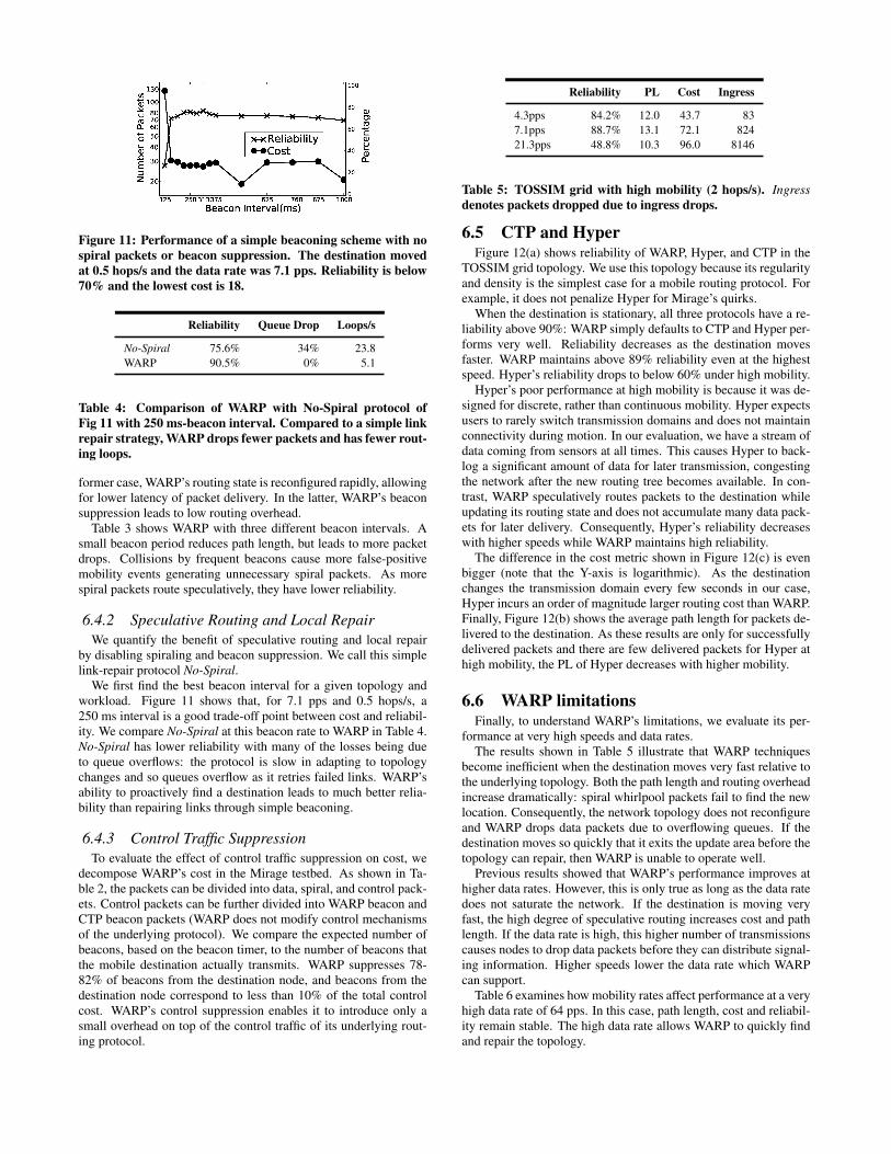
Figure 11: Performance of a simple beaconing scheme with nospiral packets or beacon suppression. The destination movedat 0.5 hops/s and the data rate was 7.1 pps. Reliability is below70% and the lowest cost is 18.
Reliability Queue Drop Loops/s
No-Spiral 75.6% 34% 23.8WARP 90.5% 0% 5.1
Table 4: Comparison of WARP with No-Spiral protocol ofFig 11 with 250 ms-beacon interval. Compared to a simple linkrepair strategy, WARP drops fewer packets and has fewer rout-ing loops.
former case, WARP’s routing state is reconfigured rapidly, allowingfor lower latency of packet delivery. In the latter, WARP’s beaconsuppression leads to low routing overhead.
Table 3 shows WARP with three different beacon intervals. Asmall beacon period reduces path length, but leads to more packetdrops. Collisions by frequent beacons cause more false-positivemobility events generating unnecessary spiral packets. As morespiral packets route speculatively, they have lower reliability.
6.4.2 Speculative Routing and Local RepairWe quantify the benefit of speculative routing and local repair
by disabling spiraling and beacon suppression. We call this simplelink-repair protocol No-Spiral.
We first find the best beacon interval for a given topology andworkload. Figure 11 shows that, for 7.1 pps and 0.5 hops/s, a250 ms interval is a good trade-off point between cost and reliabil-ity. We compare No-Spiral at this beacon rate to WARP in Table 4.No-Spiral has lower reliability with many of the losses being dueto queue overflows: the protocol is slow in adapting to topologychanges and so queues overflow as it retries failed links. WARP’sability to proactively find a destination leads to much better relia-bility than repairing links through simple beaconing.
6.4.3 Control Traffic SuppressionTo evaluate the effect of control traffic suppression on cost, we
decompose WARP’s cost in the Mirage testbed. As shown in Ta-ble 2, the packets can be divided into data, spiral, and control pack-ets. Control packets can be further divided into WARP beacon andCTP beacon packets (WARP does not modify control mechanismsof the underlying protocol). We compare the expected number ofbeacons, based on the beacon timer, to the number of beacons thatthe mobile destination actually transmits. WARP suppresses 78-82% of beacons from the destination node, and beacons from thedestination node correspond to less than 10% of the total controlcost. WARP’s control suppression enables it to introduce only asmall overhead on top of the control traffic of its underlying rout-ing protocol.
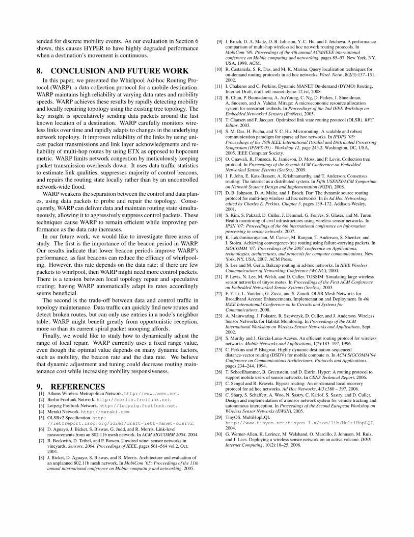
Reliability PL Cost Ingress
4.3pps 84.2% 12.0 43.7 837.1pps 88.7% 13.1 72.1 82421.3pps 48.8% 10.3 96.0 8146
Table 5: TOSSIM grid with high mobility (2 hops/s). Ingressdenotes packets dropped due to ingress drops.
6.5 CTP and HyperFigure 12(a) shows reliability of WARP, Hyper, and CTP in the
TOSSIM grid topology. We use this topology because its regularityand density is the simplest case for a mobile routing protocol. Forexample, it does not penalize Hyper for Mirage’s quirks.
When the destination is stationary, all three protocols have a re-liability above 90%: WARP simply defaults to CTP and Hyper per-forms very well. Reliability decreases as the destination movesfaster. WARP maintains above 89% reliability even at the highestspeed. Hyper’s reliability drops to below 60% under high mobility.
Hyper’s poor performance at high mobility is because it was de-signed for discrete, rather than continuous mobility. Hyper expectsusers to rarely switch transmission domains and does not maintainconnectivity during motion. In our evaluation, we have a stream ofdata coming from sensors at all times. This causes Hyper to back-log a significant amount of data for later transmission, congestingthe network after the new routing tree becomes available. In con-trast, WARP speculatively routes packets to the destination whileupdating its routing state and does not accumulate many data pack-ets for later delivery. Consequently, Hyper’s reliability decreaseswith higher speeds while WARP maintains high reliability.
The difference in the cost metric shown in Figure 12(c) is evenbigger (note that the Y-axis is logarithmic). As the destinationchanges the transmission domain every few seconds in our case,Hyper incurs an order of magnitude larger routing cost than WARP.Finally, Figure 12(b) shows the average path length for packets de-livered to the destination. As these results are only for successfullydelivered packets and there are few delivered packets for Hyper athigh mobility, the PL of Hyper decreases with higher mobility.
6.6 WARP limitationsFinally, to understand WARP’s limitations, we evaluate its per-
formance at very high speeds and data rates.The results shown in Table 5 illustrate that WARP techniques
become inefficient when the destination moves very fast relative tothe underlying topology. Both the path length and routing overheadincrease dramatically: spiral whirlpool packets fail to find the newlocation. Consequently, the network topology does not reconfigureand WARP drops data packets due to overflowing queues. If thedestination moves so quickly that it exits the update area before thetopology can repair, then WARP is unable to operate well.
Previous results showed that WARP’s performance improves athigher data rates. However, this is only true as long as the data ratedoes not saturate the network. If the destination is moving veryfast, the high degree of speculative routing increases cost and pathlength. If the data rate is high, this higher number of transmissionscauses nodes to drop data packets before they can distribute signal-ing information. Higher speeds lower the data rate which WARPcan support.
Table 6 examines how mobility rates affect performance at a veryhigh data rate of 64 pps. In this case, path length, cost and reliabil-ity remain stable. The high data rate allows WARP to quickly findand repair the topology.

(a) Reliability (b) Path length (c) Cost
Figure 12: TOSSIM grid experiments over varying speeds and at 21.3pps data rate. CTP, Hyper (HYP), and WARP (WR) resultsare shown.
Speed Reliability PL Cost
0hop/s(CTP) 36.1% 6.36 29.70.13hop/s 44.8% 6.56 27.60.17hop/s 46.4% 6.84 26.20.25hop/s 45.9% 6.85 27.30.5hop/s 42.1% 6.85 30.0
Table 6: TOSSIM grid: evaluation of WARP for high data rate(64 pps).
6.7 SummaryWARP is able to route packets to a highly mobile destination,
even when its motion is not continuous with the underlying connec-tivity. In continuous scenarios, simulation and testbed results showWARP’s delivery ratios as high as 99.7%, and do not drop below80%. WARP is able to quickly detect mobility through a com-bination of proactive (beacons) and reactive (data) mechanisms,but suppresses unnecessary beacons (roughly 80%) to reduce itsoverhead. WARP’s in-band signaling allows data packets to passthe few bits of needed control information, reducing control traf-fic needs further: WARP’s beacons constitute less than 10% of thecontrol cost. WARP’s speculative routing quickly finds new routes,while spiral packets constitute only a small portion of the over-all data traffic. Finally, collaborative and localized reconfigurationmeans that once new routes are found, spirals stop quickly.
7. RELATED WORKRouting in mobile ad-hoc networks (MANETs) has been an ac-
tive area of research for the past 15 years [25, 24, 13, 11]. Thesealgorithms, however, failed to achieve widespread adoption in realworld deployments. The complexity of the MANET problem –every node is mobile – is one reason for this disconnect: instead,MANET protocols are used in static meshes [3, 1, 2]. Perhaps amore significant factor in achieving high performance outside thesimpler world of simulation is the basic challenges of wireless byitself [6]. Even though mechanisms that improve reliability of wire-less communications are relatively well known, few protocols im-plement them in practice. Routing in a static mesh is a challengingenough problem by itself which has only begun to be solved effec-tively in the past few years [8, 15]: fully mobile ad-hoc networksremain an open and difficult problem.
WARP carefully monitors wireless links over time and rapidlyadapts to changes in the underlying network topology. It improvesreliability of the links by using unicast packet transmissions andlink layer acknowledgments and reliability of multi-hop routes byusing ETX as opposed to the hopcount metric. WARP limits net-
work congestion by meticulously keeping packet transmission over-heads down. It uses data traffic statistics to estimate link qualities,suppresses majority of control beacons, and repairs the routing statelocally rather than by an uncontrolled network-wide flood.
Clearly, WARP benefits by considering the narrower case of amobile node moving through a static mesh. However, in our expe-rience, existing protocols [11] fail entirely in these static mesh ex-periments with even a limited mobility of the sink. WARP is ableto use very simple mechanisms to achieve high packet delivery andlow cost in real as well as controlled mobility experiments.
One notable exception of wireless routing protocols used in prac-tice is OLSR [13]. It is used in community wireless mesh networksin Athens [1], Berlin [2], and Leipzig [3]. These are, however, notmobile ad-hoc networks as they consist of stationary nodes [22].Furthermore, these successful deployments change OLSR to useETX as the routing metric, rather than hopcount, an extension thatis part of the in-progress OLSRv2 specification [5].
WARP’s approach of using the datapath to maintain a routingtopology is similar to CTP’s datapath validation [15]. WARP takesCTP’s approach one step further. Where CTP uses data packets todetect when control plane updates are needed, WARP uses them toreplace control messages whenever possible through suppression.
WARP combines the ideas from AODV-LL [9] and MicroRout-ing [14] as a way to achieve both low cost and fast mobility detec-tion. It borrows the idea of link-layer feedback to detect destinationmobility from AODV-LL and proactive mobility discovery throughbeacons from MicroRouting.
WARP builds on the long history of local recovery research [14,20, 27, 10]. Like many of these local recovery schemes, WARP de-tects broken links, retrieves previously cached alternate routes, andinvalidates stale routes. Similar to AODV-BR [20], SLR [27], andquery localization [10], WARP limits the range over which nodessearch for a route. However, WARP differs from these approachesin that it actively probes and incrementally builds new routes with-out relying on a source or a destination to initiate route recovery.
WARP has intellectual similarities to consensus routing [16],which uses the notion of network-wide consensus to detect incon-sistencies and resort to backup routing schemes when needed. Butunlike consensus routing, which uses a controlled or periodic con-sensus mechanism, WARP is entirely decentralized and distributed,as its repairs are local.
In a similar vein, failure carrying packets [19] propose an ex-tension to link-state routing where packets contain routing failureinformation. Gateways route around failures through a periodic up-date of consensus on network state.
Finally, Hyper [26] is perhaps the most similar protocol to WARP,as it routes data from a static network to a mobile node. But unlikeWARP, which is designed for continuous mobility, HYPER is in-
tended for discrete mobility events. As our evaluation in Section 6shows, this causes HYPER to have highly degraded performancewhen a destination’s movement is continuous.
8. CONCLUSION AND FUTURE WORKIn this paper, we presented the Whirlpool Ad-hoc Routing Pro-
tocol (WARP), a data collection protocol for a mobile destination.WARP maintains high reliability at varying data rates and mobilityspeeds. WARP achieves these results by rapidly detecting mobilityand locally repairing topology using the existing tree topology. Thekey insight is speculatively sending data packets around the lastknown location of a destination. WARP carefully monitors wire-less links over time and rapidly adapts to changes in the underlyingnetwork topology. It improves reliability of the links by using uni-cast packet transmissions and link layer acknowledgments and re-liability of multi-hop routes by using ETX as opposed to hopcountmetric. WARP limits network congestion by meticulously keepingpacket transmission overheads down. It uses data traffic statisticsto estimate link qualities, suppresses majority of control beacons,and repairs the routing state locally rather than by an uncontrollednetwork-wide flood.
WARP weakens the separation between the control and data plan-es, using data packets to probe and repair the topology. Conse-quently, WARP can deliver data and maintain routing state simulta-neously, allowing it to aggressively suppress control packets. Thesetechniques cause WARP to remain efficient while improving per-formance as the data rate increases.
In our future work, we would like to investigate three areas ofstudy. The first is the importance of the beacon period in WARP.Our results indicate that lower beacon periods improve WARP’sperformance, as fast beacons can reduce the efficacy of whirlpool-ing. However, this rate depends on the data rate; if there are fewpackets to whirlpool, then WARP might need more control packets.There is a tension between local topology repair and speculativerouting; having WARP automatically adapt its rates accordinglyseems beneficial.
The second is the trade-off between data and control traffic intopology maintenance. Data traffic can quickly find new routes anddetect broken routes, but can only use entries in a node’s neighbortable; WARP might benefit greatly from opportunistic reception,more so than its current spiral packet snooping affords.
Finally, we would like to study how to dynamically adjust therange of local repair. WARP currently uses a fixed range value,even though the optimal value depends on many dynamic factors,such as mobility, the beacon rate and the data rate. We believethat dynamic adjustment and tuning could decrease routing main-tenance cost while increasing mobility responsiveness.
9. REFERENCES[1] Athens Wireless Metropolitan Network. http://www.awmn.net.[2] Berlin Freifunk Network. http://berlin.freifunk.net.[3] Leipzig Freifunk Network. http://leipzig.freifunk.net.[4] Meraki Network. http://meraki.com.[5] OLSRv2 Specification. http:
//ietfreport.isoc.org/idref/draft-ietf-manet-olsrv2.[6] D. Aguayo, J. Bicket, S. Biswas, G. Judd, and R. Morris. Link-level
measurements from an 802.11b mesh network. In ACM SIGCOMM 2004, 2004.[7] R. Beckwith, D. Teibel, and P. Bowen. Unwired wine: sensor networks in
vineyards. Sensors, 2004. Proceedings of IEEE, pages 561–564 vol.2, Oct.2004.
[8] J. Bicket, D. Aguayo, S. Biswas, and R. Morris. Architecture and evaluation ofan unplanned 802.11b mesh network. In MobiCom ’05: Proceedings of the 11thannual international conference on Mobile computin g and networking, 2005.
[9] J. Broch, D. A. Maltz, D. B. Johnson, Y.-C. Hu, and J. Jetcheva. A performancecomparison of multi-hop wireless ad hoc network routing protocols. InMobiCom ’98: Proceedings of the 4th annual ACM/IEEE internationalconference on Mobile computing and networking, pages 85–97, New York, NY,USA, 1998. ACM.
[10] R. Castan̈eda, S. R. Das, and M. K. Marina. Query localization techniques foron-demand routing protocols in ad hoc networks. Wirel. Netw., 8(2/3):137–151,2002.
[11] I. Chakeres and C. Perkins. Dynamic MANET On-demand (DYMO) Routing.Internet-Draft, draft-ietf-manet-dymo-12.txt, 2008.
[12] B. Chun, P. Buonadonna, A. AuYoung, C. Ng, D. Parkes, J. Shneidman,A. Snoeren, and A. Vahdat. Mirage: A microeconomic resource allocationsystem for sensornet testbeds. In Proceedings of the 2nd IEEE Workshop onEmbedded Networked Sensors (EmNets), 2005.
[13] T. Clausen and P. Jacquet. Optimized link state routing protocol (OLSR). RFCEditor, 2003.
[14] S. M. Das, H. Pucha, and Y. C. Hu. Microrouting: A scalable and robustcommunication paradigm for sparse ad hoc networks. In IPDPS ’05:Proceedings of the 19th IEEE International Parallel and Distributed ProcessingSymposium (IPDPS’05) - Workshop 12, page 245.2, Washington, DC, USA,2005. IEEE Computer Society.
[15] O. Gnawali, R. Fonseca, K. Jamieson, D. Moss, and P. Levis. Collection treeprotocol. In Proceedings of the Seventh ACM Conference on EmbeddedNetworked Sensor Systems (SenSys), 2009.
[16] J. P. John, E. Katz-Bassett, A. Krishnamurthy, and T. Anderson. Consensusrouting: The internet as a distributed system. In Fifth USENIX/ACM Symposiumon Network Systems Design and Implementation (NSDI), 2008.
[17] D. B. Johnson, D. A. Maltz, and J. Broch. Dsr: The dynamic source routingprotocol for multi-hop wireless ad hoc networks. In In Ad Hoc Networking,edited by Charles E. Perkins, Chapter 5, pages 139–172. Addison-Wesley,2001.
[18] S. Kim, S. Pakzad, D. Culler, J. Demmel, G. Fenves, S. Glaser, and M. Turon.Health monitoring of civil infrastructures using wireless sensor networks. InIPSN ’07: Proceedings of the 6th international conference on Informationprocessing in sensor networks, 2007.
[19] K. Lakshminarayanan, M. Caesar, M. Rangan, T. Anderson, S. Shenker, andI. Stoica. Achieving convergence-free routing using failure-carrying packets. InSIGCOMM ’07: Proceedings of the 2007 conference on Applications,technologies, architectures, and protocols for computer communications, NewYork, NY, USA, 2007. ACM Press.
[20] S. Lee and M. Gerla. Bakcup routing in ad-hoc networks. In IEEE WirelessCommunications of Networking Conference (WCNC), 2000.
[21] P. Levis, N. Lee, M. Welsh, and D. Culler. TOSSIM: Simulating large wirelesssensor networks of tinyos motes. In Proceedings of the First ACM Conferenceon Embedded Networked Sensor Systems (SenSys), 2003.
[22] F. Y. Li, L. Vandoni, G. Zicca, and S. Zanoli. OLSR Mesh Networks forBroadband Access: Enhancements, Implementation and Deployment. In 4thIEEE International Conference on In Circuits and Systems forCommunications, 2008.
[23] A. Mainwaring, J. Polastre, R. Szewczyk, D. Culler, and J. Anderson. WirelessSensor Networks for Habitat Monitoring. In Proceedings of the ACMInternational Workshop on Wireless Sensor Networks and Applications, Sept.2002.
[24] S. Murthy and J. Garcia-Luna-Aceves. An efficient routing protocol for wirelessnetworks. Mobile Networks and Applications, 1(2):183–197, 1996.
[25] C. Perkins and P. Bhagwat. Highly dynamic destination-sequenceddistance-vector routing (DSDV) for mobile compute rs. In ACM SIGCOMM’94Conference on Communications Architectures, Protocols and Applications,pages 234–244, 1994.
[26] T. Schoellhammer, B. Greenstein, and D. Estrin. Hyper: A routing protocol tosupport mobile users of sensor networks. In CENS Technical Report, 2006.
[27] C. Sengul and R. Kravets. Bypass routing: An on-demand local recoveryprotocol for ad hoc networks. Ad Hoc Networks, 4(3):380 – 397, 2006.
[28] C. Sharp, S. Schaffert, A. Woo, N. Sastry, C. Karlof, S. Sastry, and D. Culler.Design and implementation of a sensor network system for vehicle tracking andautonomous interception. In Proceedings of the Second European Workshop onWireless Sensor Networks (EWSN), 2005.
[29] TinyOS. MultiHopLQI.http://www.tinyos.net/tinyos-1.x/tos/lib/MultiHopLQI,2004.
[30] G. Werner-Allen, K. Lorincz, M. Welshand, O. Marcillo, J. Johnson, M. Ruiz,and J. Lees. Deploying a wireless sensor network on an active volcano. IEEEInternet Computing, 10(2):18–25, 2006.