Whirl Tower Demonstrations of the SHARCS Hybrid … Tower Demonstrations of the SHARCS Hybrid...
13
Whirl Tower Demonstrations of the SHARCS Hybrid Control Concept Daniel Feszty Fred Nitzsche Andrei Mander Assistant Professor Professor Research Student [email protected] [email protected] [email protected] Department of Mechanical and Aerospace Engineering Carleton University Ottawa, ON, Canada Giuliano Coppotelli Fabio Vetrano Associate Professor Research Student [email protected] [email protected] Department of Aerospace Engineering and Astronautics Universit`a di Roma “La Sapienza” Rome, Italy Johannes Riemenschneider Peter Wierach Research Scientist Department Head for Multifunctional Materials [email protected] [email protected] Institute of Composite Structures and Adaptive Systems German Aerospace Center (DLR) Braunschweig, Germany Abstract Elements of the SHARCS (Smart Hybrid Active Rotor Control System) Hybrid Control concept are demonstrated via two sets of whirl tower tests. Hybrid Control stands for combining a flow control (such as an Actively Controlled Flap or Active Twist Rotor) and of a structural (or stiffness) control device on a helicopter blade. A Hybrid Control system promises to reduce vibration and noise on helicopters simultaneously as well as to improve the efficiency of the flow control device. For the structural control system, a unique and entirely original Active Pitch Link has been developed at Carleton University, which is capable of dynamically controlling the torsional stiffness of a blade. Design, prototyping, static and whirl tower testing of this device is presented in the paper. A second set of whirl tower tests of an Active Twist Rotor equipped with a range of springs instead of the conventional pitch link, demonstrates that the Active Pitch Link shall indeed be capable of lowering the torsional stiffness of the blade. For these tests, the modal parameters of the blade were evaluated via a novel “Output-Only” method, which represents the first application of such methodology for rotary-wing applications. Presented at the American Helicopter Society 65 th Annual Forum, Grapevine, Texas, May 27-29, 2009. Copyright © 2009 by the American Helicopter Society International Inc. All rights reserved.
Transcript of Whirl Tower Demonstrations of the SHARCS Hybrid … Tower Demonstrations of the SHARCS Hybrid...
Whirl Tower Demonstrations of the SHARCS Hybrid Control Concept
Daniel Feszty Fred Nitzsche Andrei Mander Assistant Professor Professor Research Student [email protected] [email protected] [email protected]
Department of Mechanical and Aerospace Engineering
Carleton University
Ottawa, ON, Canada
Giuliano Coppotelli Fabio Vetrano Associate Professor Research Student
[email protected] [email protected]
Department of Aerospace Engineering and Astronautics
Universit`a di Roma “La Sapienza”
Rome, Italy
Johannes Riemenschneider Peter Wierach Research Scientist Department Head for Multifunctional Materials
[email protected] [email protected]
Institute of Composite Structures and Adaptive Systems German Aerospace Center (DLR)
Braunschweig, Germany
Abstract
Elements of the SHARCS (Smart Hybrid Active Rotor Control System) Hybrid Control concept are demonstrated via two sets of whirl tower tests. Hybrid Control stands for combining a flow control (such as an Actively Controlled Flap or Active Twist Rotor) and of a structural (or stiffness) control device on a helicopter blade. A Hybrid Control system promises to reduce vibration and noise on helicopters simultaneously as well as to improve the efficiency of the flow control device. For the structural control system, a unique and entirely original Active Pitch Link has been developed at Carleton University, which is capable of dynamically controlling the torsional stiffness of a blade. Design, prototyping, static and whirl tower testing of this device is presented in the paper. A second set of whirl tower tests of an Active Twist Rotor equipped with a range of springs instead of the conventional pitch link, demonstrates that the Active Pitch Link shall indeed be capable of lowering the torsional stiffness of the blade. For these tests, the modal parameters of the blade were evaluated via a novel “Output-Only” method, which represents the first application of such methodology for rotary-wing applications.
Presented at the American Helicopter Society 65th Annual Forum, Grapevine, Texas, May 27-29, 2009. Copyright © 2009 by the American Helicopter Society International Inc. All rights reserved.
Introduction In the past two decades, various active control systems have been proposed for reducing vibration and/or noise on helicopters [1-7]. These systems can be classified into either fuselage-based or rotor-based systems [7]. Fuselage-based systems are easier to install, but they are less efficient in controlling vibration since they cannot tackle vibration at its source - on the rotor blades. In other words, they can only aim at reducing the original or baseline level of vibration already transferred to the fuselage through the pitch links and the shaft. In contrast, rotor-based systems have the ability to control vibration at its source - on the rotor blades - and thus have seen great deal of interest recently in the rotorcraft community. The most popular rotor-based system nowadays, and the primary candidate for a possible production application - is the Actively Controlled Flap (ACF) [1][2][6][8][9]. This system was pioneered by Eurocopter and the first flight test of a helicopter with ACF was accomplished in September 2005 [6]. Currently, there are at least half a dozen other research teams investigating the feasibility of ACF control for helicopters [1][2][6][8-12]. An important aspect of the ACF control is the mode of operation of the flap: it has been identified that the ACF can work in two modes: in either the high-lift mode or servo-elastic mode [2][9]. Based on numerical simulations, the servo-elastic mode would be preferred since it promises to reduce vibration better than the high-lift mode. For operating the flap in a servo-elastic mode, one would like to have as low as possible torsional stiffness of the blade. Another relatively popular rotor-based control system is the Active Twist Rotor (ATR). The disadvantage of this system is the relatively high power consumption and the relatively low controllable twist (typically 2-3 degrees over the length of the blade) [5]. On the other hand, the blade design and maintenance is simpler than that for the ACF. Again, a soft blade in torsion would be desirable to increase the efficiency of the ATR control system. Unfortunately, to design a rotor blade with low torsional stiffness is not an option: the blade modal frequencies - which are directly linked to the blade stiffness - need to fit into a narrow range (typically around 6/rev at the nominal RPM) in order to avoid resonance problems with other parts of the rotor. Thus, the only solution appears to be to adaptively change the torsional stiffness of the blade, which, however, represents a so far unsolved design problem. In fact, a number of researchers have shown computationally that lowering the blade torsional stiffness at the root would be beneficial for reducing vibration [13-16]. However, no concrete design or prototype of structural (or stiffness) control actuator has been proposed to date.
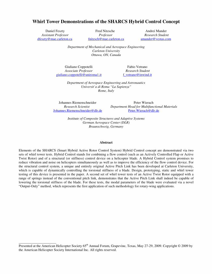
Carleton University has been working on developing such structural control technology for a number of years as part of the SHARCS (Smart Hybrid Active Rotor Control System) project [17][18]. The main goal of the project is to demonstrate the feasibility of a "Hybrid Control” system, in which a flow control (such as the ACF or ATR) and a structural control device are simultaneously employed on each blade. For the structural control device, an Active Pitch Link (APL) has been proposed [16][19], which is a semi-active impedance control system capable of controlling the blade torsional stiffness (Fig.1).
Fig. 1. The SHARCS hybrid concept with 3 individual feedback systems.
The advantages of a Hybrid Control system, i.e. of employing a structural control system and a flow control system are twofold: 1) It has the potential to reduce vibration and noise
simultaneously. This is realized by meeting the multiple control objectives of reducing noise and vibration by employing multiple control systems at the same time, which is a common theorem of control theory. 2) It promises to improve the efficiency of vibration
reduction. This is because the structural control system (APL) has the ability to adaptively change the torsional stiffness of the blade, thus allowing to operate a flow control device, which would require low torsional stiffness (e.g. the Actively Controlled Flap in the servo tab mode, or an Active Twist Rotor), to operate more efficiently. The present paper focuses on demonstrating the second point via whirl tower tests, i.e. the improvement of the efficiency of a flow control device for vibration reduction. The design of the first ever working prototype of a solely electrically driven structural control device for torsional stiffness control will be presented first, followed by experimental evidence of its operation under static and centrifugal conditions.
Actively Controlled Tip (ACT)
Actively Controlled Flap (ACT)
Actively Pitch Link (APL)

Operating Principle
The principle of the Active Pitch Link is summarized in Fig. 2. Note that this configuration does not correspond to the actual APL design for the SHARCS rotor, but it is better suited to illustrate the general operating principle. In Fig. 2, two springs, k1 and k2 have the ends attached to the opposite walls and a pair of sleeves that can slide one with respect to the other. An external (input) force F is applied to the sleeve attached to the spring designated by k2. A stack of piezoelectric actuators is inserted into the internal sleeve attached to the spring designated by k1. When the actuator is “OFF”, the two sleeves can move freely and the resulting horizontal displacement (output) is
max 2F kδ = . Spring k2 is designed to be the “primary”
load path of the APL. When the actuator is turned “ON”, the
Fig. 2. Sketch of the APL system concept (not actual design).
internal sleeve under the action of the stack of piezoelectric yields and applies on the external sleeve a resultant normal force, N. A friction force, µN is induced by the contact between the two surfaces. If this friction force is sufficiently large and the two sleeves are forced into motion together, an arrangement of two springs in series is created and a smaller
horizontal output displacement ( )min 1 2F k kδ = + is
obtained because the stiffness “seen” by the input force rises
from the system’s original k2 to 1 2k k+ . In fact, the spring
designated by k1 is driven by the resultant friction force µN applied by the internal sleeve on the external sleeve, which is controlled by the external electrical stimulus (control input). This spring is called the “secondary” path of the APL. Thus, the horizontal output displacement of the system under the input force F varies between the referred two extremes, ( )1 2 2F k k F kδ+ ≤ ≤ and the total load is
distributed between the primary and the secondary load paths. Due to manufacturing tolerances and piezoelectric limitations, the latter two limits may not even be achievable since the maximum stroke supplied by the stack of piezoelectric elements might be insufficient to guarantee that
the two sleeves move freely in the actuator “OFF” condition and/or the piezoelectric force is not sufficient to guarantee a locked situation between the two sleeves in the “ON” condition. However, this is not regarded as an important issue because the fundamental concept resides solely on the ability of the system to change in real time its apparent stiffness characteristics. Note that the APL system also changes its apparent mass because the piezoelectric stack and internal sleeve have inertial properties. However, this effect can be disregarded if the overall system is “stiffness dominated” (i.e., the harmonic disturbance force has a frequency much lower than the internal resonance frequencies of the APL). The dry friction between the sleeves also creates coulomb damping, which cannot be neglected. The latter adds an important stabilizing effect to the system. Since the APL actively changes both its apparent mass and stiffness and also its internal damping, it is called an “impedance control” device. Within the context of the SHARCS project, the APL shall replace the conventional pitch link. Thus, the blade and the APL become an integral system, which can control the twist impedance of the blade in real time. For this, the 1st torsional mode of the blade is targeted for the control action.
Expected Performance
The beneficial effect of varying the stiffness at the blade root for controlling helicopter vibration loads was verified independently in Refs. [13-16][18]. All simulations were performed on aeroelastic models incorporating a complete rotor blade system. Two examples of these feasibility studies, showing the beneficial effects of using an APL on its own (the combined effect of APL and ACF is yet to be simulated), are shown in Figs. 3 and 4. The former one was performed via the Smartrotor code [20] at Carleton University [16], while the latter one by the University of Rome 3 [18]. They both indicate that a device capable of altering the pitch link stiffness – and via that the blade root stiffness - can significantly reduce vibration.
Fig. 3. Time history of the vertical hub loads for a SHARCS forward flight case with APL “off” (solid line) and APL “on” (dashed line). Smartrotor simulation performed by Carleton University [16].
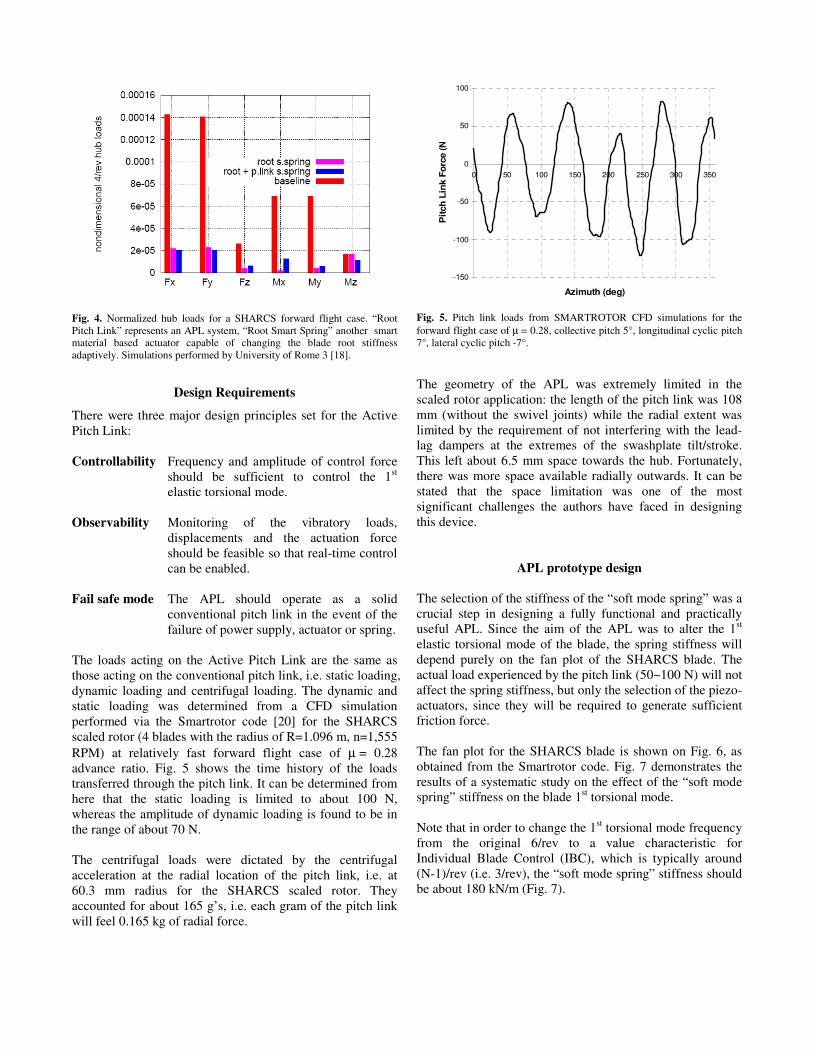
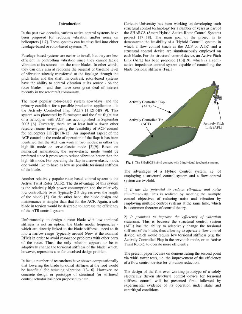
Fig. 4. Normalized hub loads for a SHARCS forward flight case. “Root Pitch Link” represents an APL system, “Root Smart Spring” another smart material based actuator capable of changing the blade root stiffness adaptively. Simulations performed by University of Rome 3 [18].
Design Requirements
There were three major design principles set for the Active Pitch Link: Controllability Frequency and amplitude of control force
should be sufficient to control the 1st elastic torsional mode.
Observability Monitoring of the vibratory loads,
displacements and the actuation force should be feasible so that real-time control can be enabled.
Fail safe mode The APL should operate as a solid
conventional pitch link in the event of the failure of power supply, actuator or spring.
The loads acting on the Active Pitch Link are the same as those acting on the conventional pitch link, i.e. static loading, dynamic loading and centrifugal loading. The dynamic and static loading was determined from a CFD simulation performed via the Smartrotor code [20] for the SHARCS scaled rotor (4 blades with the radius of R=1.096 m, n=1,555 RPM) at relatively fast forward flight case of µ = 0.28 advance ratio. Fig. 5 shows the time history of the loads transferred through the pitch link. It can be determined from here that the static loading is limited to about 100 N, whereas the amplitude of dynamic loading is found to be in the range of about 70 N. The centrifugal loads were dictated by the centrifugal acceleration at the radial location of the pitch link, i.e. at 60.3 mm radius for the SHARCS scaled rotor. They accounted for about 165 g’s, i.e. each gram of the pitch link will feel 0.165 kg of radial force.
-150
-100
-50
0
50
100
0 50 100 150 200 250 300 350
Azimuth (deg)
Pit
ch
Lin
k F
orc
e (
N)
Fig. 5. Pitch link loads from SMARTROTOR CFD simulations for the forward flight case of µ = 0.28, collective pitch 5°, longitudinal cyclic pitch 7°, lateral cyclic pitch -7°.
The geometry of the APL was extremely limited in the scaled rotor application: the length of the pitch link was 108 mm (without the swivel joints) while the radial extent was limited by the requirement of not interfering with the lead-lag dampers at the extremes of the swashplate tilt/stroke. This left about 6.5 mm space towards the hub. Fortunately, there was more space available radially outwards. It can be stated that the space limitation was one of the most significant challenges the authors have faced in designing this device.
APL prototype design
The selection of the stiffness of the “soft mode spring” was a crucial step in designing a fully functional and practically useful APL. Since the aim of the APL was to alter the 1st elastic torsional mode of the blade, the spring stiffness will depend purely on the fan plot of the SHARCS blade. The actual load experienced by the pitch link (50~100 N) will not affect the spring stiffness, but only the selection of the piezo-actuators, since they will be required to generate sufficient friction force. The fan plot for the SHARCS blade is shown on Fig. 6, as obtained from the Smartrotor code. Fig. 7 demonstrates the results of a systematic study on the effect of the “soft mode spring” stiffness on the blade 1st torsional mode. Note that in order to change the 1st torsional mode frequency from the original 6/rev to a value characteristic for Individual Blade Control (IBC), which is typically around (N-1)/rev (i.e. 3/rev), the “soft mode spring” stiffness should be about 180 kN/m (Fig. 7).

0.0
20.0
40.0
60.0
80.0
100.0
120.0
140.0
160.0
10 30 50 70 90 110 130 150 170
Rotor speed (rad/s)
Fre
quency (
Hz)
1/rev
7/rev6/rev
5/rev
4/rev
3/rev
2/rev
1st torsion
2nd flap
1st flap
1st lead/lag
rigid lead/lag
rigid flap
Fig. 6. Fan plot for the SHARCS blade.
Fig. 7. Effect of pitch link stiffness on the first elastic torsion modal frequency. The APL prototype is designed to continuously change its axial stiffness between 180 kN/m (“soft” mode) and infinity (“solid” mode, nominal condition).
The actuators were selected to provide sufficient normal force (N in Fig. 2) to create friction (µN in Fig. 2) capable of overcoming the maximum vertical force through the pitch link (100 N). Also, the actuator frequency was required to be at least (N+1)/rev (i.e. 5/rev for the SHARCS rotor), which is the typical upper limit for IBC type control. For the APL prototype, a pair of Piezomechanik Pst 150/7/40 VS12 piezoelectric actuators has been selected with a maximum block force of 1,800 N and maximum frequency of 200 Hz. A design fulfilling all the requirements set above, i.e. controllability, observeability, Fail Safe design, size requirements, load requirements, and also incorporating the selected spring stiffness and actuators was developed after numerous iterations at Carleton University. Note that in order to fulfill the Fail Safe design requirement, springs k1 and k2 were incorporated in parallel rather than in series as it was illustrated in Fig. 2.
Fig. 8. The Active Pitch Link prototype manufactured at Carleton University.
By this, the overall system stiffness can be varied between k1 (“soft” link) and k2 (“solid” link), instead of the ranges of k2 and k1+k2 as in Fig. 2. The design incorporates a number of clever and matured design solutions yielding compactness, friction force independence from centrifugal loads, adjustable preload levels and default inclusion of various sensors. A picture of the prototype is shown in Fig. 8. Note that the total mass of this unit is 196 g. If the APL damping characteristics would change in time due to the wear of contacting parts or temperature increase, the control algorithm would be able to self-compensate for these changes. Most importantly, however, the modal characteristics of the blade first elastic torsion mode shape, especially its frequency (due to the active changes in the APL apparent stiffness) and damping ratio (due to the APL internal friction) are controllable. The APL controller is called “semi-active” or “indirect-active” because all control energy is directed to change the dynamic properties of the structure (the blade impedance) rather than to generate mechanical work against external aerodynamic forces. For this reason, the power consumption is low in comparison to other IBC concepts such as the Active Twist Rotor (ATR), where the piezoelectric elements need to act against the total aerodynamic moment applied on the blade. As a comparison, to reach its objectives, the APL system needs about 100 V peak-to-peak control voltage, about 3-5% of the value required by the ATR. The manufacturing and maintenance costs of an APL system are also very little when compared to those of an ATR. Maintenance is also easy since the friction elements are easily reachable and replaceable.
0
1
2
3
4
5
6
7
0 200 400 600 800 1000 1200 1400 1600 1800 2000
Pitch Link Stiffness (kN/m)
1s
t T
ors
ion
Eig
en
fre
qu
en
cy
(/r
ev
)
“Soft” mode stiffness
“Solid” mode stiffness

The prototype also incorporates a default set of sensors to facilitate “observeability” of the device. The list below shows the installation requirements for the APL per one blade.
- Hall Effect sensor Honywell, SS495: 1 - Accelerometers PCB, 352A24 or 352C22: 2 - Load cell PCB, 201A76: 1 - Piezo-actuators PSt 150/7/40 VS12: 2 - Amplifier Piezomechanik LE 150/200-2: 1
Fig. 9 shows the arrangement of the above set of sensors on the APL.
Fig. 9. Sensor locations on APL.
Modes of operation
Based on the selected “soft mode spring” stiffness of 180 kN/m and the actuator employed (0-150 V power range), the “desired” stiffness characteristic, shown on Fig. 10, could be constructed for the Active Pitch Link. In the “solid link” mode, the control voltage on the piezo-actuator is in the range of approximately 0~60 V. The friction pad is completely stacked due to the preloading mechanism and thus the load is carried through the “primary (solid) load path” (Fig. 10) and the stiffness of the APL is virtually infinite, i.e. it behaves as a regular solid pitch link. In the “transition” mode, the control voltage on the piezo-actuator is in the range of approximately 60~120 V. This is the mode in which the normal force (N in Fig. 2) can be actively controlled. The controllable friction enables to actively control the damping by capitalizing on extracting energy from the system via friction [21]. In the “soft link” mode, the control voltage on the piezo-actuator is in the range of approximately 120~150 V, i.e. just within the maximum possible limit of 160 V for the selected type of piezo-actuator. The friction pad is released completely and the APL stiffness becomes k=180 kN/m, the level targeted for the active control of the 1st elastic torsional mode of the blade. In the event of failure, the APL returns to Fail Safe “solid link” mode.
Fig.10. Theoretical modes of operation of the Active Pitch Link.

Static Testing
Static testing of the APL has been completed at Carleton University. A special test jig was designed and built for this purpose, which was able to reproduce the amplitude and frequency of the loads acting on the APL. These loads were generated by a shaker and transmitted to the APL via an adjustable moment arm (Fig. 11).
Shaker
Shaker force
Simulated pitch link load
Moment arm
APL actuator under the load conditions
Fig. 11. APL static test jig.
A control signal from the range of 0~150 V was applied in both sinusoidal form (frequency range up to 220 Hz) and pulse form (frequency range up to 150 Hz). The power electronics (amplifier Piezomechanik LE 150/200-2) was able to deliver the total capacitance load of 10.8 mF in the working frequency range without any signal degradation, time delays or significant shape change. The piezo-actuators worked perfectly even in the pulse mode under variable load conditions. More details are available in Ref. [19]. Finally, the performance of the APL as a device capable of controlling stiffness was actively tested under various axial load conditions ranging from 5 N to 120 N and 1 Hz to 220 Hz in frequency. Summary of the experimental results is shown in Fig. 12. The linearity of the experimental characteristics in the transition (Zone 2) indicates that there is excellent opportunity for reliable control of damping and therefore usage of the “energy extraction” mode [21]. Note that the experimental results are very close to the expected theoretical line.
Fig. 12. APL stiffness variation with applied voltage – comparison of the experimental (black)
and theoretical results (blue).

Whirl Tower testing of APL For whirl tower testing of the Active Pitch Link, a special test jig had to be developed to reproduce the vibratory loads typical of forward flight. Note that in a whirl tower - in the lack of the “wind” representing forward flight - it is normally impossible to generate pitch link vibrations via aerodynamic loads. Thus, a test jig reproducing the desired vibratory loads mechanically has been constructed as shown in Fig. 13. This incorporates a large powerful piezo-stack actuator from Sensortech, Collingwood, ON, Canada (type SJ12-70-1010-00), which, when combined through the moment arm to the pitch link, shall be capable of generates the typical vibratory loads experienced by the pitch link. The frequency and amplitude of these loads could be altered via the real-time control of the voltage applied to the piezo-stack actuators. Since within this test jig, the APL was located at a much larger radius than on the actual wind tunnel model (725 mm instead of 60.3 mm) the rotational speed has been adjusted to 410 RPM instead of 1,555 RPM to achieve the appropriate centrifugal loads on the pitch link.
The centrifugal tests were conducted at the DLR Braunschweig (German Aerospace Center) whirl tower facility [22] in Germany (Fig. 14). This features a 30kW DC shunt-wound motor and a balance weight - mounted on the opposite side of the rotating specimen – which allowed to trim the whole rotating system at different (clockwise) rotating speed. The data transfer was realized by 24 slip rings and by an additional telemetry system with 12 channels available for strain gauge measurements (full bridge or half bridge – none used for these particular tests) and 4 ICP channels for acceleration sensors. A camera, installed in the
test room allowed permanent monitoring of the experiment from the control room. The results of the whirl tower tests are summarized in Fig. 14. It can be seen that even under centrifugal loads, the 3 operational modes of “solid link”, “transition” and “soft link” could be achieved by the APL. Note that for the same resultant stiffness, higher actuation voltage was required in the dynamic tests than in the static case. This is probably due to the effect of the centrifugal loads acting on the friction pad of the actuator mechanism. Also note that due to the design constraints set by the Sensortech piezoelectric actuators (used for producing the vibratory loads) the amplitude of vibration was only 10 N in the dynamic tests in contrast to 50 N in the static tests. Nevertheless, this still proved to be enough to detect noticeable displacements from which the resultant stiffness could be deduced.
To rotor hub
Piezoactuator force
Simulated pitch link load
Piezoactuator
Centrifugal load
Moment arm
Fig. 13. Whirl Tower test jig designed for reproducing the vibratory loads acting on the APL.
APL actuator

20 40 60 80 100 120 140 160 180Control voltage on piezo actuator Uc, volt
0
100
200
300
400
500
600
700
800
AP
L s
tiff
ness K
, kN
/ m
Virtual infinity level
Targeted SOFT stiffness level k=180 KN / m
Zone 1. SOLID link zone Zone 2. TRANSITION zone Zone 3. SOFT link zone
axial force Fload=50 N f=200Hx
Text
Text
Maxim
um
voltage level U
max=150 v
20 40 60 80 100 120 140 160 180Control voltage on piezo actuator Uc, volt
0
100
200
300
400
500
600
700
800
AP
L s
tiff
ness K
, kN
/ m
Virtual infinity level
Targeted SOFT stiffness level k=180 kN/m
Zone 1. SOLID link zone Zone 2. TRANSITION zone Zone 3. SOFT link zone
Dynamic test: rotational speed 410 rpm,load force 10 N f=50 Hz
Theorethical ideal stiffness
Fig. 14. The APL test jig mounted on the DLR rotor head.
Fig. 15. APL stiffness variation as a function of the control voltage under static and centrifugal loads.
Moment arm
Piezo-actuators for
generating vibration
Active Pitch Link
Balance weight
High-voltage
slip rings
Low-voltage
slip rings
Telemetry system
Static test:.load force 10 N f=50 Hz

Whirl tower testing of blade stiffness control The second set of whirl tower tests aimed at demonstrating that the Active Pitch Link can indeed control the torsional stiffness of a blade in rotation. For this, the Active Twist Blade (ATB) blade of DLR Braunschweig was used, which is a 1:2.5 scaled model of a BO-105 blade with Micro Fibre Composite (MFC) actuator active twist technology [22]. The reason for using an Active Twist Rotor blade for these tests was its capability to generate a perturbation signal by actuating the MFC actuators. From the response to this signal, the blade stiffness characteristics can then be determined. However, this classical “Input – Output” type method was only intended to be used as a “backup” for the more elegant and novel “Output-Only” methods brought into the project by the University of Rome “La Sapienzia”. “Output-Only” methods for identifying the modal parameters of a structure include the Frequency Domain Decomposition (FDD) method [23], the Stochastic Subspace Identification (SSI) based Balance Realization method (BR) [24][25], and the Hilbert Transform Method (HTM) [26]. These techniques have already been proven in different engineering disciplines such as civil, aerospace and maritime engineering [27, 28], however – to the knowledge of the authors – these tests were the first ones to demonstrate their application to rotating blades. “Output-only” methods all share the idea of the perturbations being generated via the aerodynamics (turbulence and/or interference effects) and dynamics (slight imperfections in rotor balancing), which are assumed to be sufficient to randomly excite the structure both in time and space so that the structural modes of interest are well energized. This is a very strong hypothesis for the experimental activity carried out in this paper. Indeed, the vibrations for a rotating blade are not really random since they typically appear as the multiples of the frequency of rotational speed. Therefore, the vibrations measured during rotating tests cannot truly be considered as pure white noise excitation, and as such the “Output-Only” procedures should not be applicable in these working conditions. Although several techniques have been recently proposed to overcome this difficulty [29][30][31], the authors of this paper choose not to consider this (otherwise very important) effect in this
work. Instead, particular attention was paid to distinguish real structural vibrations from noise and excitation contributions. The results of the specific research activity concerning the harmonic load identification will be presented in a further paper. Another drawback of these techniques is that the resulting modal parameters could not be used in synthesis problems because the participation factors are unknown due to the lack of the measurement of the input loading: therefore, the generalized parameters could not be estimated. Nevertheless, this problem has been solved by performing different experimental tests, as reported in Refs. [32][33][34]. The geometry of the Active Twist Blade is shown in Fig. 16. The torsional deformation of the blade was measured in 6 spanwise locations by two strain gauges arranged on the opposite sides of the upper and lower blade shell in an angle of ±45o degree. The sensors, and their necessary wirings, were embedded into the blade skin during the manufacturing process, and were connected in full bridge to compensate for any bending deformation of the blade. In addition, the blade was equipped with 3 sets of strain gages to record the flapwise bending deformation. Two additional accelerometers were mounted at the leading and trailing edge of the blade tip, respectively, used to directly measure twist angle because this information was not available from the strain gages measurements. Furthermore, a supplementary optical measurement system was installed as a backup to check the recordings from both the strain gages and the acceleration sensors. This system consisted of a stationary high speed camera synchronized with two LEDs attached at the leading and the trailing edge of the rotor blade tip. This allowed the visualization of the torsional deformation of the blade by identifying the spatial positions of the two light spots of the LEDs and by properly triggering the camera. The capability of the Active Pitch Link to alter the dynamic properties of the rotating blade was demonstrated by replacing the conventional pitch link simply by a spring representing the resultant stiffness of the APL (Fig. 17).
Fig. 16. Location of sensors on the DLR Active Twist Blade, which was used for the 2nd set of whirl tower tests.
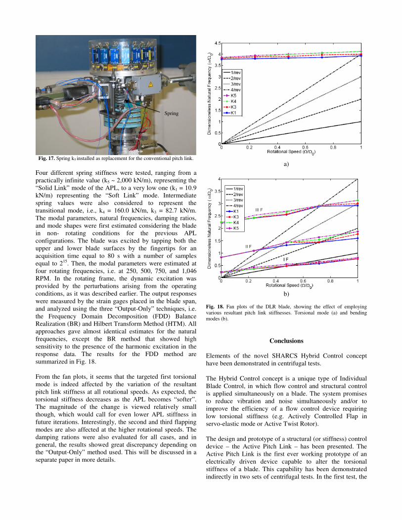
Fig. 17. Spring k5
installed as replacement for the conventional pitch link.
Four different spring stiffness were tested, ranging from a practically infinite value (k5 ~ 2,000 kN/m), representing the “Solid Link” mode of the APL, to a very low one (k1 = 10.9 kN/m) representing the “Soft Link” mode. Intermediate spring values were also considered to represent the transitional mode, i.e., k4 = 160.0 kN/m, k3 = 82.7 kN/m. The modal parameters, natural frequencies, damping ratios, and mode shapes were first estimated considering the blade in non- rotating conditions for the previous APL configurations. The blade was excited by tapping both the upper and lower blade surfaces by the fingertips for an acquisition time equal to 80 s with a number of samples equal to 215. Then, the modal parameters were estimated at four rotating frequencies, i.e. at 250, 500, 750, and 1,046 RPM. In the rotating frame, the dynamic excitation was provided by the perturbations arising from the operating conditions, as it was described earlier. The output responses were measured by the strain gages placed in the blade span, and analyzed using the three “Output-Only” techniques, i.e. the Frequency Domain Decomposition (FDD) Balance Realization (BR) and Hilbert Transform Method (HTM). All approaches gave almost identical estimates for the natural frequencies, except the BR method that showed high sensitivity to the presence of the harmonic excitation in the response data. The results for the FDD method are summarized in Fig. 18. From the fan plots, it seems that the targeted first torsional mode is indeed affected by the variation of the resultant pitch link stiffness at all rotational speeds. As expected, the torsional stiffness decreases as the APL becomes “softer”. The magnitude of the change is viewed relatively small though, which would call for even lower APL stiffness in future iterations. Interestingly, the second and third flapping modes are also affected at the higher rotational speeds. The damping rations were also evaluated for all cases, and in general, the results showed great discrepancy depending on the “Output-Only” method used. This will be discussed in a separate paper in more details.
a)
b)
Fig. 18. Fan plots of the DLR blade, showing the effect of employing various resultant pitch link stiffnesses. Torsional mode (a) and bending modes (b).
Conclusions
Elements of the novel SHARCS Hybrid Control concept have been demonstrated in centrifugal tests. The Hybrid Control concept is a unique type of Individual Blade Control, in which flow control and structural control is applied simultaneously on a blade. The system promises to reduce vibration and noise simultaneously and/or to improve the efficiency of a flow control device requiring low torsional stiffness (e.g. Actively Controlled Flap in servo-elastic mode or Active Twist Rotor). The design and prototype of a structural (or stiffness) control device – the Active Pitch Link – has been presented. The Active Pitch Link is the first ever working prototype of an electrically driven device capable to alter the torsional stiffness of a blade. This capability has been demonstrated indirectly in two sets of centrifugal tests. In the first test, the
Spring

operation of the APL under centrifugal loads has been demonstrated. Under centrifugal loads, as expected, slightly larger control voltages were required than in static tests,
most likely due to the centrifugal force increasing the effective friction on the sliding surfaces.
Acknowledgement
This project was funded by the Natural Sciences and Engineering Research Council of Canada (NSERC), Ontario Centres of Excellence. Special thanks to DLR Braunschweig for providing support and expertise during the whirl tower tests.
References
[1] Straub, Friedrich K.; Kennedy, Dennis K.; Stemple, Alan D.; Anand, V. R.; Birchette, Terry S., "Development and whirl tower test of the SMART active flap rotor", Smart Structures and Materials 2004: Industrial and Commercial Applications of Smart Structures Technologies. Edited by Anderson, Eric H. Proceedings of the SPIE, Volume 5388, pp. 202-212 (2004). (SPIE Homepage), July 2004. [2] Kloeppel, V., Enenkl, B., "Rotor Blade Control by Active Helicopter Servo Flaps", International Forum on Aeroeleasticty and Structural Dynamics (IFADS), Munich, Germany, paper no. IF-158, July 2005. [3] Jacklin, S.A., Blaas, A., Teves, D., Kube, R., "Reduction of Helicopter BVI Noise, Vibration and Power Consumption through Individual Blade Control", 51st Annual Forum of the American Helicopter Society, Ft. Worth, Texas, 1995. [4] Schimke, D., Arnold, U.T.P., Kube, R. "Individual blade root control demonstration evaluation of recent flight tests", Proceedings of the 1998 54th Annual Forum of the American Helicopter Society, May 20-22 1998, Washington, DC, USA, v 1, 1998, p 378-390, 1998. [5] Cesnik, C.E.S., Shin, S., Wilkie, W. K., Wilbur, M. L., Mirick, P. H., "Modeling, design, and testing of the NASA/Army/MIT active twist rotor prototype blade", Proceedings of the 1999 55th Annual Forum of the American Helicopter Society, v 1, p 533-544, May 1999. [6] Roth, D., Enenkl, B., Dietrich, O., „Active rotor control by flaps for vibration reduction – full scale demonstrator and first flight test results“, 32nd European Rotorcraft Forum, 12-14 Sep 2006, NLR, Maastricht, the Netherlands, Vol. 1, pp 801-814, 2007. [7] Konstanzer, P., Enenkl, B., Aubourg, P.A., Cranga, P., “Recent advances in Eurocopter’s passive and active vibration control” 64th Annual Forum of the American Helicopter Society, 29 April -1 May 2008, Montreal, QC, Canada, 2008. [8] Chopra, I., Copp, P. “Continued Development of a Mach Scale Swashplateless Rotor with Integrated Trailing Edge
Flaps”, 64th Annual Forum of the American Helicopter Society, 29 April -1 May 2008, Montreal, QC, Canada, 2008. [9] Friedmann P.P., “Vibration and Noise Reduction Using Actively Controlled Flaps-Their Evolution and Potential for Improving Rotorcraft Technology”, paper no. ISF-079 IFASD Conference, Munich, Germany, 2005. [10] Crozier, P., Leconte, P., Delrieux, Y., Gimonet, B., Le Pape, A., Des Rochettes, H., M., “Wind-tunnel tests of a helicopter rotor with active flaps”, 32nd European Rotorcraft Forum, 12-14 Sep 2006, NLR, Maastricht, the Netherlands, Vol. 1, pp 235-250, 2007. [11] Aoyama, T., Yang, C., Kondo, N., Saito, S., “Comparison of noise reduction effect between AFC and IBC by moving overlapped grid method”, 12th AIAA/CEAS Aeroacustics Conference, vol. 4, pp 2694-2705, 2006. [12] Straub, F.K., Kennedy, D.K., Domzalski, D.B., Hassan, A.A., Ngo, H., Anand, V., Birchette, T., “Smart-Material Actuated Rotor Technology – SMART”, Journal of Intelligent Material Systems and Structures, Vol. 15, No. 4., pp 249-260, 2004. [13] Anusonti-Intra, P. and Ghandi, F., “Optimal control of helicopter vibration through cyclic variations in the blade root stiffness,” Smart Materials and Structures, Vol. 10, 2001, pp. 86-95. [14] Knollseiden, M. and Rossini, L., Semi-active control systems based on blade root and pitch link variable stiffness smart-spring and trailing edge flap to reduce aeroelastic vibratory loads at the hub of helicopters,” University of Rome “Tre” College of Engineering, Thesis of “Laurea”, 2004. [15] Nitzsche, F., Lammering, R. and Breitbach, E., “Can Smart Materials Modify Blade Root Boundary Conditions to Attenuate Helicopter Vibration?”, 4th International Conference on Adaptive Structures, Cologne, Germany, November 2-4, 1993, E. Breitbach, B.K. Wada and M. Natori, Editors, Technomic, Lancaster, PA, 1994, pp. 139-150. [16] Nitzsche, F. and Oxley, G., "Smart Spring Control of Vibration and Noise in Helicopter Blades", AIAA paper 2005-2270, presented at the 46th AIAA/ASME/ASCE/AHS/ASC Structures, Structural Dynamics and Materials Conference , Austin, Texas, Apr. 18-21, 2005. [17] Feszty, D., Nitzsche, F., Khomutov, K., Lynch, B., Mander, A., Ülker, F.D., “Design and instrumentation of the SHARCS scaled rotor with three independent control systems”, Paper no. 080166, 64th Annual Forum of the

American Helicopter Society, 29 April -1 May 2008, Montreal, QC, Canada, 2008. [18] Nitzsche, F., Feszty, D., Waechter, D., Bianchi, E., Voutsinas, S., Gennaretti, M., Coppotelli, G., Ghiringhelli, G.L., “The SHARCS Project: Smart Hybrid Active Rotor Control System for noise and vibration attenuation of helicopter rotor blades,” paper No. 052, 31st European Rotorcraft Forum, Florence, Italy, September 2005. [19] Mander, A., Feszty, D., Nitzsche, F., “Active Pitch Link Actuator for Impedance Control of Helicopter Vibration”, Paper no. 080170, 64th Annual Forum of the American Helicopter Society 29 April -1 May 2008, Montreal, QC, Canada, 2008. [20] Opoku, D.G., Nitzsche, F., "Acoustic Validation of a New Code Using Particle Wake Aerodynamics and Geometrically-Exact Beam Structural Dynamics", Aeronautical Journal, Vol 109, pp. 257-267, 2005. [21] Nitzsche, F., Zimcik, D., Wickramasinghe V., and Yong, C. “Control laws for an active tunable vibration absorber designed for aeroelastic damping augmentation,” The Aeronautical Journal, Vol. 108, No. 1079, 2004, pp. 35-42.
[22] Wierach, P., Riemenschneider, J., Opitz, S., & Hoffmann, F., "Experimental Investigation of an Active Twist Model Rotor Blade under Centrifugal Loads", in 33rd European Rotorcraft Forum, Kazan, Russia, 2007. [23] Brincker, R., Zhang, L., Andersen, P., “Modal Identification from Ambient Responses Using Frequency Domain Decomposition”, Proceedings of the 18th IMAC Conference, San Antonio, TX, (USA), 2000. [24] Van Overschee, P., De Moor, B., “Subspace Identification for Linear Systems”, Kluver Academic Publisher, 1996. [25] Cauberghe, B., Guillaume, P., Verboven, P., Parloo, E., “Modal Parameter Estimation from Output-Only Measurements in Presence of Transient Phenomena. Proceedings of ISMA2002. Sept. 16 - 18, Leuven (B), p. 1265 - 1271., 2002.
[26] Agneni, A., Balis Crema, L., Coppotelli, G., “Time and Frequency Domain Model Parameter Estimation by Output Only Functions”, Proceedings of International Forum on Aeroelasticity and Structural Dynamics (IFASD), Amsterdam, Netherlands, 2003. [27] Van der Auweraer, H., Hermans, L., Dierckx, B., Deweer, J., “In-Operational Modal Analysis: Theory and Application”, Course on Modal Analysis: Theory and Practice, ISMA 25, 11-12 Sept. 2000. [28] Coppotelli, G., Dessi D., Mariani, R., Rimondi, M., “Output- Only Analysis for Modal Parameters Estimation of an Elastically Scaled Ship”, Journal of Ship Research, vol. 52, no. 1, pp. 45- 56, 2008. [29] Mohanty, P., and Rixen, D.J., “Operational Modal Analysis in the Presence of Harmonic Excitations”, Journal of Sound and Vibration, vol. 270, Issue 1-2, Feb., pp. 93-109, 2004. [30] Jacobsen, N.J., Andersen, P., Brincker, R., “Using Enhanced Frequency Domain Decomposition as a Robust Technique to Harmonic Excitation in operational modal Analysis”, Proceedings of ISMA2006, Sept. 16 - 18, Leuven, Belgium, 2006. [31] Devriendt, C., De Sitter, G., Vanlanduit, S., Guillaume, P., “Operational modal Analysis in Presence of Harmonic Excitations by the Use of Transmissibility measurements”, Mechanical Systems and Signal Processing, vol. 23, Issue 3, April, p. 621-635, 2009. [32] Parloo, E., Verboven, P., Guillaume, P., and Van Overmeire, M., “Sensitivity-Based Operational Mode Shape Normalization”, MSSP n. 073, 2001. [33] Brinker, R., and Andersen, P., “A Way of Getting Scaled Mode Shapes in Output Only Modal Testing”, Proceedings of 21st International Modal Analysis Conference, Kissimmee, FL, USA, pp. 141 − 145, 2003. [34] Coppotelli G., “On the Estimate of the FRFs from Operational Data”, Mechanical Systems and Signal Processing, vol. 23, Issue 2, February, pp. 288-299, 2009.