
Wheelchair Modification Design Report
19
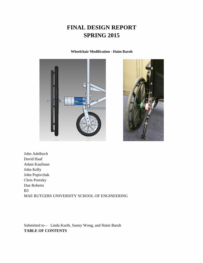
FINAL DESIGN REPORT SPRING 2015 Wheelchair Modification - Haim Baruh John Adelhoch David Haaf Adam Kaufman John Kelly John Popivchak Chris Poresky Dan Roberts B3 MAE RUTGERS UNIVERSITY SCHOOL OF ENGINEERING Submitted to— Linda Kurth, Sunny Wong, and Haim Baruh TABLE OF CONTENTS
-
Upload
adam-kaufman -
Category
Documents
-
view
364 -
download
0
Transcript of Wheelchair Modification Design Report
FINAL DESIGN REPORT
SPRING 2015
Wheelchair Modification - Haim Baruh
John Adelhoch
David Haaf
Adam Kaufman
John Kelly
John Popivchak
Chris Poresky
Dan Roberts
B3
MAE RUTGERS UNIVERSITY SCHOOL OF ENGINEERING
Submitted to— Linda Kurth, Sunny Wong, and Haim Baruh
TABLE OF CONTENTS
1
Contents Page No.
Executive Summary 2
Statement of Problem 2
Design Choice 3
Detailed Design 5
Engineering Analysis 10
Materials 13
Manufacturing Process 14
Manufacturing/Assembly Overview 16
Operation 17
Testing 18
Weaknesses/Unresolved Problems 18
Conclusion 19
References 19
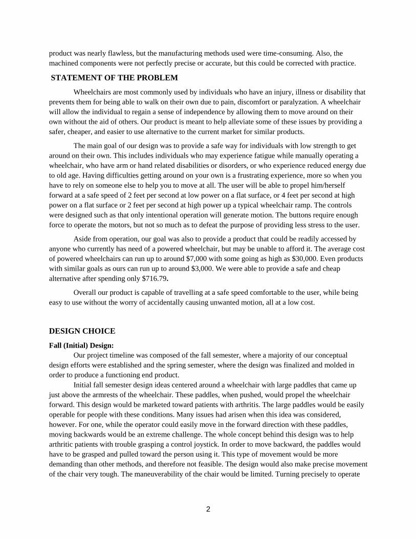
EXECUTIVE SUMMARY
Our team designed and manufactured a kit which attaches to a manual wheelchair frame and
converts it into an electrical one. The kit is composed of a motor and control system which allows the user
to maneuver with minimal physical strength and/or coordination. A budget of $750 was allotted to our
group to select the necessary materials, however we managed to spend a total of $716.79. which included
the components of the motor and control system, the batteries, and various items which connect our
system to the wheelchair. We tested the individual components of our assembly separately (the motor
assembly and the controls assembly) but did not test the interaction of the two before the completion of
this report. Barring significant losses due to a sum of small inaccuracies or unforeseen design flaws in the
final connection, our wheelchair kit should function appropriately on Rutgers Day. The design of our
2
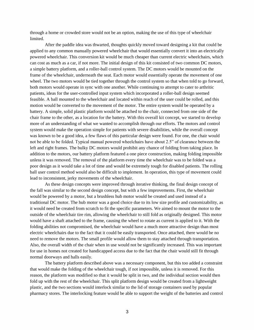
product was nearly flawless, but the manufacturing methods used were time-consuming. Also, the
machined components were not perfectly precise or accurate, but this could be corrected with practice.
STATEMENT OF THE PROBLEM
Wheelchairs are most commonly used by individuals who have an injury, illness or disability that
prevents them for being able to walk on their own due to pain, discomfort or paralyzation. A wheelchair
will allow the individual to regain a sense of independence by allowing them to move around on their
own without the aid of others. Our product is meant to help alleviate some of these issues by providing a
safer, cheaper, and easier to use alternative to the current market for similar products.
The main goal of our design was to provide a safe way for individuals with low strength to get
around on their own. This includes individuals who may experience fatigue while manually operating a
wheelchair, who have arm or hand related disabilities or disorders, or who experience reduced energy due
to old age. Having difficulties getting around on your own is a frustrating experience, more so when you
have to rely on someone else to help you to move at all. The user will be able to propel him/herself
forward at a safe speed of 2 feet per second at low power on a flat surface, or 4 feet per second at high
power on a flat surface or 2 feet per second at high power up a typical wheelchair ramp. The controls
were designed such as that only intentional operation will generate motion. The buttons require enough
force to operate the motors, but not so much as to defeat the purpose of providing less stress to the user.
Aside from operation, our goal was also to provide a product that could be readily accessed by
anyone who currently has need of a powered wheelchair, but may be unable to afford it. The average cost
of powered wheelchairs can run up to around $7,000 with some going as high as $30,000. Even products
with similar goals as ours can run up to around $3,000. We were able to provide a safe and cheap
alternative after spending only $716.79.
Overall our product is capable of travelling at a safe speed comfortable to the user, while being
easy to use without the worry of accidentally causing unwanted motion, all at a low cost.
DESIGN CHOICE
Fall (Initial) Design:
Our project timeline was composed of the fall semester, where a majority of our conceptual
design efforts were established and the spring semester, where the design was finalized and molded in
order to produce a functioning end product.
Initial fall semester design ideas centered around a wheelchair with large paddles that came up
just above the armrests of the wheelchair. These paddles, when pushed, would propel the wheelchair
forward. This design would be marketed toward patients with arthritis. The large paddles would be easily
operable for people with these conditions. Many issues had arisen when this idea was considered,
however. For one, while the operator could easily move in the forward direction with these paddles,
moving backwards would be an extreme challenge. The whole concept behind this design was to help
arthritic patients with trouble grasping a control joystick. In order to move backward, the paddles would
have to be grasped and pulled toward the person using it. This type of movement would be more
demanding than other methods, and therefore not feasible. The design would also make precise movement
of the chair very tough. The maneuverability of the chair would be limited. Turning precisely to operate
3
through a home or crowded store would not be an option, making the use of this type of wheelchair
limited.
After the paddle idea was thwarted, thoughts quickly moved toward designing a kit that could be
applied to any common manually powered wheelchair that would essentially convert it into an electrically
powered wheelchair. This conversion kit would be much cheaper than current electric wheelchairs, which
can cost as much as a car, if not more. The initial design of this kit consisted of two common DC motors,
a simple battery platform, and a roller-ball control system. The DC motors would be mounted on the
frame of the wheelchair, underneath the seat. Each motor would essentially operate the movement of one
wheel. The two motors would be tied together through the control system so that when told to go forward,
both motors would operate in sync with one another. While continuing to attempt to cater to arthritic
patients, ideas for the user-controlled input system which incorporated a roller-ball design seemed
feasible. A ball mounted to the wheelchair and located within reach of the user could be rolled, and this
motion would be converted to the movement of the motor. The entire system would be operated by a
battery. A simple, solid plastic platform would be attached to the chair, connected from one side of the
chair frame to the other, as a location for the battery. With this overall kit concept, we started to develop
more of an understanding of what we wanted to accomplish through our efforts. The motors and control
system would make the operation simple for patients with severe disabilities, while the overall concept
was known to be a good idea, a few flaws of this particular design were found. For one, the chair would
not be able to be folded. Typical manual powered wheelchairs have about 2.5” of clearance between the
left and right frames. The bulky DC motors would prohibit any chance of folding from taking place. In
addition to the motors, our battery platform featured a one piece construction, making folding impossible
unless it was removed. The removal of the platform every time the wheelchair was to be folded was a
poor design as it would take a lot of time and would be extremely tough for disabled patients. The rolling
ball user control method would also be difficult to implement. In operation, this type of movement could
lead to inconsistent, jerky movements of the wheelchair.
As these design concepts were improved through iterative thinking, the final design concept of
the fall was similar to the second design concept, but with a few improvements. First, the wheelchair
would be powered by a motor, but a brushless hub motor would be created and used instead of a
traditional DC motor. The hub motor was a good choice due to its low size profile and customizability, as
it would need be created from scratch to fit the specific parameters. We aimed to mount the motor to the
outside of the wheelchair tire rim, allowing the wheelchair to still fold as originally designed. This motor
would have a shaft attached to the frame, causing the wheel to rotate as current is applied to it. With the
folding abilities not compromised, the wheelchair would have a much more attractive design than most
electric wheelchairs due to the fact that it could be easily transported. Once attached, there would be no
need to remove the motors. The small profile would allow them to stay attached through transportation.
Also, the overall width of the chair when in use would not be significantly increased. This was important
for use in homes not created for handicapped access due to the fact that the chair would still fit through
normal doorways and halls easily.
The battery platform described above was a necessary component, but this too added a constraint
that would make the folding of the wheelchair tough, if not impossible, unless it is removed. For this
reason, the platform was modified so that it would be split in two, and the individual section would then
fold up with the rest of the wheelchair. This split platform design would be created from a lightweight
plastic, and the two sections would interlock similar to the lid of storage containers used by popular
pharmacy stores. The interlocking feature would be able to support the weight of the batteries and control
4
circuitry. With a fixed distance between the frame sections when the wheelchair is completely open, the
precise manufacturing of the two segments would ensure the soundness of the platform under a load.
Should the two piece platform not hold up, supports could be attached from the frame to the individual
platform sections, guaranteeing that the platform would support this weight.
Finally, to conclude our initial fall design concept, the user controlled input for the motors would
be accomplished using large buttons that are often used for gaming controllers. The large size of these
buttons would allow patients with extreme disabilities, such as advanced arthritis, to easily control the
wheelchair. The buttons themselves are also relatively inexpensive. This system was preferred, even
compared to a joystick or trackball, since it required no grasping or significant hand movements. These
controls could easily be operated with just the push of a palm or finger. These buttons would
communicate with and control the motors using an arduino system. An arduino is a microcontroller
prototyping platform that can be used in circuits and programmed to interpret signals from input devices
and send outputs to other devices. The buttons would function as inputs to the arduino, which interpret the
signal from each button as high or low. When depressed, the buttons send a high signal. There would be
five buttons, one to go forward, one to rotate left, one to rotate right, one to go in reverse, and a stop
button. Only one button push could interpreted at a time (with the exception of the stop button which
overrides any other buttons), and pressing multiple buttons simultaneously would produce no effect. The
arduino would take the signals from the buttons, and directs the motor action based on its coding.
Reversing the directions of the motors for the purposes of moving straight in reverse or turning would be
accomplished through the use of an h-bridge, which would be placed in the circuit of the control system
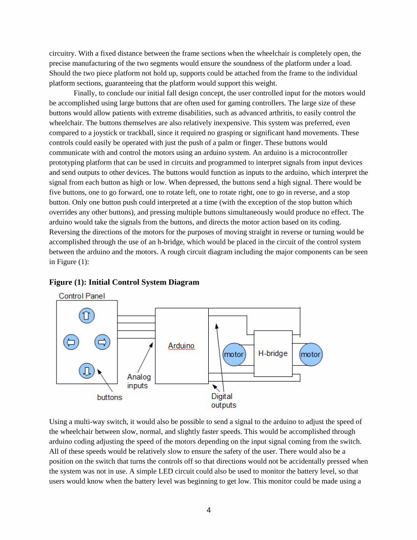
between the arduino and the motors. A rough circuit diagram including the major components can be seen
in Figure (1):
Figure (1): Initial Control System Diagram
Using a multi-way switch, it would also be possible to send a signal to the arduino to adjust the speed of
the wheelchair between slow, normal, and slightly faster speeds. This would be accomplished through
arduino coding adjusting the speed of the motors depending on the input signal coming from the switch.
All of these speeds would be relatively slow to ensure the safety of the user. There would also be a
position on the switch that turns the controls off so that directions would not be accidentally pressed when
the system was not in use. A simple LED circuit could also be used to monitor the battery level, so that
users would know when the battery level was beginning to get low. This monitor could be made using a

5
few LEDs and a zener diode which would respond and would stay lit depending on the voltage level in
the battery. All of these components would be housed within a plastic enclosure that could be mounted
onto either arm of the wheelchair using straps that would go around the arm. The plastic enclosure would
be between one and two inches in thickness so that the control panel would not extrude uncomfortably
outward from the arm.
Spring (Final) Design:
With the design process above finalizing the fall semester, we began fabrication of our product
during winter/early spring. As parts were created and assembly began to take place, various components
of the system needed to be either adjusted or completely redesigned. The efforts during the redesign
stages will be described below:
The entire design and fabrication process was dependent on the parameters of the motor’s stator.
The prefix of stator implies it will remain stationary as the motor operates. The stator purchased for this
project had 12 legs or, slots for the magnet wire to wrap around. It also had a length of 1 ⅜”. The number
of wraps corresponded to different power and torque parameters and was determined through calculations
which are included in the Engineering Analysis section of the report. The stator was then wrapped to
these determined specifications. A larger stator was preferred, but these specialized items were difficult to
purchase. A larger stator would have made the wrapping process easier and less time consuming, but time
constraints and market availability led to the need to purchase the ones that were available. The
parameters of the other project parts were designed with a dependence on the stator’s size and how it was
wrapped.
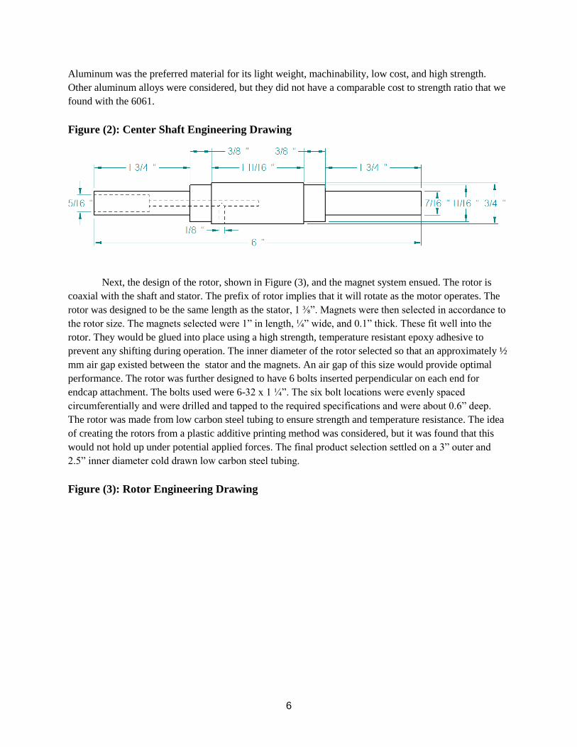
The center shaft of the motor ,shown in Figure (2), was the next part designed. The center shaft
replaced the axle of each wheel, which was previously attached by a simple nut and bolt. The new center
shaft was designed to fit into the wheelchair unit with no modifications needed. The center shaft is
symmetrical from the midpoint. From middle to outer edge, the diameter of the shaft progressively
decreases in diameter across the entire 6” length. The middle section of the center shaft was 1 11/16” long
with a ¾” diameter. This segment attached to the stator. It was passed through the ¾” center of the stator.
The top of the stator was aligned with the outer edge of this cylindrical segment. The stator was affixed to
the shaft by a high strength, temperature resistant epoxy. Since the height of the stator was only 1 ⅜”, the
center shaft had additional length untouched by the stator which allowed a hole to be drilled through
perpendicularly. This hole created an escape pathway for the wires which connected the power supply and
control system to the stator. The diameter of the segment length of the shaft adjacent to the middle section
was called the bearing seat, since it is where the bearings were placed. The diameter of the center shaft at
this section was decreased to 11/16” to match the inner diameter of the bearings. This adjacent section
was milled to a length of ⅜”. The precise fit of the bearing onto the shaft eliminated any unwanted
movement of the bearing during motor operation. The bearing also has limited movement in the axial
direction due to the backstop created by the larger diameter of the center shaft on one side, and by the
endcaps on the other side, which will be discussed further on. The final segment of the shaft, the end
segment, was 1 ¾” long with a 7/16” diameter. These ends were designed to fit through the frame of the
wheelchair on one end and through the bearings of the wheel on the other. The ends of the shaft were
threaded to fit a 5/16-18” bolt. The bolts were fitted with a lock washer to prevent any loosening during
the potentially rough operation of a moving wheelchair. The shaft and stator were therefore designed to
be affixed to the frame of the chair with no rotation. The center shaft was made from alloy 6061 aircraft
aluminum to ensure minimum bending when under the load of the entire system and a passenger.
6
Aluminum was the preferred material for its light weight, machinability, low cost, and high strength.
Other aluminum alloys were considered, but they did not have a comparable cost to strength ratio that we
found with the 6061.
Figure (2): Center Shaft Engineering Drawing
Next, the design of the rotor, shown in Figure (3), and the magnet system ensued. The rotor is
coaxial with the shaft and stator. The prefix of rotor implies that it will rotate as the motor operates. The
rotor was designed to be the same length as the stator, 1 ⅜”. Magnets were then selected in accordance to
the rotor size. The magnets selected were 1” in length, ¼” wide, and 0.1” thick. These fit well into the
rotor. They would be glued into place using a high strength, temperature resistant epoxy adhesive to
prevent any shifting during operation. The inner diameter of the rotor selected so that an approximately ½
mm air gap existed between the stator and the magnets. An air gap of this size would provide optimal
performance. The rotor was further designed to have 6 bolts inserted perpendicular on each end for
endcap attachment. The bolts used were 6-32 x 1 ¼”. The six bolt locations were evenly spaced
circumferentially and were drilled and tapped to the required specifications and were about 0.6” deep.
The rotor was made from low carbon steel tubing to ensure strength and temperature resistance. The idea
of creating the rotors from a plastic additive printing method was considered, but it was found that this
would not hold up under potential applied forces. The final product selection settled on a 3” outer and
2.5” inner diameter cold drawn low carbon steel tubing.
Figure (3): Rotor Engineering Drawing

7
The endcaps, shown in Figure (4) and (5), were the final motor component designed. The endcaps
were of vital importance to the system due to their role in both anchoring the components of the motor
together and by creating a means of transferring power from the spinning rotor to the wheelchair wheels.
The endcaps were also designed to contain the components of the motor, and hence there was an endcap
on either side of the rotor. These two components were very similar except the one adjacent to the
wheelchair wheel had holes for attachment to the wheelchair while the other endcap, more so located
“inside” the wheelchair solely focused on attaching to the rotor. The endcaps were designed with the
same outer diameter as the rotor. This created a smooth transition between the rotor and endcaps to
prevent entanglement of any dangling items as the motor spins. They also had six holes which aligned
with the six bolt holes of the rotor. Bolts passed through the end caps and anchored into the thick steel
rotor, securing the endcaps as tight as possible to the rotor. Maximum strength of the endcaps was
necessary. A recessed divot allowed the bearings to be fully supported around a full 360 degrees of
rotation. Holes centered in the endcap allow for the shaft bolts to pass through the endcap and thread into
the shaft uninhibited. Ventilation spaces were also designed into the endcap to allow heat produced by the
running motor to escape into the atmosphere. Another set of 9 holes were added in the middle of the
endcaps. Bolts passed through these holes to the rim of the wheel. The wheelchair wheel rims had
matching holes drilled into them which corresponded to those of the endcap, which allowed the motor to
be attached to the wheelchair. This attachment ensured the wheel would rotate along with the
endcap/rotor assembly. When power will be applied to the motor, the rotor, endcap, and wheel will all
rotate together as the stator remains stationary. The endcaps were created by an additive printing process
(3d printing) due to the low cost and quick production time. Aluminum endcaps were preferred over the
plastic printed endcaps, but budget constraints limited our options. The aluminum endcaps would also be
much more difficult to manufacture, and time constraints led to the decision to have them printed. The
plastic components were durable and easy to machine for a more precise fit.
Figure (4): Inner Endcap Engineering Drawing

8
Figure (5): Wheel Side Endcap Engineering Drawing
The battery platform was redesigned from the fall semester. Initially, the platform was a two
piece system that would allow the chair to fold when the batteries were removed. After analyzing the 3D
drawings of the proposed system, which were going to be fabricated by an additive printing process, two
issues were found. For one, the pieces were too large to be created by the printing options that were
financially feasible for the project. Secondly, the folding design would not be strong enough to support
the weight of two 25 pound batteries. Due to these findings, the battery platform was then made from an
aluminum block. The aluminum was desirable for its low weight and high strength. The final platform
was 24” wide, 8” long, and ½” thick 6061 aluminum alloy.
For the control system, although many aspects of the final design remained similar to the initial
one, new knowledge gained along the way as well as time and cost constraints required the design to be
changed during construction. The large buttons, which were one of the main points of the system, were
9
still incorporated. However, the main thing that changed was the use of electronic speed controllers
instead of an h-bridge in order to control the speed and direction of the motor’s rotation. It was
determined that an h-bridge would not be able to handle the levels of current and voltage required to drive
the motors. Additionally, the arduino and h-bridge alone cannot precisely or reliably control the speed at
which the motors rotate. Thus, in the final design the arduino drives the motors through the use of two
electronic speed controllers, which take control inputs from the arduinos as well as power from the
batteries to direct the motion of the motors. The speed controllers allow the arduino to control the speed
and direction of the motors based on the frequency of the signal that is sent to them. To make the chair go
forward, both motors are rotated forwards. To make the chair go backward, both motors are rotated
backwards. To make the chair rotate left, the left motor is rotated backward and the right motor is rotated
forward. Lastly, to make the chair rotate right, the left motor is rotated forward and the right motor is
rotated backward. A stop button overrides any other combination of button presses to make both motors
stop. Due to time constraints and the steep learning curve that has been involved in the various electronic
components associated with this project, only one low speed could be used on our prototype.
Additionally, the box containing the control systems is larger than was originally planned in the fall due
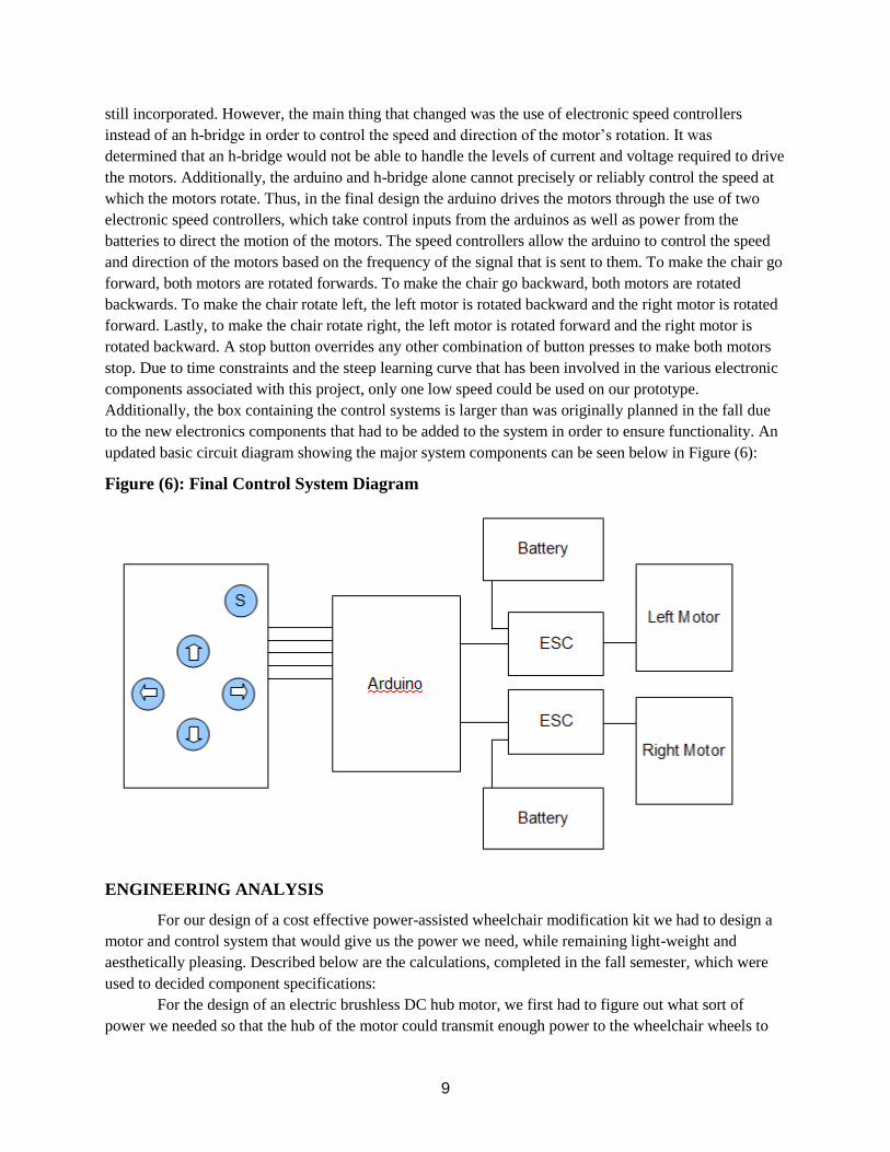
to the new electronics components that had to be added to the system in order to ensure functionality. An
updated basic circuit diagram showing the major system components can be seen below in Figure (6):
Figure (6): Final Control System Diagram
ENGINEERING ANALYSIS
For our design of a cost effective power-assisted wheelchair modification kit we had to design a
motor and control system that would give us the power we need, while remaining light-weight and
aesthetically pleasing. Described below are the calculations, completed in the fall semester, which were
used to decided component specifications:
For the design of an electric brushless DC hub motor, we first had to figure out what sort of
power we needed so that the hub of the motor could transmit enough power to the wheelchair wheels to

10
assist the user. In order to obtain the desired power output we had to figure out the appropriate
components associated with power for a rotating set of wheels. For this we used the following equation
(1):
(1) 𝐻𝐻 = 𝐻∗𝐻𝐻𝐻
5252
Where HP is the power is in units of horsepower, T is torque in foot-pounds, rpm is rotations of the wheel
per minute, and the constant is a conversion factor for rpm and foot-pounds/min to horsepower. For
Torque we used the following equation (2)
(2) 𝐻 = 4𝐻𝐻𝐻0 (𝐻
𝐻+𝐻) 𝐻𝐻
Where m is teeth per phase of the stator, N is complete turns of the wire per phase, B0 is the magnet
surface remanence rating, t is the magnet thickness, g is the air gap width, L is the length of the magnets,
and R is the motor radius.This was the key equation for determining the quality of the motor needed to
suit our needs.
Starting with the easiest portion of this equation (1) we wanted to find how many revolutions of
the wheel we desired per minute, and for that we needed to know how fast we wanted our power-assisted
wheelchair to travel when activated. Keeping in mind that our project was being designed for those with
special needs in situations where safety is our first priority, we decided to go with a speed of around 2
feet/second. In order to convert this to rpms we used the following equation (3):
(3) 𝐻𝐻𝐻 = 120𝐻𝐻
𝐻
Where 120π is a conversion factor for the full rotation of a circular object times the number of seconds in
a minute, 𝑉 is our desired speed in feet/second and r is the radius of the wheel on our wheelchair in feet.
For our project we had a wheelchair with one foot radius wheels. For wheelchairs with other
wheel sizes the power of the motor would be slightly different and may require some modification. Since
the overall power equation is factored in by 1/radius, a smaller wheel radius would require a higher power
if the torque remained the same, while a larger wheel radius would have a lower power requirement.
However, a smaller person would typically use a smaller wheelchair which would have a smaller wheel
radius. A smaller body would mean less weight which would result in a lower torque requirement which
would lower the power requirement. In our calculation of required torque we used data collected in a
previous study of required torque of wheelchair users over different surfaces. The table below shows the
average values of required torque per wheel for a person weighing between 150 and 200 lbs on varying
surfaces in Table (1):
Table (1): Required Torque for Different Surfaces
Torque (ft-lbs): 1.475 ± 0.738 1.9177 ± 0.885 2.2864 ± 1.18 2.5815 ± 1.03
Surface Type: wood, tile, carpet,
smooth concrete
(reference surface)
interlocking
(uneven) concrete
pavers
grass, dirt 5 degree concrete
ramp
The reference surface was smooth concrete and required an average torque of about 1.5 foot-
pounds. Wood, tile and carpet all produced similar torque requirements. While traveling over interlocking
concrete pavers of non-uniform height the required average torque became about 1.9 foot-pounds. Dirt
11
and grass are even more random in height and friction and so the required average torque became about
2.3 foot-pounds. As expected, the highest torque requirement is found when an opposing force is applied
with a ramp that has a 5 degree slope. The average required torque is about 2.6 with as high as 3.6 foot-
pounds.
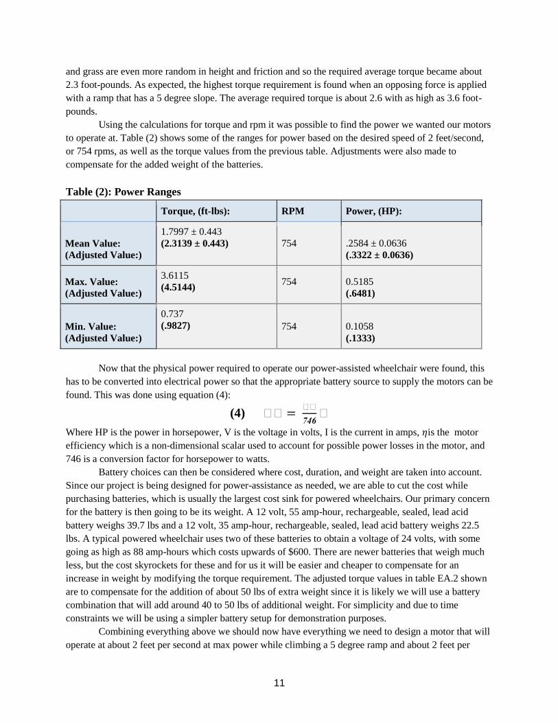
Using the calculations for torque and rpm it was possible to find the power we wanted our motors
to operate at. Table (2) shows some of the ranges for power based on the desired speed of 2 feet/second,
or 754 rpms, as well as the torque values from the previous table. Adjustments were also made to
compensate for the added weight of the batteries.
Table (2): Power Ranges
Torque, (ft-lbs): RPM Power, (HP):
Mean Value: (Adjusted Value:)
1.7997 ± 0.443 (2.3139 ± 0.443) 754
.2584 ± 0.0636 (.3322 ± 0.0636)
Max. Value: (Adjusted Value:)
3.6115 (4.5144)
754
0.5185 (.6481)
Min. Value: (Adjusted Value:)
0.737 (.9827) 754
0.1058
(.1333)
Now that the physical power required to operate our power-assisted wheelchair were found, this
has to be converted into electrical power so that the appropriate battery source to supply the motors can be
found. This was done using equation (4):
(4) 𝐻𝐻 = 𝐻𝐻
746𝐻
Where HP is the power in horsepower, V is the voltage in volts, I is the current in amps, 𝜂is the motor
efficiency which is a non-dimensional scalar used to account for possible power losses in the motor, and
746 is a conversion factor for horsepower to watts.
Battery choices can then be considered where cost, duration, and weight are taken into account.
Since our project is being designed for power-assistance as needed, we are able to cut the cost while
purchasing batteries, which is usually the largest cost sink for powered wheelchairs. Our primary concern
for the battery is then going to be its weight. A 12 volt, 55 amp-hour, rechargeable, sealed, lead acid
battery weighs 39.7 lbs and a 12 volt, 35 amp-hour, rechargeable, sealed, lead acid battery weighs 22.5
lbs. A typical powered wheelchair uses two of these batteries to obtain a voltage of 24 volts, with some
going as high as 88 amp-hours which costs upwards of $600. There are newer batteries that weigh much
less, but the cost skyrockets for these and for us it will be easier and cheaper to compensate for an
increase in weight by modifying the torque requirement. The adjusted torque values in table EA.2 shown
are to compensate for the addition of about 50 lbs of extra weight since it is likely we will use a battery
combination that will add around 40 to 50 lbs of additional weight. For simplicity and due to time
constraints we will be using a simpler battery setup for demonstration purposes.
Combining everything above we should now have everything we need to design a motor that will
operate at about 2 feet per second at max power while climbing a 5 degree ramp and about 2 feet per
12
second at low power, or about 4 feet per second at max power, on most typical surfaces for a person
weighing between 150 and 200 pounds.
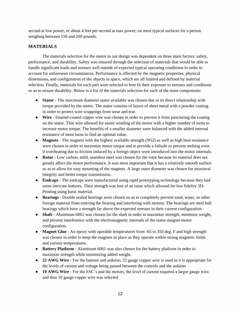
MATERIALS
The materials selection for the motor in our design was dependent on three main factors: safety,
performance, and durability. Safety was ensured through the selection of materials that would be able to
handle significant loads and stresses well outside of expected typical operating conditions in order to
account for unforeseen circumstances. Performance is affected by the magnetic properties, physical
dimensions, and configuration of the objects in space, which are all limited and defined by material
selection. Finally, materials for each part were selected to best fit their exposure to stresses and conditions
so as to ensure durability. Below is a list of the materials selection for each of the main components:
● Stator - The maximum diameter stator available was chosen due to its direct relationship with
torque provided by the motor. The stator consists of layers of sheet metal with a powder coating
in order to protect wire wrappings from wear and tear.
● Wire - Enamel-coated copper wire was chosen in order to prevent it from puncturing the coating
on the stator. Thin wire allowed for easier winding of the motor with a higher number of turns to
increase motor torque. The benefits of a smaller diameter were balanced with the added internal
resistance of more turns to find an optimal value.
● Magnets - The magnets with the highest available strength (N52) as well as high heat resistance
were chosen in order to maximize motor torque and to provide a failsafe to prevent melting even
if overheating due to friction induced by a foreign object were introduced into the motor internals.
● Rotor - Low carbon, mild, seamless steel was chosen for the rotor because its material does not
greatly affect the motor performance. It was most important that it has a relatively smooth surface
so as to allow for easy mounting of the magnets. A large outer diameter was chosen for structural
integrity and better torque transmission.
● Endcaps - The endcaps were manufactured using rapid prototyping technology because they had
some intricate features. Their strength was less of an issue which allowed for low fidelity 3D-
Printing using basic material.
● Bearings - Double sealed bearings were chosen so as to completely prevent sand, water, or other
foreign material from entering the bearing and interfering with motion. The bearings are steel ball
bearings which have a strength far above the expected stresses in their current configuration.
● Shaft - Aluminum 6061 was chosen for the shaft in order to maximize strength, minimize weight,
and prevent interference with the electromagnetic internals of the stator-magnet-motor
configuration.
● Magnet Glue - An epoxy with operable temperatures from -65 to 350 deg. F and high strength
was chosen in order to keep the magnets in place as they operate within strong magnetic fields
and various temperatures.
● Battery Platform - Aluminum 6061 was also chosen for the battery platform in order to
maximize strength while minimizing added weight.
● 22 AWG Wire - For the buttons and arduino, 22 gauge copper wire is used as it is appropriate for
the levels of current and voltage being passed between the controls and the arduino
● 10 AWG Wire - For the ESC’s and the motors, the level of current required a larger gauge wire,
and thus 10 gauge copper wire was selected
13
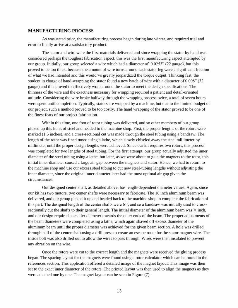
MANUFACTURING PROCESS
As was stated prior, the manufacturing process began during late winter, and required trial and
error to finally arrive at a satisfactory product.
The stator and wire were the first materials delivered and since wrapping the stator by hand was
considered perhaps the toughest fabrication aspect, this was the first manufacturing aspect attempted by
our group. Initially, our group selected a wire which had a diameter of 0.0253” (22 gauge), but this
proved to be too thick, because the amount of wire turns around each stator leg were a significant fraction
of what we had intended and this would’ve greatly jeopardized the torque output. Thinking fast, the
student in charge of hand-wrapping the stator found a new batch of wire with a diameter of 0.008” (32
gauge) and this proved to effectively wrap around the stator to meet the design specifications. The
thinness of the wire and the exactness necessary for wrapping required a patient and detail-oriented
attitude. Considering the wire broke halfway through the wrapping process twice, a total of seven hours
were spent until completion. Typically, stators are wrapped by a machine, but due to the limited budget of
our project, such a method proved to be too costly. The hand wrapping of the stator proved to be one of
the finest feats of our project fabrication.
Within this time, one foot of rotor tubing was delivered, and so other members of our group
picked up this hunk of steel and headed to the machine shop. First, the proper lengths of the rotors were
marked (1.5 inches), and a cross-sectional cut was made through the steel tubing using a bandsaw. The
length of the rotor was fined tuned using a lathe, which slowly chiseled away the steel millimeter by
millimeter until the proper design lengths were achieved. Since our kit requires two rotors, this process
was completed for two lengths of steel tubing. For the first attempt, our group actually adjusted the inner
diameter of the steel tubing using a lathe, but later, as we were about to glue the magnets to the rotor, this
initial inner diameter caused a large air-gap between the magnets and stator. Hence, we had to return to
the machine shop and use our excess steel tubing to cut new steel-tubing lengths without adjusting the
inner diameter, since the original inner diameter later had the most optimal air gap given the
circumstances.
Our designed center shaft, as detailed above, has length-dependent diameter values. Again, since
our kit has two motors, two center shafts were necessary to fabricate. The 18 inch aluminum beam was
delivered, and our group picked it up and headed back to the machine shop to complete the fabrication of
this part. The designed length of the center shafts were 6’’, and so a bandsaw was initially used to cross-
sectionally cut the shafts to their general length. The initial diameter of the aluminum beam was ¾ inch,
and our design required a smaller diameter towards the outer ends of the beam. The proper adjustments of
the beam diameters were completed using a lathe, which again shaved off excess diameter of the
aluminum beam until the proper diameter was achieved for the given beam section. A hole was drilled
through half of the center shaft using a drill press to create an escape route for the stator magnet wire. The
inside bolt was also drilled out to allow the wires to pass through. Wires were then insulated to prevent
any abrasion on the wire.
Once the rotors were cut to the correct length and the magnets were received the gluing process
began. The spacing layout for the magnets were found using a rotor calculator which can be found in the
references section. This application offered a detailed image of the magnet layout. This image was then
set to the exact inner diameter of the rotors. The printed layout was then used to align the magnets as they
were attached one by one. The magnet layout can be seen in Figure (7):

14
Figure (7): Magnet/Rotor Layout
As the magnets were attached, a 72-hour high strength epoxy was applied. The same epoxy was later used
to glue the stator to the center shaft for each of the motors. The stator was clamped down and one side
was sealed with tape. The mid section of the center shaft was designed with a diameter about 2 mm less
than the stator so that a 1 mm gap existed between the surface of the stator and center shaft. This left
room for the epoxy to fit while gluing. The center shaft and inside of the stator were then coated with the
epoxy. Finally the center shaft was inserted into the stator and the excess epoxy was removed.
The endcaps were designed using a 3D drawing software, Solid Edge, and the completed designs
were saved as a .stl file onto an SD card. This SD card was then taken to Rutgers Makerspace, which is a
free additive printing (3D printing) service ran by Rutgers students. The process was relatively simple as
one of our group members handed the SD card to a Makerspace volunteer and showed which .stl files
needed printing. There were four parts total which were manufactured since one endcap is composed of
two parts that are screwed into both sides of the rotor. Since there are two rotors, two endcaps were
needed and hence four parts total were printed. The manufacturing of the first part ran smoothly, but the
machine broke after this and delayed the printing of the other parts. The final endcap products were
accurate and attached by bolt into the rotors with ease.
The manufacturing of the control system took place gradually over a few weeks. It was a learning
process, as our group had never really worked with electronics for a project of this level of complexity
before. It was through construction and experimentation that we gradually learned of the various
components and procedures necessary to construct our circuit. Wiring the components in the circuit was
difficult at first, but gradually became easier with practice.
MANUFACTURING/ASSEMBLY OVERVIEW
The assembly of all of the motor components is straightforward and can be completed with
simple hand tools. An exploded view of the motor is shown in Figure (8):
Figure (8): Exploded views of Motor Assembly

15
As you have read, our product is very convenient for the user because it requires minimal
mechanical knowledge and only simple hand tools in order to install at home. The shaft of the mechanical
wheelchair is simply removed by unscrewing the bolts on either end. Our product is then inserted where
the old shaft once was and the included bolts are used to screw into the shaft. Holes were drilled through
the rim of the wheelchair wheel, the only modification to the wheelchair necessary. From there, the wires
need only to be inserted into their respective connections as will be shown in the instruction manual.
This simplicity on the end-user side is achieved through careful and precise manufacturing and
assembly of the parts prior to their packaging and shipping for delivery to the customer. There are three
main groups of techniques employed to completely construct the manual-to-electric wheelchair
conversion kit:
1. The metal pieces including the shafts, rotors, and battery platform are machined.
2. The endcaps are 3D-Printed using rapid prototyping machines.
3. The stator winding, circuitry, and connections are constructed by hand (and later, using precise
machines) in order to ensure accuracy.
The endcaps are unique in that they have depressions designed as features which allow the motor
internals to fit into them snugly. The shafts have varying diameters so as to accommodate the pieces that
fit onto each section and to prevent them from moving axially along the rod. Finally, the shafts were
designed to fit perfectly into the existing standardized American wheelchair structure to optimize
compatibility and versatility of our product.

16
OPERATION
Our product offers a very simple control system that requires very little movement. This is a
result of our solution to the original problem; to provide a safer, cheaper and easier alternative to the
current market for similar products. One would operate the wheelchair using the four button control
system that is easily connectable to either wheelchair armrest. This allows the user to gently rest their arm
down and use only one or two fingers to move. The up arrow moves the chair forward, while the down
arrow moves it in reverse. When the user hits left or right on the buttons, only one wheel motor is
activated which turns the chair in the respective direction. If the user would like the wheelchair to be
folded for easy transportation or storage, the batteries and battery platform could be removed, and the
wheelchair will fold according to its original design.
As stated before, the design of our product was intended for users confined to a wheelchair with
limited mobility. Our product is targeted to help those who do not have enough strength or mobility to
push the wheelchair on their own. The specific targeted users for our product are patients with arthritis,
scoliosis, or other mobility limiting diseases, as well as the elderly who simply do not have the strength to
operate manual wheelchair. Ideally, our product would be sold to hospitals, or assisted living
communities; along with individual clients.
Some constraints that we may run into when trying to market this product is a size constraint. The
addition of the motors to each wheel makes the wheelchair about 3.5 inches wider overall. This can make
the chair difficult to maneuver through doorways and hallways if those passages are too narrow. Another
size constraint that we would experience selling our product is that not every manual wheelchair is the
exact same size, or has a frame that would match the connections designed for our product. When
designing we tried to choose a wheelchair that best represents the norm, however, some adjustments may
have to be made to the wheelchair kit depending on the client. A third and final size constraint that our
product may experience is a user weight limit. Our original designs were intended for patients over 200
pounds. Due to size limitations when purchasing the stators, the maximum weight the wheelchair can
operate with is 130-150 pounds. This causes problems when a heavier client wants our product. A heavier
client would cause the need of a larger stator therefore, larger motors. This may interfere with the
wheelchairs ability to enter doorways even more than the current design.
Other constraints that would limit the success of our product are geological and environmental
constraints. A client that lives in a very mountainous region may have difficulty operating our product. A
steep incline required more torque from the motors, in combination with a heavier user can cause the
product to fail. Steep hilly areas can also be a safety hazard if the wheelchair gains too much speed. In
addition, a user that lives in a very wet and rainy region may also experience problems. Slippery
conditions can create a safety issue with the wheelchair sliding.
TESTING
Our testing procedure for the control system involved an investigation into the proper frequency
inputs requisite to produce the desired current and torque. We also needed to ensure that the buttons,
when pressed, would produce the intended effect.
Simultaneously, we tested the mechanical interactions taking place inside the motor assembly.
We made sure that the rotational motion proceeded smoothly and had different group members watch
17
different components during operation in order to quickly spot and resolve any unwanted contact or
interference.
At the time of writing this report, the entire wheelchair assembly with the control system and
motor functioning together has not been tested in a practical situation where the wheelchair would move.
Because the control system and motor work individually, however, we are confident that the system will
be ready for demonstration on Rutgers Day.
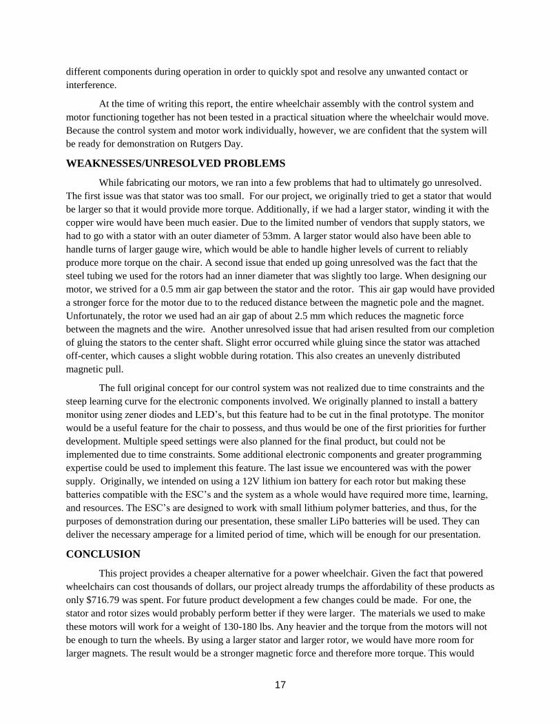
WEAKNESSES/UNRESOLVED PROBLEMS
While fabricating our motors, we ran into a few problems that had to ultimately go unresolved.
The first issue was that stator was too small. For our project, we originally tried to get a stator that would
be larger so that it would provide more torque. Additionally, if we had a larger stator, winding it with the
copper wire would have been much easier. Due to the limited number of vendors that supply stators, we
had to go with a stator with an outer diameter of 53mm. A larger stator would also have been able to
handle turns of larger gauge wire, which would be able to handle higher levels of current to reliably
produce more torque on the chair. A second issue that ended up going unresolved was the fact that the
steel tubing we used for the rotors had an inner diameter that was slightly too large. When designing our
motor, we strived for a 0.5 mm air gap between the stator and the rotor. This air gap would have provided
a stronger force for the motor due to to the reduced distance between the magnetic pole and the magnet.
Unfortunately, the rotor we used had an air gap of about 2.5 mm which reduces the magnetic force
between the magnets and the wire. Another unresolved issue that had arisen resulted from our completion
of gluing the stators to the center shaft. Slight error occurred while gluing since the stator was attached
off-center, which causes a slight wobble during rotation. This also creates an unevenly distributed
magnetic pull.
The full original concept for our control system was not realized due to time constraints and the
steep learning curve for the electronic components involved. We originally planned to install a battery
monitor using zener diodes and LED’s, but this feature had to be cut in the final prototype. The monitor
would be a useful feature for the chair to possess, and thus would be one of the first priorities for further
development. Multiple speed settings were also planned for the final product, but could not be
implemented due to time constraints. Some additional electronic components and greater programming
expertise could be used to implement this feature. The last issue we encountered was with the power
supply. Originally, we intended on using a 12V lithium ion battery for each rotor but making these
batteries compatible with the ESC’s and the system as a whole would have required more time, learning,
and resources. The ESC’s are designed to work with small lithium polymer batteries, and thus, for the
purposes of demonstration during our presentation, these smaller LiPo batteries will be used. They can
deliver the necessary amperage for a limited period of time, which will be enough for our presentation.
CONCLUSION
This project provides a cheaper alternative for a power wheelchair. Given the fact that powered
wheelchairs can cost thousands of dollars, our project already trumps the affordability of these products as
only $716.79 was spent. For future product development a few changes could be made. For one, the
stator and rotor sizes would probably perform better if they were larger. The materials we used to make
these motors will work for a weight of 130-180 lbs. Any heavier and the torque from the motors will not
be enough to turn the wheels. By using a larger stator and larger rotor, we would have more room for
larger magnets. The result would be a stronger magnetic force and therefore more torque. This would

18
however require more power to drive the motor. Now knowing the amounts of materials needed for
construction, we could be more efficient with budget to delegate for other use (motor materials, higher-
quality electronics components). The only part that would be troublesome to duplicate would be the
wrapped stators. This could be done by a machine but for the purpose of our project we did it manually. If
this were to be made available for commercial use, a stator wrapping machine would be necessary.
REFERENCES
● http://www.instructables.com/idReferences:/Make-Your-Own-Miniature-Electric-Hub-Motor/
● http://www.instructables.com/id/ESC-Programming-on-Arduino-Hobbyking-ESC/
● https://dronesandrovs.wordpress.com/2012/11/24/how-to-control-a-brushless-motor-esc-with-
arduino/
● Koontz, A. (2005). A kinetic analysis of manual wheelchair propulsion during start-up on select
indoor and outdoor surfaces. Journal of Rehabilitation Research and Development,42(4), 447-
458.
● http://www.gobrushless.com/shop/index.php?app=ccp0&ns=display&ref=rotorcalc&Stator_dia=
53&Rotor_dia=63.5&Mag_width=6.35&Mag_thick=2.54&num_holes=0&FS_airgap=4.2891&di
m_holes=0&num_poles=14&submit=Calculate+Now