Wheel Set - Shimanosi.shimano.com/pdfs/dm/DM-WH0004-01-ENG.pdf · < wh-m785-f / wh-m788-r /...
31
(English) DM-WH0004-01 Dealer's Manual Wheel Set ROAD WH-6700 WH-RS80-C50 WH-RS80-A-C24 WH-RS30-A WH-RS10-A WH-R501-30 WH-R501 MTB WH-M785-F WH-M785-R WH-M788-R WH-M785-F15 WH-M788-F15 SM-RIMTAPE
Transcript of Wheel Set - Shimanosi.shimano.com/pdfs/dm/DM-WH0004-01-ENG.pdf · < wh-m785-f / wh-m788-r /...
(English) DM-WH0004-01
Dealer's Manual
Wheel Set
ROADWH-6700
WH-RS80-C50WH-RS80-A-C24
WH-RS30-AWH-RS10-A
WH-R501-30WH-R501
MTBWH-M785-FWH-M785-RWH-M788-R
WH-M785-F15WH-M788-F15
SM-RIMTAPE
2
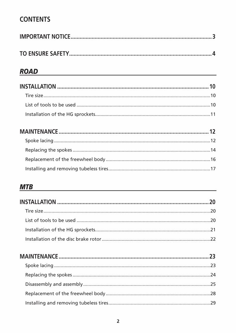
CONTENTS
IMPORTANT NOTICE .............................................................................................. 3
TO ENSURE SAFETY ............................................................................................... 4
ROAD
INSTALLATION ..................................................................................................... 10Tire size ..............................................................................................................................10
List of tools to be used .....................................................................................................10
Installation of the HG sprockets.......................................................................................11
MAINTENANCE .................................................................................................... 12Spoke lacing ......................................................................................................................12
Replacing the spokes ........................................................................................................14
Replacement of the freewheel body ...............................................................................16
Installing and removing tubeless tires .............................................................................17
MTB
INSTALLATION ..................................................................................................... 20Tire size ..............................................................................................................................20
List of tools to be used .....................................................................................................20
Installation of the HG sprockets.......................................................................................21
Installation of the disc brake rotor ..................................................................................22
MAINTENANCE .................................................................................................... 23Spoke lacing ......................................................................................................................23
Replacing the spokes ........................................................................................................24
Disassembly and assembly ................................................................................................25
Replacement of the freewheel body ...............................................................................28
Installing and removing tubeless tires .............................................................................29
3
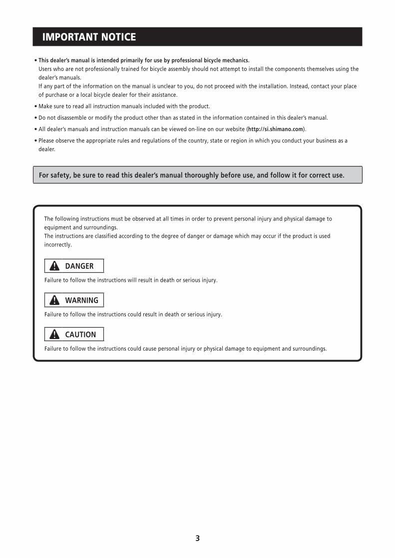
IMPORTANT NOTICE
• This dealer’s manual is intended primarily for use by professional bicycle mechanics.Users who are not professionally trained for bicycle assembly should not attempt to install the components themselves using the dealer’s manuals.If any part of the information on the manual is unclear to you, do not proceed with the installation. Instead, contact your place of purchase or a local bicycle dealer for their assistance.
• Make sure to read all instruction manuals included with the product.
• Do not disassemble or modify the product other than as stated in the information contained in this dealer’s manual.
• All dealer’s manuals and instruction manuals can be viewed on-line on our website (http://si.shimano.com).
• Please observe the appropriate rules and regulations of the country, state or region in which you conduct your business as a dealer.
For safety, be sure to read this dealer’s manual thoroughly before use, and follow it for correct use.
The following instructions must be observed at all times in order to prevent personal injury and physical damage to equipment and surroundings.The instructions are classified according to the degree of danger or damage which may occur if the product is used incorrectly.
DANGER
Failure to follow the instructions will result in death or serious injury.
WARNING
Failure to follow the instructions could result in death or serious injury.
CAUTION
Failure to follow the instructions could cause personal injury or physical damage to equipment and surroundings.

4
TO ENSURE SAFETY
WARNING
• When installing components, be sure to follow the instructions that are given in the instruction manuals.It is recommended that you use only genuine Shimano parts. If parts such as bolts and nuts become loose or damaged, the bicycle may suddenly fall over, which may cause serious injury. In addition, if adjustments are not carried out correctly, problems may occur, and the bicycle may suddenly fall over, which may cause serious injury.
• Be sure to wear safety glasses or goggles to protect your eyes while performing maintenance tasks such as replacing parts.
• After reading the dealer's manual thoroughly, keep it in a safe place for later reference.
Be sure to also inform users of the following:
�Common descriptions regarding ROAD wheel / MTB wheel • Check that the wheels are fastened securely before riding the bicycle. If the wheels are loose in any way, they may come off the bicycle and serious injury may result.
• If the quick release mechanism is not used correctly, the wheel may come off the bicycle and serious injury could result. Read the Service Instructions for the quick release mechanism thoroughly before use.
• Before use, check the wheels to make sure that there are no bent or loose spokes, dents, scratches or cracks on the rim surface. Do not use the wheel if any of these problems are found.
�Descriptions regarding ROAD wheel • These wheels are designed for riding on paved surfaces. If the wheels are used on unpaved surfaces, the wheels may become bent or damaged, and accidents may result.
• The hollow on the opposite side to the valve hole is an indicator for the amount of rim wear. If this hollow can no longer be seen, stop using the rim. If you continue using the rim, it may break, and the bicycle may fall over and an accident may result.
�Descriptions regarding MTB wheel • The disc brake calipers and disc brake rotor will become hot when the brakes are operated, so do not touch them while riding or immediately after dismounting from the bicycle, otherwise you may get burned. Check that the brake components have cooled down sufficiently before attempting to adjust the brakes.
• Be sure to carefully read the Service Instructions for the disc brakes also.
< WH-M785-F / WH-M788-R / WH-M785-R >
• If the quick release lever is on the same side as the disc brake rotor, there is the danger that it may interfere with the disc brake rotor. Make sure that even if the quick release lever is tightened with your palm with all your strength, the quick release lever does not interfere with the disc brake rotor. If the lever interferes with the disc brake rotor, stop using the wheel and consult a dealer or an agency.
Quick release lever
Disc brake rotor
5
< WH-M785-F >
• The wheel is designed for cross-country riding. Do not use it for downhill riding, otherwise the wheel may become bent or otherwise damaged, and accidents may occur as a result.
< WH-M788-F15 / WH-M785-F15 >
• WH-M788-F15 is designed for trail riding, and WH-M785-F15 is designed for cross-country riding. Do not use either wheel for downhill riding and free ride, otherwise the wheel may become bent or otherwise damaged, and accidents may occur as a result.
• The WH-M788-F15 / WH-M785-F15 is not designed for downhill bicycle riding and freeriding. However, depending on the riding condition, the hub axle could develop a crack, which may result in failure of the hub axle. This can lead to an accident that could result in serious injury or even death. Before riding, you should carefully check your hubs to make sure that there are no cracks in the axles, and if you find any sign of a crack or any other unusual condition, do NOT use the bicycle.
• The WH-M788-F15 / WH-M785-F15 can be used in combination with a special front fork and the E-Thru. If it is used in combination with any other front fork or fixed axle, it may cause the wheel to become detached from the bicycle while you are riding and result in serious bodily injury.
• The securing method and tightening torque for the front wheel both vary depending on the type of front suspension fork being used. When installing the front wheel to the front suspension fork, always be sure to follow the directions given in the Service Instructions for the front suspension fork. If the directions are not followed, the front wheel may fall out of the front suspension fork and serious injury may result.
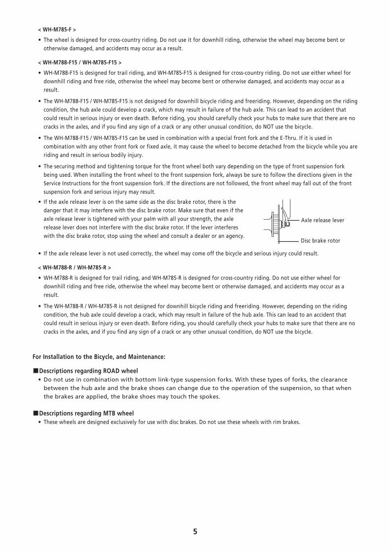
• If the axle release lever is on the same side as the disc brake rotor, there is the danger that it may interfere with the disc brake rotor. Make sure that even if the axle release lever is tightened with your palm with all your strength, the axle release lever does not interfere with the disc brake rotor. If the lever interferes with the disc brake rotor, stop using the wheel and consult a dealer or an agency.
Axle release lever
Disc brake rotor
• If the axle release lever is not used correctly, the wheel may come off the bicycle and serious injury could result.
< WH-M788-R / WH-M785-R >
• WH-M788-R is designed for trail riding, and WH-M785-R is designed for cross-country riding. Do not use either wheel for downhill riding and free ride, otherwise the wheel may become bent or otherwise damaged, and accidents may occur as a result.
• The WH-M788-R / WH-M785-R is not designed for downhill bicycle riding and freeriding. However, depending on the riding condition, the hub axle could develop a crack, which may result in failure of the hub axle. This can lead to an accident that could result in serious injury or even death. Before riding, you should carefully check your hubs to make sure that there are no cracks in the axles, and if you find any sign of a crack or any other unusual condition, do NOT use the bicycle.
For Installation to the Bicycle, and Maintenance:
�Descriptions regarding ROAD wheel • Do not use in combination with bottom link-type suspension forks. With these types of forks, the clearance between the hub axle and the brake shoes can change due to the operation of the suspension, so that when the brakes are applied, the brake shoes may touch the spokes.
�Descriptions regarding MTB wheel • These wheels are designed exclusively for use with disc brakes. Do not use these wheels with rim brakes.
6
CAUTION
Be sure to also inform users of the following:
�Common descriptions regarding ROAD wheel / MTB wheel • The tires should be inflated to the pressure indicated on the tires before use.
�Descriptions regarding ROAD wheel
< WH-6700 >
• Do not use rim tape. Rim tape may make it difficult to remove and install the tire, and the tire or tube may become damaged or the tires may suddenly puncture and come off, and severe injury may result.
< WH-RS80-C50 / WH-RS80-A-C24 / WH-R501-30 / WH-R501 / WH-RS30-A / WH-RS10-A >
• Use rim tape which can withstand high pressures, otherwise the tires may suddenly puncture and come off, and severe injury may result. Furthermore, it is not recommended that you reuse rim tape after they have been removed from the wheel. If the tape or plugs are reused, the tires may suddenly puncture and come off, and severe injury may result.
• When you replace the rim tape, use the one that matches the rim size. If you use a rim tape that does not match the rim size, a sudden puncture may occur, and you may fall off the bicycle.
�Descriptions regarding MTB wheel • Do not use rim tape. Rim tape may make it difficult to remove and install the tire, and the tire or tube may become damaged or the tires may suddenly puncture and come off, and severe injury may result.
• Be careful not to overtighten the plugs when adjusting the spoke tensions. If the plugs are overtightened, damage to the rim may result.
• When you use a puncture repair agent, you should consult a dealer or an agency.
Burn-in period
• Disc brakes have a burn-in period, and the braking force will gradually increase as the burn-in period progresses. Make sure that you are aware of any such increases in braking force when using the brakes during the burn-in period. The same thing will happen when the brake pads or disc brake rotor are replaced.
For Installation to the Bicycle, and Maintenance:
�Descriptions regarding MTB wheel • When using the special tool (TL-FC36) to remove and install the rotor mounting ring, be careful not to touch the outside of the disc brake rotor with your hands. Wear gloves to protect your hands from getting cut.
7
NOTE
Be sure to also inform users of the following:
�Common descriptions regarding ROAD wheel / MTB wheel • Do not apply any oil to the inside of the hub, otherwise the grease will come out.
• We recommend that you ask bicycle dealers to adjust the spoke tensions if there is any initial play in the spokes and after the first 1,000 km of riding.
• Special spoke wrenches are available as optional accessories.
• Products are not guaranteed against natural wear and deterioration from normal use and aging.
• For maximum performance we highly recommend Shimano lubricants and maintenance products.
�Descriptions regarding ROAD wheel • Before use, check that there are no pieces of metal or other foreign objects sticking to the brake pads. If any such items are present, they may cause damage to the rim when the brakes are applied.
• The Shimano R55HC (high performance) brake shoes use an aggressive compound designed with an emphasis on maximum performance in wet conditions, however they will cause accelerated rim wear. Shimano accepts no responsibility for reduced rim life which might occur from using R55HC brake shoes.
< WH-6700 >
• We do not recommend that you use general-purpose alkaline puncture repair agents, as they may cause the rims to corrode and allow air leaks to occur.
�Descriptions regarding MTB wheel
• Do not use detergents or chemical cleaners to wipe the wheel, otherwise they may cause the air sealant that has been applied to the joints in the rim to peel off.
• Do not use detergent or other chemicals when wiping the wheel, otherwise it may cause the sticker on the rim to peel off.
• We do not recommend that you use general-purpose alkaline puncture repair agents, as they may cause the rims to corrode and allow air leaks to occur.
8
For Installation to the Bicycle, and Maintenance:
�Common descriptions regarding ROAD wheel / MTB wheel
• If the wheel becomes stiff and difficult to turn, you should lubricate it with grease.
• For compatible reflectors and spoke protectors, check the specifications table (http://www.si.shimano.com).
�Descriptions regarding ROAD wheel • Use of genuine Shimano spokes and nipples is strongly recommended. If genuine Shimano parts are not used, the hubs or rims may become damaged.
• The nipples have large diameters and are easy to rotate in order to make it easier to increase the spoke tension. However, be careful not to overtighten the nipples when adjusting the spoke tensions. If the nipples are overtightened, damage to the rim may result. (We recommended that you ask authorized bicycle dealers to make the adjustments.)
< WH-6700 >
• Use the rim-side plug to carry out truing and spoke tension adjustment for the WH-6700.
• Use of genuine Shimano spokes and nipples is strongly recommended. If non-Shimano parts are used, the area where the spokes fit into the hub unit may become damaged.
• The plugs have large diameters and are easy to rotate in order to make it easier to increase the spoke tension. However, be careful not to overtighten the plugs when adjusting the spoke tensions. If the plugs are overtightened, damage to the rim may result. (We recommended that you ask authorized bicycle dealers to make the adjustments.)
�Descriptions regarding MTB wheel • Use genuine Shimano spokes, nuts, plugs and washers, otherwise damage to the rim and hub unit may result.
The actual product may differ from the illustration because this manual is intended chiefly to explain the procedures for using the product.

ROAD
10
INSTALLATION
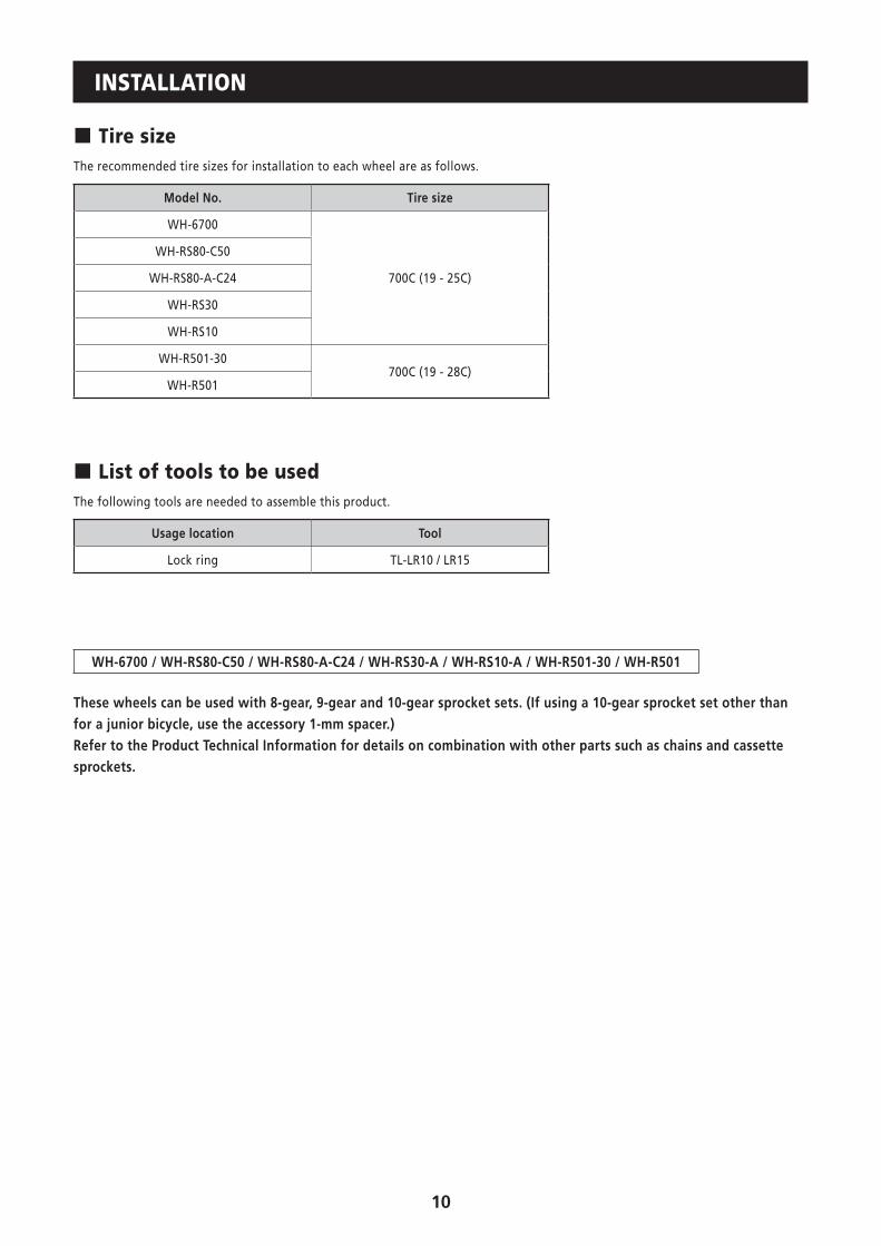
� Tire sizeThe recommended tire sizes for installation to each wheel are as follows.
Model No. Tire size
WH-6700
700C (19 - 25C)
WH-RS80-C50
WH-RS80-A-C24
WH-RS30
WH-RS10
WH-R501-30700C (19 - 28C)
WH-R501
� List of tools to be usedThe following tools are needed to assemble this product.
Usage location Tool
Lock ring TL-LR10 / LR15
WH-6700 / WH-RS80-C50 / WH-RS80-A-C24 / WH-RS30-A / WH-RS10-A / WH-R501-30 / WH-R501
These wheels can be used with 8-gear, 9-gear and 10-gear sprocket sets. (If using a 10-gear sprocket set other than for a junior bicycle, use the accessory 1-mm spacer.) Refer to the Product Technical Information for details on combination with other parts such as chains and cassette sprockets.

11
� Installation of the HG sprockets
Sprocket spacersSprocket spacers
• For installation of the HG sprockets, use the special tool TL-LR10 / LR15 to tighten the lock ring.
Tightening torque: 30.0 - 50.0 N·m {262 - 437 in. lbs.}
• To replace the HG sprockets, use the special tool TL-LR10 / LR15 and TL-SR21 to remove the lock ring.
TL-SR21
Lock ring
TL-LR10 / LR15
Disassembly
For each sprocket, the surface that has the group mark should face outward and be positioned so that the wide parts of the gear projections on each sprocket and the A part (where the groove width is wide) of the freewheel body are aligned.
A
The groove is wide at one place only.
Wide part
Lock ring
12
MAINTENANCE
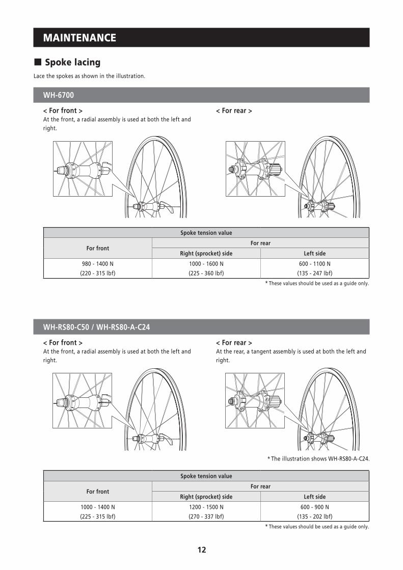
� Spoke lacingLace the spokes as shown in the illustration.
WH-6700
< For front > < For rear >At the front, a radial assembly is used at both the left and right.
Spoke tension value
For frontFor rear
Right (sprocket) side Left side
980 - 1400 N
(220 - 315 lbf)
1000 - 1600 N
(225 - 360 lbf)
600 - 1100 N
(135 - 247 lbf)
* These values should be used as a guide only.
WH-RS80-C50 / WH-RS80-A-C24
< For front > < For rear >At the front, a radial assembly is used at both the left and right.
At the rear, a tangent assembly is used at both the left and right.
* The illustration shows WH-RS80-A-C24.
Spoke tension value
For frontFor rear
Right (sprocket) side Left side
1000 - 1400 N
(225 - 315 lbf)
1200 - 1500 N
(270 - 337 lbf)
600 - 900 N
(135 - 202 lbf)
* These values should be used as a guide only.
13
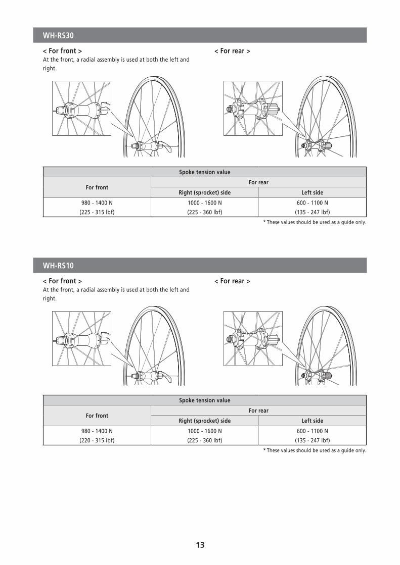
WH-RS30
< For front > < For rear >At the front, a radial assembly is used at both the left and right.
Spoke tension value
For frontFor rear
Right (sprocket) side Left side
980 - 1400 N
(225 - 315 lbf)
1000 - 1600 N
(225 - 360 lbf)
600 - 1100 N
(135 - 247 lbf)
* These values should be used as a guide only.
WH-RS10
< For front > < For rear >At the front, a radial assembly is used at both the left and right.
Spoke tension value
For frontFor rear
Right (sprocket) side Left side
980 - 1400 N
(220 - 315 lbf)
1000 - 1600 N
(225 - 360 lbf)
600 - 1100 N
(135 - 247 lbf)
* These values should be used as a guide only.
14
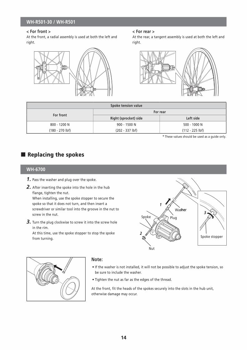
WH-R501-30 / WH-R501
< For front > < For rear >At the front, a radial assembly is used at both the left and right.
At the rear, a tangent assembly is used at both the left and right.
Spoke tension value
For frontFor rear
Right (sprocket) side Left side
800 - 1200 N
(180 - 270 lbf)
900 - 1500 N
(202 - 337 lbf)
500 - 1000 N
(112 - 225 lbf)
* These values should be used as a guide only.
� Replacing the spokes
WH-6700
1. Pass the washer and plug over the spoke.
2. After inserting the spoke into the hole in the hub flange, tighten the nut. When installing, use the spoke stopper to secure the spoke so that it does not turn, and then insert a screwdriver or similar tool into the groove in the nut to screw in the nut.
3. Turn the plug clockwise to screw it into the screw hole in the rim. At this time, use the spoke stopper to stop the spoke from turning.
1
2
Nut
PlugSpoke
WasherWasher
Spoke stopper
3
Note: • If the washer is not installed, it will not be possible to adjust the spoke tension, so be sure to include the washer.
• Tighten the nut as far as the edges of the thread.
At the front, fit the heads of the spokes securely into the slots in the hub unit, otherwise damage may occur.
15
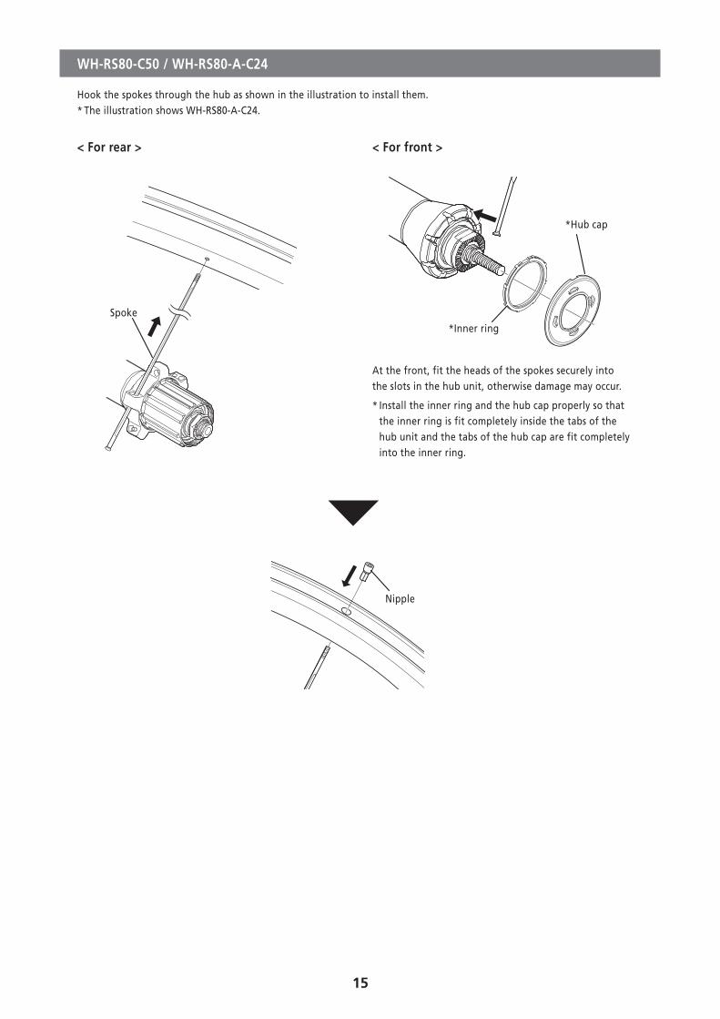
WH-RS80-C50 / WH-RS80-A-C24
Hook the spokes through the hub as shown in the illustration to install them.* The illustration shows WH-RS80-A-C24.
< For rear > < For front >
Spoke*Inner ring
*Hub cap
At the front, fit the heads of the spokes securely into the slots in the hub unit, otherwise damage may occur.
* Install the inner ring and the hub cap properly so that the inner ring is fit completely inside the tabs of the hub unit and the tabs of the hub cap are fit completely into the inner ring.
Nipple
16
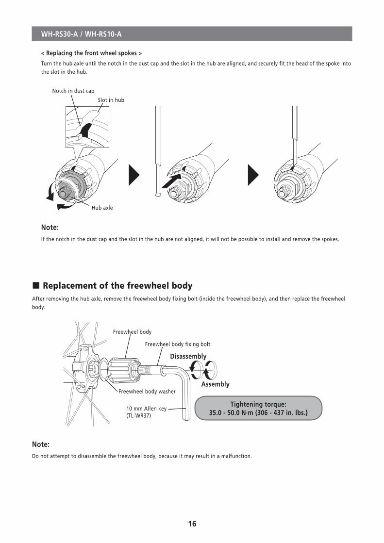
WH-RS30-A / WH-RS10-A
< Replacing the front wheel spokes >
Turn the hub axle until the notch in the dust cap and the slot in the hub are aligned, and securely fit the head of the spoke into the slot in the hub.
Notch in dust cap
Slot in hub
Hub axle
Note:If the notch in the dust cap and the slot in the hub are not aligned, it will not be possible to install and remove the spokes.
� Replacement of the freewheel bodyAfter removing the hub axle, remove the freewheel body fixing bolt (inside the freewheel body), and then replace the freewheel body.
Freewheel body
Freewheel body washer
Freewheel body fixing bolt
Disassembly
Assembly
10 mm Allen key (TL-WR37)
Tightening torque: 35.0 - 50.0 N·m {306 - 437 in. lbs.}
Note:Do not attempt to disassemble the freewheel body, because it may result in a malfunction.
17
� Installing and removing tubeless tires
TO ENSURE SAFETY
WARNING
• Read these Technical Service Instructions carefully, and keep them in a safe place for later reference.
CAUTION
• Do not use rim tape if using an inner tube either. Rim tape may make it difficult to remove and install the tire, and the tire or tube may become damaged or the tires may suddenly puncture and come off, and severe injury may result.
Note • The tires should always be installed and removed by hand. Never use tools such as tire levers, as they can damage the seal between the tires and the rims and cause air to leak out from the tires.
• Do not tighten the valve nut too much, otherwise the valve seal may become warped and air leaks may occur.
• If the tires are difficult to fit, use plan water or soapy water to help them slide more easily.
• Products are not guaranteed against natural wear and deterioration from normal use and aging.
Technical Service Instructions
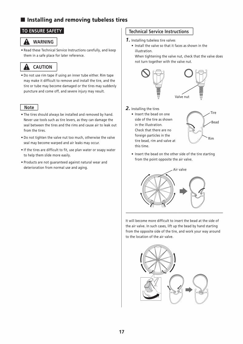
1. Installing tubeless tire valves • Install the valve so that it faces as shown in the illustration. When tightening the valve nut, check that the valve does not turn together with the valve nut.
Valve nut
2. Installing the tires • Insert the bead on one side of the tire as shown in the illustration. Check that there are no foreign particles in the tire bead, rim and valve at this time.
Tire
Bead
Rim
• Insert the bead on the other side of the tire starting from the point opposite the air valve.
Air valve
It will become more difficult to insert the bead at the side of the air valve. In such cases, lift up the bead by hand starting from the opposite side of the tire, and work your way around to the location of the air valve.
18
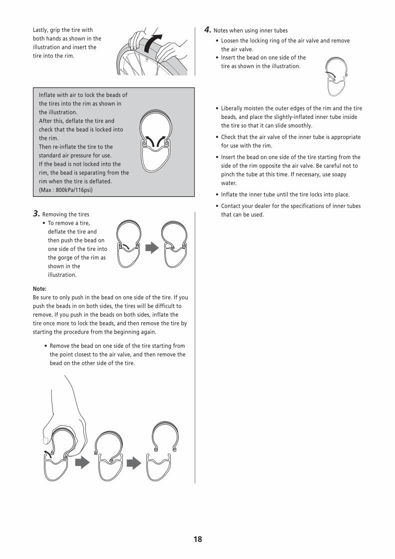
Lastly, grip the tire with both hands as shown in the illustration and insert the tire into the rim.
Inflate with air to lock the beads of the tires into the rim as shown in the illustration. After this, deflate the tire and check that the bead is locked into the rim. Then re-inflate the tire to the standard air pressure for use. If the bead is not locked into the rim, the bead is separating from the rim when the tire is deflated. (Max : 800kPa/116psi)
3. Removing the tires • To remove a tire, deflate the tire and then push the bead on one side of the tire into the gorge of the rim as shown in the illustration.
Note:Be sure to only push in the bead on one side of the tire. If you push the beads in on both sides, the tires will be difficult to remove. If you push in the beads on both sides, inflate the tire once more to lock the beads, and then remove the tire by starting the procedure from the beginning again.
• Remove the bead on one side of the tire starting from the point closest to the air valve, and then remove the bead on the other side of the tire.
4. Notes when using inner tubes
• Loosen the locking ring of the air valve and remove the air valve.
• Insert the bead on one side of the tire as shown in the illustration.
• Liberally moisten the outer edges of the rim and the tire beads, and place the slightly-inflated inner tube inside the tire so that it can slide smoothly.
• Check that the air valve of the inner tube is appropriate for use with the rim.
• Insert the bead on one side of the tire starting from the side of the rim opposite the air valve. Be careful not to pinch the tube at this time. If necessary, use soapy water.
• Inflate the inner tube until the tire locks into place.
• Contact your dealer for the specifications of inner tubes that can be used.

MTB
20
INSTALLATION
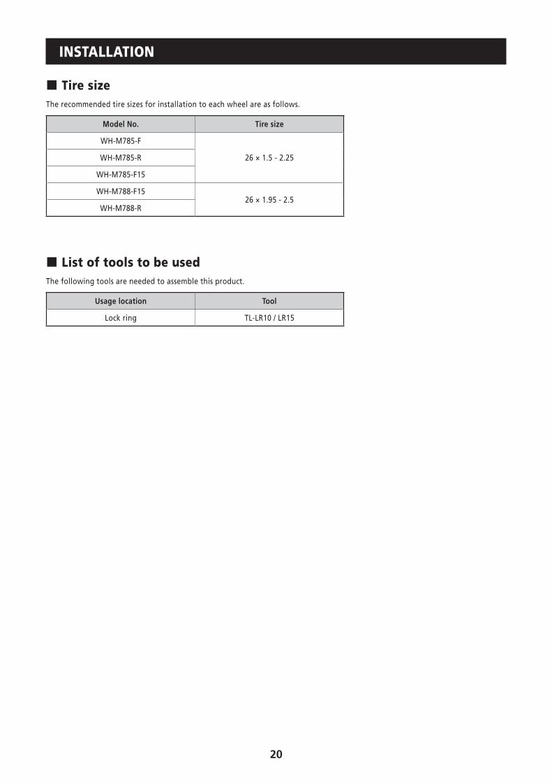
� Tire sizeThe recommended tire sizes for installation to each wheel are as follows.
Model No. Tire size
WH-M785-F
26 × 1.5 - 2.25WH-M785-R
WH-M785-F15
WH-M788-F1526 × 1.95 - 2.5
WH-M788-R
� List of tools to be usedThe following tools are needed to assemble this product.
Usage location Tool
Lock ring TL-LR10 / LR15
21
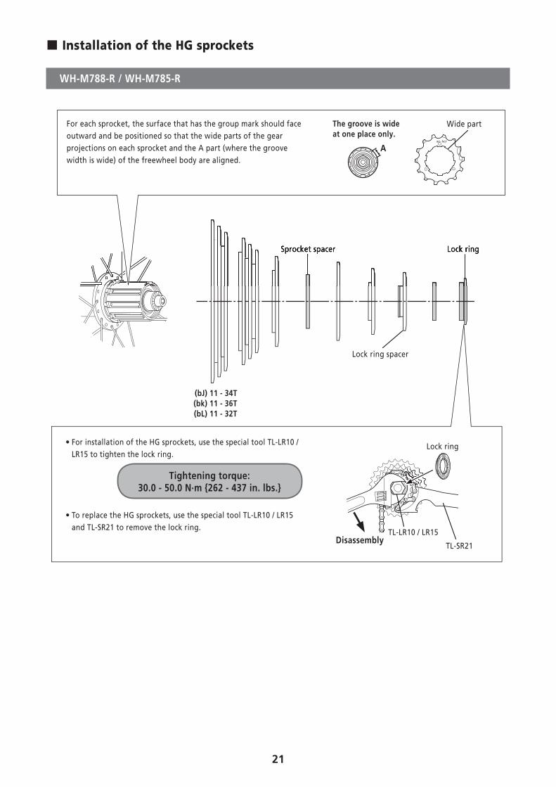
� Installation of the HG sprockets
WH-M788-R / WH-M785-R
• For installation of the HG sprockets, use the special tool TL-LR10 / LR15 to tighten the lock ring.
Tightening torque: 30.0 - 50.0 N·m {262 - 437 in. lbs.}
• To replace the HG sprockets, use the special tool TL-LR10 / LR15 and TL-SR21 to remove the lock ring.
TL-SR21
Lock ring
TL-LR10 / LR15Disassembly
Lock ringSprocket spacer
Lock ring spacer
(bJ) 11 - 34T(bk) 11 - 36T(bL) 11 - 32T
Lock ringSprocket spacer
For each sprocket, the surface that has the group mark should face outward and be positioned so that the wide parts of the gear projections on each sprocket and the A part (where the groove width is wide) of the freewheel body are aligned.
A
The groove is wide at one place only.
Wide part
22
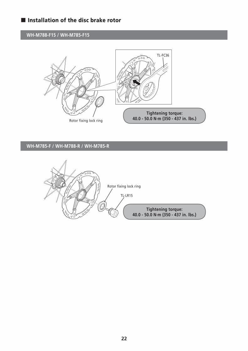
� Installation of the disc brake rotor
WH-M788-F15 / WH-M785-F15
TL-FC36
Rotor fixing lock ring
Tightening torque: 40.0 - 50.0 N·m {350 - 437 in. lbs.}
WH-M785-F / WH-M788-R / WH-M785-R
TL-LR15
Rotor fixing lock ring
Tightening torque: 40.0 - 50.0 N·m {350 - 437 in. lbs.}
23
MAINTENANCE
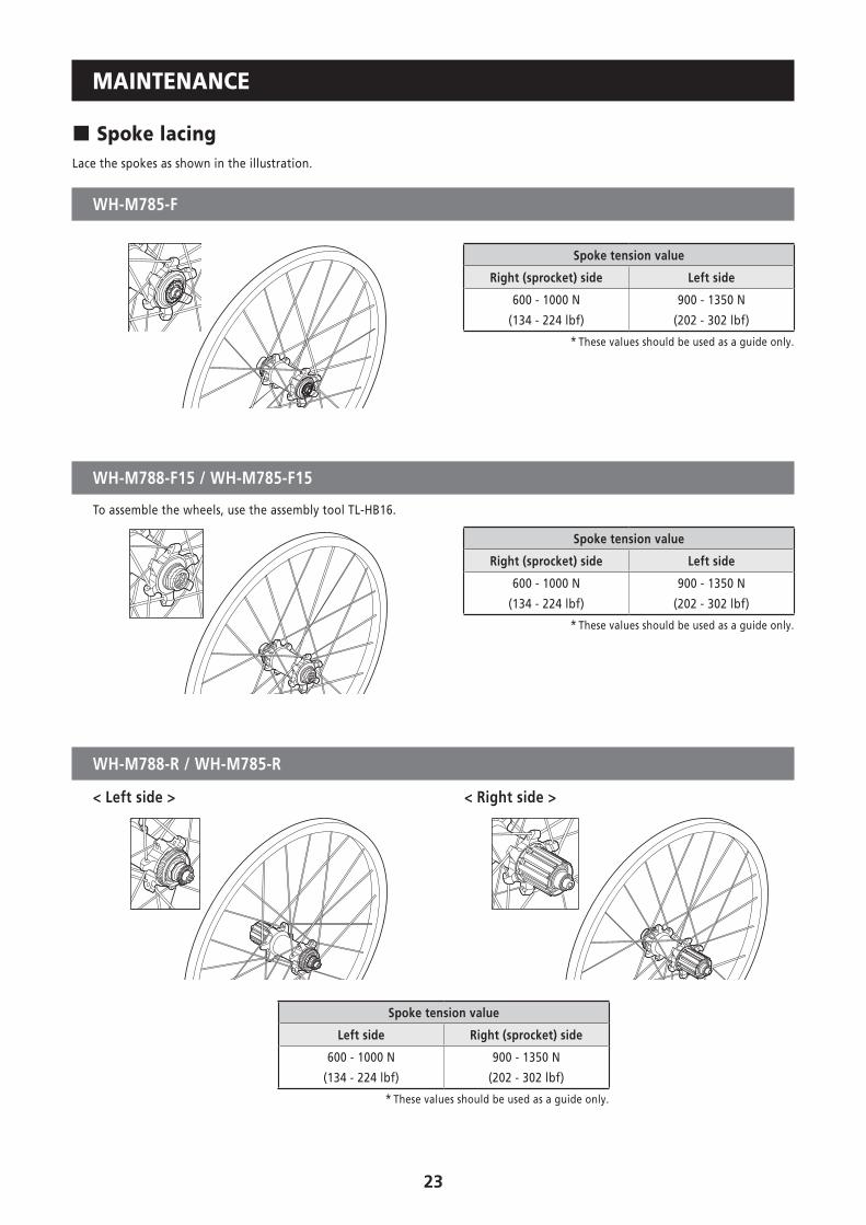
� Spoke lacingLace the spokes as shown in the illustration.
WH-M785-F
Spoke tension value
Right (sprocket) side Left side
600 - 1000 N
(134 - 224 lbf)
900 - 1350 N
(202 - 302 lbf)
* These values should be used as a guide only.
WH-M788-F15 / WH-M785-F15
To assemble the wheels, use the assembly tool TL-HB16.
Spoke tension value
Right (sprocket) side Left side
600 - 1000 N
(134 - 224 lbf)
900 - 1350 N
(202 - 302 lbf)
* These values should be used as a guide only.
WH-M788-R / WH-M785-R
< Left side > < Right side >
Spoke tension value
Left side Right (sprocket) side
600 - 1000 N
(134 - 224 lbf)
900 - 1350 N
(202 - 302 lbf)
* These values should be used as a guide only.
24
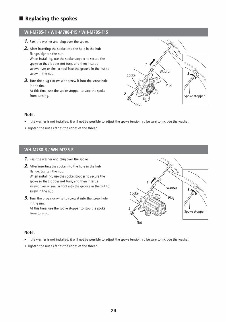
� Replacing the spokes
WH-M785-F / WH-M788-F15 / WH-M785-F15
1. Pass the washer and plug over the spoke.
2. After inserting the spoke into the hole in the hub flange, tighten the nut. When installing, use the spoke stopper to secure the spoke so that it does not turn, and then insert a screwdriver or similar tool into the groove in the nut to screw in the nut.
3. Turn the plug clockwise to screw it into the screw hole in the rim.At this time, use the spoke stopper to stop the spoke from turning.
1
2
Nut
Plug
SpokeWasher
Plug
Washer
Spoke stopper
3
Note: • If the washer is not installed, it will not be possible to adjust the spoke tension, so be sure to include the washer.
• Tighten the nut as far as the edges of the thread.
WH-M788-R / WH-M785-R
1. Pass the washer and plug over the spoke.
2. After inserting the spoke into the hole in the hub flange, tighten the nut. When installing, use the spoke stopper to secure the spoke so that it does not turn, and then insert a screwdriver or similar tool into the groove in the nut to screw in the nut.
3. Turn the plug clockwise to screw it into the screw hole in the rim.At this time, use the spoke stopper to stop the spoke from turning.
1
2
Nut
PlugSpoke
Washer
Plug
Washer
Spoke stopper
3
Note: • If the washer is not installed, it will not be possible to adjust the spoke tension, so be sure to include the washer.
• Tighten the nut as far as the edges of the thread.
25
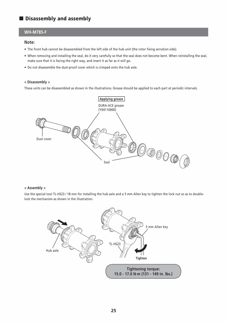
� Disassembly and assembly
WH-M785-F
Note: • The front hub cannot be disassembled from the left side of the hub unit (the rotor fixing serration side).
• When removing and installing the seal, do it very carefully so that the seal does not become bent. When reinstalling the seal, make sure that it is facing the right way, and insert it as far as it will go.
• Do not disassemble the dust-proof cover which is crimped onto the hub axle.
< Disassembly >
These units can be disassembled as shown in the illustrations. Grease should be applied to each part at periodic intervals.
Dust cover
Seal
Applying grease
DURA-ACE grease (Y04110000)
< Assembly >
Use the special tool TL-HS23 / 18 mm for installing the hub axle and a 5 mm Allen key to tighten the lock nut so as to double-lock the mechanism as shown in the illustration.
TL-HS23
5 mm Allen key
Hub axle
Tighten
Tightening torque: 15.0 - 17.0 N·m {131 - 149 in. lbs.}
26
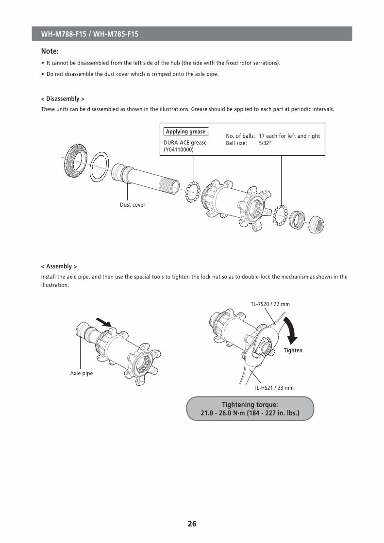
WH-M788-F15 / WH-M785-F15
Note: • It cannot be disassembled from the left side of the hub (the side with the fixed rotor serrations).
• Do not disassemble the dust cover which is crimped onto the axle pipe.
< Disassembly >
These units can be disassembled as shown in the illustrations. Grease should be applied to each part at periodic intervals.
Dust cover
Applying grease
DURA-ACE grease (Y04110000)
No. of balls: 17 each for left and rightBall size: 5/32”
< Assembly >
Install the axle pipe, and then use the special tools to tighten the lock nut so as to double-lock the mechanism as shown in the illustration.
TL-7S20 / 22 mm
TL-HS21 / 23 mm
Axle pipe
Tighten
Tightening torque: 21.0 - 26.0 N·m {184 - 227 in. lbs.}
27
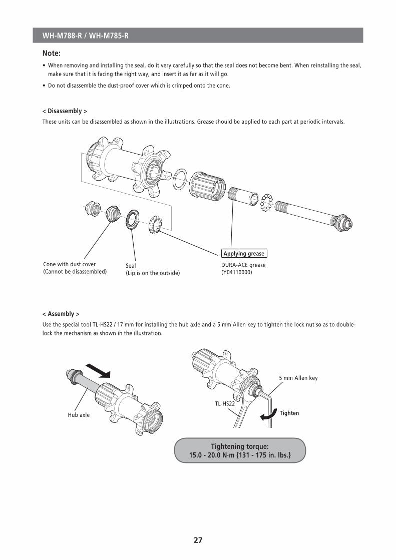
WH-M788-R / WH-M785-R
Note: • When removing and installing the seal, do it very carefully so that the seal does not become bent. When reinstalling the seal, make sure that it is facing the right way, and insert it as far as it will go.
• Do not disassemble the dust-proof cover which is crimped onto the cone.
< Disassembly >
These units can be disassembled as shown in the illustrations. Grease should be applied to each part at periodic intervals.
Cone with dust cover (Cannot be disassembled)
Seal (Lip is on the outside)
Applying grease
DURA-ACE grease(Y04110000)
< Assembly >
Use the special tool TL-HS22 / 17 mm for installing the hub axle and a 5 mm Allen key to tighten the lock nut so as to double-lock the mechanism as shown in the illustration.
TL-HS22
5 mm Allen key
Hub axle Tighten
Tightening torque: 15.0 - 20.0 N·m {131 - 175 in. lbs.}
28
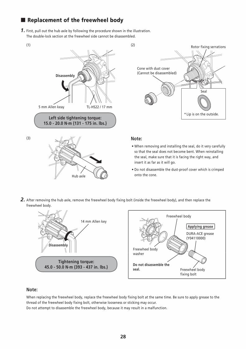
� Replacement of the freewheel body
1. First, pull out the hub axle by following the procedure shown in the illustration.The double-lock section at the freewheel side cannot be disassembled.
(1)
5 mm Allen keay TL-HS22 / 17 mm
Disassembly
(2)
Seal
* Lip is on the outside.
Rotor fixing serrations
Cone with dust cover (Cannot be disassembled)
Left side tightening torque: 15.0 - 20.0 N·m {131 - 175 in. lbs.}
(3)
Hub axle
Note: • When removing and installing the seal, do it very carefully so that the seal does not become bent. When reinstalling the seal, make sure that it is facing the right way, and insert it as far as it will go.
• Do not disassemble the dust-proof cover which is crimped onto the cone.
2. After removing the hub axle, remove the freewheel body fixing bolt (inside the freewheel body), and then replace the freewheel body.
14 mm Allen key
DisassemblyFreewheel bodywasher
Freewheel body
Do not disassemble the seal. Freewheel body
fixing bolt
Applying grease
DURA-ACE grease (Y04110000)
Tightening torque: 45.0 - 50.0 N·m {393 - 437 in. lbs.}
Note:When replacing the freewheel body, replace the freewheel body fixing bolt at the same time. Be sure to apply grease to the thread of the freewheel body fixing bolt, otherwise looseness or sticking may occur.Do not attempt to disassemble the freewheel body, because it may result in a malfunction.
29
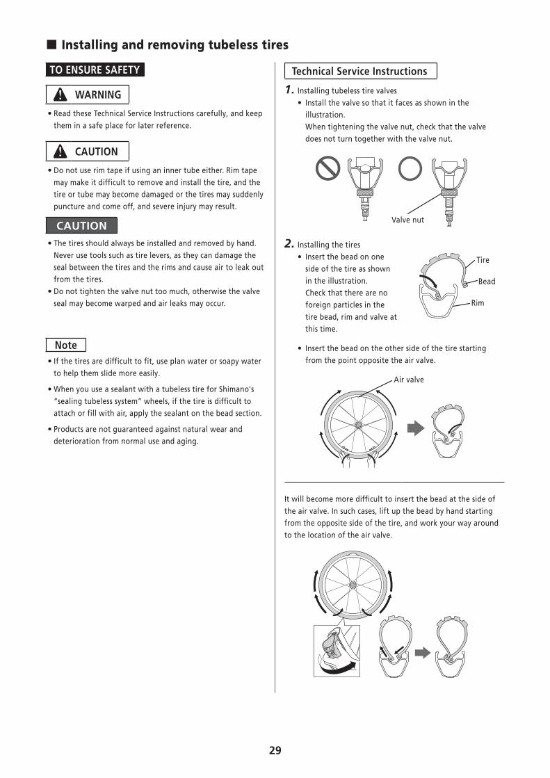
� Installing and removing tubeless tires
TO ENSURE SAFETY
WARNING
• Read these Technical Service Instructions carefully, and keep them in a safe place for later reference.
CAUTION
• Do not use rim tape if using an inner tube either. Rim tape may make it difficult to remove and install the tire, and the tire or tube may become damaged or the tires may suddenly puncture and come off, and severe injury may result.
CAUTION • The tires should always be installed and removed by hand. Never use tools such as tire levers, as they can damage the seal between the tires and the rims and cause air to leak out from the tires. • Do not tighten the valve nut too much, otherwise the valve seal may become warped and air leaks may occur.
Note • If the tires are difficult to fit, use plan water or soapy water to help them slide more easily.
• When you use a sealant with a tubeless tire for Shimano's “sealing tubeless system” wheels, if the tire is difficult to attach or fill with air, apply the sealant on the bead section.
• Products are not guaranteed against natural wear and deterioration from normal use and aging.
Technical Service Instructions
1. Installing tubeless tire valves • Install the valve so that it faces as shown in the illustration. When tightening the valve nut, check that the valve does not turn together with the valve nut.
Valve nut
2. Installing the tires • Insert the bead on one side of the tire as shown in the illustration. Check that there are no foreign particles in the tire bead, rim and valve at this time.
Tire
Bead
Rim
• Insert the bead on the other side of the tire starting from the point opposite the air valve.
Air valve
It will become more difficult to insert the bead at the side of the air valve. In such cases, lift up the bead by hand starting from the opposite side of the tire, and work your way around to the location of the air valve.
30
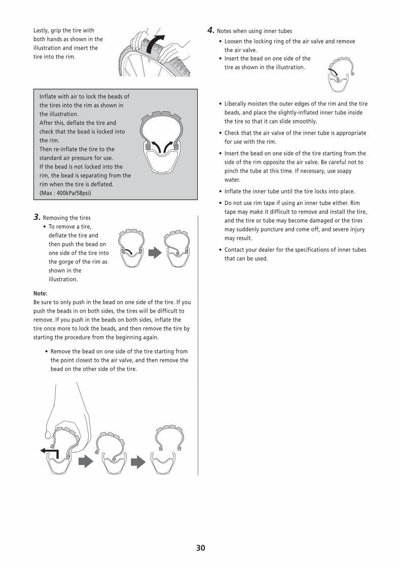
Lastly, grip the tire with both hands as shown in the illustration and insert the tire into the rim.
Inflate with air to lock the beads of the tires into the rim as shown in the illustration. After this, deflate the tire and check that the bead is locked into the rim. Then re-inflate the tire to the standard air pressure for use. If the bead is not locked into the rim, the bead is separating from the rim when the tire is deflated. (Max : 400kPa/58psi)
3. Removing the tires • To remove a tire, deflate the tire and then push the bead on one side of the tire into the gorge of the rim as shown in the illustration.
Note:Be sure to only push in the bead on one side of the tire. If you push the beads in on both sides, the tires will be difficult to remove. If you push in the beads on both sides, inflate the tire once more to lock the beads, and then remove the tire by starting the procedure from the beginning again.
• Remove the bead on one side of the tire starting from the point closest to the air valve, and then remove the bead on the other side of the tire.
4. Notes when using inner tubes
• Loosen the locking ring of the air valve and remove the air valve.
• Insert the bead on one side of the tire as shown in the illustration.
• Liberally moisten the outer edges of the rim and the tire beads, and place the slightly-inflated inner tube inside the tire so that it can slide smoothly.
• Check that the air valve of the inner tube is appropriate for use with the rim.
• Insert the bead on one side of the tire starting from the side of the rim opposite the air valve. Be careful not to pinch the tube at this time. If necessary, use soapy water.
• Inflate the inner tube until the tire locks into place.
• Do not use rim tape if using an inner tube either. Rim tape may make it difficult to remove and install the tire, and the tire or tube may become damaged or the tires may suddenly puncture and come off, and severe injury may result.
• Contact your dealer for the specifications of inner tubes that can be used.

Please note: specifications are subject to change for improvement without notice. (English) © Jan. 2013 by Shimano Inc. HTR


![No Model VIN 1 (DM) SANTAFE [DM] KMHSU81BSCU000212 2 … Engine YF and D… · 37 (dm) santafe [dm] kmhst81bsdu023920 38 (dm) santafe [dm] kmhst81bsdu023926 39 (dm) santafe [dm] kmhst81bsdu023930](https://static.fdocuments.us/doc/165x107/6017564e29e54a6dde7ebe6b/no-model-vin-1-dm-santafe-dm-kmhsu81bscu000212-2-engine-yf-and-d-37-dm-santafe.jpg)