What’s New In SA CHAPTER 1 - Kinematics
10
1 2020.12.01 Ribbon Menu Improvements Added full featured customizing of the SA Ribbon bar. This includes a search bar to help you find buttons, a hide and show control, the ability to create new tabs, groups and add new buttons as needed. It also provides the ability to link MP’s directly to new but- tons on any tab with a user defined icon. Ribbon Customization - https://youtu.be/RpfMloZ116s CHAPTER One of the advantages of SpatialAnalyzer is that devel- opment occurs at a brisk pace. New feature requests, bug fixes, and changes are implemented quickly, giving you the opportunity to start taking advantage of newly implemented features in a very short period of time. 1 What’s New In SA
Transcript of What’s New In SA CHAPTER 1 - Kinematics

1
2020.12.01
Ribbon Menu Improvements
Added full featured customizing of the SA Ribbon bar.
This includes a search bar to help you find buttons, a hide and show control, the ability to create new tabs, groups and add new buttons as needed. It also provides the ability to link MP’s directly to new but-tons on any tab with a user defined icon.
Ribbon Customization - https://youtu.be/RpfMloZ116s
CHA
PTER
One of the advantages of SpatialAnalyzer is that devel-opment occurs at a brisk pace. New feature requests, bug fixes, and changes are implemented quickly, giving you the opportunity to start taking advantage of newly implemented features in a very short period of time.
1What’s New In SA
2
SPATIALANALYZER USER MANUAL
GR-Feature Inspection Enhancements
New Auto Detect FeatureThis feature auto-detect the geometry type eliminating the need to predefine what geometry you are measuring. It also automatically sets the projection plane for you and auto-detects the nominal when pre-aligned to a CAD model. Adding an Auto-Detect Feature also au-tomatically sets the repeat flag when trapping so that you can simply press the next button to add additional features to the job.
This saves numerous trips back to the keyboard...
Autodetect Features: https://youtu.be/r45lkmfxczw
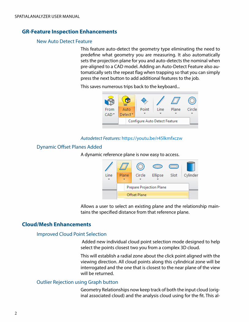
Dynamic Offset Planes AddedA dynamic reference plane is now easy to access.
Allows a user to select an existing plane and the relationship main-tains the specified distance from that reference plane.
Cloud/Mesh Enhancements
Improved Cloud Point Selection Added new individual cloud point selection mode designed to help select the points closest two you from a complex 3D cloud.
This will establish a radial zone about the click point aligned with the viewing direction. All cloud points along this cylindrical zone will be interrogated and the one that is closest to the near plane of the view will be returned.
Outlier Rejection using Graph buttonGeometry Relationships now keep track of both the input cloud (orig-inal associated cloud) and the analysis cloud using for the fit. This al-

3
CHAPTER 1 ■ WHAT’S NEW IN SA
lows you to use both Proximity Filtering and a new Graph button with a histogram display to process a cloud.
Expanded Proximity Filter Controls.GR-Features capable of performing a proximity filter now preserve the references to the input clouds. This enables edits to the filter set-tings to be made at any time. An Apply to Selection button can also be used to apply updated settings to other features, triggering a re-computation.
Feature Extract Settings: https://youtu.be/g9o7EvB-63o

4
SPATIALANALYZER USER MANUAL
Align to CADThe “Align Cloud to CAD” R-Click menu function will now auto-adjust the resolution of the CAD mesh to fit the size of the part. The default will be a mesh resolution to 10% of the maximum spatial extent of the surface.
If this fit is canceled and a retry attempted, the user can adjust this resolution manually. A larger value will result in a coarser CAD mesh to serve as an alignment target for the active cloud which translates to a shorter time required to generate the CAD mesh.
Cylindrical Cross SectionsThe cross section cloud configuration has been expanded to allow for the use of concentric cylinder definitions.
Cross Section clouds can now also be built dynamically from MP.
Demo available here: https://youtu.be/JbawRLRHpGE
Mesh Editing ExpansionIn this version a selection of additional commands have been added to facilitate mesh editing. These include
■ Dissect Mesh. Which allows you to break a mesh apart into its distinct pieces for editing or export.
■ Combine Selected Meshes. This command allows you to combine independent mesh elements into one.
■ Delete Selected Mesh Region. This option allows you to re-move unwanted segments of an existing mesh.
When combined with the existing hole fill, mesh stitching, and direct

5
CHAPTER 1 ■ WHAT’S NEW IN SA
STL export options, a fairly full featured mesh editing package is now available.
GD&T Enhancements
Expanded GD&T with GR-Features When selecting reference features in geometry relationship mode, the selection display now will by default expand the tree view.
When selecting reference features in geometry relationship mode, the nominal geometry will be used to establish the nominal tolerance value.
Additional Analysis Functions
Improved Backup StrategyModified strategy for saving job files such that a job with an existing job file will first be saved to a temporary file and if this operation suc-ceeds, then the existing job file will be deleted and the temporary job file will be renamed appropriately. Note that this temporary file will be written to the same directory as the original file so there must be enough disk space available in this directory for this operation to suc-ceed. If it fails or SA crashes during this operation, then the previous job file should still be valid as of the last time it was saved.
Added Locked PointsIn addition to the existing ability to lock the transform of surfaces and other SA objects, it is now possible to lock imported points such that they cannot be moved or measured over.
Import/Export Improvements
Improvements to Selective ImportThe selective import controls have been improved to make selection even easier. An Apply to all by type option has been added to allow a user to easily add or remove objects of a certain type by selecting a single item of that type. The include/exclude wildcard select filter has also be improved.

6
SPATIALANALYZER USER MANUAL
CAD import library update * Direct CAD Access Import:
- Updated Formats: ACIS 2020, CATIA V5-R2020, JT 10.3, Inventor 2021, NX 1899, Revit 2020, Parasolid v32.0
Cloud ImportE57 files can now be imported such as to optionally partition each file into a separate cloud, building a selection of individual clouds on a single import.
Reporting Enhancements
Added report table for ellipsoids which also supports callouts for ellipsoids. Reporting differentiates between general ellipsoids and those generated to represent uncertainty covariances. Also modified ellipsoid properties editor to expose settings for magnification scal-ing and optional flagging as an uncertainty ellipsoid.
Dimension DisplayPoint to object and object to object dimensions now have an option to include/exclude magnitude from component projections to a ref-erence frame when component selection is set to ALL.
Reports ExportAdded ability to select up to 100 SA reports to combine into a single PDF file.

7
CHAPTER 1 ■ WHAT’S NEW IN SA
Instrument Developments
The Instrument Quick Starts Guides have evolved into a new SA Instru-ments Manual which is now directly accessible from the Instrument Tab of the Ribbon Menu:
Laser Trackers“Pause at Beam Break” is now enabled by default for the standard “Spatial Points to SA” measure profile.
Faro Laser Trackers
Actively check if tracker needs an AutoComp during the startup se-quence, and run it if so.
Leica Automation Interface Control
Add message informing you that system configuration is needed if the AutomationInterface COM api cannot be created at startup.
Leica ATS600 Laser Tracker
Simplified measurement from the OVC - when the OVC is open, what-ever is showing in the OVC will always be Measured, no matter how the OVC was opened (from a profile definition or from the Drive Head/OVC control).
By request, always add a new Region or Line so that distance param-eters can be set separately for perimeters or points selected from SA. Previously, a new Region or Line was only added if none already ex-isted in the profile.
Nikon - Metris Laser RadarAdded support for double-clicking on the video window to zoom.
Surphaser ScannersThe SDK and support for the Surphaser Scanner has been greatly ex-panded including support for the Surphaser10:

8
SPATIALANALYZER USER MANUAL
■ Added ability to define the density of a scan at a given distance.
■ Added the ability to build a voxelize cloud and send it indepen-dently or in addition to the full cloud.
■ Expanded MP support.
Kreon (and API Axxis, Baces) ArmsUpdated SDK v.20.0.0.0 and support for the Kreon/API Axxis arm in-cluding an updated set of arm models.
Scanning mode (for all Kreon/Axxis arms) now starts paused, and scanning button functions are shown in the scan status window that opens automatically.
Scripting Enhancements
MP ImprovementsA “Refresh” option has been added to the “Run Subroutine” MP com-mand which can help in synchronizing arguments.
Added missing logging to many MP commands
See SA Readme for additional updates.
New MP Command: ■ Construct Point Cloud from Visible Cloud Points. Builds a
new cloud using a set of clipping plane definitions

9
CHAPTER 1 ■ WHAT’S NEW IN SA
■ Load Ribbon Bar from XML File. Loads a ribbon configuration file.
■ Reset Ribbon Bar to Default. Restores the default ribbon set-tings.
■ Verify MP File Exists. Allows verification that an embedded MP is available within a job file.
■ Set Point of View from Instrument Updates. Allows MP con-figuration of the instrument view.
■ Make Dynamic [ ] Relationship. Allows an MP to build a dy-namic point, line, Plane, Circle, Ellipse using any of the menu definitions.
■ Generate General Mesh. Builds a mesh from using the select-ed configuration.
■ Construct Mirror Cube Frame. Configures and builds a mirror cube frame.
■ Set Observation Collimation Shot Options. Allows an ob-servation within a point to be set as a collimation shot for an instrument.
■ Set Observation Mirror Cube Shot Face. Allows an observa-tion to be set as a mirror cube measurement.
■ Construct Line From Instrument Shot. Builds a line from an instrument shot and a measured point.
■ Import E57 File. Added support for E57 import from MP.
■ Construct Cross Section Cloud. Cross Section Clouds can now be defined and edited from MP.
■ Construct B-Spline Fit Options. B-Spline configurations can be now be adaptive and adjusted on the fly.
■ Mesh Volume. The volume of a mesh can now be computed with respect to a reference plane.
Modified “Construct Ellipsoid” to include additional parameters for setting magnification scaling and optional flagging as an uncertainty ellipsoid.
■ Construct TCP Fixture. Creates an entity that will compare newly measured points to reference nominal points to deter-mine the uncertainty covariance matrix with respect to the TCP frame.
■ Add Nominal Point to TCP Fixture. Provides an entry method for adding nominal points and their associated uncertainty co-variance matrices to the TCP Fixture.

10
SPATIALANALYZER USER MANUAL
■ Calculate TCP Fixture Uncertainties. this will process mea-sured points using closest point associations to TCP Fixture nominal points and a best-fit point-to-point transform per-formed wrt the TCP frame to determine the uncertainty covari-ance matrix wrt the TCP frame.
■ Get Last Solved TCP Fixture Uncertainty Covariance Matrix. Provides access to the last performed TCP Fixture uncertainty determination which can be used to set the instrument base uncertainties wrt instrument base using the “Set Instrument Base Uncertainty Covariance Matrix WRT Base” MP command.
■ Set Instrument Base Uncertainty Covariance Matrix WRT Base. Provides a method for setting the uncertainty covariance matrix for an instrument wrt the instrument base frame.
■ Set Instrument Base Uncertainty Covariance Matrix WRT WORLD. Provides a method for setting the uncertainty covari-ance matrix for an instrument wrt the WORLD frame.
■ Get Instrument Base Uncertainty Covariance Matrix WRT WORLD. Provides a method for retrieving the uncertainty co-variance matrix for an instrument wrt the WORLD frame.
■ Construct Measured Point Uncertainty Ellipsoids. Provides the capability for displaying the uncertainty covariance matrix for a measured point that is the combined uncertainty of the measurement wrt instrument base frame and the uncertainty of the instrument base wrt the WORLD frame. Using this func-tion allows the user to explore the results when uncertainty in-puts are varied.


![KINEMATICS - new.excellencia.co.innew.excellencia.co.in/college/web/pdf/Kinematics-merged.pdf · KINEMATICS KINEMATICS WORKSHEET 1 1) Displacement is a _____ [ ] 1) Vector quantity](https://static.fdocuments.us/doc/165x107/5f356d4687229051801abace/kinematics-new-kinematics-kinematics-worksheet-1-1-displacement-is-a-.jpg)