What's New in ESPRIT 2016 - MTTSmtts.net/library/ESPRIT/Whats New in ESPRIT 2016.pdf · What's New...
48
What's New in ESPRIT 2016
Transcript of What's New in ESPRIT 2016 - MTTSmtts.net/library/ESPRIT/Whats New in ESPRIT 2016.pdf · What's New...

What's New in ESPRIT 2016

Copyright © 2016 DP Technology Corp. All rights reserved.Information is subject to change without notice.No part of this manual may be reproduced, transmitted, translated in any form or by any means, graphic, electronic, or mechanical, including photocopying, recording, taping, or by any information storage or retrieval system, without written permission from DP Technology Corp.The software described in this document may only be used or copied in accordance with the terms of the furnished license agreement and/or non-disclosure agreement. It is illegal to copy the software onto any medium except as specified in the license or non-disclosure agreement.All DP Technology Corporation software products contain integrated security programs and/or plug-in modules that are required for the software license to properly operate. It is a violation of the DP Technology Corporation copyrights and U.S. Copyright law to disable or attempt to disable or remove or otherwise operate the software without the security programs and/or modules installed. Any software not supplied by DP Technology Corporation which is intended to allow the operation of the software without the required plug-in security module and/or integrated security programs is a copyright violation.ESPRIT is a registered trademark of DP Technology Corp.All brand or product names or proprietary file types mentioned in this document are trademarks or registered trademarks of their respective holders. Contact the appropriate companies for more information regarding trademarks and registration.DP Technology Corp.1150 Avenida AcasoCamarillo, California 93012USATel: +1 805 388 6000Fax: +1 805 388 3085www.espritcam.comPrinted in the United States of America
ContentsSystem enhancements ..................................................................................................... 4
Faster simulation ........................................................................................................ 4Data exchange .......................................................................................................... 4
CAD for Machining .......................................................................................................... 4New Smooth Surface command and new surface properties .............................. 4Edit a fillet on a solid model ...................................................................................... 6
Feature enhancements ................................................................................................... 7Auto Chain now recognizes properties of solid bodies .......................................... 7New Hole Recognition ............................................................................................... 8
Tooling enhancements ................................................................................................... 11Redesigned Tool Technology Pages ........................................................................ 11MachiningCloud Connect Add-In ..........................................................................12New Tool Model Setting ............................................................................................15Enhanced support for Barrel Tools ...........................................................................18
New ProfitTurning ........................................................................................................... 20ProfitTurning in SolidTurn Roughing ......................................................................... 20ProfitTurning in SolidTurn Grooving ......................................................................... 25
Milling enhancements ................................................................................................... 26Enhanced ProfitMilling ............................................................................................. 26New Minimize Stepover in Pocketing and Variable-Z Roughing .......................... 27
5-axis enhancements .................................................................................................... 28Constant Height incremental strategy in Swarf cycle ........................................... 28Blade cycles renamed to 5-Axis Spiral ................................................................... 29Part Surfaces Smoothing in 5-Axis Spiral Finishing ................................................. 29Fast Feed Clearance in 5-Axis Spiral Roughing ......................................................313D Tool Compensation ............................................................................................ 32Collision-free external links ..................................................................................... 33Rotary solutions for 5-axis external links ................................................................. 34
Wire EDM ......................................................................................................................... 35New Corner and Entry Witness Relief ..................................................................... 35Additional clearance on the cut-off ...................................................................... 36Ignore Radius on the rough cut .............................................................................. 36Optimize First Cut-off ................................................................................................37
What's New in the Post Processor .................................................................................. 38Redirect Output to Multiple Files ............................................................................ 38Helical output ........................................................................................................... 40Dynamic Arrays .........................................................................................................41Change values at runtime ...................................................................................... 42Other new keywords ................................................................................................ 43Updated keywords ................................................................................................... 45New math functions ................................................................................................. 46Post Processor Constants ......................................................................................... 48

What's New in ESPRIT 2016 | 4
System enhancementsAn upgraded simulation engine has enhanced the speed of simulations and data exchange is enhanced to support the import of Rhino 3dm files and Catia V6 3dxml files.
Faster simulat ionSimulation has been upgraded, resulting in speeds up to 14 times faster then before. The speed and reliability of stock automation has been upgraded as well.
Data exchangeESPRIT 2016 now supports:
• The import of Rhino 3dm files
• The import of sketch data from SolidWorks files (with the latest SolidWorks FX Add-in)
• The import of Catia V6 3dxml files version 2011x-2013
• ACIS files up to Version 21
• Parasolid files up to Version 28
CAD for MachiningAccurate toolpath relies on the accuracy and quality of the underlying model geometry. Since it may not be possible to use the original CAD system, ESPRIT offers functions to correct minor defects in a CAD model.
New Smooth Sur face command and new sur face proper t iesSometimes surfaces have micro-defects that are not noticeable at a glance. Geometric micro-defects can cause defects in the machining operations that use those surfaces. A typical example is when a surface is used as a drive surface for a Composite cycle.Figure 1. Toolpath analysis shows defects in the toolpath caused by micro-defects in a drive surface.
A new Smooth Surface transformation has been added to the Copy command.

What's New in ESPRIT 2016 | 5
Figure 2. Smooth Surface in the Copy dialog
Smooth Surface uses a smoothing algorithm to smooth and heal defective surfaces.Figure 3. Smoothing a micro-defect in a surface.
X Although ESPRIT already has the command Optimize (select a Surface, right-click Copy > Optimize), Smooth Surface was added to make it even simpler to correct surface defects (no need to set the surface u,v degrees) and is based on an enhanced smoothing algorithm.
New properties in the Property Manager display the total number of control points and dimensions in the U and V directions when a surface is selected.Figure 4. The properties of a smoothed surface can be compared in the Property Manager.

What's New in ESPRIT 2016 | 6
Edit a f i l let on a sol id modelA new Edit Fillet command makes it easier to modify or remove fillets on solid models.Figure 5. The new Edit Fillet command is available on the Solid Modeler toolbar.
Use this new command to make minor changes to a CAD model by removing fillet faces, changing the radius, or generating a spine curve along the center of the fillet radius.Figure 6. Selected faces display the current fillet radius value for easy evaluation.
X You can use face propagation to quickly group connected fillet faces. Any grouped faces will be added automatically to the Faces list when Edit Fillet is opened.
Figure 7. Remove fillets from the model to allow the tool radius to form the fillet during machining.
Figure 8. Change a fillet radius in ESPRIT instead of sending the CAD file for revisions.

What's New in ESPRIT 2016 | 7
Figure 9. Extract a spine curve to use as a drive curve in a machining operation.
Feature enhancementsAuto Chains recognize properties like depth, draft, and cutting side when created on solid models, and a new Hole Feature Recognition command has new options to recognize more types of complex holes on solid models.
Auto Chain now recognizes proper t ies of sol id bodiesDepth, draft angle and cut side are now calculated for planar features when solid elements (loop, edge, etc.) are selected. This behavior is similar to the previous Face Profiles command.Figure 1. Auto Chain now recognizes depth, draft angle and cut side from solid elements.
When the depth is recognized from a solid, Auto Chain generally uses the longest length of the shortest face in the loop.Occasionally the direction of selection can be ambiguous if the selection is not parallel to the active work plane. In previous versions of ESPRIT, the Face Profiles command would have created two features. Now, Auto Chain will find a floor or bottom and determine the feature direction automatically.This enhancement is especially useful when adjacent walls are curved instead of planar. In those cases, Auto Chain can be used instead of the Wall recognition command. However, the Blend Type is not recognized.

What's New in ESPRIT 2016 | 8
Figure 2. Auto Chain also recognizes the depth of curved walls.
New Hole Recognit ionHole Recognition is completely new, making it easier to recognize all types of drilled holes in solid models.Figure 3. New Hole Recognition automatically recognizes all types of holes and names them appropriately.
Recognized hole types:
• Simple holes
• Partial holes
• Complex holes
• Holes on different work planes

What's New in ESPRIT 2016 | 9
Figure 4. New Hole Recognition is available on the Create Features toolbar. The previous hole recognition command is still available as Legacy Hole Recogntion.
Recognition rules determine whether a cylindrical opening is recognized as a hole.Figure 5. Hole Recognition Options
Grouping options are applied after holes are recognized to determine how the holes should be grouped in the Feature Manager.
• Group all holes with one PTOP: Creates a single PTOP feature for all selected holes. This is useful when you want to center-drill all holes at one time, regardless of size.
Max. Diameter and Min. Diameter
Holes with diameters within the range defined by the Maximum Diameter and Minimum Diameter will be recognized. All other holes will be ignored. This is useful for excluding holes that are too large or too small to be drilled.

What's New in ESPRIT 2016 | 10
Min. Hole Opening Angle
This value determines whether partial holes are recognized based on the revolution angle of the hole.
Combine Coaxial Hole
This parameter determines whether interrupted holes that share an axis are recognized as one hole or separate holes.
Propagate Hole Faces
This parameter determines whether solid faces near the selected face are propagated.
Active Work Plane Only
This parameter determines whether holes are recognized based on the Z direction of the active work plane only.

What's New in ESPRIT 2016 | 11
Otherwise, holes are recognized regardless of direction.
Tooling enhancementsTool technology pages have been redesigned to be consistent with operation technology pages in ESPRIT. Plus, a new MachiningCloud Add-In allows direct communication between ESPRIT and the MachiningCloud App, to make it easy to import tool assemblies from leading cutting tool vendors into your ESPRIT document. Also, the support of barrel-shaped cutters has been extended to more freeform machining cycles.
Redesigned Tool Technology PagesThe technology pages for milling and turning tools have been redesigned to display a consistent interface for all tool types and are now embedded in the Project Manager to allow users to continue interacting with ESPRIT while entering tool data.Figure 1. Tool pages are now embedded in the Project Manager and consistent with operation pages.

What's New in ESPRIT 2016 | 12
MachiningCloud Connect Add-InNew commands on the File menu let you interact directly with the MachiningCloud App. The MachiningCloud App is the fastest way to find, select and assemble tools from leading cutting tool suppliers (download the app for free from https://www.machiningcloud.com).After the app is downloaded and installed, you can use the new MachiningCloud Connect Add-In to connect ESPRIT directly to your MachiningCloud Job data.Figure 2. The new MachiningCloud Connect Add-In connects ESPRIT directly to your MachiningCloud App.
Use the MachiningCloud App to select, define, and assemble your virtual cutting tools and then send your Machining Cloud Job to your computer.

What's New in ESPRIT 2016 | 13
Figure 3. Assemble your tools in the MachiningCloud App and then export your Job to ESPRIT.
Click Open a Machining Cloud Job to import and create the tools in ESPRIT for accurate collision detection during simulation.Figure 4. Import a MachiningCloud Job directly into ESPRIT to add the tools to the Tool Manager.

What's New in ESPRIT 2016 | 14
Figure 5. Simulate your virtual cutting tools in ESPRIT.
You can also transfer information about your parts to the MachiningCloud App to generate a list of recommended cutting tools.In ESPRIT, select the features you want to machine and click Send to MachiningCloud to export them to the MachiningCloud App.Figure 6. Send information about features from ESPRIT to the MachiningCloud App.
Import the machining features in the MachiningCloud App, choose your preferred machining strategy, select the recommended tool or one of the other alternative choices, and add them to the job. Then export the job to ESPRIT.

What's New in ESPRIT 2016 | 15
New Tool Model Set t ingThe new Tool Model Setting function on the Common Machining toolbar lets you add/modify/delete solid models of tool holders to your machine setup.Figure 7. Launching the application displays a dialog with a Turret Holder Tree View and the cutting tools currently mounted on each tool station.
Figure 8. Right-click the desired station to add or update a solid model of a turret holder.
Figure 9. Holders mounted on a turret.

What's New in ESPRIT 2016 | 16
Figure 10. Right-click the desired tool to add or update a solid model of a tool holder. An Offset can also be added to set the tool correctly onto the holder.
Figure 11. A tool holder mounted on a B-axis head.
Solid models of custom tool holders can be created in ESPRIT, saved as STL models and then imported as a tool holder in Tool Model Settings.Figure 12. Position a holder model in the orietation it will be mounted on the machine. Position a milling holder with the Z vector pointing along the tool axis and the attachment point at the origin of the global coordinate system.

What's New in ESPRIT 2016 | 17
Figure 13. The same principles apply to a turret holder. Position the model in the orientation it will be mounted on the machine, with the attachment point at the origin.
X The position of your models is for convenience and consistency. The position of the holder can be adjusted in the Tool Model Setting dialog.
Figure 14. The position of the holder, and the tool mounted in the holder, is easily adjusted in the Tool Model Setting dialog.
X The Tool Model Setting function adjusts the tool position by setting the Tool Shift XYZ value on the Tool page for each tool automatically. Please do not modify the Tool Shift XYZ values manually in the tool definition. Use the Tool Attached Positions or add an Offset to the tool using the Tool Model Setting instead. If you have to modify a Tool Parameter such as Tool Length, the Tool Shift Value will need to be re-calculated. To do this, simply re-launch the "Tool Model Setting" utility whenever such adjustments are made.

What's New in ESPRIT 2016 | 18
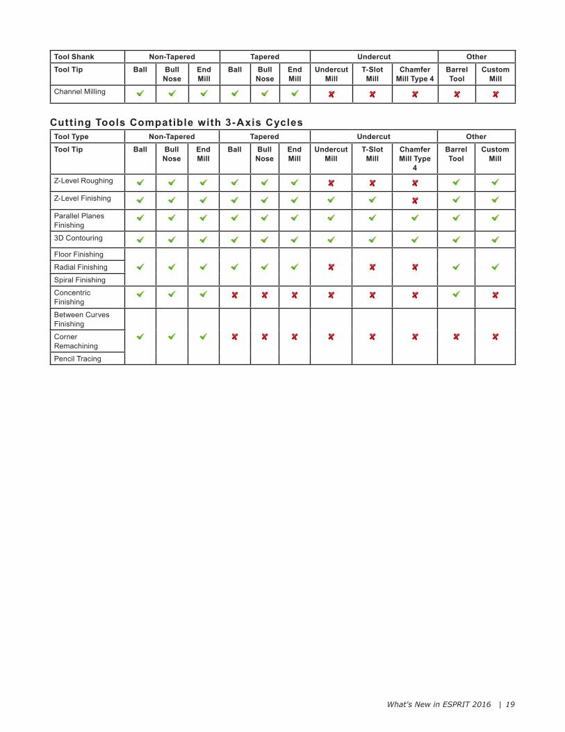
Enhanced suppor t for Barrel ToolsThe Barrel Tool is still supported by the 5-Axis Spiral Finishing cycle, where it is usually applied, but now it is supported by other 5 and 3 axis cycles.
• 5-Axis Spiral Roughing and Finishing
• 5-Axis Port Finishing
• 5-Axis Composite Milling
• 5-Axis Contouring
• 3-Axis Z-Level Roughing
• 3-Axis Z-Level Finishing
• 3-Axis Parallel Planes Finishing
• 3-Axis Floor FinishingThe following tables provide a summary of the tools supported by each 3-Axis and 5-Axis FreeForm cycle.
Cutting Tools Compatible with 5-Axis CyclesTool Shank Non-Tapered Tapered Undercut OtherTool Tip Ball Bull
NoseEnd Mill
Ball Bull Nose
End Mill
Undercut Mill
T-Slot Mill
Chamfer Mill Type 4
Barrel Tool
Custom Mill
Spiral Roughing & Finishing
Composite
Contouring
Contouring (Chamfering)
Impeller Milling
Port Finishing
Port Roughing
Swarf (Ruled)Profile Synchronization: All except Adapt TA to Best Fit
Swarf (Surfaces)Profile Synchronization: Adapt TA to Best Fit
What's New in ESPRIT 2016 | 19
Tool Shank Non-Tapered Tapered Undercut OtherTool Tip Ball Bull
NoseEnd Mill
Ball Bull Nose
End Mill
Undercut Mill
T-Slot Mill
Chamfer Mill Type 4
Barrel Tool
Custom Mill
Channel Milling
Cutting Tools Compatible with 3-Axis CyclesTool Type Non-Tapered Tapered Undercut OtherTool Tip Ball Bull
NoseEnd Mill
Ball Bull Nose
End Mill
Undercut Mill
T-Slot Mill
Chamfer Mill Type
4
Barrel Tool
Custom Mill
Z-Level Roughing
Z-Level Finishing
Parallel Planes Finishing
3D Contouring
Floor Finishing
Radial Finishing
Spiral Finishing
Concentric Finishing
Between Curves Finishing
Corner Remachining
Pencil Tracing

What's New in ESPRIT 2016 | 20
New ProfitTurningProfitTurning is a new lathe roughing strategy that blends trochoidal cutting passes with traditional linear passes to maintain a constant tool load, which is ideal for hard material machining. Trochoidal passes replace traditional cutting passes in sharp corners, and arcs are inserted wherever the tool touches a wall to allow the tool to roll in and out of the cut. The new ProfitTurning strategy is available in SolidTurn Roughing and as a roughing option in Grooving.
Prof i tTurning in Sol idTurn RoughingThree new ProfitTurning strategies have been added to the Roughing cycle to correspond with the existing traditional strategies.
• ProfitTurning - Parallel
• ProfitTurning - Offset
• ProfitTurning - AngleFigure 1. Three new ProfitTurning strategies are available in the Roughing cycle.
X The ProfitTurning strategy supports only cutting tools with circular inserts that are capable of cutting on both sides of the tool. Tool selection is limited to: full round groove tool, round turning insert, or any form/profile custom tool.
ProfitTurning is a high-speed roughing strategy that significantly reduces cycle times while increasing tool life. ProfitTurning replaces sharp transitions in the toolpath with rounded moves. The elimination of sharp changes in tool direction allows for consistently faster feedrates.
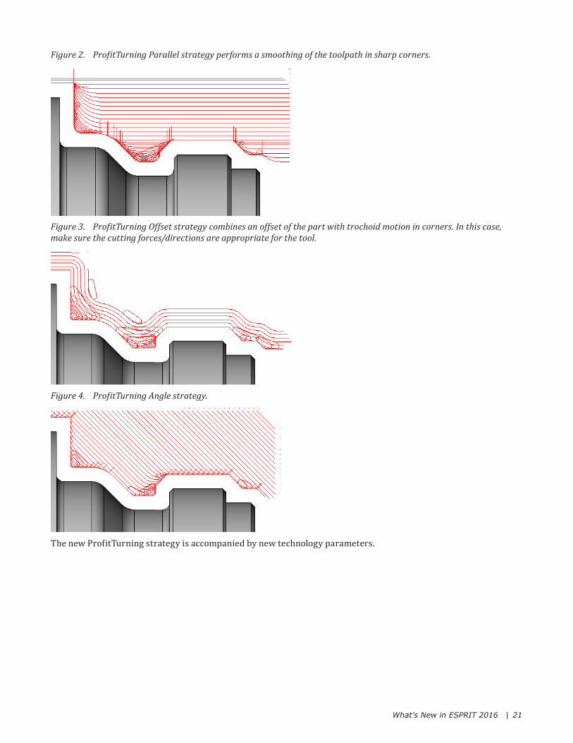
What's New in ESPRIT 2016 | 21
Figure 2. ProfitTurning Parallel strategy performs a smoothing of the toolpath in sharp corners.
Figure 3. ProfitTurning Offset strategy combines an offset of the part with trochoid motion in corners. In this case, make sure the cutting forces/directions are appropriate for the tool.
Figure 4. ProfitTurning Angle strategy.
The new ProfitTurning strategy is accompanied by new technology parameters.

What's New in ESPRIT 2016 | 22
Figure 5. New ProfitTurning technology parameters for the ProfitTurning strategy.
X When a ProfitTurning strategy is chosen, all parameters in the "Retract" group are hidden and "Retract % of Depth" is hard-coded to 110% and "Pullout Mode" is hard-coded to Along Feature. The system controls these parameters because unbalanced in/out moves will cause a problem for connecting adjacent passes in zig-zag mode.
Figure 6. Roll In/Out Radius adds an arc where each linear rough pass touches a wall.
Figure 7. Roll In/Out Feedrate is applied to the roll-in and roll-out arcs.
What's New in ESPRIT 2016 | 23
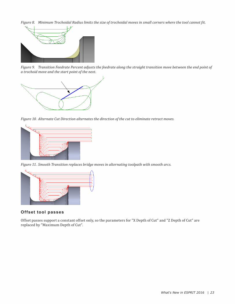
Figure 8. Minimum Trochoidal Radius limits the size of trochoidal moves in small corners where the tool cannot fit.
Figure 9. Transition Feedrate Percent adjusts the feedrate along the straight transition move between the end point of a trochoid move and the start point of the next.
Figure 10. Alternate Cut Direction alternates the direction of the cut to eliminate retract moves.
Figure 11. Smooth Transition replaces bridge moves in alternating toolpath with smooth arcs.
Offset tool passes
Offset passes support a constant offset only, so the parameters for "X Depth of Cut" and "Z Depth of Cut" are replaced by "Maximum Depth of Cut".

What's New in ESPRIT 2016 | 24
Figure 12. The ProfitTurning Offset strategy has slightly different parameters.
"Clearance Along Cut" is enhanced to create a clearance move based on the cutting conditions, rather than a parallel move. Depending on the situation, the clearance move could be one of four types:
• Tangent segment
• 90 degree tangent arc + segment
• Perpendicular segment
• Varying degree tangent arc + segmentFigure 13. Four types of clearance passes.
What's New in ESPRIT 2016 | 25
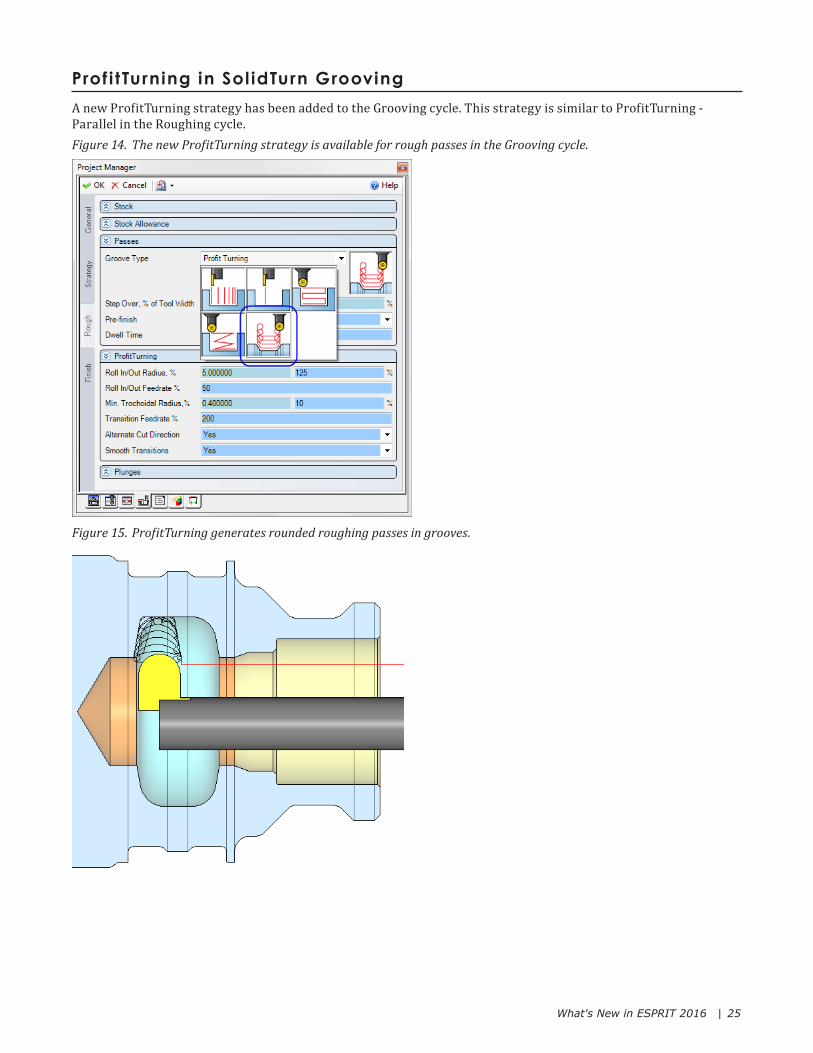
Prof i tTurning in Sol idTurn GroovingA new ProfitTurning strategy has been added to the Grooving cycle. This strategy is similar to ProfitTurning - Parallel in the Roughing cycle.Figure 14. The new ProfitTurning strategy is available for rough passes in the Grooving cycle.
Figure 15. ProfitTurning generates rounded roughing passes in grooves.
What's New in ESPRIT 2016 | 26
Milling enhancementsProfitMilling now features an adjustable width to better adapt trochoidal motion in pockets of all sizes and shapes. Plus, for pockets where high-speed toolpath is not possible, a new option will maintain a constant tool load in standard offset toolpath.
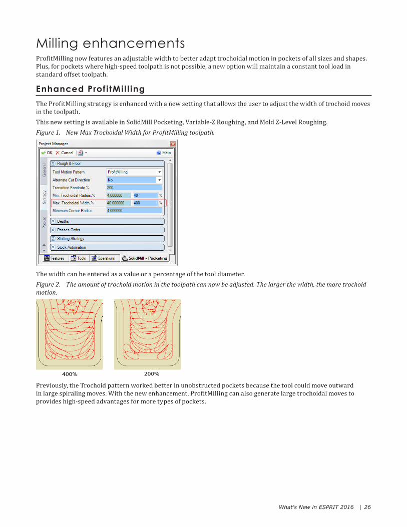
Enhanced Prof i tMi l l ingThe ProfitMilling strategy is enhanced with a new setting that allows the user to adjust the width of trochoid moves in the toolpath.This new setting is available in SolidMill Pocketing, Variable-Z Roughing, and Mold Z-Level Roughing.Figure 1. New Max Trochoidal Width for ProfitMilling toolpath.
The width can be entered as a value or a percentage of the tool diameter.Figure 2. The amount of trochoid motion in the toolpath can now be adjusted. The larger the width, the more trochoid motion.
Previously, the Trochoid pattern worked better in unobstructed pockets because the tool could move outward in large spiraling moves. With the new enhancement, ProfitMilling can also generate large trochoidal moves to provides high-speed advantages for more types of pockets.

What's New in ESPRIT 2016 | 27
Figure 3. Comparison of Trochoid and enhanced ProfitMilling toolpath.
New Minimize Stepover in Pocketing and Variable-Z RoughingThe Extra Moves setting has a new Minimize Stepover option that maintains a constant tool engagement in standard tool motion patterns.Figure 4. New Minimize Stepover option in Pocketing
Minimize Stepover will maintain the specified stepover whenever possible. This is useful for applications when maintaining a constant tool engagement is critical, but a high-speed machining cycle is not possible.Figure 5. Minimize Stepover maintains a constant tool engagement in offset toolpath
X Minimize Stepover is not available for high-speed tool motion like Trochoid or ProfitMilling.

What's New in ESPRIT 2016 | 28
5-axis enhancementsSwarf milling on complex walls is improved in ESPRIT 2016 with an option to apply a constant or adaptive incremental depth, eliminating unwanted plunge-type moves when the tool moves from high to low on walls that have varying heights. Blade cycles are now referred to as 5-Axis Spiral to better reflect the diversity of part geometry on which they can be applied. 5-Axis Spiral Roughing (formerly Blade Roughing) and 5-Axis Spiral Finishing (formerly Blade Finishing) are not only adept at machining blades, but medical prostheses, engine components and many more part geometries.
Constant Height incremental st rategy in Swar f cyclePreviously, the incremental depth passes of the Swarf cycle were always distributed by morphing the passes from the upper profile towards the lower profile. Now a new Increment Strategy setting lets the user choose a new Constant Height option.Figure 1. New Increment Strategy has two options: Constant Height and Morph.
Complex parts often have walls of varying heights. This height variation can result in plunge components in the toolpath, which should be avoided.Figure 2. Morph incremental passes adjust between upper and lower profiles, which can cause undesirable plunge-type motion as the tool moves from high to low.
The new Constant Height option will use a constant depth increment for all cutting passes.
What's New in ESPRIT 2016 | 29
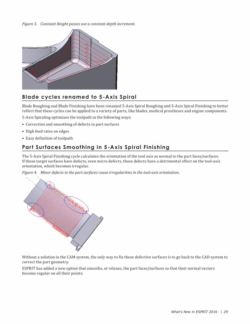
Figure 3. Constant Height passes use a constant depth increment.
Blade cycles renamed to 5-Axis Spi ralBlade Roughing and Blade Finishing have been renamed 5-Axis Spiral Roughing and 5-Axis Spiral Finishing to better reflect that these cycles can be applied to a variety of parts, like blades, medical prostheses and engine components.5-Axis Spiraling optimizes the toolpath in the following ways:
• Correction and smoothing of defects in part surfaces
• High feed rates on edges
• Easy definition of toolpath
Par t Sur faces Smoothing in 5-Axis Spi ral FinishingThe 5-Axis Spiral Finishing cycle calculates the orientation of the tool axis as normal to the part faces/surfaces. If those target surfaces have defects, even micro defects, those defects have a detrimental effect on the tool-axis orientation, which becomes irregular.Figure 4. Minor defects in the part surfaces cause irregularities in the tool-axis orientation.
Without a solution in the CAM system, the only way to fix these defective surfaces is to go back to the CAD system to correct the part geometry.ESPRIT has added a new option that smooths, or relaxes, the part faces/surfaces so that their normal vectors become regular on all their points.
What's New in ESPRIT 2016 | 30
Figure 5. The new option 'Part Surfaces Smoothing' smooths the part surfaces so that their normal vectors become regular on all their points.
X The smoothing only affects the tool-axis behavior. The tool positioning is always kept on the original part faces/surfaces.
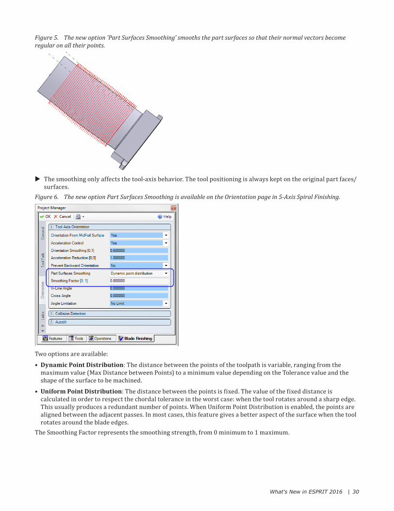
Figure 6. The new option Part Surfaces Smoothing is available on the Orientation page in 5-Axis Spiral Finishing.
Two options are available:
• Dynamic Point Distribution: The distance between the points of the toolpath is variable, ranging from the maximum value (Max Distance between Points) to a minimum value depending on the Tolerance value and the shape of the surface to be machined.
• Uniform Point Distribution: The distance between the points is fixed. The value of the fixed distance is calculated in order to respect the chordal tolerance in the worst case: when the tool rotates around a sharp edge. This usually produces a redundant number of points. When Uniform Point Distribution is enabled, the points are aligned between the adjacent passes. In most cases, this feature gives a better aspect of the surface when the tool rotates around the blade edges.
The Smoothing Factor represents the smoothing strength, from 0 minimum to 1 maximum.

What's New in ESPRIT 2016 | 31
Fast Feed Clearance in 5-Axis Spi ral RoughingThe Spiral Roughing cycle allows the feedrate to be increased when the tool loses contact with the material (non-cutting moves). Increasing the feedrate saves machining time in cases where cutting passes are interrupted, particularly when the Concentric cutting strategy is used. The feedrate is adjusted using the Max Feedrate Modifier % on the Tool Path page. Figure 7. Max Feedrate Modifier % increases the feedrate when the tool loses contact with the material.
Now a new setting has been added to the Links page that adds a safety distance to slow the motion from the fast feedrate of non-cutting sections of the toolpath to the conventional work feedrate when the tool is near the stock.Figure 8. The new Fast Feed Clearance parameter defines a safety distance for the transition between feedrates.
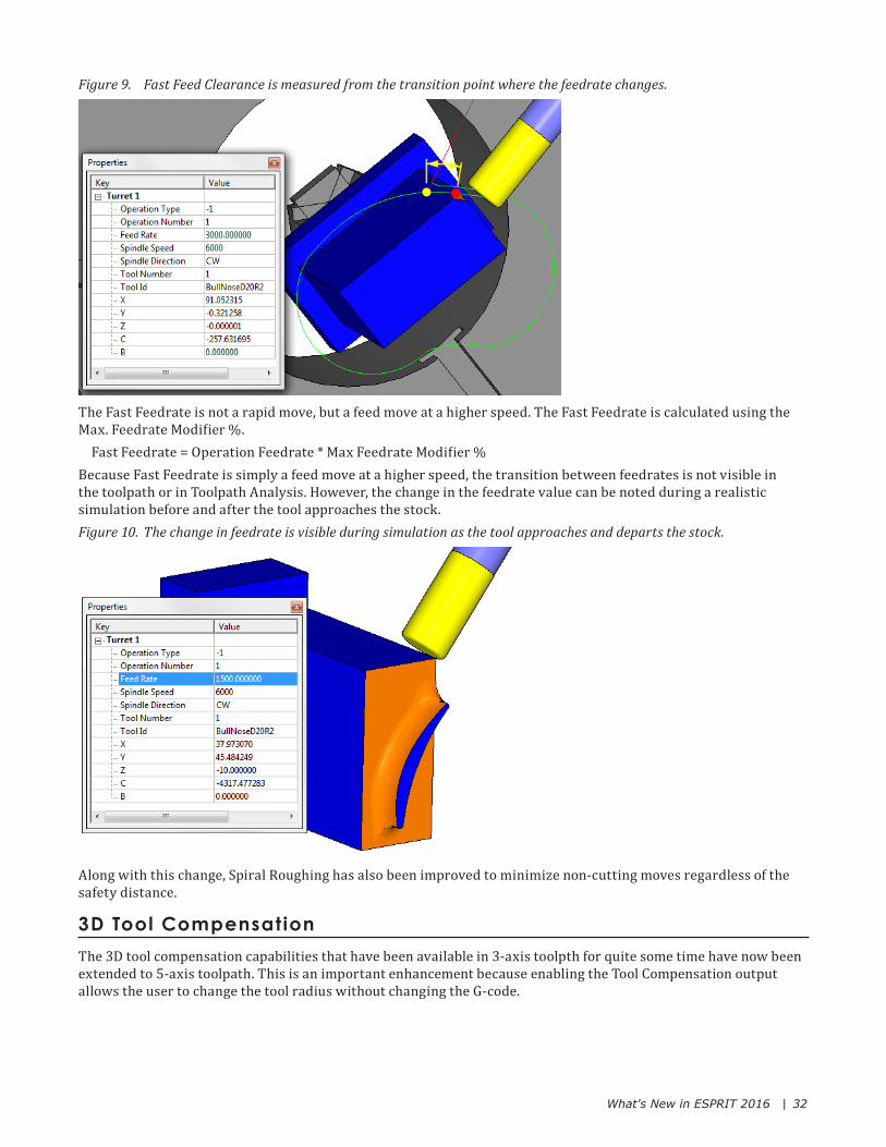
This clearance defines a safe height for the transition point where the feedrate changes between the Work Feedrate (for cutting moves) and the Fast Feedrate (for non-cutting link moves). Fast Feed Clearance is measured from the stock model, not the part.
What's New in ESPRIT 2016 | 32
Figure 9. Fast Feed Clearance is measured from the transition point where the feedrate changes.
The Fast Feedrate is not a rapid move, but a feed move at a higher speed. The Fast Feedrate is calculated using the Max. Feedrate Modifier %.
Fast Feedrate = Operation Feedrate * Max Feedrate Modifier %Because Fast Feedrate is simply a feed move at a higher speed, the transition between feedrates is not visible in the toolpath or in Toolpath Analysis. However, the change in the feedrate value can be noted during a realistic simulation before and after the tool approaches the stock.Figure 10. The change in feedrate is visible during simulation as the tool approaches and departs the stock.
Along with this change, Spiral Roughing has also been improved to minimize non-cutting moves regardless of the safety distance.
3D Tool CompensationThe 3D tool compensation capabilities that have been available in 3-axis toolpth for quite some time have now been extended to 5-axis toolpath. This is an important enhancement because enabling the Tool Compensation output allows the user to change the tool radius without changing the G-code.

What's New in ESPRIT 2016 | 33
Figure 11. Tool Compensation is now available in all 5-Axis finishing cycles except Impeller.
Tool Compensation is an option in:
• Composite Milling (only if "Tool Position" = Contact Point in Curve)
• Swarf
• 5-Axis Contouring
• Spiral Finishing
• Port FinishingWhen Tool Compensation is enabled, the toolpath is output as a set of touch point coordinates and normal vectors. The vectors associated with the Tool Compensation can be displayed by selecting "Touch Point-Normal" on the Tool Path page of the Masks Dialog (Ctrl-M).Figure 12. Toolpath vectors can be displayed in the graphics area.
X In the 5-Axis Composite and Port Milling cycles, tool compensation is limited to the "Contact point on Curve" option for the Tool Position setting (on the Tool Path page). In the 5-Axis Swarf cycle, tool compensation is not used when Profiles Synchronization is set to "Adapt TA for Best Fit".
Your machine format file must be able to accommodate the X, Y, and Z compensation vectors. The post keywords used to define the touch point are XSDim, YSDim, and ZSDim. The post keywords used to define the normal vector are ISDim, JSDim, and KSDim.
Coll is ion-f ree external l inksESPRIT 2016 has a new way of calculating external links when they are enabled in Machine Setup to avoid collisions with the entire solid body.When at least one 5-axis operation is involved, the system creates a collision-free external link with respect to all the solids for which at least one face is defined in the FreeForm Feature of the operation.

What's New in ESPRIT 2016 | 34
Now, if a 5-axis operation is the first or the last in the Operation Manager, the Transition Point must be located outside those solids; otherwise the links will fail.Figure 13. The Transition Point in external links must lie outside the solid model.
Rotary solut ions for 5-axis external l inksRotary positions for 5-axis operations are determined by the rotary axis position (first/second solution) at the end of the previous operation and at the beginning of the next operation. ESPRIT uses the minimum distance between operations to choose the rotary position. In some cases, depending on the part and tooling, automatic rotary calculation performed by ESPRIT may not be desirable, particularly when there are two possible solutions.5-axis operations now have a property called "Rotary Angles" in the Property Manager. Each rotary axis is displayed along with the possible rotary positions to reach the next operation. You can then choose the appropriate angle for the tool and/or part. This is useful when there are two or more ways to reach the next operation.Figure 14. Rotary Angles can be changed to other available options. When one rotary axis is changed, the other is automatically updated.

What's New in ESPRIT 2016 | 35
Wire EDMWire EDM has new strategies to improve the cut, especially on the rough cut.
New Corner and Ent ry Witness Rel iefIn high precision stamping tools and other applications that require tight tolerances, adding corner relief to the rough cut allows the skim cuts to follow the regular wire path without the need to reduce the feedrate in corners. Adding relief to the entry/witness also improves the cut without affecting the precision of the final geometry.New options will automatically modify the wire path to add relief to entries and internal/external corners on dies and open profiles. These new options do not apply to punches.Corner/Witness Relief is introduced on all EDM machine types except AgieVision and is located on the Advanced tab of the 2-Axis Contour operation page.Figure 1. New options on the Advanced tab let the user modify corners to add relief on die cuts.
When Corner/Witness Relief is enabled, a radius is added to the rough entry and sharp external corners of the rough wire path. The user has the option of adding a radius or chamfer to sharp internal corners.Figure 2. Relief is added to the entry and internal/external corners of the rough cut.
External corners that already have a radius are modified by adding extra clearance.

What's New in ESPRIT 2016 | 36
Addit ional clearance on the cut-of fIt can be useful to specify an additional clearance to only the cut-off pass. Now an additional clearance can easily be specified for the cut-off move only, in addition to the operation clearance.For a non-cutting punch (external block) or non-cutting die (guide) profile, the profile can be "damaged" without losing the main feature (position and orientation). It can be useful to specify an additional clearance to only the cut-off pass to prevent the need for additional grinding.Figure 3. Additional Clearance can be specified for the cut-off only.
When the Machining Strategy includes a cut-off, an additional clearance can be added or subtracted only to the cut-off pass.Figure 4. Clearance added to the cut-off. Additional clearance is available for all cut types (open, die, punch).
X Additional Clearance is not available when Skim Cut-Off is set to Yes.
Ignore Radius on the rough cutWhen a radius entry is used on a die, the movement of the wire can produce a small cusp of material (or burr) at the entry point.To prevent the burr, the entry/exit on the rough pass can be converted to a direct move without affecting the radius entry/exit of skim passes.When any of the following entry/exit types are selected for a die profile, the new Ignore Radius parameter is available:
• Radius
• Radius Normal
• Position Radius
• Position Radius Normal
What's New in ESPRIT 2016 | 37
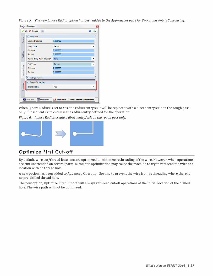
Figure 5. The new Ignore Radius option has been added to the Approaches page for 2-Axis and 4-Axis Contouring.
When Ignore Radius is set to Yes, the radius entry/exit will be replaced with a direct entry/exit on the rough pass only. Subsequent skim cuts use the radius entry defined for the operation.Figure 6. Ignore Radius create a direct entry/exit on the rough pass only.
Optimize Fi rst Cut-of fBy default, wire cut/thread locations are optimized to minimize rethreading of the wire. However, when operations are run unattended on several parts, automatic optimization may cause the machine to try to rethread the wire at a location with no thread hole.A new option has been added to Advanced Operation Sorting to prevent the wire from rethreading where there is no pre-drilled thread hole.The new option, Optimize First Cut-off, will always rethread cut-off operations at the initial location of the drilled hole. The wire path will not be optimized.

What's New in ESPRIT 2016 | 38
Figure 7. Optimize First Cut-off is a new option in Advanced Operation Sorting.
What's New in the Post ProcessorFor those who would like to customize, edit or develop the ESPRIT post processor, please review all the changes in ESPRIT 2016.
Redirect Output to Mult iple Fi lesInstead of generating one output file per post processor, it is now possible to redirect the output inside a single post processor to different files.This new feature can be used for a variety of applications.
• Generate one file per program when outputting sub programs
• Generate one file per operation or per tool for large operations (3-axis and 5-axis)
• Generate technology files or command files for EDM
BeginRedirect(FileName as string)
BeginRedirect is a new keyword that redirects the output of the post processor to the specified file name.Ex_CycleStart : BeginRedirect(OperationFileName)
BeginRedirect must be placed on a line by itself with no other instructions. Unless the full path is specified for FileName, output occurs in the same folder as the main NC output file. If the path includes a non-existent sub-directory, the system creates the directory.BeginRedirect runs a new function, called MakeValidPath, to automatically strip out any invalid characters from the FileName.
X In case of multiple redirections to the same file, the first redirect will overwrite the file if it exists. Successive redirections happen to the file without overwriting what was already added.

What's New in ESPRIT 2016 | 39
EndRedirect
EndRedirect is a new keyword that stops redirection of the NC output. Output is reset back to the NC File Name specified in the NC Output File dialog.Ex_CycleEnd : EndRedirect
EndRedirect must be placed on a line by itself with no other instructions.
MakeValidPath
MakeValidPath is a new function that automatically strips out characters that are invalid for a Windows file path. MakeValidPath is run automatically by the BeginRedirect keyword to ensure that redirected file paths are valid.Examples of invalid characters:
• < (less than)
• > (greater than)
• : (colon)
• " (double quote)
• / (forward slash)
• | (vertical bar)
• ? (question mark)
• * (asterisk)
NCFileName as string, NCFilePath as string
NCFileName is a new system variable that returns the NC File Name from the NC output definition.NCFilePath is a new system variable that returns the NC File Folder from the NC output definition.
Generating a list of all NC f iles created
Gp.exe accepts an additional argument to return the list of all NC files that have been created.From the command line, run:Gp.exe ClFile.tmp Post.pst Output.nc FileName.txt

What's New in ESPRIT 2016 | 40
Helical outputHelical output has been simplified so that helical motion with more than 1 revolution can now be output in a single block.
New MaximumHelicalTurns System Variable
MaximumHelicalTurns sets how many full 360 degree turns are allowed. For example, the machine might be limited to 99 revolutions on a single line.MaximumHelicalTurns : 99
MaximumHelicalTurns provides an easy way to switch between:
• No helical output (MaximumHelicalTurns=(0))
• Helical motion of 360 degrees maximum (MaximumHelicalTurns=(1))
• Multiple revolution helix (MaximumHelicalTurns=(99))
ExampleMaximumHelicalTurns : 99
Ex_Setup : HelixOutput=(2) ## 0=Helical motion interpolated with linear motions ; 1=Helical motion up to 360deg ; 2= Full support with G2/3 P
: If (HelixOutput=0) MaximumHelicalTurns=(0)
: ElseIf (HelixOutput=1) MaximumHelicalTurns=(1)
: EndIf
New Formatable Codes
AngleIncrement is the (End angle - Start Angle) of circular motion. If more than 1 revolution, this value is more than 360 degrees.AngleIncrement : DA N 4 Y N 3 N 4 Y N 3 1 1 N 0 0
HelicalFullTurns is the number of full turns within helical motion. HelicalFullTurns is output only when helical motion is greater than 360 degrees.HelicalFullTurns : TURNS= N 2 N N 0 N 2 N N 0 1 1 N 0 0
ExampleHelices are output with Ex_Circle, Ex_CircleZX, Ex_CircleYZ independently of the number of revolutions.Ex_Circle : IF (NextMisc(411)>0) ## HELICALFULLTURNS
: "(Output Helix Commands)"
: $OutputSequenceNumber WorkPlaneCode* CircleDirection* Absolute \\
XAbsolute YAbsolute ZAbsolute RotaryAxis1 RotaryAxis2 \\
XCenterAbsolute YCenterAbsolute ZCenterAbsolute \\
AngleStart AngleEnd AngleIncrement HelicalFullTurns \\
FeedUnit FeedRateCode
: ELSE ## regular circle
...
: ENDIF

What's New in ESPRIT 2016 | 41
Dynamic ArraysDynamic arrays (for single dimensions only) are now supported. Arrays let you store groups of related values.In the example below, an array with a fixed size (99 with a lower bound of 0) is used to store tool IDs so that they can be recalled later to look ahead and output the id of the next tool.Variable : ToolID(99) ToolCount TotalToolCount
ex_FirstToolChange : ToolCount=(ToolCount+1)
: OutputString("(CHANGING TO " + ToolID(ToolCount) + ")")
: T* M06*
: If (ToolCount < TotalToolCount)
: OutputString("(Next TOOL IS " + ToolID(ToolCount+1) + ")")
: T*(NextTool)
: Else
: OutputString("(THIS IS THE ONLY TOOL USED)")
: EndIf
Now the size of an array can be dynamic.Variable : MyArray1(*) ## declares a dynamic array with a lower bound of 0
Variable : MyArray2(-4..*) ## declares a dynamic array with a lower bound of -4
To populate a dynamic array:Ex_... : MyArray1(4)=(52.1) ## If array is not big enough, it is resized
: MyArray2(-1)=(12.5) ## If array isn't big enough, it is resized
New LBound and UBound functions
The Lbound and UBound functions are used to determine the size of an array.
• Use the UBound function to find the upper limit of an array dimension
• Use the LBound function to find the lower limit of an array dimensionExample:Variable : MyVar
Ex_... : MyVar=(LBound(MyArray1))
: MyVar=(UBound(MyArray1))
New Minimum and Maximum functions
Minimum() and Maximum() can take an array (or several arrays) as an argument. If the array is a dynamic array, elements of the array that are not initialized will not be included in the computation. If the array is of a fixed size type, all the elements are initialized to 0.0 when the array is created.Example:Variable : FixedArray(5) ## declares a fixed size array with a lower bound of 0
## all values initialized to 0.
: DynArray(*) ## declares a dynamic sized array - initial size is 0.
## no values are ever initialized.
Variable : MyVar
Ex_... : FixedArray(0)=(12.4)
What's New in ESPRIT 2016 | 42
: FixedArray(1)=(15.7)
: FixedArray(4)=(9.3)
: DynArray(0)=(12.4)
: DynArray(1)=(15.7)
: DynArray(4)=(9.3)
: MyVar=(Minimum(FixedArray)) ## MyVar will be 0 - because all array elements were
## initialized to 0.0
: MyVar=(Minimum(DynArray)) ## MyVar will be 9.3 - because no elements are
## pre-initialized.
Change values at runt imeValues can now be changed during runtime of the post for machine modes, formatable codes, and symbolic codes.
Change the value of a machine mode at run time
Example:Ex_BeforeCycle: RPYAngleMode(YawPitchRoll)
SetSymbolicCode
Change the symbol of the symbolic code at run time.Syntax:SetSymbolicCode(SymblicCode,"New Code")Example:SetSymbolicCode(SpindleCW, "M203")
SetFormatableSymbol
Change the symbol of a formatable code at run time.Syntax:SetFormatableSymbol(FormatableKeyword, Symbol)Example:Ex_CycleStart : SetFormatableSymbol( XAbsolute , "XHP" )
SetFormatableInch, SetFormatableMetric, SetFormatableZero
Control the number of leading and trailing digits before and after the decimal for inch, metric, and zero value output.Syntax:SetFormatableInch (FormatableKeyword , DigitsBeforeDecimal , DigitsAfterDecimal)
SetFormatableMetric (FormatableKeyword , DigitsBeforeDecimal , DigitsAfterDecimal)
SetFormatableZero (FormatableKeyword , DigitsBeforeDecimal , DigitsAfterDecimal)
Example:Ex_Setup : SetFormatableInch( XAbsolute , 4 , 6 )

What's New in ESPRIT 2016 | 43
SetFormatableMaximum, SetFormatableMinimum
Cap the value output by a formatable code. If the formatable code value is bigger than the maximum, then this maximum value is output instead.SetFormatableMinimum works the same way to set a minimum value on a formatable code.Syntax:SetFormatableMaximum(FormatableKeyword, MaximumValue)
SetFormatableMinimum(FormatableKeyword, MinimumValue)
Example:Ex_Setup : SetFormatableMaximum(InverseTimeFeed, 9999)
Other new keywordsIn addition to the enhancements implemented in ESPRIT 2016, several other new keywords have been added.
! to suppress output
It is often the case with a tool spindle axis that the axis needs to move but its motion is not explicit in the NC code.If the axis is part of the link motion, do not omit outputting its position. Instead, post its position using the new suppressed output format.! is a special keyword that applies to symbolic codes, symbolic switches, formatable codes, and formatable switches used in the examples section.Example:AAxis : C N 4 Y N 3 N 4 Y N 3 1 1 N 0 0
CoolantOff : M9
Ex_Before_Cycle : C!(0) ## This is the same as: NCOutputOff C(0) NCOutputOn
Ex_ToolCancel : M9! ## Coolant off code is not posted
ForceMisc
ForceMisc is a new system variable similar to ForceDim except that ForceMisc will not force the output of a soft example.ForceMisc takes a formatable miscellaneous register index number for an argument. The formatable miscellaneous that corresponds to that register will then be forced the next time it is output, even if the value has not changed and its output was not normally forced with an asterisk (*).Example: Forcing output of clamp code of axis 1 after a tool changeForceMisc (401)=(1)
EspritVersion
EspritVersion is a new system variable that returns the build number of the ESPRIT document. The version can be output as a string in the NC code.OutputString( "V(" + EspritVersion + ")" )
Example:Ex_StartCode : ProgramNumber*
: "(ESPRIT BUILD: " EspritVersion ")"
Result:(ESPRIT BUILD: 19.15.150.2189)

What's New in ESPRIT 2016 | 44
FeedrateMode: distance/min versus degree/min
When performing a feed motion of a rotary axis without RTCP or an inverse time feedrate, the feedrate value in the NC code is interpreted by most machines as an angular velocity in degree/minute. If the F value is not recalculated for the NC code, it can lead to disastrous results on the machine.ESPRIT can now calculate the F value for the NC code so that the programmed feedrate in the operation page corresponds to the cutting speed in the moving direction of the tool.If using this mode, the Feedrate values in the NC code will not match the programmed value in the operation page every time a rotary axis moves within a motion block.The new machine mode FeedrateMode controls how feedrate values are output:
• If FeedrateMode is equal to DistancePerMinute, then no special computation occurs. The feedrate in the NC code matches the programmed feedrate in the operation page. The feedrate value in the NC code is always the linear feedrate of the tool relative to the part.
• If FeedrateMode is equal to DistanceAndDegreePerMinute, then ESPRIT calculates the feedrate value for the NC code using the formula below. If a rotary axis moves by itself, then the output value unit is degree/minute.
• If FeedrateMode is not set, the default value is DistancePerMinuteFeedrate calculation for FeedrateMode = DistanceAndDegreePerMinuteFind (1): f = DL / T (1)Where:
• f(mm/min | in/min) = Cutting Feedrate
• DL(mm | in) = Cutting Length in Part. This is the length of the tool path item in ESPRIT
• T(s) = CuttingtimeFind (2): F = L / T (2)Where:
• F = Feedrate in NC program
• L = Moving Length for controller (different from cutting length on part)Find: L = sqrt( DX2+DY2+DZ2+DA2+DB2+DC2 ) (3)Where:
• DX, DY, DZ (mm | in) = length of motion per axis
• DA, DB, DC (degree) = angular displacement per rotary axisCombining (1) and (2):F = f * L / DLF is the feedrate value that ESPRIT dumps to the post for the formatable code Feedrate if the Feed Unit is set to (mm/min | in/min).If only linear axes moved then (L/DL) = 1 and F = fIf a rotary axis moves by itself then F value ends up as deg/min.

What's New in ESPRIT 2016 | 45
InverseTimeFeedUnit
InverseTimeFeedUnit is a new machine mode that controls the unit for the value output with formatable code InverseTimeFeed.
• If InverseTimeFeedUnit is equal to InverseTimeFeedPerMinute then value of InverseTimeFeed corresponds to the inverse of the time, in minutes, it takes to complete the motion.
• If InverseTimeFeedUnit is equal to InverseTimeFeedPerSecond then value of InverseTimeFeed corresponds to the inverse of the time, in seconds, it takes to complete the motion.
• If InverseTimeFeedUnit is not set, the default value is InverseTimeFeedPerMinute
GpAbort
GpAbort is a new function that will interrupt GP execution. When the post reads the function, GP execution is interrupted and a message box pops up in ESPRIT. The message is entered as an argument, similar to the OutputString function. The argument can be a value, a variable or an array of variables.
Updated keywordsDue to changes in ESPRIT, several keywords have been updated.
Using Post keywords instead of symbols
The post now accepts native formatable/symbolic codes in examples.While you can still write an example like this:Ex_Linear : G1 X Y Z B C F
The post also accepts this:Ex_Linear : MotionLinear XAbsolute YAbsolute ZAbsolute BAxis AAxis Feedrate
Using ForceDim to test output of a coordinate
ForceDim is not a new function of the post processor. However, it can now be used as a condition to detect if an axis position is going to be output in a link motion.A common requirement is to get Length Compensation output on the first Z motion of the link.Before, you would have a flag to detect if Length Compensation is enabled and then, if DREGDIFF(3) is true, Length Compensation code is output in the Ex_Link_Rapid_Position.Inside a links configuration, it is possible to force output of coordinates even if they have not changed. If Z is forced and not changing, testing DREGDIFF(3) will not work. It is also not recommended to change the Z coordinates inside the post to cause a change. But there is a solution.How to use ForceDim to know if axis coordinates are going to be outputExample:Ex_BeforeCycle : LengthCompEnabled=0
Define OutputLengthComp \\
If (LengthCompEnabled=0 && millturncode=millcycle) If (FORCEDIM(3)) G43* H* LengthCompEnabled=(1) EndIf EndIf \\
EndDefine
Ex_Link_Rapid_Position : G G0 $OutputLengthComp G90 X Y Z B C

What's New in ESPRIT 2016 | 46
SpindleUnit and FeedRateCode
SpindleUnit is now set internally to RPM for any operation with the tool spinning. SpindleUnit returns the correct spindle unit independently of a previous operation spindle unit.FeedRateCode will now force the output of feedrate values without having to add any logic for milling, turning, inverse time, force/not force the value. FeedRateCode now forces output of the feed rate value if the unit changes.
• G94 F500. (formatable code FeedRate)
• G95 F0.1 (formatable code ChipFeedRate)
• G94 F500 <-- Feedrate value is forced because unit has changed. Before, the value was not forced because the value for formatable code FeedRate did not change from the previous operation X There is one exception for InverseTimeFeed. The InverseTimeFeed value is always forced out in inverse time
mode even if the value does not change between two blocks.
New math functionsSeveral new math functions are now available.
Quotient and Remainder
Quotient is the integer that results from division. For example, 40 divided by 5 has a quotient of 8.Remainder is the number left over after division. For example, 43 divided by 5 has a quotient of 8 and a remainder of 3.Quotient and Remainder take two arguments, value and divider, separated by a comma.Syntax:Quotient(value,divider)
Remainder(value,divider)
Example:: OutputString( Quotient( 3.141 , 2) ) OutputString( Remainder( 3.141 , 2) )
: OutputString( Quotient( -3.141 , 2) ) OutputString( Remainder( -3.141 , 2) )
: OutputString( Quotient( 3.141 , -2) ) OutputString( Remainder( 3.141 , -2) )
: OutputString( Quotient( -3.141 , -2) ) OutputString( Remainder( -3.141 , -2) )
Result: 1 1.141
-1 -1.141
-1 1.141
1 -1.141
NormalizeAngle
NormalizeAngle takes two arguments, angle and lower angle, separated by a comma.The first argument is the angle we are normalizing. The second argument is the lower angle we are normalizing against. The function will return an angle between the lower angle and up to but not including the lower angle plus 360. This means the result of NormalizeAngle(360,0) will be 0.Syntax:NormalizeAngle(angle,lower angle)Example:NormalizeAngle(800,0) returns 80.
NormalizeAngle(800,100) returns 440.
What's New in ESPRIT 2016 | 47
ClosestAngle
ClosestAngle returns the closest normalized angle relative to a reference angle, such that ||Angle-RefAngle|| <= 180. When either the ||Angle-RefAngle|| is 180, the angle returned will be RefAngle+180.Syntax:ClosestAngle(angle,reference angle)Example:ClosestAngle(800,0) returns 80.
ClosestAngle (800,100) returns 80.
Minimum and Maximum
Maximum returns the biggest value among a list of values. Minimum returns the smallest value among a list of values.The number of arguments is not limited. Each argument can be a value, a variable or an array of variables.Example:Minimum(-10,80,-60,500) returns -60
Maximum(-10,80,-60,500) returns 500
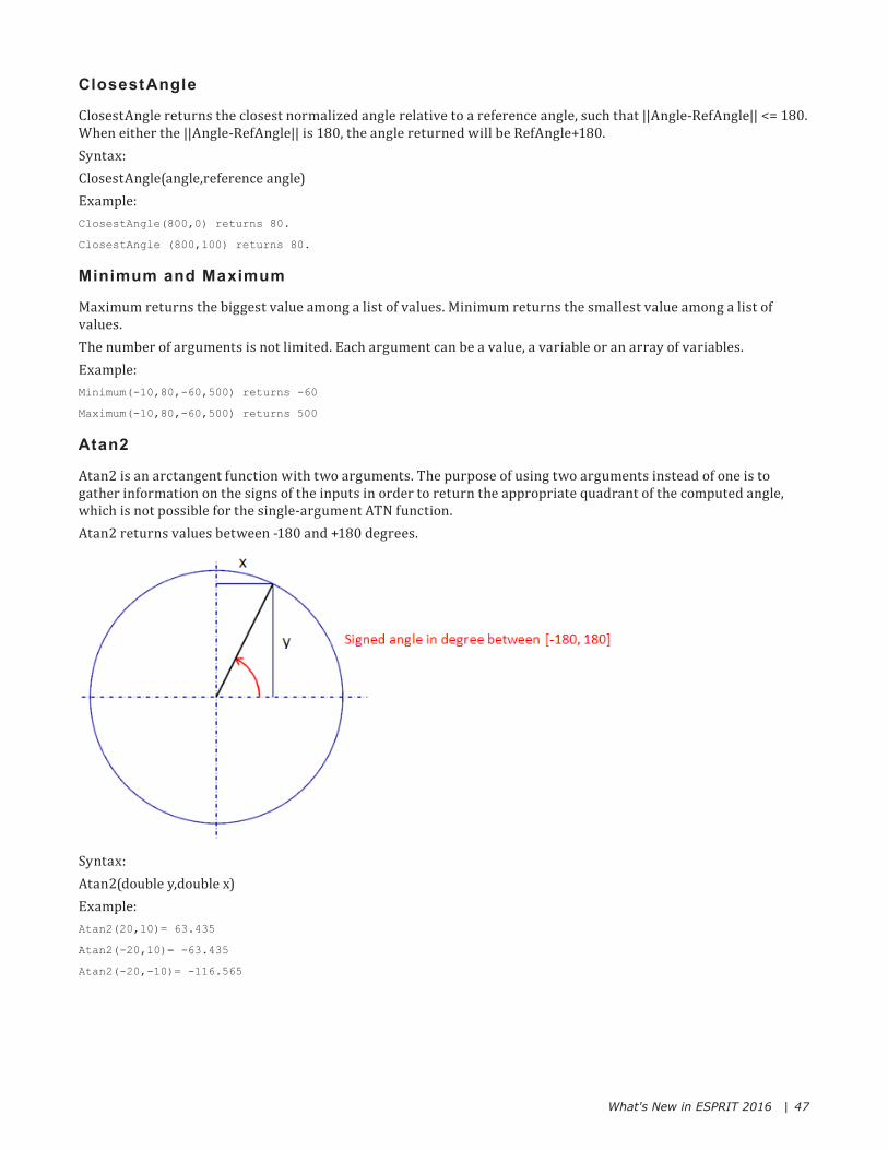
Atan2
Atan2 is an arctangent function with two arguments. The purpose of using two arguments instead of one is to gather information on the signs of the inputs in order to return the appropriate quadrant of the computed angle, which is not possible for the single-argument ATN function. Atan2 returns values between -180 and +180 degrees.
Syntax:Atan2(double y,double x)Example:Atan2(20,10)= 63.435
Atan2(-20,10)= -63.435
Atan2(-20,-10)= -116.565

What's New in ESPRIT 2016 | 48
Post Processor ConstantsThe post processor includes constants internally declared that you can use when writing logic inside the post. Below is a list of the available constants:
Constant ValuePI 3.141592653589793238463
RadianToDegrees 57.2957795130823208768
DegreeToRadians 0.01745329251994329576924
InchToMm 25.4
MmToInch 0.03937007874015748031496


![What's new and what's next in Electron & Chromium [2016]](https://static.fdocuments.us/doc/165x107/58f0606d1a28ab8f6c8b46bf/whats-new-and-whats-next-in-electron-chromium-2016.jpg)