What is fibre -...
18
You hear about fiber-optic cables whenever people talk about the telephone system, the cable TV system or the Internet. Fiber-optic lines are strands of optically pure glass as thin as a human hair that carry digital information over long distances. They are also used in medical imaging and mechanical engineering inspection. Parts of a single optical fiber We will show you how these tiny strands of glass transmit light and the fascinating way that these strands are made. What are Fiber Optics? Fiber optics (optical fibers) are long, thin strands of very pure glass about the diameter of a human hair. They are arranged in bundles called optical cables and used to transmit light signals over long distances. If you look closely at a single optical fiber, you will see that it has the following parts: • Core - Thin glass center of the fiber where the light travels • Cladding - Outer optical material surrounding the core that reflects the light back into the core
Transcript of What is fibre -...

You hear about fiber-optic cables whenever people talk about the telephone system, the cable TV system or the Internet. Fiber-optic lines are strands of optically pure glass as thin as a human hair that carry digital information over long distances. They are also used in medical imaging and mechanical engineering inspection.
Parts of a single optical fiber
We will show you how these tiny strands of glass transmit light and the fascinating way that these strands are made.
What are Fiber Optics?
Fiber optics (optical fibers) are long, thin strands of very pure glass about the diameter of a human hair. They are arranged in bundles called optical cables and used to transmit light signals over long distances. If you look closely at a single optical fiber, you will see that it has the following parts: • Core - Thin glass center of the fiber where the light travels • Cladding - Outer optical material surrounding the core that reflects the light back
into the core
• Buffer coating - Plastic coating that protects the fiber from damage and moisture
Hundreds or thousands of these optical fibers are arranged in bundles in optical cables. The bundles are protected by the cable's outer covering, called a jacket. Optical fibers come in two types: • Single-mode fibers • Multi-mode fibers See Tpub.com: Mode Theory for a good explanation. Single-mode fibers have small cores (about 3.5 x 10⁻⁴ inches or 9 microns in diameter) and transmit infrared laser light (wavelength = 1,300 to 1,550 nanometers). Multi-mode fibers have larger cores (about 2.5 x 10⁻³ inches or 62.5 microns in diameter) and transmit infrared light (wavelength = 850 to 1,300 nm) from light-emitting diodes (LEDs). Some optical fibers can be made from plastic. These fibers have a large core (0.04 inches or 1 mm diameter) and transmit visible red light (wavelength = 650 nm) from LEDs. Let's look at how an optical fiber works
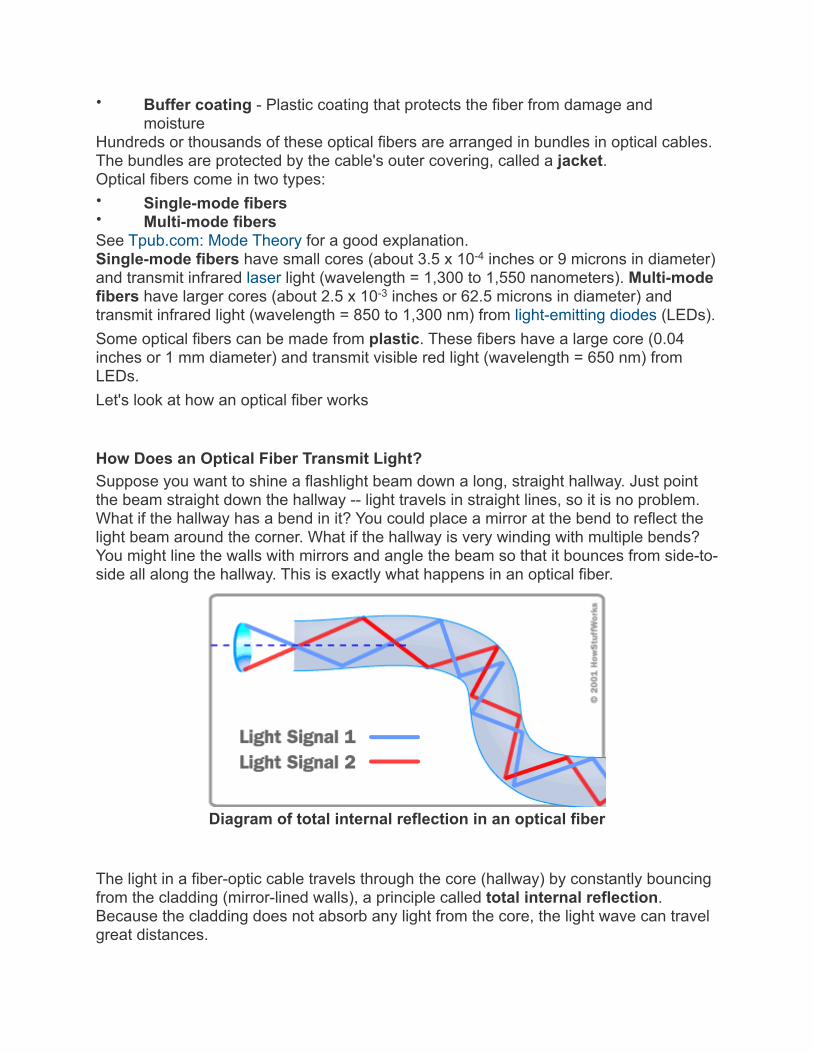
How Does an Optical Fiber Transmit Light?Suppose you want to shine a flashlight beam down a long, straight hallway. Just point the beam straight down the hallway -- light travels in straight lines, so it is no problem. What if the hallway has a bend in it? You could place a mirror at the bend to reflect the light beam around the corner. What if the hallway is very winding with multiple bends? You might line the walls with mirrors and angle the beam so that it bounces from side-to-side all along the hallway. This is exactly what happens in an optical fiber.
Diagram of total internal reflection in an optical fiber
The light in a fiber-optic cable travels through the core (hallway) by constantly bouncing from the cladding (mirror-lined walls), a principle called total internal reflection. Because the cladding does not absorb any light from the core, the light wave can travel great distances.

However, some of the light signal degrades within the fiber, mostly due to impurities in the glass. The extent that the signal degrades depends on the purity of the glass and the wavelength of the transmitted light (for example, 850 nm = 60 to 75 percent/km; 1,300 nm = 50 to 60 percent/km; 1,550 nm is greater than 50 percent/km). Some premium optical fibers show much less signal degradation -- less than 10 percent/km at 1,550 nm. A Fiber-Optic Relay SystemTo understand how optical fibers are used in communications systems, let's look at an example from a World War II movie or documentary where two naval ships in a fleet need to communicate with each other while maintaining radio silence or on stormy seas. One ship pulls up alongside the other. The captain of one ship sends a message to a sailor on deck. The sailor translates the message into Morse code (dots and dashes) and uses a signal light (floodlight with a venetian blind type shutter on it) to send the message to the other ship. A sailor on the deck of the other ship sees the Morse code message, decodes it into English and sends the message up to the captain. Now, imagine doing this when the ships are on either side of the ocean separated by thousands of miles and you have a fiber-optic communication system in place between the two ships. Fiber-optic relay systems consist of the following: • Transmitter - Produces and encodes the light signals • Optical fiber - Conducts the light signals over a distance • Optical regenerator - May be necessary to boost the light signal (for long
distances) • Optical receiver - Receives and decodes the light signals TransmitterThe transmitter is like the sailor on the deck of the sending ship. It receives and directs the optical device to turn the light "on" and "off" in the correct sequence, thereby generating a light signal. The transmitter is physically close to the optical fiber and may even have a lens to focus the light into the fiber. Lasers have more power than LEDs, but vary more with changes in temperature and are more expensive. The most common wavelengths of light signals are 850 nm, 1,300 nm, and 1,550 nm (infrared, non-visible portions of the spectrum). Optical RegeneratorAs mentioned above, some signal loss occurs when the light is transmitted through the fiber, especially over long distances (more than a half mile, or about 1 km) such as with undersea cables. Therefore, one or more optical regenerators is spliced along the cable to boost the degraded light signals. An optical regenerator consists of optical fibers with a special coating (doping). The doped portion is "pumped" with a laser. When the degraded signal comes into the doped coating, the energy from the laser allows the doped molecules to become lasers themselves. The doped molecules then emit a new, stronger light signal with the same characteristics as the incoming weak light signal. Basically, the regenerator is a laser amplifier for the incoming signal. Optical ReceiverThe optical receiver is like the sailor on the deck of the receiving ship. It takes the
incoming digital light signals, decodes them and sends the electrical signal to the other user's computer, TV or telephone (receiving ship's captain). The receiver uses a photocell or photodiode to detect the light. Advantages of Fiber OpticsWhy are fiber-optic systems revolutionizing telecommunications? Compared to conventional metal wire (copper wire), optical fibers are: • Less expensive - Several miles of optical cable can be made cheaper than
equivalent lengths of copper wire. This saves your provider (cable TV, Internet) and you money.
• Thinner - Optical fibers can be drawn to smaller diameters than copper wire. • Higher carrying capacity - Because optical fibers are thinner than copper wires,
more fibers can be bundled into a given-diameter cable than copper wires. This allows more phone lines to go over the same cable or more channels to come through the cable into your cable TV box.
• Less signal degradation - The loss of signal in optical fiber is less than in copper wire.
• Light signals - Unlike electrical signals in copper wires, light signals from one fiber do not interfere with those of other fibers in the same cable. This means clearer phone conversations or TV reception.
• Low power - Because signals in optical fibers degrade less, lower-power transmitters can be used instead of the high-voltage electrical transmitters needed for copper wires. Again, this saves your provider and you money.
• Digital signals - Optical fibers are ideally suited for carrying digital information, which is especially useful in computer networks.
• Non-flammable - Because no electricity is passed through optical fibers, there is no fire hazard.
• Lightweight - An optical cable weighs less than a comparable copper wire cable. Fiber-optic cables take up less space in the ground.
• Flexible - Because fiber optics are so flexible and can transmit and receive light, they are used in many flexible digital cameras for the following purposes:
Medical imaging - in bronchoscopes, endoscopes, laparoscopes Mechanical imaging - inspecting mechanical welds in pipes and engines (in airplanes, rockets, space shuttles, cars) Plumbing - to inspect sewer lines
Because of these advantages, you see fiber optics in many industries, most notably telecommunications and computer networks. For example, if you telephone Europe from the United States (or vice versa) and the signal is bounced off a communications satellite, you often hear an echo on the line. But with transatlantic fiber-optic cables, you have a direct connection with no echoes. How Are Optical Fibers Made?Now that we know how fiber-optic systems work and why they are useful -- how do they make them? Optical fibers are made of extremely pure optical glass. We think of a glass window as transparent, but the thicker the glass gets, the less transparent it becomes due to impurities in the glass. However, the glass in an optical fiber has far

fewer impurities than window-pane glass. One company's description of the quality of glass is as follows: If you were on top of an ocean that is miles of solid core optical fiber glass, you could see the bottom clearly. Making optical fibers requires the following steps: 1. Making a preform glass cylinder 2. Drawing the fibers from the preform 3. Testing the fibers Making the Preform BlankThe glass for the preform is made by a process called modified chemical vapor deposition (MCVD).
Image courtesy Fibercore Ltd.MCVD process for making the preform blank
•
In MCVD, oxygen is bubbled through solutions of silicon chloride (SiCl4), germanium chloride (GeCl4) and/or other chemicals. The precise mixture governs the various physical and optical properties (index of refraction, coefficient of expansion, melting point, etc.). The gas vapors are then conducted to the inside of a synthetic silica or quartz tube (cladding) in a special lathe. As the lathe turns, a torch is moved up and down the outside of the tube. The extreme heat from the torch causes two things to happen: The silicon and germanium react with oxygen, forming silicon dioxide (SiO2) and germanium dioxide (GeO2).
• The silicon dioxide and germanium dioxide deposit on the inside of the tube and fuse together to form glass.
The lathe turns continuously to make an even coating and consistent blank. The purity of the glass is maintained by using corrosion-resistant plastic in the gas delivery system
Photo courtesy Fibercore Ltd.
Lathe used in preparingthe preform blank

(valve blocks, pipes, seals) and by precisely controlling the flow and composition of the mixture. The process of making the preform blank is highly automated and takes several hours. After the preform blank cools, it is tested for quality control (index of refraction). Drawing Fibers from the Preform BlankOnce the preform blank has been tested, it gets loaded into a fiber drawing tower.
Diagram of a fiber drawing tower used to draw optical glass fibers from a preform blank
The blank gets lowered into a graphite furnace (3,452 to 3,992 degrees Fahrenheit or 1,900 to 2,200 degrees Celsius) and the tip gets melted until a molten glob falls down by gravity. As it drops, it cools and forms a thread. The operator threads the strand through a series of coating cups (buffer coatings) and ultraviolet light curing ovens onto a tractor-controlled spool. The tractor mechanism slowly pulls the fiber from the heated preform blank and is precisely controlled by using a laser micrometer to measure the diameter of the fiber and feed the information back to the tractor mechanism. Fibers are pulled from the blank at a rate of 33 to 66 ft/s (10 to 20 m/s) and the finished product is wound onto the spool. It is not uncommon for spools to contain more than 1.4 miles (2.2 km) of optical fiber. Testing the Finished Optical FiberThe finished optical fiber is tested for the following:

• Tensile strength - Must withstand 100,000 lb/in2 or more • Refractive index profile - Determine numerical aperture as well as screen for
optical defects
•
Photo courtesy CorningFinished spool of optical fiber
Fiber geometry - Core diameter, cladding dimensions and coating diameter are uniform • Attenuation - Determine the extent that light signals of various wavelengths
degrade over distance • Information carrying capacity (bandwidth) - Number of signals that can be
carried at one time (multi-mode fibers) • Chromatic dispersion - Spread of various wavelengths of light through the core
(important for bandwidth) • Operating temperature/humidity range • Temperature dependence of attenuation • Ability to conduct light underwater - Important for undersea cables Once the fibers have passed the quality control, they are sold to telephone companies, cable companies and network providers. Many companies are currently replacing their old copper-wire-based systems with new fiber-optic-based systems to improve speed, capacity and clarity.
Physics of Total Internal ReflectionWhen light passes from a medium with one index of refraction (m1) to another medium with a lower index of refraction (m2), it bends or refracts away from an imaginary line perpendicular to the surface (normal line). As the angle of the beam through m1 becomes greater with respect to the normal line, the refracted light through m2 bends further away from the line. At one particular angle (critical angle), the refracted light will not go into m2, but instead will travel along the surface between the two media (sine [critical angle] = n2/n1 where n1 and n2 are the indices of refraction [n1 is greater than n2]). If the beam through m1 is greater than the critical angle, then the refracted beam will be reflected entirely back into m1 (total internal reflection), even though m2 may be transparent! In physics, the critical angle is described with respect to the normal line. In fiber optics, the critical angle is described with respect to the parallel axis running down the middle

of the fiber. Therefore, the fiber-optic critical angle = (90 degrees - physics critical angle).
Total internal reflection in an optical fiber
In an optical fiber, the light travels through the core (m1, high index of refraction) by constantly reflecting from the cladding (m2, lower index of refraction) because the angle of the light is always greater than the critical angle. Light reflects from the cladding no matter what angle the fiber itself gets bent at, even if it's a full circle! Because the cladding does not absorb any light from the core, the light wave can travel great distances. However, some of the light signal degrades within the fiber, mostly due to impurities in the glass. The extent that the signal degrades depends upon the purity of the glass and the wavelength of the transmitted light (for example, 850 nm = 60 to 75 percent/km; 1,300 nm = 50 to 60 percent/km; 1,550 nm is greater than 50 percent/km). Some premium optical fibers show much less signal degradation -- less than 10 percent/km at 1,550 nm. For more information on fiber optics and related topics, check out the links on the next page.
Multi-mode fiber
The propaga*on of light through a mul*-‐mode op*cal fiber.
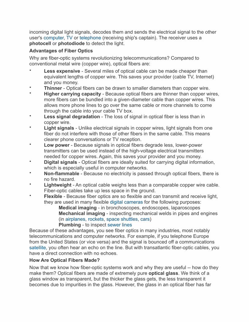
A laser bouncing down an acrylic rod, illustra*ng the total internal reflec*on of light in a mul*-‐mode op*cal fiber.
Main ar*cle: Mul*-‐mode op*cal fiber
Fiber with large core diameter (greater than 10 micrometers) may be analyzed by geometric optics. Such fiber is called multi-mode fiber, from the electromagnetic analysis (see below). In a step-index multi-mode fiber, rays of light are guided along the fiber core by total internal reflection. Rays that meet the core-cladding boundary at a high angle (measured relative to a line normal to the boundary), greater than the critical angle for this boundary, are completely reflected. The critical angle (minimum angle for total internal reflection) is determined by the difference in index of refraction between the core and cladding materials. Rays that meet the boundary at a low angle are refracted from the core into the cladding, and do not convey light and hence information along the fiber. The critical angle determines the acceptance angle of the fiber, often reported as a numerical aperture. A high numerical aperture allows light to propagate down the fiber in rays both close to the axis and at various angles, allowing efficient coupling of light into the fiber. However, this high numerical aperture increases the amount of dispersion as rays at different angles have different path lengths and therefore take different times to traverse the fiber. A low numerical aperture may therefore be desirable.
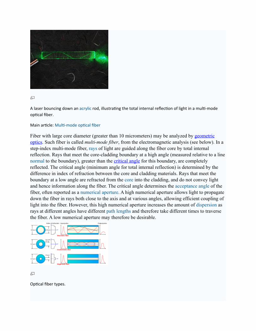
Op*cal fiber types.
In graded-index fiber, the index of refraction in the core decreases continuously between the axis and the cladding. This causes light rays to bend smoothly as they approach the cladding, rather than reflecting abruptly from the core-cladding boundary. The resulting curved paths reduce multi-path dispersion because high angle rays pass more through the lower-index periphery of the core, rather than the high-index center. The index profile is chosen to minimize the difference in axial propagation speeds of the various rays in the fiber. This ideal index profile is very close to a parabolic relationship between the index and the distance from the axis.
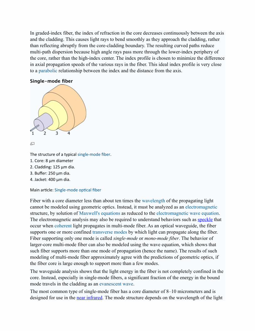
Single-mode fiber
The structure of a typical single-‐mode fiber.1. Core: 8 µm diameter2. Cladding: 125 µm dia.3. Buffer: 250 µm dia.4. Jacket: 400 µm dia.
Main ar*cle: Single-‐mode op*cal fiber
Fiber with a core diameter less than about ten times the wavelength of the propagating light cannot be modeled using geometric optics. Instead, it must be analyzed as an electromagnetic structure, by solution of Maxwell's equations as reduced to the electromagnetic wave equation. The electromagnetic analysis may also be required to understand behaviors such as speckle that occur when coherent light propagates in multi-mode fiber. As an optical waveguide, the fiber supports one or more confined transverse modes by which light can propagate along the fiber. Fiber supporting only one mode is called single-mode or mono-mode fiber. The behavior of larger-core multi-mode fiber can also be modeled using the wave equation, which shows that such fiber supports more than one mode of propagation (hence the name). The results of such modeling of multi-mode fiber approximately agree with the predictions of geometric optics, if the fiber core is large enough to support more than a few modes.The waveguide analysis shows that the light energy in the fiber is not completely confined in the core. Instead, especially in single-mode fibers, a significant fraction of the energy in the bound mode travels in the cladding as an evanescent wave.The most common type of single-mode fiber has a core diameter of 8–10 micrometers and is designed for use in the near infrared. The mode structure depends on the wavelength of the light
used, so that this fiber actually supports a small number of additional modes at visible wavelengths. Multi-mode fiber, by comparison, is manufactured with core diameters as small as 50 micrometers and as large as hundreds of micrometres. The normalized frequency V for this fiber should be less than the first zero of the Bessel function J0 (approximately 2.405).
Special-purpose fiberSome special-purpose optical fiber is constructed with a non-cylindrical core and/or cladding layer, usually with an elliptical or rectangular cross-section. These include polarization-maintaining fiber and fiber designed to suppress whispering gallery mode propagation.Photonic crystal fiber is made with a regular pattern of index variation (often in the form of cylindrical holes that run along the length of the fiber). Such fiber uses diffraction effects instead of or in addition to total internal reflection, to confine light to the fiber's core. The properties of the fiber can be tailored to a wide variety of applications.
Mechanisms of attenuation
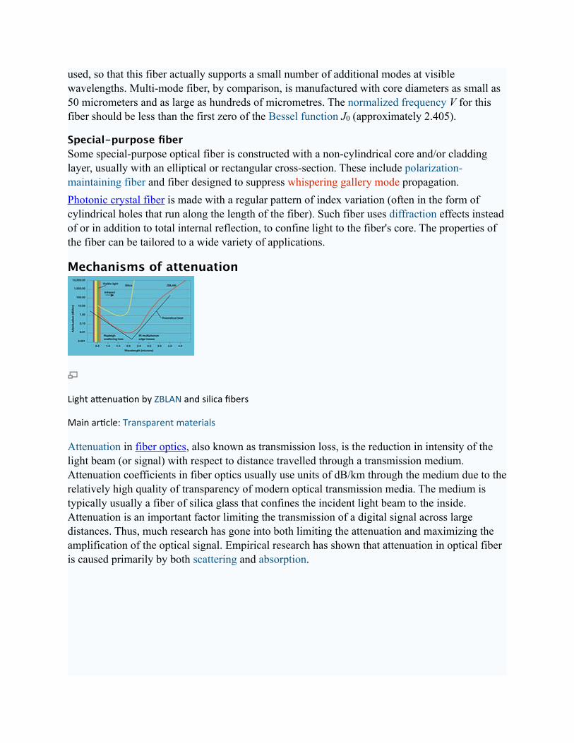
Light aPenua*on by ZBLAN and silica fibers
Main ar*cle: Transparent materials
Attenuation in fiber optics, also known as transmission loss, is the reduction in intensity of the light beam (or signal) with respect to distance travelled through a transmission medium. Attenuation coefficients in fiber optics usually use units of dB/km through the medium due to the relatively high quality of transparency of modern optical transmission media. The medium is typically usually a fiber of silica glass that confines the incident light beam to the inside. Attenuation is an important factor limiting the transmission of a digital signal across large distances. Thus, much research has gone into both limiting the attenuation and maximizing the amplification of the optical signal. Empirical research has shown that attenuation in optical fiber is caused primarily by both scattering and absorption.

Light scattering
Specular reflec*on
Diffuse reflec*on
The propagation of light through the core an optical fiber is based on total internal reflection of the lightwave. Rough and irregular surfaces, even at the molecular level, can cause light rays to be reflected in random directions. This is called diffuse reflection or scattering, and it is typically characterized by wide variety of reflection angles.Light scattering depends on the wavelength of the light being scattered. Thus, limits to spatial scales of visibility arise, depending on the frequency of the incident lightwave and the physical dimension (or spatial scale) of the scattering center, which is typically in the form of some specific microstructural feature. Since visible light has a wavelength of the order of one micron (one millionth of a meter) scattering centers will have dimensions on a similar spatial scale.Thus, attenuation results from the incoherent scattering of light at internal surfaces and interfaces. In (poly)crystalline materials such as metals and ceramics, in addition to pores, most of the internal surfaces or interfaces are in the form of grain boundaries that separate tiny regions of crystalline order. It has recently been shown that when the size of the scattering center (or grain boundary) is reduced below the size of the wavelength of the light being scattered, the scattering no longer occurs to any significant extent. This phenomenon has given rise to the production of transparent ceramic materials.
Similarly, the scattering of light in optical quality glass fiber is caused by molecular level irregularities (compositional fluctuations) in the glass structure. Indeed, one emerging school of thought is that a glass is simply the limiting case of a polycrystalline solid. Within this framework, "domains" exhibiting various degrees of short-range order become the building blocks of both metals and alloys, as well as glasses and ceramics. Distributed both between and within these domains are micro-structural defects which will provide the most ideal locations for the occurrence of light scattering. This same phenomenon is seen as one of the limiting factors in the transparency of IR missile domes.[16]
At high optical powers, scattering can also be caused by nonlinear optical processes in the fiber.[17][18]
See also: Physics of glass
UV-Vis-IR absorptionIn addition to light scattering, attenuation or signal loss can also occur due to selective absorption of specific wavelengths, in a manner similar to that responsible for the appearance of color. Primary material considerations include both electrons and molecules as follows:1) At the electronic level, it depends on whether the electron orbitals are spaced (or "quantized") such that they can absorb a quantum of light (or photon) of a specific wavelength or frequency in the ultraviolet (UV) or visible ranges. This is what gives rise to color.2) At the atomic or molecular level, it depends on the frequencies of atomic or molecular vibrations or chemical bonds, how close-packed its atoms or molecules are, and whether or not the atoms or molecules exhibit long-range order. These factors will determine the capacity of the material transmitting longer wavelengths in the infrared (IR), far IR, radio and microwave ranges.The design of any optically transparent device requires the selection of materials based upon knowledge of its properties and limitations. The lattice absorption characteristics observed at the lower frequency regions (mid IR to far-infrared wavelength range) define the long-wavelength transparency limit of the material. They are the result of the interactive coupling between the motions of thermally induced vibrations of the constituent atoms and molecules of the solid lattice and the incident light wave radiation. Hence, all materials are bounded by limiting regions of absorption caused by atomic and molecular vibrations (bond-stretching)in the far-infrared (>10 µm).

Normal modes of vibra*on in a crystalline solid.
Thus, multi-phonon absorption occurs when two or more phonons simultaneously interact to produce electric dipole moments with which the incident radiation may couple. These dipoles can absorb energy from the incident radiation, reaching a maximum coupling with the radiation when the frequency is equal to the fundamental vibrational mode of the molecular dipole (e.g. Si-O bond) in the far-infrared, or one of its harmonics.The selective absorption of infrared (IR) light by a particular material occurs because the selected frequency of the light wave matches the frequency (or an integral multiple of the frequency) at which the particles of that material vibrate. Since different atoms and molecules have different natural frequencies of vibration, they will selectively absorb different frequencies (or portions of the spectrum) of infrared (IR) light.Reflection and transmission of light waves occur because the frequencies of the light waves do not match the natural resonant frequencies of vibration of the objects. When IR light of these frequencies strike an object, the energy is either reflected or transmitted.
Optical Fiber Calculations
Enter in these first 4 parameters which describe the properties of the optical fiber. Then enter the maximum amount of light you are able to enter into the fiber. From these parameters this calculator will tell you numerous capabilities and characteristics of your fiber. In addition, the graph below shows a Gaussian estimation of where the majority of your field lies within your fiber (in the core/cladding).

Wavelength (λ): [um] (1.3-‐1.6)
Core radius (a): [um]
Index of Core* (n1):
Index of Cladding* (n2):
Maximum intensity of light (Io): [uW]
(*NOTE: n1 must be slightly larger than n2 to guide light.) (*NOTE: n1 must be slightly larger than n2 to guide light.)
Numerical Aperature (NA):
V-Number (V):
Mode Type: [Single mode: V < 2.405]
Number of Modes: [Single mode: V < 2.405]
Spot size radius (wo): [um]
Mode Field Diameter (MFD): [um]
Power at MFD: [W]

Light Profile in Optical Fiberwith above Parameters
The location where these two graphs intersect show the boundary of the Mode Field Diameter.
Equations used above:
Numerical Aperature NA = √(n12-‐n22)
V-number V = 2*π*a*NA/λ
Spot size: wo = a*(.65 +1.619*V-‐1.5+2.879*V-‐6)
Mode Field Diameter: MFD = 2*wo
Intensity at MFD: I(wo) = Io*e-‐2 = .135*Io
Bandwidth-distance productBecause the effect of dispersion increases with the length of the fiber, a fiber transmission system is often characterized by its bandwidth-distance product, often expressed in units of MHz×km. This value is a product of bandwidth and distance because there is a trade off between the bandwidth of the signal and the distance it can be carried. For example, a common multimode fiber with bandwidth-distance product of 500 MHz×km could carry a 500 MHz signal for 1 km or a 1000 MHz signal for 0.5 km.Through a combination of advances in dispersion management, wavelength-division multiplexing, and optical amplifiers, modern-day optical fibers can carry information at around 14 Terabits per second over 160 kilometers of fiber [4]. Engineers are always looking at current limitations in order to improve fiber-optic communication, and several of these restrictions are currently being researched:
DispersionFor modern glass optical fiber, the maximum transmission distance is limited not by direct material absorption but by several types of dispersion, or spreading of optical pulses as they travel along the fiber. Dispersion in optical fibers is caused by a variety of factors. Intermodal dispersion, caused by the different axial speeds of different transverse modes, limits the performance of multi-mode fiber. Because single-mode fiber supports only one transverse mode, intermodal dispersion is eliminated.In single-mode fiber performance is primarily limited by chromatic dispersion (also called group velocity dispersion), which occurs because the index of the glass varies slightly depending on the wavelength of the light, and light from real optical transmitters necessarily has nonzero spectral width (due to modulation). Polarization mode dispersion, another source of limitation, occurs because although the single-mode fiber can sustain only one transverse mode, it can carry this mode with two different polarizations, and slight imperfections or distortions in a fiber can alter the propagation velocities for the two polarizations. This phenomenon is called fiber birefringence and can be counteracted by polarization-maintaining optical fiber. Dispersion limits the bandwidth of the fiber because the spreading optical pulse limits the rate that pulses can follow one another on the fiber and still be distinguishable at the receiver.Some dispersion, notably chromatic dispersion, can be removed by a 'dispersion compensator'. This works by using a specially prepared length of fiber that has the opposite dispersion to that induced by the transmission fiber, and this sharpens the pulse so that it can be correctly decoded by the electronics.
AttenuationFiber attenuation, which necessitates the use of amplification systems, is caused by a combination of material absorption, Rayleigh scattering, Mie scattering, and connection losses. Although material absorption for pure silica is only around 0.03 dB/km (modern fiber has attenuation around 0.3 dB/km), impurities in the original optical fibers caused attenuation of about 1000 dB/km. Other forms of attenuation are caused by physical stresses to the fiber, microscopic fluctuations in density, and imperfect splicing techniques.
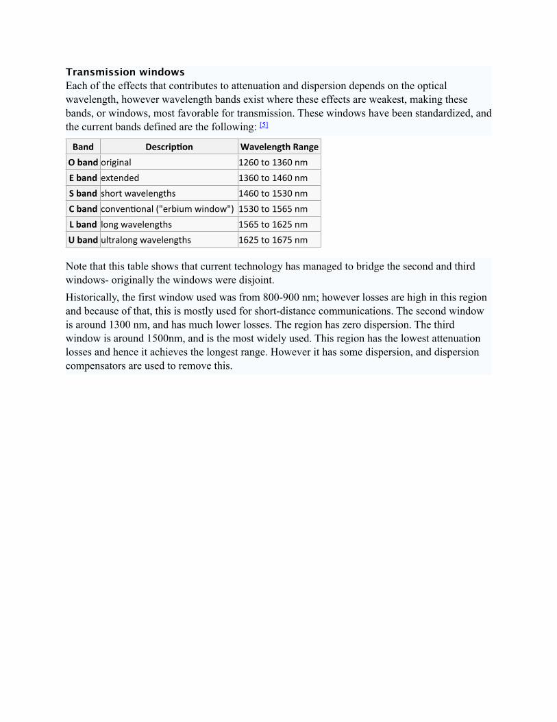
Transmission windowsEach of the effects that contributes to attenuation and dispersion depends on the optical wavelength, however wavelength bands exist where these effects are weakest, making these bands, or windows, most favorable for transmission. These windows have been standardized, and the current bands defined are the following: [5]
Band Descrip,on Wavelength RangeO band original 1260 to 1360 nmE band extended 1360 to 1460 nmS band short wavelengths 1460 to 1530 nmC band conven*onal ("erbium window") 1530 to 1565 nmL band long wavelengths 1565 to 1625 nmU band ultralong wavelengths 1625 to 1675 nm
Note that this table shows that current technology has managed to bridge the second and third windows- originally the windows were disjoint.Historically, the first window used was from 800-900 nm; however losses are high in this region and because of that, this is mostly used for short-distance communications. The second window is around 1300 nm, and has much lower losses. The region has zero dispersion. The third window is around 1500nm, and is the most widely used. This region has the lowest attenuation losses and hence it achieves the longest range. However it has some dispersion, and dispersion compensators are used to remove this.