What Are We Protecting? - AUCSC speaker files/TT08 - M'town OV Protection...Over-Voltage Protection...
34
Over-Voltage Protection for CP Systems What Are We Protecting? • Personnel (primary) • Equipment (secondary)
Transcript of What Are We Protecting? - AUCSC speaker files/TT08 - M'town OV Protection...Over-Voltage Protection...
Over-Voltage Protection for
CP Systems
What Are We Protecting?
• Personnel (primary)
• Equipment (secondary)
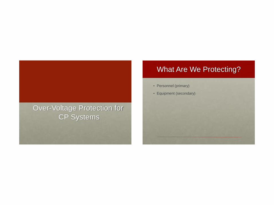
Personnel Protection:
Touch Potential
Personnel Protection:
Step Potential
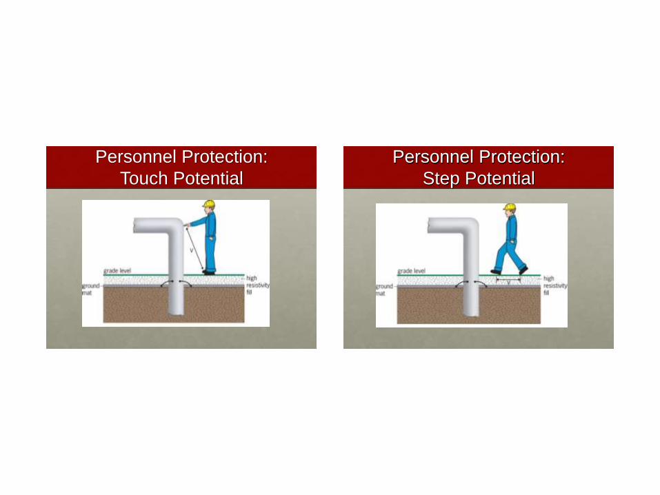
Equipment Protection
• Punctured coatings
• Breakdown of insulation
• Fuel ignition/explosion
• Equipment failure
Equipment Protection
Example
From What Voltage
Sources?
• Lightning (most difficult)
• AC power system faults*
• Induced voltage*
• *If induced voltage is present, AC faults are then also
of concern
Over-Voltage Protection Goal
• Minimize voltage difference between points of
concern:
• Worker contact points
• Across insulated joints
• From exposed pipelines to ground
• Across electrical equipment insulation
• Different considerations apply for:
• Lightning
• AC faults
• Induced voltage
Over-Voltage Protection Goal Lightning Protection:
Primary Considerations
• Clamping voltage (CCV) of protective device
• Voltage drop in connecting leads
• Inductive voltage (VIV)
• Resistive voltage (VRV)
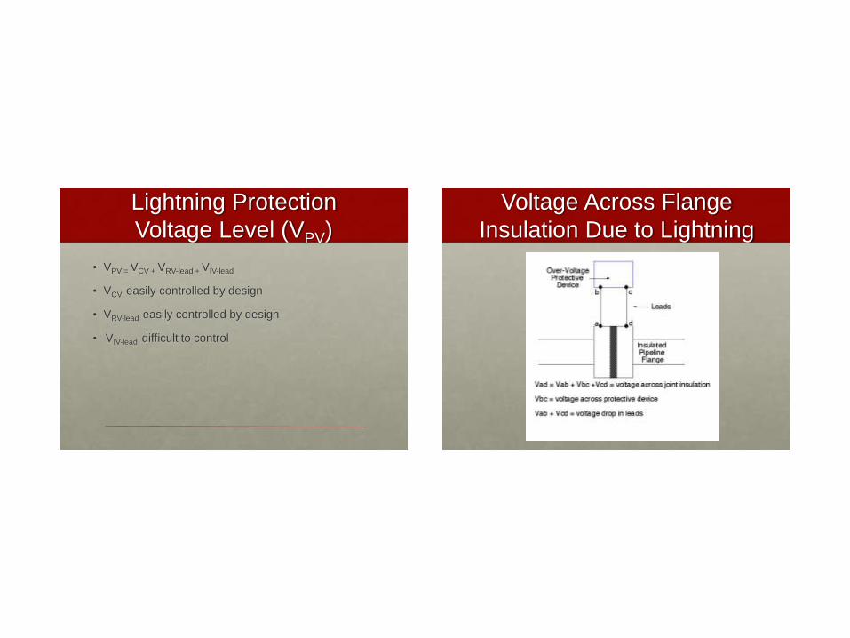
Lightning Protection
Voltage Level (VPV)
• VPV = VCV + VRV-lead + VIV-lead
• VCV easily controlled by design
• VRV-lead easily controlled by design
• VIV-lead difficult to control
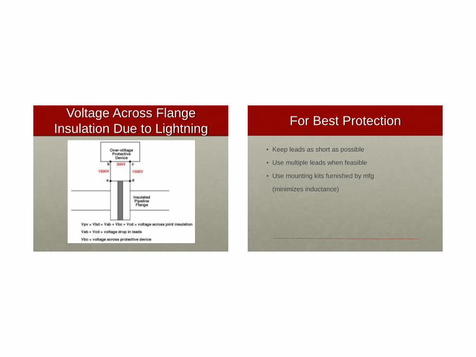
Voltage Across Flange
Insulation Due to Lightning
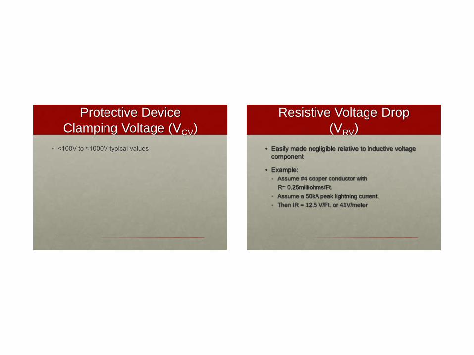
Protective Device
Clamping Voltage (VCV)
• <100V to ≈1000V typical values
Resistive Voltage Drop
(VRV)
• Easily made negligible relative to inductive voltage
component
• Example:
• Assume #4 copper conductor with
R= 0.25milliohms/Ft.
• Assume a 50kA peak lightning current.
• Then IR = 12.5 V/Ft. or 41V/meter
Inductive Voltage Drop
(VIV)
• VIV = L (di/dt) where:
• L = lead inductance, µH/ft
• di/dt = rate of change of current, amps/microsecond
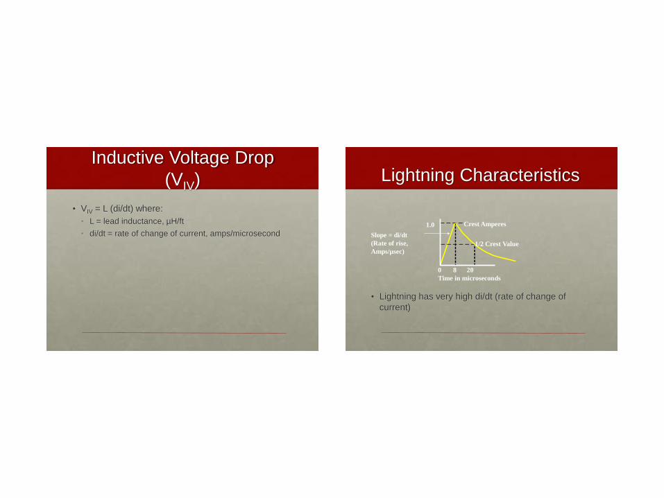
Lightning Characteristics
• Lightning has very high di/dt (rate of change of
current)
0 8 20
Time in microseconds
Slope = di/dt
(Rate of rise,
Amps/µsec)
Crest Amperes 1.0
1/2 Crest Value
Typical (VIV) Parameters
• Lead inductance (L): 0.2µH/ft. typical
• Typical di/dt
• 15,000A/µ-sec indirect lightning strike
• 150,000A/µ-sec direct lightning strike
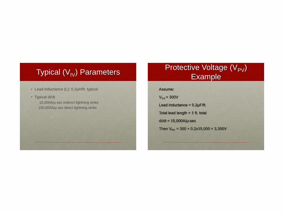
Protective Voltage (VPV)
Example
Assume:
VCV = 300V
Lead inductance = 0.2µF/ft.
Total lead length = 1 ft. total
di/dt = 15,000A/µ-sec
Then VPV = 300 + 0.2x15,000 = 3,300V
Voltage Across Flange
Insulation Due to Lightning For Best Protection
• Keep leads as short as possible
• Use multiple leads when feasible
• Use mounting kits furnished by mfg
(minimizes inductance)
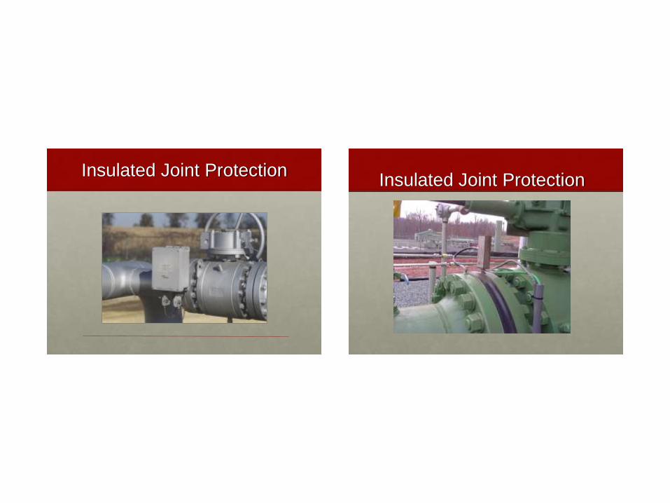
Insulated Joint Protection Insulated Joint Protection
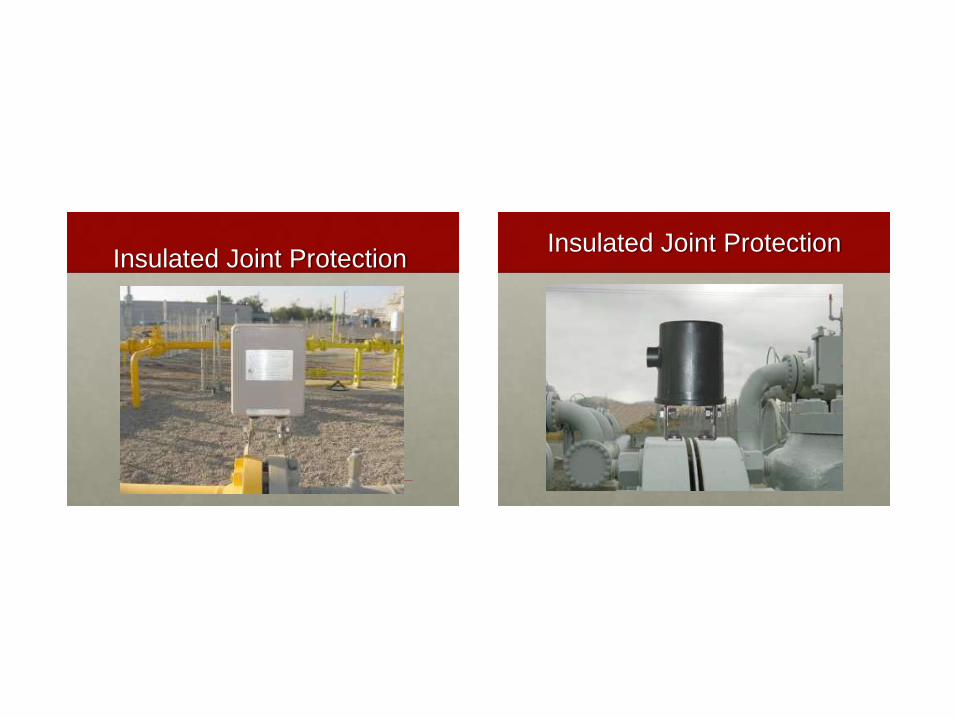
Insulated Joint Protection Insulated Joint Protection
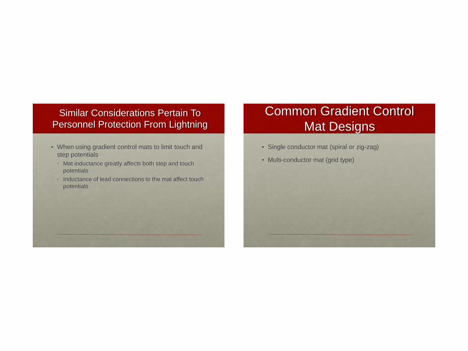
Similar Considerations Pertain To
Personnel Protection From Lightning
• When using gradient control mats to limit touch and
step potentials
• Mat inductance greatly affects both step and touch
potentials
• Inductance of lead connections to the mat affect touch
potentials
Common Gradient Control
Mat Designs
• Single conductor mat (spiral or zig-zag)
• Multi-conductor mat (grid type)
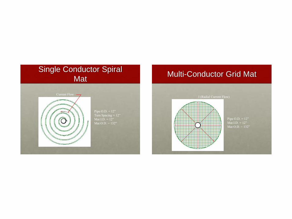
Single Conductor Spiral
Mat
Pipe O.D. = 12”
Turn Spacing = 12”
Mat I.D. = 12”
Mat O.D. = 132”
Current Flow
Multi-Conductor Grid Mat
I (Radial Current Flow)
Pipe O.D. = 12”
Mat I.D. = 12”
Mat O.D. = 132”
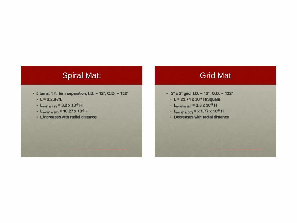
Spiral Mat:
• 5 turns, 1 ft. turn separation, I.D. = 12”, O.D. = 132”
• L = 0.2µF/ft.
• L(r=6” to 18”) = 3.2 x 10⁻⁶ H
• L(r=18” to 30”) = 10.27 x 10⁻⁶ H
• L increases with radial distance
Grid Mat
• 2” x 2” grid, I.D. = 12”, O.D. = 132”
• L = 21.74 x 10⁻⁹ H/Square
• L(r= 6” to 18”) = 3.8 x 10⁻⁹ H
• L(r= 18” to 30”) = x 1.77 x 10⁻⁹ H
• Decreases with radial distance
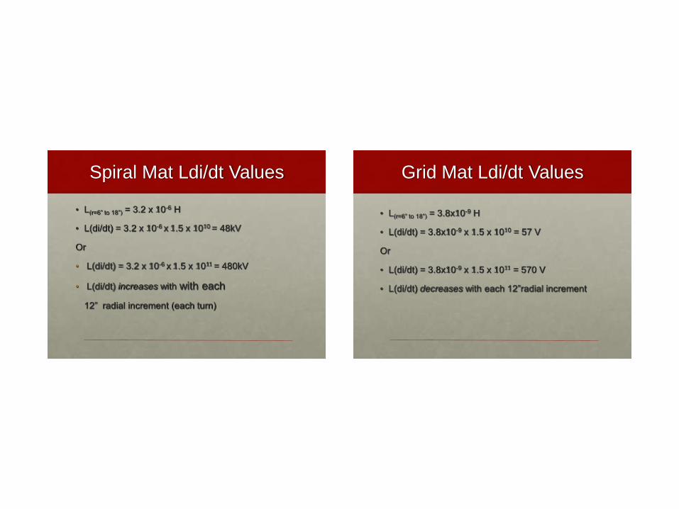
Spiral Mat Ldi/dt Values
• L(r=6” to 18”) = 3.2 x 10⁻⁶ H
• L(di/dt) = 3.2 x 10-6 x 1.5 x 1010 = 48kV
Or
• L(di/dt) = 3.2 x 10-6 x 1.5 x 1011 = 480kV
• L(di/dt) increases with with each
12” radial increment (each turn)
Grid Mat Ldi/dt Values
• L(r=6” to 18”) = 3.8x10⁻⁹ H
• L(di/dt) = 3.8x10-9 x 1.5 x 1010 = 57 V
Or
• L(di/dt) = 3.8x10-9 x 1.5 x 1011 = 570 V
• L(di/dt) decreases with each 12”radial increment
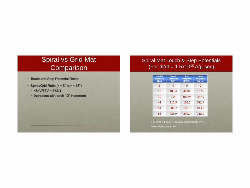
Spiral vs Grid Mat
Comparison
• Touch and Step Potential Ratios
• Spiral/Grid Ratio (r = 6” to r = 18”)
• 48kV/57V = 842:1
• Increases with each 12” increment
Spiral Mat Touch & Step Potentials
(For di/dt = 1.5x10¹⁰ A/µ-sec)
Radial Distance
(In.)
Touch Potential
(kV)
Step Potential (kV/ft)
Step Potential (kV/m)
6 0 0 0
18 48.04 48.04 157.6
30 154 105.96 347.5
42 310.5 156.3 512.7
54 506.7 196.3 643.9
66 725.9 219.9 718.9
For di/dt = 1.5x10¹¹, multiply all potentials by 10
Note: Potentials in kV
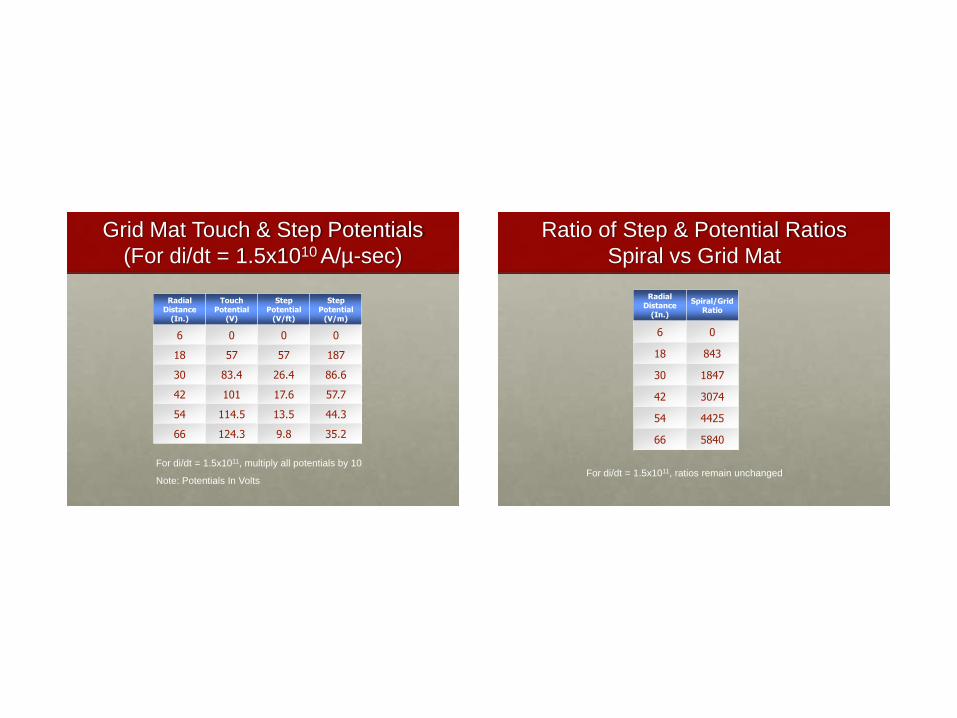
Grid Mat Touch & Step Potentials
(For di/dt = 1.5x10¹⁰ A/µ-sec)
Radial Distance
(In.)
Touch Potential
(V)
Step Potential
(V/ft)
Step Potential
(V/m)
6 0 0 0
18 57 57 187
30 83.4 26.4 86.6
42 101 17.6 57.7
54 114.5 13.5 44.3
66 124.3 9.8 35.2
For di/dt = 1.5x10¹¹, multiply all potentials by 10
Note: Potentials In Volts
Ratio of Step & Potential Ratios
Spiral vs Grid Mat
Radial Distance
(In.)
Spiral/Grid Ratio
6 0
18 843
30 1847
42 3074
54 4425
66 5840
For di/dt = 1.5x10¹¹, ratios remain unchanged
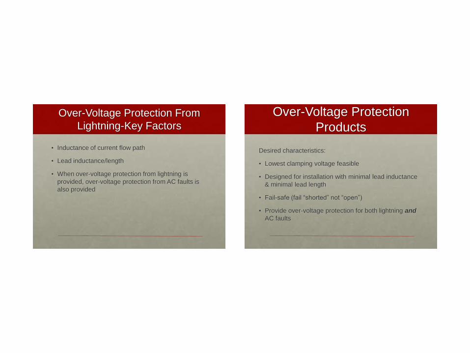
Over-Voltage Protection From
Lightning-Key Factors
• Inductance of current flow path
• Lead inductance/length
• When over-voltage protection from lightning is
provided, over-voltage protection from AC faults is
also provided
Over-Voltage Protection
Products
Desired characteristics:
• Lowest clamping voltage feasible
• Designed for installation with minimal lead inductance
& minimal lead length
• Fail-safe (fail “shorted” not “open”)
• Provide over-voltage protection for both lightning and
AC faults
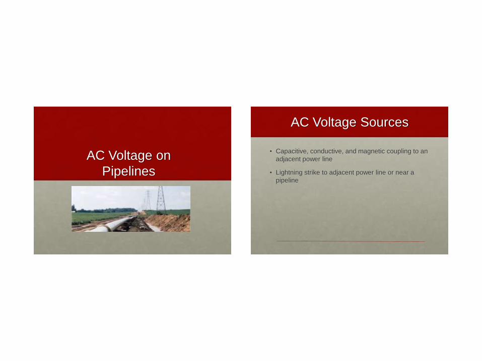
AC Voltage on
Pipelines
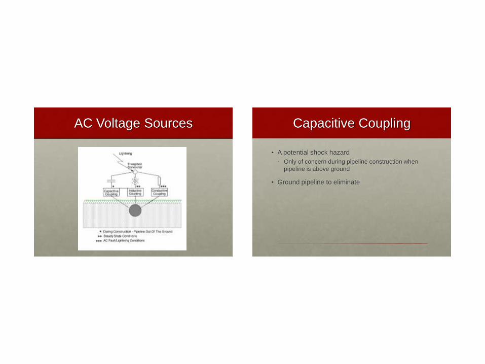
AC Voltage Sources
• Capacitive, conductive, and magnetic coupling to an
adjacent power line
• Lightning strike to adjacent power line or near a
pipeline
AC Voltage Sources Capacitive Coupling
• A potential shock hazard
• Only of concern during pipeline construction when
pipeline is above ground
• Ground pipeline to eliminate
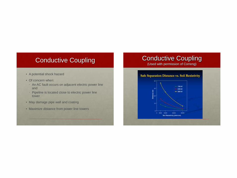
Conductive Coupling
• A potential shock hazard
• Of concern when:
• An AC fault occurs on adjacent electric power line and
• Pipeline is located close to electric power line tower
• May damage pipe wall and coating
• Maximize distance from power line towers
Conductive Coupling (Used with permission of Correng)
Magnetic Coupling
• Primary source of what is normally considered
“induced voltage”
• A potential shock hazard
• Readily mitigated
• May also cause AC corrosion of pipeline
Lightning Strike To Power
Line Adjacent to A Pipeline
• A potential shock hazard
• Due to significant rise in earth potential transferred to
adjacent pipeline
• Can readily over-stress (damage) pipeline coatings,
joint insulation, etc.
• More difficult to mitigate
Magnetically Induced
Voltage
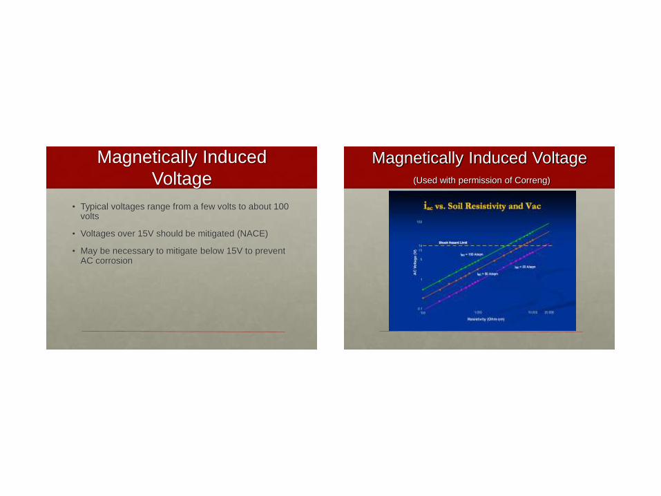
• Typical voltages range from a few volts to about 100 volts
• Voltages over 15V should be mitigated (NACE)
• May be necessary to mitigate below 15V to prevent AC corrosion
Magnetically Induced Voltage
(Used with permission of Correng)
Magnetically Induced
Voltage
Key Factors
• Proximity to power lines
• Power line loading (current magnitude)
• Quality of pipeline coating
Why Mitigate Induced
Voltage?
• To protect personnel from electric shock
• To prevent damage to pipelines, coatings, and other
pipeline equipment
• To prevent AC corrosion
Mitigation Techniques
• Spot mitigation
• Continuous mitigation
• Both approaches require a grounding system
• Depending on grounding system material:
May be direct connected to pipeline
or
Decoupled from pipeline
Spot Mitigation
• Used to reduce pipeline potentials at accessible
locations (e.g. valve sites)
• Less costly than continuous mitigation
• Grounding system may consist of:
• Magnesium or zinc, direct bonded or decoupled
• Pipeline casings, copper, etc., must be decoupled
• Gradient control mats, direct bonded or decoupled
depending on material
Continuous Mitigation
• Used to reduce pipeline potentials at all locations
• Limits voltage stress on coatings to safe levels
(primary advantage)
• Requires a continuous grounding system (typically
zinc ribbon or copper)
• Design requires specialized software
Considerations: Direct Bonded vs
Decoupled Grounding System
• Ability to take instant-off pipeline potential readings
• Decoupled-may required a “delayed-off” measurement or use of coupons
• Ability to achieve desired CP
• Stray DC current
• Mitigation costs
Mitigating Induced AC
Using A Decoupler
• A commonly asked question:
How can a decoupler with a 2V or 3V blocking
voltage be used with 30Vac on a pipeline?
Example: Pipeline with
Induced AC Voltage
• Open-circuit induced AC on a pipeline = 30 volts
• Short-circuit current = 10 amperes (to mitigation grounding system)
• Given the above, then the circuit impedance is 30V/10A =or 3 Ohms
• What is the effect of connecting the pipeline to the grounding system through a decoupler?
Example: Pipeline with Induced
AC Voltage - continued
• Typical decoupler ac impedance Xc: Xc = 0.01 ohms Because the device impedance is insignificant compared to the 3 Ohm circuit impedance, the current to ground remains ≈ 10 amps
• V(pipeline-to-grounding system) = I . Xc
• I . Xc = 10 . 0.01 = 0.1 volts
• Result: Induced AC reduced from 30V to 0.1V with respect to grounding system (well below decoupler blocking level). Will be higher to adjacent earth.
Mitigating Induced AC
• Example applies to either spot or continuous mitigation
• A decoupler provides the greatest flexibility with any mitigation method
but
• May required an alternate procedure* to determine true polarized pipe potentials
* A delayed “off” measurement or use of coupons may be required
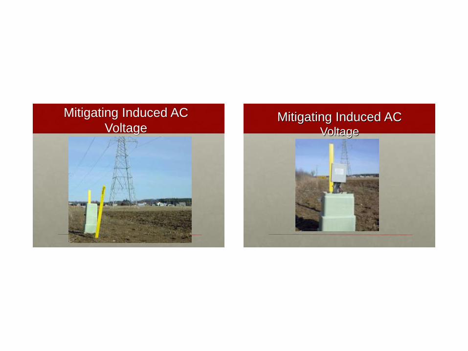
Mitigating Induced AC
Voltage
Mitigating Induced AC Voltage
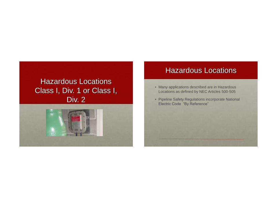
Hazardous Locations
Class I, Div. 1 or Class I,
Div. 2
Hazardous Locations
• Many applications described are in Hazardous
Locations as defined by NEC Articles 500-505
• Pipeline Safety Regulations incorporate National
Electric Code “By Reference”
Pipeline Safety Regulations
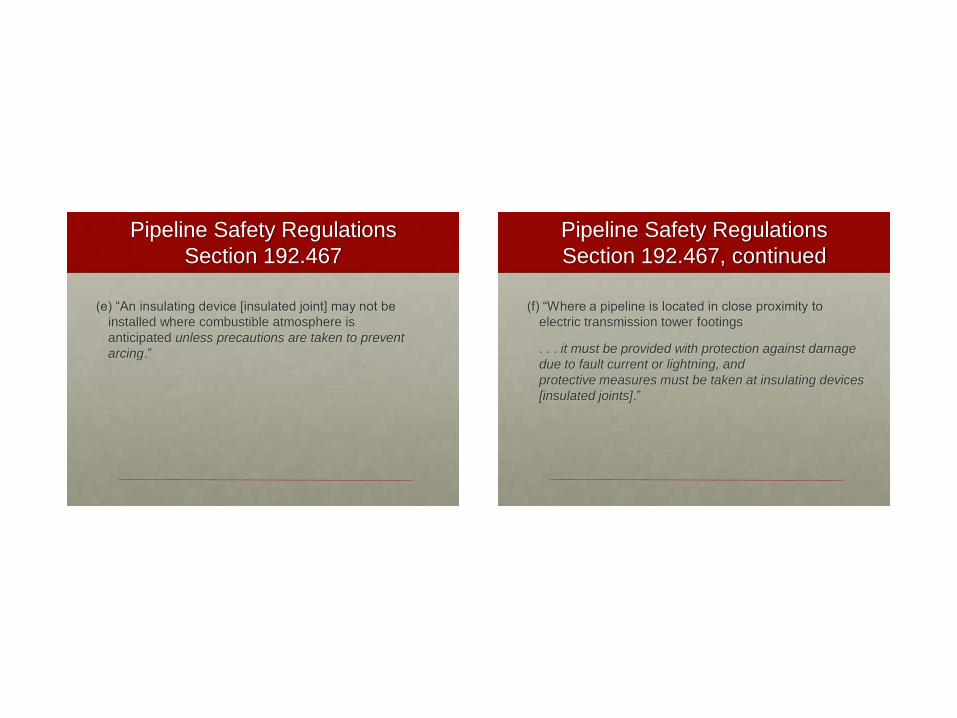
Section 192.467
(e) “An insulating device [insulated joint] may not be
installed where combustible atmosphere is
anticipated unless precautions are taken to prevent
arcing.”
Pipeline Safety Regulations
Section 192.467, continued
(f) “Where a pipeline is located in close proximity to
electric transmission tower footings
. . . it must be provided with protection against damage
due to fault current or lightning, and
protective measures must be taken at insulating devices
[insulated joints].”
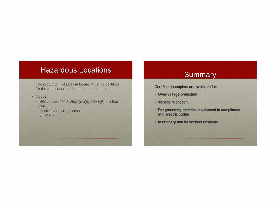
Hazardous Locations
The products [not just enclosure] must be certified
for the application and installation location
• Codes:
• NEC Articles 250.2, 250(4)(A)(5), 250-6(E) and 500-
505
• Pipeline Safety Regulations
§ 192.467
Summary
Certified decouplers are available for:
• Over-voltage protection
• Voltage mitigation
• For grounding electrical equipment in compliance
with electric codes
• In ordinary and hazardous locations
Conclusion
• Products are available or can be tailored for most
applications
• Guidelines available for product application and
model/rating selection
Henry Tachick
Dairyland Electrical Industries
P.O. Box 187
Stoughton, WI 53589
Phone: 608-877-9900
Fax: 608-877-9920
Email: [email protected]
Internet: www.dairyland.com