Executive thinking on payments: disconnects and opportunities

What are PV Systems (and Disconnects) in the 2017 NEC?
Presented by:
Bill Brooks
2019 AEE Solar Dealer Conference

2017 NEC Statistics for Article 690
Whole article was reduced from 11,000 words to about 8,000 words.
Rapid shutdown increased from 133 words to over 1100 words. Dc loads, stand-alone systems (ac loads), and battery storage
systems have historically been considered part of Article 690. With the advent of a whole new articles on energy storage systems [Article 706], stand-alone systems [Article 710], microgrids [new Part IV of Article 705], and dc microgrids [Article 712]—all these sections were removed from 690.
Interactive system
Inverter output circuit
Interact ive Inverter
Elect ric product ion and
dist ribut ion network
PV system disconnect
PV power source
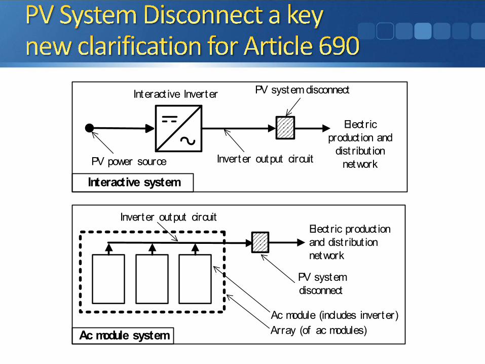
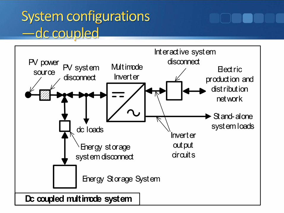
Mult imode Inverter
Elect ric product ion and
dist ribut ion network
Interact ive system disconnectPV power
source PV system disconnect
Ac module systemAc module (includes inverter)Array (of ac modules)
Inverter output circuitElect ric product ion and dist ribut ion network
PV system disconnect

Mult imode Inverter
Energy storage system disconnect
dc loads
Energy Storage System
Dc coupled multimode system
Inverter output circuits
Elect ric product ion and
dist ribut ion network
Interact ive system disconnectPV power
source PV system disconnect
Interact ive Inverter Inverter output circuit
PV system disconnect
PV power source
c odue systec odu e ( c udes e te )
ay (o ac odu es)
syste dsco ect
Stand-alonesystem loads
e gy sto age syste dsco ect
e gy Sto age Syste
c couped ut ode syste
c cuts
Ac coupled multimode system
Energy storage system disconnect
Energy StorageSystem
Mult imode Inverter
Interact ive Inverter Inverter output circuit
PV system disconnect
PV power source
Interact ive system disconnect
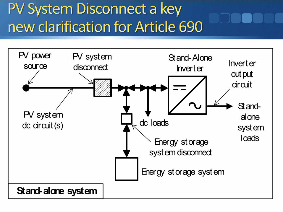
Stand-Alone Inverter
Inverter output circuit
PV power source
PV system disconnect
Elect ric product ion and dist ribut ion
network
Stand-alonesystem loads
Notes:
(1) These diagrams are intended to be a means of ident if icat ion for PV sys connect ions.
(2) The PV system disconnect in these diagrams separates the PV system
c couped ut ode syste
e gy sto age syste dsco ect
te act e syste dsco ect
Stand-alone system
Stand-Alone Inverter
Energy storage system disconnect
dc loads
Energy storage system
Inverter output circuit
Stand-alone
system loads
PV power source
PV system disconnect
a d dst but o
et o
PV system dc circuit (s)

Functional Grounded PV System.A PV system that has an electrical reference to ground that is not solidly grounded.
Informational Note: A functional grounded PV system is often connected to ground is often through a fuse, circuit breaker, resistance device, non-isolated grounded ac circuit, or electronic means that is part of a listed ground-fault protection system. Conductors in these systems that are normally at ground potential may have voltage to ground during fault conditions.

Installing Non-Isolated Inverters on PV Arrays Without Photovoltaic Wire
Presented by:
Bill Brooks, CMP 4

9

The requirements for the dc side of a PV system have been unified. Functionally grounded or ungrounded systems have same requirements. • 1) only one overcurrent device required per circuit
(previously only allowed on grounded systems) [690.9(C)]; • 2) disconnecting means in both dc legs to disconnect
equipment or a dc PV system (previous requirement for ungrounded PV systems) [690.15];
• 3) single-conductor cable in PV array can be either USE-2 or PV Wire (previously PV Wire required on modules and home runs for ungrounded PV systems) [690.31(C)(1)];
• 4) ground-fault detection details covered by listed equipment (much of detail removed from NEC) [690.41(B)].
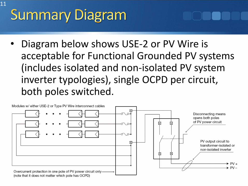
• Diagram below shows USE-2 or PV Wire is acceptable for Functional Grounded PV systems (includes isolated and non-isolated PV system inverter typologies), single OCPD per circuit, both poles switched.
11

The 2014 NEC saw a subtle but significant change related to arc-fault detection. The words “on buildings” were removed from the 2014 NEC essentially requiring that all PV systems operating above 80 volts have arc-fault protection.
Unfortunately, the standard now only covers products operating at currents up to 40 amps, so it is difficult, if not impossible to find arc-fault detectors for 200-amp to 400-amp PV output circuits.
The 2017 NEC recognized this problem and provides for an exemption from arc-fault detectors on large PV output circuits provided those circuits are not on buildings and the circuits are either underground or in metallic raceways or enclosures.
(A) Location.The PV system disconnecting means shall be installed at a readily accessible location.
Informational Note: PV systems installed in accordance with 690.12 address the concerns related to live energized conductors entering a building.

• Removed all of 690.16, 690.17, and 690.18 and placed the necessary requirements in 690.13 and 690.15.
• Introduce “Isolating Devices” to 690. • Disconnects must disconnect both positive
and negative conductors on the dc side of the PV system.

• Section completely replaced
• “(A) Buildings or Structures Supporting a PV Array. A building or structure supporting a PV array shall have a grounding electrode system installed in accordance with Part III of Article 250.

• “PV array equipment grounding conductors shall be connected to the grounding electrode system of the building or structure supporting the PV array in accordance with Part VII of Article 250. This connection shall be in addition to any other equipment grounding conductor requirements in 690.43(C). The PV array equipment grounding conductors shall be sized in accordance with 690.45.
• For PV systems that are not solidly grounded, the
• For PV systems that are not solidly grounded, the equipment grounding conductor for the output of the PV system, connected to associated distribution equipment, shall be permitted to be the connection to ground for ground-fault protection and equipment grounding of the PV array.”

• Old 690.47(D) lives on as 690.47(B) in permissive language (allowed—NOT required)
• “Grounding electrodes shall be permitted to be installed in accordance with 250.52 and 250.54 at the location of ground- and roof-mounted photovoltaic arrays….”
• Hopefully removed for good in 2020 NEC. 2017 690.47(A) covers initial intent of 2008 proposal.
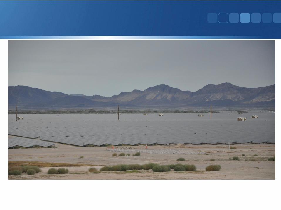
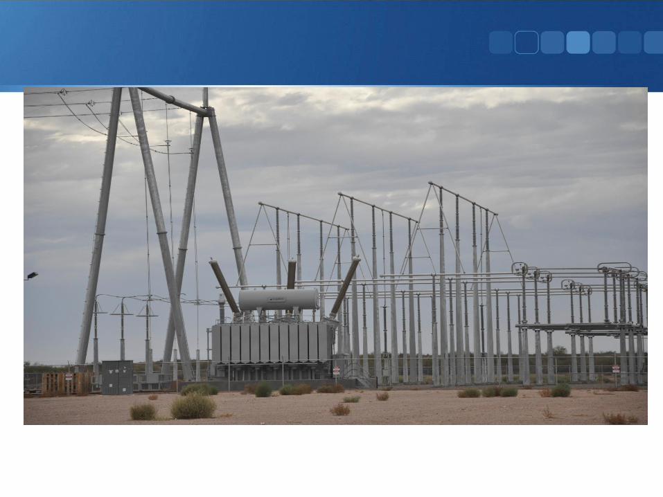
691.1 Scope. This article covers the installation of large-scale PV electric supply stations with a generating capacity of no less than 5,000 kW, and not under exclusive utility control.
Informational Note No. 1: Facilities covered by this article have specific design and safety features unique to large-scale PV facilities and are operated for the sole purpose of providing electric supply to a system operated by a regulated utility for the transfer of electric energy.
Informational Note No.2: Section 90.2(B)(5) includes information about utility-owned properties not covered under this Code. For additional information on electric supply stations, see ANSI/IEEE C2-2012, National Electrical Safety Code.
Large-scale PV electric supply stations shall be accessible only to authorized personnel and comply with the following:
(1) Electrical circuits and equipment shall be maintained and operated only by qualified personnel.
Informational Note: Refer to NFPA 70E-2015, Standard for Electrical Safety in the Workplace, for electrical safety requirements.

• (2) Access to PV electric supply stations is restricted by fencing or other adequate means in accordance with 110.31. Field- applied hazard markings shall be applied in accordance with 110.21(B).
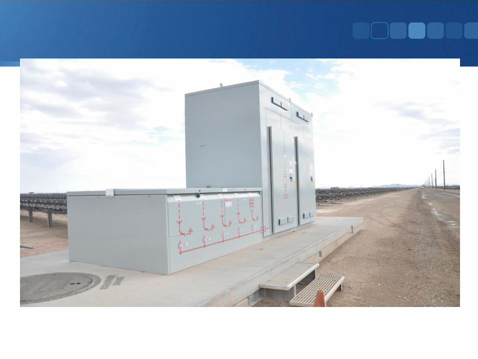
• (3) The connection between the PV electric supply station and the system operated by a utility for the transfer of electrical energy shall be through medium- or high-voltage switch gear, substation, switch yard, or similar methods whose sole purpose shall be to safely and effectively interconnect the two systems.
• (4) The electrical loads within the supply station are only used to power auxiliary equipment for the generation of the PV power.
• (5) Large-scale PV electric supply stations shall not be installed on buildings.

Documentation of the electrical portion of the engineered design of the electric supply station shall be stamped and provided upon request of the AHJ. Additional stamped independent engineering report reports detailing compliance of the design with applicable electrical standards and industry practice shall be provided upon request of the AHJ. The independent engineer shall be a licensed professional electrical engineer retained by the system owner or installer. This documentation shall include details of conformance of the design with Article 690, and any alternative methods to Article 690, or other articles of this Code.

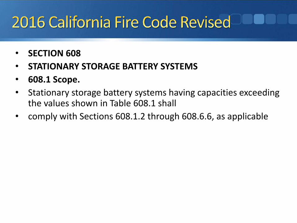
• SECTION 608• STATIONARY STORAGE BATTERY SYSTEMS• 608.1 Scope.• Stationary storage battery systems having capacities exceeding
the values shown in Table 608.1 shall• comply with Sections 608.1.2 through 608.6.6, as applicable
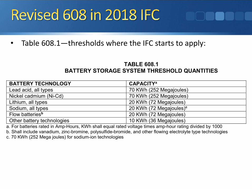
• Table 608.1—thresholds where the IFC starts to apply:
TABLE 608.1
BATTERY STORAGE SYSTEM THRESHOLD QUANTITIES
BATTERY TECHNOLOGY CAPACITYa Lead acid, all types 70 KWh (252 Megajoules) Nickel cadmium (Ni-Cd) 70 KWh (252 Megajoules) Lithium, all types 20 KWh (72 Megajoules) Sodium, all types 20 KWh (72 Megajoules)c Flow batteriesb 20 KWh (72 Megajoules) Other battery technologies 10 KWh (36 Megajoules)
a. For batteries rated in Amp-Hours, KWh shall equal rated voltage times amp-hour rating divided by 1000 b. Shall include vanadium, zinc-bromine, polysulfide-bromide, and other flowing electrolyte type technologies c. 70 KWh (252 Mega joules) for sodium-ion technologies
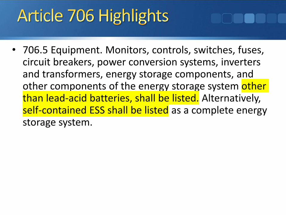
• 706.5 Equipment. Monitors, controls, switches, fuses, circuit breakers, power conversion systems, inverters and transformers, energy storage components, and other components of the energy storage system other than lead-acid batteries, shall be listed. Alternatively, self-contained ESS shall be listed as a complete energy storage system.

• The IRC has been updated in 2018 with some very restrictive wording.• All battery systems must be UL9540 listed—This rules out all non-
lithium-ion batteries since no other technology can currently be listed to UL9540. This is NOT GOOD—need to still install lead-acid for stand-alone and backup power systems. R327.2—(should we not call it a system??)
• Batteries must be installed in non-habitable spaces such as utility rooms, garages, hallways, bathrooms??, storage rooms and outdoor locations.
• If battery is mounted indoors (utility room or garage), consider using make-up air requirements consistent with a combustion water heater appliance.

• January 1, 2019 introduces the new requirements for reduced hazard within the PV array.
• UL 3741, PV Hazard Control, is still under development and there are yet to be any products available under that standard. Lots of good progress.
• 80V limit within the array is most available option for compliance. Dc converters and ac modules work as well as module shutoffs.
• Some companies are trying to develop products to meet the non-metallic option.

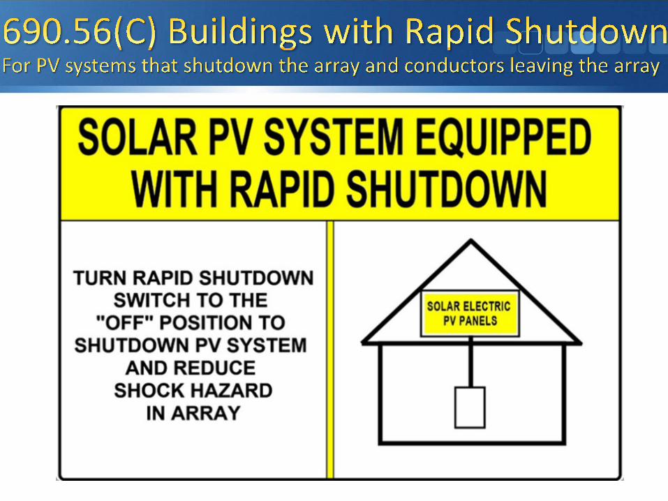


A rapid shutdown switch shall have a label located on or no more than 1 meter (3 ft) from the switch that includes the following wording:
RAPID SHUTDOWN SWITCH FOR SOLAR PV SYSTEM
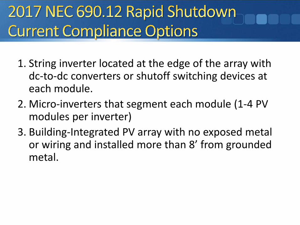
1. String inverter located at the edge of the array with dc-to-dc converters or shutoff switching devices at each module.
2. Micro-inverters that segment each module (1-4 PV modules per inverter)
3. Building-Integrated PV array with no exposed metal or wiring and installed more than 8’ from grounded metal.

• Standard needs to be developed to certify equipment.— Process is wrapping up that is focusing on products
for the 2014 NEC and products outside of array boundary for the 2017 NEC
— As the existing standard process is established for products address outside array boundary, work is starting to develop certification process for listed rapid shutdown PV array products
Mult imode Inverter
Energy storage system disconnect
dc loads
Energy Storage System
Dc coupled multimode system
Inverter output circuits
Elect ric product ion and
dist ribut ion network
Interact ive system disconnectPV power
source PV system disconnect
Interact ive Inverter Inverter output circuit
PV system disconnect
PV power source
c odue systec odu e ( c udes e te )
ay (o ac odu es)
syste dsco ect
Stand-alonesystem loads

Retrofit of Existing PV systems will be commonplace

e gy sto age syste dsco ect
e gy Sto age Syste
c couped ut ode syste
c cuts
Ac coupled multimode system
Energy storage system disconnect
Energy StorageSystem
Mult imode Inverter
Interact ive Inverter Inverter output circuit
PV system disconnect
PV power source
Interact ive system disconnect
Stand-Alone Inverter
Inverter output circuit
PV power source
PV system disconnect
Elect ric product ion and dist ribut ion
network
Stand-alonesystem loads

• New Article 706 in 2017 NEC—Given the rapidly growing market for energy storage systems, the NEC established a new Article 706, Energy Storage Systems (ESS).
• New article is based on 2014 NEC requirements in Article 690 (Solar PV Systems) and Article 480 (Storage Batteries).
• International Fire Code (IFC) approved big changes in Section 608, Stationary Storage Battery Systems, for 2018 IFC.

• Section 608 is heavily revised related to lithium ion batteries.• New requirements include:
• UL9540, Standard for Energy Storage Systems and Equipment, for prepackaged and pre-engineered energy storage systems.
• UL1973, Standard for Batteries for Use in Light Electric Rail (LER) Applications and Stationary Applications, for storage batteries
• Energy management system (battery mgmt.) required for everything except lead acid and ni-cad.
• UL1741 for inverters (same as solar PV)
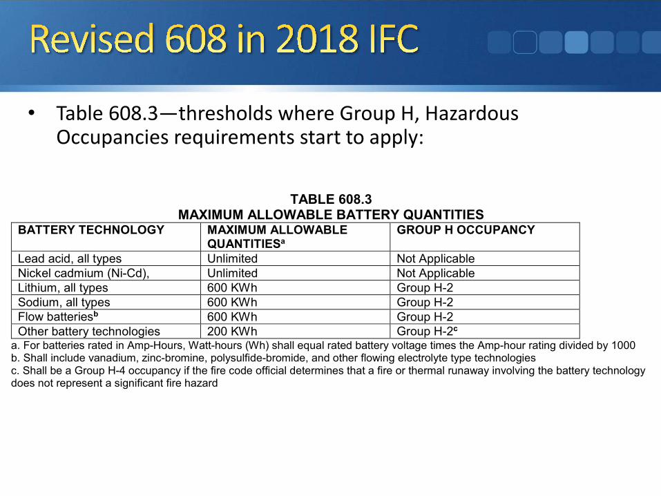
• Table 608.3—thresholds where Group H, Hazardous Occupancies requirements start to apply:
TABLE 608.3
MAXIMUM ALLOWABLE BATTERY QUANTITIES BATTERY TECHNOLOGY MAXIMUM ALLOWABLE
QUANTITIESa GROUP H OCCUPANCY
Lead acid, all types Unlimited Not Applicable Nickel cadmium (Ni-Cd), Unlimited Not Applicable Lithium, all types 600 KWh Group H-2 Sodium, all types 600 KWh Group H-2 Flow batteriesb 600 KWh Group H-2 Other battery technologies 200 KWh Group H-2c
a. For batteries rated in Amp-Hours, Watt-hours (Wh) shall equal rated battery voltage times the Amp-hour rating divided by 1000 b. Shall include vanadium, zinc-bromine, polysulfide-bromide, and other flowing electrolyte type technologies c. Shall be a Group H-4 occupancy if the fire code official determines that a fire or thermal runaway involving the battery technology does not represent a significant fire hazard

• UL9540 is still a new standard (only a few products certified so far—mostly with Intertek)
• NFPA 855: Standard for the Installation of Stationary Energy Storage Systems is nearly published.
• Interconnection standards will evolve with PV+Storage systems.
• The 2020 NEC and future IFC and IBC revisions will continue to evolve the safety standards.

• Codes and standards are rapidly changing.
• New certification processes will help improve safety and design.
• Need to make room for existing and advanced lead-acid technologies.