W.H. Mason Configuration Aerodynamics Classmason/Mason_f/SubsonicWingsPres.pdfChoices: VLMpc,...
52
Subsonic Wings an introduction and review W.H. Mason Configuration Aerodynamics Class
Transcript of W.H. Mason Configuration Aerodynamics Classmason/Mason_f/SubsonicWingsPres.pdfChoices: VLMpc,...

Subsonic Wingsan introduction
and review
W.H. MasonConfiguration Aerodynamics Class

Topics
• Subsonic Wing Calculation Method Review• Aero of High Aspect Ratio Wings• Slender Wings

VLM Methods – a way to get insight
• Linear, inviscid aerodynamics – strictly subsonic
• Ignores thickness – bc’s applied on the mean plane• VLM is essentially a 3D thin airfoil theory
• Finds ΔCp, not the upper/lower surface pressures
• Very handy and accurate as seen below
• Really good for understanding interacting surface ideas
Choices: VLMpc, Tornado, AVL, JKayVLM, XFLR5, VSPaero
First, review a great tool to understand wing aero

The classic method
Usually employs aflat wake to downstreaminfinity – a linear problem
• Each panel is modeled using a horseshoe vortex of as yet unknown strength (has bound and trailing vortex “legs”)• The Biot-Savart Law is used to compute the induced velocity at a control point due to the contributions from each horseshoe vortex• Summing up the contributions from each horseshoe vortex and satisfying the boundary conditions leads to a linear system of algebraic equations for the unknown vortex strengths
Need to include the contributions from both sides of the wing!

To complete the method
• The classical VLM method puts the bound vortex on the ¼ chord of the panel, and the control point is placed at the ¾ chord point
• The boundary condition satisfies the angle of attack, the camber slope, and the wing twist. They are simply added up so that you can pick how to divide up the contributions. This is basically a bookkeeping problem.
• Solving the linear system for the horseshoe vortex strengths is an analysis problem.
• Using the same system, but specifying the vortex strengths you can find the required camber and twist, a design problem
• Many variations have been used, lots of Refs in the text.

VLM Models and Tips

Convergence with number of “panels”
F/A-18
0
2
4
0 40 80 120 160 200 240Total number of panels
Vortex Lattice Method
(5) (9)( ) Number of chordwise panels
Δ Neutralpoint,
percent c

Panel Models

F-15 3-Surface VLM Model

Three-Surface F-15 Longitudinal Derivatives

Canard Height Effect

F-15 horizontal tail effectiveness

F-15 aileron effectiveness

Warren-12 Test Case
Note: CM about wing apex,Reference chord is 1.0

The key:Define it for others!
The reference trap wing
Source: Stinton, Design of the Airplane
Comment: Reference Area(s)

For More On Calculation Methods
http://www.cambridge.org/us/academic/subjects/engineering/aerospace-engineering/applied-computational-aerodynamics-modern-engineering-approach

Aerodynamics of High Aspect Ratio Wings
• Planforms
• Spanloads
• Pitching moment and pitchup
• Aerodynamic Center
• Isobars/Twist
• Camber
• 2D-3D connection
• Canard and Ground Effects
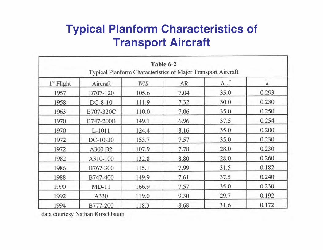
Typical Planform Characteristics ofTransport Aircraft

Clearly the A380 pays a price to satisfy the 80 meter gate box limit
6
7
8
9
10
11
12
1950 1960 1970 1980 1990 2000 2010
Aspect Ratio Trends - Commercial Transports
AR
Ist flight date
B787
A380B707-120
DC-8-10
B747-200B
B707-320C
L-1011
A300
DC-10-30
A310
B767
B747-400MD-11
A330
B777-200
A340-500
A330-300B777-300ER

Forward, Unswept and Aft Swept Planforms, AR = 2.8

Related Spanloads and Section Lift Coefficients
0.00
0.20
0.40
0.60
0.80
1.00
1.20
1.40
1.60
0.0 0.2 0.4 0.6 0.8 1.0y/(b/2)
Spanload,
Warren 12 planform, sweep changed
aft swept wing
unswept wing
forward swept wing
ccl / ca
0.00
0.20
0.40
0.60
0.80
1.00
1.20
1.40
0.0 0.2 0.4 0.6 0.8 1.0y/(b/2)
Section CL
Warren 12 planform, sweep changed
aft swept wing
unswept wing
forward swept wing
For an untwisted planar wing

Forward, Unswept and Aft Swept Planforms, AR = 8

Related Spanloads and Section Lift Coefficients
0.2
0.4
0.6
0.8
1.0
1.2
1.4
1.6
0.0 0.2 0.4 0.6 0.8 1.0
Spanload,
y/(b/2)
Aspect ratio 8 wings
aft swept wing
unswept wingforward swept wing
ccl / ca
0.00
0.50
1.00
1.50
0.0 0.2 0.4 0.6 0.8 1.0
Section CL
Aspect ratio 8 planforms
aft swept wing
unswept wing
forward swept wing
y/(b/2)
For an untwisted planar wing

Example: VLM Pitching Moment agrees well with data until wing pitchup
-0.06
-0.04
-0.02
0.00
0.02
0.04
0.06
0.08
-0.4 -0.2 0.0 0.2 0.4 0.6 0.8 1.0 1.2
Cm
CL
AR = 10, Λc/4 = 35°, λ = 0.5data from NACA RM A50K27
Re = 10 million
x ref = c/4
VLMpc calculation

A confusion factor with modern wingsThe LE and TE are scheduled with Mach and AlphaFrom AIAA F-16 Case Study

Note – the curves don’t go to 0.25 at 0 deg sweep!
0.20
0.25
0.30
0.35
0.40
0.45
-40 -30 -20 -10 0.0 10 20 30 40
Aerodynamic Center Variation with Sweep
aero ctr,% mac
C/4 sweep, deg.
Vortex Lattice AnalysisNS = 25, NC = 8 (200 panels)
AR = 10,taper = 0.5
AR = 6,taper = 1/3

Low Aspect Ratio Wing Neutral Point (ac)For a rectangular wing it moves forward!
From Schlichting and Truckenbrodt,Aerodynamics of the Airplane
AR
Discovered while making pre-test estimates
Inboard Wing built/tested at VT
0.25
0.05
1 5 73

Isobars on untwisted/uncambered swept wing- needs aero design!
Note: this is actually a transonic case, M = 0.93, α = 2°from AFFDL-TR-77-122, February 1978.
These funny NACA report numbers denote series classified at the time, “L” stands for Langley, reports starting with “A” denote Ames
Without twist and camber: don’t get full effect of sweep

Now: DesignTypical Twist Distributions
- to improve isobars/spanloads -
-1.00.01.02.03.04.05.06.07.0
0 0.2 0.4 0.6 0.8 1
θ,deg.
y/(b/2)
-1.00.01.02.03.04.05.06.0
0 0.2 0.4 0.6 0.8 1
θ,deg.
y/(b/2)
Aft Swept Wing Forward Swept Wing
from LAMDES on the software website
A LAMDES artifact

Design Typical Camber Variation
-0.01
0.00
0.01
0.02
0.03
0.04
0.05
-0.2 0 0.2 0.4 0.6 0.8 1 1.2
(z-zle)/c
x/c
η = 0.925η = 0.475
η = 0.075
Cambers from the LAMDES code on the software website

Relating 2D and 3D
The airfoil problem is converted to 2D (normal), solved (designed), and put in the wing 3D
c2D = cs cosΛM 2D = M∞ cosΛ
t / c)2D = t / c)s / cosΛcL2D = cLn / cos
2 Λ

Now Canards Canard-Wing Interaction
canard wake extends to indinitywing wake not shown
A A
Canard wakestreams overwing
-2.0-1.5-1.0-0.50.00.51.01.5
-2 -1.5 -1 -0.5 0 0.5 1 1.5 2
w
Downwash from canard across wingat Section A-A
Upwash outboardof canard tips

Look at example from WT testingWing tested at NASA Langley, NASA TN D-7910 by Blair GlossSeveral combinations tested, we illustrate the outlined wing and canard
Note: all the test results are tabulated in the NASA TN

Canard Effects on Lift and Moment
NASA TN D-7910 by Blair Gloss
-0.50
0.00
0.50
1.00
1.50
-10 0 10 20 30 40 50
Canard Effect on LIft- minimal at low alpha -
CL
Alpha - deg.
Wing Alone
Wing - Canard
-0.25
-0.20
-0.15
-0.10
-0.05
0.00
0.05
0.10
-10 0 10 20 30 40 50
Canard Effect on Pitching Moment- large effect on moment -
CM
Alpha - deg
Wing Alone
Wing - Canard

Example for Minimum Induced Drag Calculations
Sample case in John Lamar’s NASA TN with LAMDES

Canard Wing Induced Drag
0.0200
0.0250
0.0300
0.0350
0.0400
-0.4 -0.3 -0.2 -0.1 0.0 0.1 0.2 0.3 0.4
CDi
Δx/cForward Aft
Canard lift must benegative to trim
M = 0.3, CL = 0.5
Canard heightabove wing ,
0.1
0.2
z/b
0.3
Computations from LamDes
Advantage of verticalseparation clearly evident
Static Margin
Stable Unstable
Advantage of relaxedstatic stability evident
Note: The sample case may not be a good design, the canard is too big.

Typical Required Twist Distribution
-1.00.01.02.03.04.05.06.0
0.0 0.2 0.4 0.6 0.8 1.0
θ,
y/(b/2)
in presenceof canard
withoutcanard
canard tipvortex effect
deg.
-2.00.02.04.06.08.0
0.0 0.2 0.4 0.6 0.8 1.0
θ
y/(b/2)
withoutcanard
in presenceof canard
canard tipvortex effect
Aft Swept Wing Forward Swept Wing
Actual twist values are heavily dependent on the canard load!

Some Variations: Tip treatment
from Feifel, in NASA SP-405, 1976
A Whitcomb “winglet”
The “Raked Wingtip” used on the Boeing 767-400
from Kroo, Ann. Rev. of Fluid Mech., 2001
Rounding the intersection leads to a “blended winglet”
Note “Yehudi”

Ground Effects from VLM
1.0
2.0
3.0
4.0
5.0
6.0
7.0
8.0
0.0 0.2 0.4 0.6 0.8 1.0 1.2 1.4
CLα
h/c
AR4
2
1
Solid lines: computed using JKayVLMDashed lines: from Kalman, Rodden and GiesingSymbols: Experimental data
hU∞
c
c/4
-0.40
-0.30
-0.20
-0.10
0.00
0.10
0.20
0.0 0.2 0.4 0.6 0.8 1.0 1.2 1.4
CMα
h/c
Solid lines: computed using JKayVLMDashed lines: from Kalman, Rodden and Giesing
AR124

But ground effect can be complicatedA G650 crashed in New Mexico, April 2, 2011 – both pilots diedWhy? CLmax IGE can be less than CLmax OGE with flaps down
Data showed adverse flap effects for CLmax, NACA TN 705, 1939
IGE: In Ground Effect
OGE: Out of Ground Effect

A completely new category Slender Wings
See NASA CP 2416

Consider Two Entirely Different
Wing Concepts
0.00
1.00
2.00
3.00
4.00
5.00
6.00
7.00
0.0 2.0 4.0 6.0 8.0 10
Wings Transition from Slender Wing Theoryto High Aspect Ratio Wings with Airfoils
CLα-radians
Aspect Ratio
Slender WingTheory
2D lift curve slope
Finite Wing Lift Curve SlopeVariation with Aspect Ratio
Polhamus NACA TN 1862 (1949)also in Nicolai
Think of high aspect ratio wings as havingairfoils.Slender wings don’thave “airfoils” per say,Instead, think of spanwise sections.
High aspect ratio wings approach the 2π slopeThe slender wing slope is (π/2)AR

Laser Light Sheet Leading Edge Vortex Flow
Aviation Week & Space Technology, July 29, 1985
Light Sheet is a great way to see the LE vortex
Northrop IR & D example of flow over a delta wing configuration.
Exhibited at the 36th Paris air show.

Drawback?It’s “draggy” lift
Vortex Lift
https://www.youtube.com/watch?v=5_jt4x_TpOIThanks to James Stewart you can see a video of the flowfield:

The Polhamus LE Suction Analogy
Edward C. Polhamus,NASA TN D-3767

Another View of the Suction Analogy
R.M. Kulfan, Wing Geometry Effects on Leading Edge Vortices, AIAA 79-1872

Results of the Polhamus Suction Analogy
0.00
0.500
1.00
1.50
2.00
0.0° 10.0° 20.0° 30.0° 40.0°
CL
α
AR = 1.5 (Λ = 69.4°)
VortexLift
PotentialLift
Experimental data fromBartlett and Vidal
Prediction from PolhamusLeading Edge Suction Analogy

Reduce Drag with a Vortex Flap?The Concept
The reality?
Flight International, 16 March 1985
This concept was briefly popular, but it proved too hard to achieve.

Strakes are also low aspect ratio slender wings. Because they don’t stall, even low tail designs can have
a nose-down moment problem
F-16
ForebodyStrakes
Note: Eventually the horizontal tail size was increased 25%
Note: you can apply the LE Suction Analogy to the strake in VLMpc
This is a Hybrid Wing Concept

The Concorde Exploited Both Ground Effects and Vortex Lift to be Even Somewhat Practical
From Poisson-Quinton, Sustained Supersonic Cruise Aircraft Experience
VortexBurst

And VLM works for Hypersonic Class Concepts
Jimmy Pittman and James Dillon, “Vortex Lattice Prediction of Subsonic Aerodynamics of Hypersonic Vehicle Concepts,” Journal of Aircraft, October 1977, pp. 1017-1018.

To Conclude
This just gives you the very basics- no end to planform concepts, invent one yourself!