WETS Industry Forum - Hawaii National Marine Renewable...
23
US Navy W ave E nergy T est S ite Kaneohe, HI Presented by: Luis A. Vega Ph.D., HNEI, University of Hawaii September 24, 2014
Transcript of WETS Industry Forum - Hawaii National Marine Renewable...

US Navy
Wave Energy Test Site Kaneohe, HI
Presented by: Luis A. Vega Ph.D., HNEI, University of Hawaii
September 24, 2014

2
MHK Testing in Hawaii (excluding OTEC)
What do you do to support/facilitate testing?
• Team (Navy/UH) capabilities
• Activities in support of in-water testing
• Developer‘s support

3
WETS Notional Layout
• Shore station facility • Moorings
– New 3-point moorings (60m & 80m)
– Existing 3-point mooring (30m depth)
• Power cables – One new trunk cable
to one splice box for each deep site
– Existing subsea cable to 30m site

4
WETS Modus Operandi
• NAVFAC – MCBH Kaneohe Bay, Site Host – Permitted berths with primary mooring, submarine power + data cables – Grid connection infrastructure + Interconnection Requirements Study (IRS) – Device-specific permits (CATEX and ACOE permits) – Cooperative Research and Development Agreement or Navy contract – Office space
• HNEI-UH – Evaluate WEC system performance (power output as function of waves) – Mooring system & power cable life expectancy evaluation – Environmental impact (acoustics, EMF, ecological surveys) – Calibrated 7.5 days wave forecasting for operations planning
• Tenants − Must be selected competitively through Navy or DOE process (e.g., BAA, FOA) − Deploy and retrieve device (connect to mooring and submarine cable) − Provide hawser for mooring connection and umbilical for connecting to splice box − Data acquisition of subsystem parameters − HECO Standard Interconnection Agreement (SIA) + Rule 14 Exhibit A application

5
WETS Research Objectives
• WEC Device Independent Performance Assessment – WEC device modeling
• Theoretical devices and Numerical models (i.e., seakeeping analysis) • Calibration of models with test data from WETS
– Develop power matrices (power output vs. wave input) – Analyze durability issues (moorings/devices) and develop protocols
• Diver and ROV inspections • Document/analyze routine/unplanned maintenance
– Improve wave forecast modeling with field measurements (e.g., Waveriders)
• Environmental Impact Quantification and Monitoring – Device acoustic signatures relative to ambient conditions
• As function of seasonal changes in biologic and vessel activity • As function of weather/wave conditions
– Device/cable electromagnetic signatures • Test deployments of developmental instrumentation • Examine EMF relative to ambient, varying transmission methods
– Sediment transport – Diver/ROV ecological surveys (examine changes in presence of WECs)

6
Why WETS in Kaneohe, Oahu?
** Year-round data collection in a wide range of wave conditions is possible!
Commercial Sites: Deploy/Retrieve in May to Sep
WETS: larger Deploy/Retrieve
window
**

7
Daily Wave Power Flux
Device performance can be fully evaluated at WETS under all operational conditions.

8
• Potential Users: Industry surveys revealed that the most mature technologies were of two types.
• Approach: Expand facility from one- to three-permitted berths (30m, 60m, and 80m water depths).
WETS Infrastructure Design Approach
− Point Absorber (e.g., NWEI, Fred.Olsen Ltd, Columbia Power, Carnegie, OPT)
− Oscillating Water Column (e.g., Ocean Energy)
S&ST

9
HNEI-UH Team: Supported NAVFAC in WETS Environmental Assessment and Design
Wave & Current Climate
Bathymetry & Sediment Profile
Output − Mooring Design by SST − Power cable routing
Waverider In-situ Measurements

10
Mooring Leg Profile
10

11
Healey Tibbitts barge, with 2 remaining mooring legs (of 6)
Floats 5.8 tonnes Sinker weights
Bruce anchors
September 11, 2014

12
Three Surface Floats per Berth

13
Tugs positioning barge for anchor placement (or cost effective dynamic positioning
September 11, 2014

14
10 tonnes Bruce anchor ∼ 300 tonnes holding capacity
September 11, 2014

15
Wave Scatter: Occurrence vs. Hs/Te
HNEI-UH Team: Will Support Testing Operations and Provide Independent Assessment of Performance
Wave & Current Climate
Device Power Performance: - Electrical output vs. wave parameters
Database to address regulatory and
stakeholder issues
WEC Device Environmental Impact − chemical & ecological site surveys − acoustic & EMF signatures
Power Matrix: kW vs. Hs/Te
X =
kWh vs. Hs/Te

16
WETS Schedule
• Existing 30m berth to be occupied by NWEI (Nov. 2014) • HNEI Waverider® buoy operational (October 2012)
– Provides real-time wave data for WEC device performance and to calibrate models to provide 7.5 days of wave forecast info for test planning
– CDIP Station 198
• WETS expansion for 60m and 80m berths − Engineering design by Sound & Sea Technology (Jan 2014)
• Signed FONSI and Environmental Assessment (Feb 2014) • Hardware procurement (in process) • Deep water infrastructure construction (mooring done/cable 2015) • Deep water berths operational (Summer 2015) [Dates updated September 2014]

17
DOE and US Navy Funding for UH/HNEI
•Site Preparation
–Assist Navy with Sound & Sea design of 3-berth Test Site –Facilitate/Support environmental permitting process
•Conduct Environmental Impact Measurements –Acoustic, EMF, Ecological, Sediment Transport
•Conduct Independent Performance Assessments –Characterize wave resource (forecast/hindcast) –Assess device durability –Develop device power matrices –Evaluate alternative modeling approaches
•Provide Site-Dedicated Support Vessel
Dep
artm
ent
of
En
erg
y N
AV
FAC

18
MHK Testing in Hawaii (excluding OTEC)
Questions?

19
Wave Energy Test Site (WETS)
• Objective: Provide USA location for technical evaluation and environmental data collection studies of in-water WEC devices.
• Approach: Expand facility from one- to three-permitted berths (30m, 60m, and 80m water depths).

20
WETS Site Specific Parameters
Component Shallow site Deep sites
Water depth One @ 30m Two (60m and 80m)
Maximum transmitted power
250kW @ 4160V 1 MW @11,500V
3-point moorings
• three (3) sub-surface floats
• two (2) rock-bolted anchor bases and one gravity anchor
• three (3) surface floats • three (3) drag embedment
anchors

21
WETS Deep Site: Notional Parameters

22
Electrical Generation with Hypothetical “1 MW” Point Absorber
Site Wave Scatter
Annual Po (kW/m)
Pauwela (Maui) 73 m Depth
Hindcast (1990-2009)
3 km offshore
23
Grays Harbor (WN) 40 m Depth
NDBC (1987-2008)
9 km offshore
31
Col. Rvr Bar (WN/OR) 135 m Depth
NDBC (1999-2008)
40 km offshore
40
Theoretical Resource
Annual MWh Max hour Po (kW/m)
1,560 CF: 0.18
350
2,025 CF: 0.23
1160
2,630 CF: 0.30
1420
Technical Resource
Survival
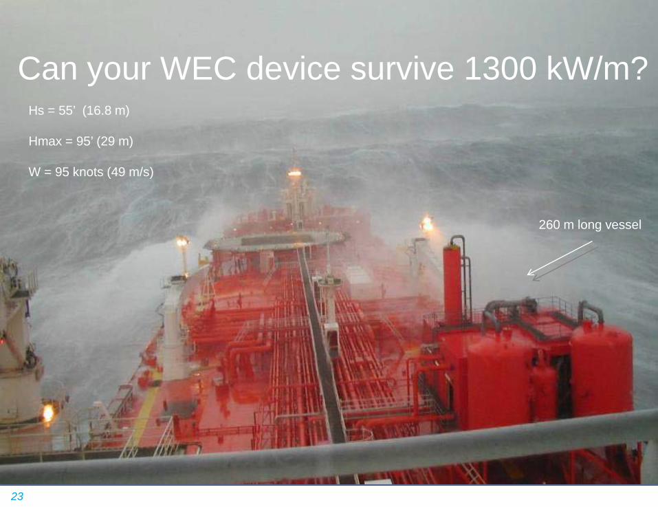
23
Can your WEC device survive 1300 kW/m?
260 m long vessel
Hs = 55’ (16.8 m) Hmax = 95’ (29 m) W = 95 knots (49 m/s)