Wet blast system WET BLAST FLEX with W-92 booster pump ... · 1. 140 l pressure blast pot with PT...
18
Revision: 5.1 Clemco International GmbH Carl-Zeiss-Straße 21 Phone.: +49 (0) 8062 – 90080 83052 Bruckmühl Mail: [email protected] Germany Web: www.clemco-international.com O W N E R ’ S M A N U A L Wet blast system WET BLAST FLEX with W-92 booster pump, SC2048 pot, 500 l water tank and KB-52-1 wet blast head
Transcript of Wet blast system WET BLAST FLEX with W-92 booster pump ... · 1. 140 l pressure blast pot with PT...

Revision: 5.1
Clemco International GmbH Carl-Zeiss-Straße 21 Phone.: +49 (0) 8062 – 90080
83052 Bruckmühl Mail: [email protected] Germany Web: www.clemco-international.com
O W N E R ’ S M A N U A L
Wet blast system WET BLAST FLEX
with W-92 booster pump,
SC2048 pot, 500 l water tank and
KB-52-1 wet blast head

2
TABLE OF CONTENTS
1 SCOPE .................................................................................................................. 3
2 APPLICATION AND RESTRICTIONS .................................................................. 3
3 DESCRIPTION OF THE EQUIPMENT .................................................................. 4
4 FUNCTIONAL PRINCIPLE OF THE ENTIRE SYSTEM ....................................... 5
4.1 COMPONENTS ............................................................................................................. 6
4.1.1 2048 type blast pot ............................................................................................................. 7
4.1.2 KB-52-1 wet blast head ...................................................................................................... 7
4.1.3 W-92 type booster pump .................................................................................................... 8
4.1.4 Water tank ........................................................................................................................... 8
4.2 PNEUMATIC DIAGRAM .................................................................................................. 9
4.2.1 Detailed description of the four possible functions ............................................................. 9
5 OPERATION ....................................................................................................... 11
5.1 REQUIREMENTS ........................................................................................................ 11
5.2 SET-UP FOR INITIAL INSTALLATION AND REINSTALLATION .............................................. 11
5.3 DAILY SET-UP ............................................................................................................ 12
5.4 START-UP AND OPERATION ........................................................................................ 13
5.5 SHUTDOWN AFTER FINISHING WORK ........................................................................... 13
5.6 SHUTDOWN WHEN MOVING EQUIPMENT....................................................................... 14
6 MAINTENANCE .................................................................................................. 14
6.1 GENERAL NOTES ....................................................................................................... 14
6.2 DAILY MAINTENANCE CHECK LIST ................................................................................ 14
6.3 WEEKLY MAINTENANCE CHECK LIST ............................................................................ 15
6.4 MONTHLY MAINTENANCE CHECK LIST .......................................................................... 15
7 TROUBLESHOOTING ........................................................................................ 15
8 REPLACEMENT PART LIST .............................................................................. 16
3
1 Scope
This owner’s manual contains information regarding the operation and maintenance of the WET BLAST
FLEX wet blast system, consisting of:
As frame-mounted:
1. 140 l pressure blast pot with PT steel media metering/stop valve
2. KB-52-1 wet blast head
3. W-92 booster pump with attached filter regulator
4. 500 l water tank
5. High-pressure water hose and suction hose.
The following owner’s manuals should additionally be observed:
1. Owner’s manual of single-chamber blast tool for 1 blaster with pneumatic metering
valve, pilot pressure regulator, TLR and HMS
2. Owner’s manual of PT type blast media metering valve
3. Owner’s manual of pilot pressure regulator
4. Owner’s manual of RLX III –ACS remote control deadman handle
5. Owner’s manual of W-92 booster pump
2 Application and restrictions
The WET BLAST FLEX wet blast system may be operated only with ferrite-free single-use blast media
with grit size between 0.7 µm and 1.2 µm.
Max. permissible operating pressure: 12 bar
Min. required operating pressure: 5.5 bar (necessary to open PT type metering valve)
Main dimensions of the entire system:
Length Width Height Weight
2000 mm
(without hoses)
800 mm 1500 mm
(without crane eyes)
420 kg
Table 1: Main dimensions

4
3 Description of the equipment
The full system (Figure 1) is composed of the following main components:
Figure 1: WET BLAST FLEX wet blast system
1. 2048 type 140 l blast pot
2. KB-52-1 wet blast head
3. W-92 booster pump
4. Water tank
As a compact unit, it allows four different blast applications that can be controlled via the ACS slide
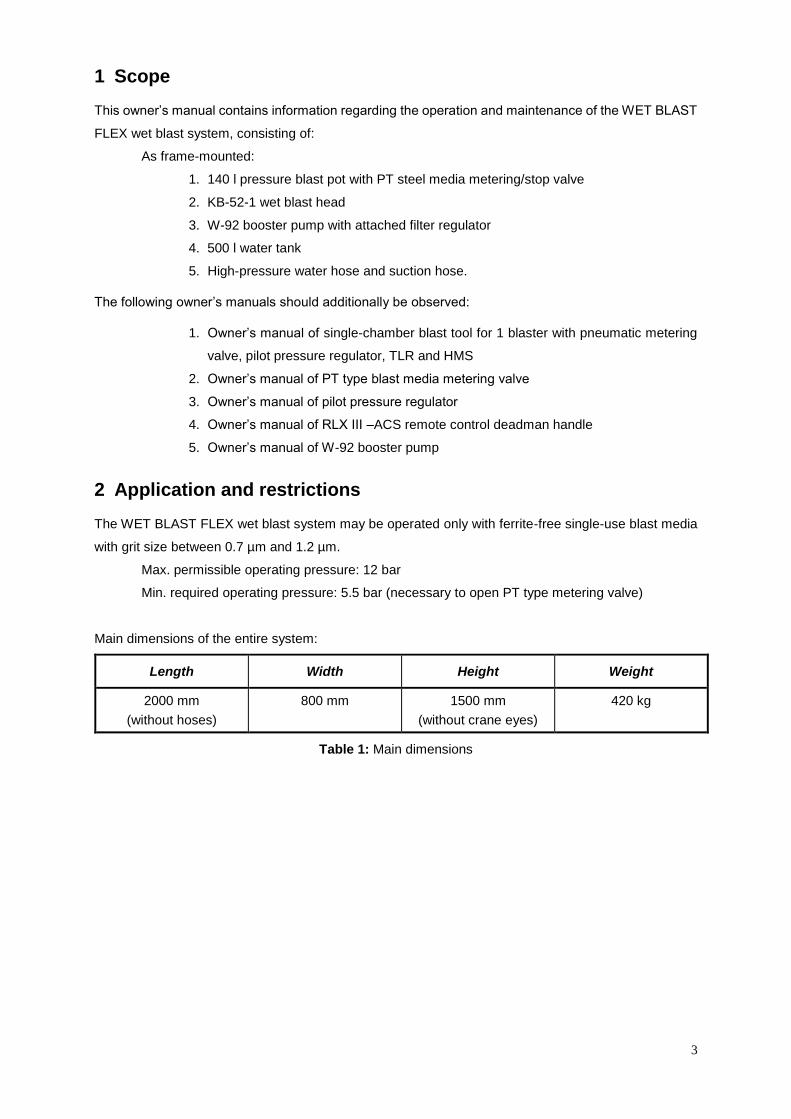
valves on the dual-function RLX remote control deadman handle. Figure 2 shows the remote control
deadman handle with both ACS slide valves that are installed for switching on and off of the blast media
and water supply, respectively:
The ACS (A) slide valve (with the red hose) is used to open and close the blast media supply.
The ACS (B) slide valve (with the blue hose) is used to open and close the water supply.
The ACS valves are opened in each case by sliding in the direction of arrow and are active when the
deadman handle is pressed.
The four possible functions are as follows:
a) Dry blasting – air and blast media
b) Washing down – air and water
c) Wet blasting – air, water and blast media
d) Blowing off – air only
1 1 1
2
4
3
5
Figure 2: Deadman handle with ACS slide valves
Process Actuation
a Dry blasting
(air and blast media)
Press the RLX deadman handle and
open the ACS(A) slide valve with the red hose
(ACS(B) with blue hose closed)
b Washing down
(air and water)
Press the RLX deadman handle and
open the ACS(B) slide valve with the blue hose
(ACS(A) with red hose closed)
c Wet blasting
(air, water and blast media)
Press the RLX deadman handle and
open both ACS slide valves
d Blowing off
(air only)
Press the RLX deadman handle and
close both ACS slide valves
Table 2: Description of functions of the remote control deadman handle
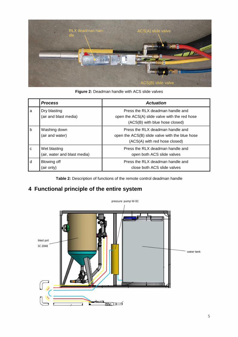
4 Functional principle of the entire system
RLX deadman han-dle
ACS(A) slide valve
ACS(B) slide valve

6
The WET BLAST FLEX wet blast system is a pressure blast machine which is connected to a self-
priming pump (W-92) and a 500 l water tank. The pressure blast machine and the W-92 booster pump
are supplied with compressed air in parallel. The compressed air is cleaned in the connection filter of
the booster pump and then drives the self-priming water pump via an air motor. The primed and pres-
surised water is pumped to the KB-52 wet blast head via a high-pressure water hose. The water is
directly injected into the blast media air flow (blast nozzle) via the wet blast head and is atomised. The
water volume can be regulated via the needle valve as well as the nozzle of the KB-52-1. The water
binds the dust that would normally be created during blasting. The machine can also be used for dry
blasting, washing down or blowing off thanks to the intelligent control.
4.1 Components
The complete system is composed of the following main components:
Figure 3: Main components of the WET BLAST FLEX wet blast system
1) 2048 type 140 l blast pot
2) KB-52-1 type wet blast head
3) W-92 type booster pump
4) Water tank (500 l)
1 1 1
2
4
3

7
4.1.1 2048 type blast pot
Figure 4: Blast pot
Please follow the separate owner’s manual regarding this.
4.1.2 KB-52-1 wet blast head
The water is injected from the water tank through the high-pressure hose (Item 3) into the blast media
air flow (blast nozzle) directly via the wet blast head and is atomised. The water volume can be regu-
lated via the needle valve (Item 1) as well as the nozzles of the KB-52-1. The water can be shut off
completely with the stop-cock (Item 2).
Figure 5: KB-52-1 wet blast head
Item 1
Item 2
Item 3

8
4.1.3 W-92 type booster pump
The W-92 booster pump is self-priming and is supplied directly from the water tank. The sieve (Item 1)
holds back dirt from the water tank and supply line.
For further details regarding the booster pump please consult the separate user manual.
Figure 6: W-92 type booster pump
4.1.4 Water tank
The water tank installed in the WET BLAST FLEX is made from UV-stabilised polyethylene. It has a
capacity of 500 litres and a ¾” connection. It includes a scale for reading off the water level.
Figure 7a-Water tank Figure 7b-Water connection at the tank
Figure 7a & 7b: Water tank and water connection
Item 1

9
4.2 Pneumatic diagram
Figure 8: WET BLAST FLEX pneumatic diagram
The compressed are is supplied to the system through the water separator (Item 8).
4.2.1 Detailed description of the four possible functions
a) Function 1 – Dry blasting (air & blast media)
ACS(A) slide valve (Item 19.1) on the deadman handle at the red hose (slide in the direction of
the arrow!) opened
ACS(B) slide valve (Item 19.2) at the blue hose closed.
If the deadman handle (Item 19) is pressed, the compressed air flows into the blast pot through
the pilot pressure regulator (Item 6).
At the same time:
- the closing plug (Item 14) closes the filler opening with O-ring (Item 15).
- the TLR outlet valve (Item 11) closes
- the blasting process begins.
The desired blast pressure is set with the pressure regulator (Item 7) via the pilot pressure
regulator (Item 6).
If the deadman handle is released:
- the TLR outlet valve (Item 3) opens
- the pot is ventilated.
The blast media metering valve (Item 10) regulates the blast media supply in the air flow. It is
opened and closed pneumatically through the ACS(A) (Item 19.1) slide valve. When ACS(A)
(Item 19.1) is closed, only air and no blast media flows through the blast media hose.

10
When ACS(A) (Item 19.1) is opened, then the blast media flows through the blast-hose, under
pressure, to the blast nozzle (Item 18). As soon as the blaster releases the deadman handle
(Item 19), the blasting process is interrupted and the blast pot is ventilated. The TLR outlet valve
(Item 3) opens. The bang is attenuated via the silencer (Item 2).
b) Function 2 – Washing down (air & water)
If no blast media but only water is needed in the application, the following steps are necessary: -ACS(A) slide valve (Item 19.1) at the red hose closed
-ACS(B) slide valve (Item 19.2) at the blue hose (slide in the direction of the arrow!) opened.
The compressed air is supplied to the system through the water separator (Item 8).
If the deadman handle (Item 19) is pressed, the compressed air flows into the pot through the
pilot pressure regulator (Item 6).
As a result:
- the closing plug (Item 14) closes the filler opening with O-ring (Item 15).
- the TLR outlet valve (Item 3) closes.
- air flows through the 3/2-way valve (Item 7.2) to the deadman handle (Item 19) and
via the filter unit (Item 21) to the pump (Item 22).
This is self-priming and is supplied directly from the water tank (Item 28). The sieve (Item 23)
holds back possible dirt.
The water supply can be regulated with the ball valve (Item 29) located on the water tank and
interrupted for repair purposes.
The wet blast head (Item 25) is supplied with water via the high-pressure hose (Item 24). The
water is injected directly into the blast media air flow (blast nozzle Item 18) via the wet blast
head and is atomised. The water volume is regulated by the needle valve (Item 27) as well as
the nozzle (integrated in the wet blast head –Item 25). Additionally the water supply can be
completely interrupted via the stop-cock (Item 26).
If the deadman handle is released:
- the TLR outlet valve (Item 3) opens
- the pot is ventilated.
- the water supply is interrupted.
c) Function 3 – Wet blasting (air, water & blast media) If blast media and water are needed in the application, the following steps are necessary: -ACS(A) slide valve (Item 19.1) at the red hose (slide in the direction of the arrow!) opened
-ACS(B) slide valve (Item 19.2) at the blue hose (slide in the direction of the arrow!) opened.
As a result of the pressed deadman handle, both blast media and water flows into the air stream.
The water binds the dust that would normally be created during blasting.
If the deadman handle is released:
- the TLR outlet valve (Item 3) opens

11
- the pot is ventilated
- the water and blast media supply is interrupted
d) Function 4 – Blowing off (air) If only air is needed in the application for blowing off the parts, the following steps are necessary: - ACS(A) slide valve (Item 19.1) at the red hose closed
- ACS(B) slide valve (Item 19.2) at the blue hose closed.
As a result of the pressed deadman handle, neither water nor blast media can flow in the circu-
lation and therefore the workpiece can be only blown off and cleaned, respectively.
5 Operation
5.1 Requirements
The following technical data and maximum values of the WET BLAST FLEX must be observed during
operation:
Maximum air inlet pressure for the sand blast pot = 12 bar
Theoretical ratio (water pressure to air pressure) = 4 : 1
Water pump flow per double stroke = 75 cm3
Maximum water volume pumped = 15 l/min
Air consumption of the W-92 booster pump at 8 bar = 0.15 m3/min
Table 3: Technical data
5.2 Set-up for initial installation and reinstallation
(1) Shutting down the wet blast
system
Level surface
Near the compressed air system
(2) Install SC2048 pressure
blast pot
Follow the owner's manual of the pressure blast pot!
Connect compressed air supply
Fill with blast media
Adjust all relevant parameters
(pressure, blast media flow, etc.)
(3) Wet blast head (KB-52) al-
ready installed
Connect blast-hose with nozzle and holder to wet blast head.
Connect remote control hoses to the machine as well
12
(4) Install W-92
booster pump
Follow the owner's manual of the booster pump!
Compressed air (set compressed air regulator to max. 8 bar)
(5) Install water tank Unscrew safety lock
Open tank cover
Add water (max. 500 l)
Close tank cover and screw safety lock back on again
(6) Remove air from the system Supply compressed air to the W-92 booster pump (open ball
valve)
Set pump pressure regulator to around 3 bar
Open the ball valve on the wet blast head
Leave the W-92 booster pump running until only water comes
out of the nozzle (no air left in the system)
(7) Put on the protective equip-
ment
Protective suit
Air-fed helmet with correct connection to the breathing air supply
(breathing air filter) and adjustment of the air volume with an air
control valve attached to the belt
Leather gloves and safety shoes
5.3 Daily set-up
Not necessary if an initial installation or reinstallation has already been performed in accordance with
chapter 5.2.
(1) Pressure blast pot Follow the owner's manual of the pressure blast pot!
Connect compressed air supply
Fill with blast media if applicable
check all relevant parameters
(pressure, blast media flow, etc.)
(2) Water tank Ready for use (top up water if necessary)
(3) Remove air from the sys-
tem
Follow the owner's manual of the pressure blast pot!
Supply compressed air to the W-92 booster pump (open ball
valve)
Set pump pressure regulator to around 3 bar.
Open the ball valve on the wet blast head.
13
Leave the W-92 booster pump running until only water comes out
of the nozzle (no air left in the system)
(4) Put on the protective equip-
ment
Protective suit
Air-fed helmet with correct connection to the breathing air supply
(breathing air filter) and adjustment of the air volume with an air
control valve attached to the belt.
Leather gloves and safety shoes
5.4 Start-up and operation
(1) Wet blasting Start the blasting process with air only (press the deadman han-
dle)
Open the water supply and regulate with the needle valve until a
full water mist comes out of the nozzle, increase the air pressure
with the regulator, if necessary.
Adjust the blast media supply (open the metering valve using the
slide valve on the deadman handle) and the blast media/water
quantities.
(2) Wash down the blasted
parts
Close the blast media metering valve using the slide valve on the
deadman handle (ACS(A) – Item 19.1)
(3) Dry the blasted parts Close the water supply as well using the slide valve on the dead-
man handle (ACS(B) – Item 19.2)
(4) Dry blasting Start the blasting process with air only (press the deadman han-
dle).
Blast media supply (open the metering valve using the slide valve
on the deadman handle)
5.5 Shutdown after finishing work
(1) Blast the blast-hose until
empty and dry it
Close the blast media metering valve (close metering valve using
the slide valve ACS(A) (Item 19.1) on the deadman handle)
Blast with air and water for around 10 seconds
Close the water supply (deactivate the water pump using the slide
valve on the deadman handle)
Blast with air until no more water mist comes out of the nozzle.
(2) Close the air supply Close the air supply at the water pump and blast pot

14
Close the air supply at the compressor
5.6 Shutdown when moving equipment
(1) Blast the blast-hose until
empty and dry it
Close the blast media metering valve (close the metering valve
using the slide valve on the deadman handle)
Blast with air and water for around 10 seconds
Close the water supply (deactivate the water pump using the
slide valve on the deadman handle)
Blast with air until no more water mist comes out of the nozzle.
Close the ball valve on the water tank (Item 29)
Close the air supply at the pump and pot
Close the air supply at the compressor
6 Maintenance
6.1 General notes
Before any maintenance work is started, all connections must be closed and the system must
be depressurised (see 5.5 and 5.6)!
The blast tools are exposed to wear during operation. To ensure safety and a high efficiency, these must
be maintained regularly according to the following lists. However, the W-92 booster pump of the WET
BLAST FLEX is maintenance-free.
6.2 Daily maintenance check list
(1) Pressure blast pot Follow the owner's manual of the pressure blast pot!
(2) KB-52-1 wet blast head Check for external and internal wear and leaking water
Nozzle
O-ring
(3) Air filter of booster pump Clean if dirty (sight glass), make sure equipment is fully depressurised
beforehand (see 5.5 and 5.6)

15
6.3 Weekly maintenance check list
Follow the owner's manual of the pressure blast pot!
Check for dirt on the air filter of the W-92 booster pump (sight glass) and clean if necessary. Depressur-
ise equipment fully beforehand (5.5 and 5.6). Drain water from the filter (slightly open drain during op-
eration).
-Clean the sieve of the booster pump.
6.4 Monthly maintenance check list
Follow the owner's manual of the pressure blast pot!
Check all hose couplings and hoses for wear or breakage and replace them if necessary. Depressurise
equipment fully beforehand (5.5 and 5.6).
-Check water tank for leaks.
7 Troubleshooting
When performing any maintenance and repair work, always ensure that the full system includ-
ing the blast pot is depressurised!
For errors of the blast pot, please refer to the separate owner’s manual.
This section only refers to possible errors with the wet blast system
Symptom Possible cause Remedy
(1) W-92 booster pump is
not running.
Ball valve closed on wet blast ma-
chine and/or on compressor.
Open.
Compressed air regulator on booster
pump set to 0 bar.
Change regulator setting.
(maximum around 1 – 4 bar)
(2) W-92 booster pump is
running but no water is
coming out of the noz-
zle.
Water tap and/or ball valve on wet
blast head closed.
Open.
Water tank empty (when using a suc-
tion hose).
Refill water tank.
Dirt trap on W-92 booster pump
blocked.
Open and clean.
Needle valve closed or blocked (lime-
scale deposits).
Open/remove and clean.
Table 4: Causes and troubleshooting
16
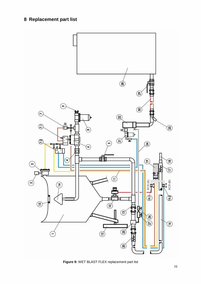
8 Replacement part list
Figure 9: WET BLAST FLEX replacement part list

17
Item Stock
no.
Description
1 JH150040 SC-2048 WIS ROH
90562D COVER FOR BLAST RECIPIENT 2040, 2048
90095A PROFILE SEAL SIMPLE
2 90743D SILENCER FOR RMS-2000
3 03371I OUTLET VALVE TLR 1”
4 99633D CHECK VALVE 11/4” WITH SEMI-CIRCLE
5 02397D BALL VALVE 11/4” WITH HANDLE
6 10711Z PILOT PRESSURE REGULATOR 11/2
7 100061 PRESSURE REGULATOR 1/4 WITH MANOMETER
7.1 99406D 3/2-WAY VALVE
7.2 99406D 3/2-WAY VALVE
8 90545D WATER SEPARATOR 11/2” HMS
9 24232D CFT MALLEABLE CAST IRON COUPLING 11/2”
10 90378D PT VALVE 11/4” / TC (blast media metering/stop valve)
11 90082D REMOTE CONTROL HOSE 5 MM
- 90079D REMOTE CONTROL HOSE 6 MM
12 90567D WHEEL FOR 2048
13 91012D CFT-50 MALLEABLE CAST IRON COUPLING WITH COARSE THREAD
14 02321D CONE P-2 WITH SHAFT
15 99157D O-RING P-5 WITH SQUARE LIP
16 04260D BLAST-HOSE 32 X 8 (20 m)
17 04127D NHP-2 NOZZLE HOLDER 32 X 8
18 92001D CTSD-X-6/50 TUNGSTEN CARBIDE NOZZLE 9.5 MM
19 99171D RLX-III-ACS DUAL-FUNCTION DEADMAN HANDLE
19.1 99172D ACS MANUAL SLIDE VALVE
19.2 99172D ACS MANUAL SLIDE VALVE
20 08413D CQP-2 COUPLING 32 X 8
21 99375D FILTER 1/4” FOR W-92 (COMPRESSED AIR-STOP-COCK (ACCESSORY) – COMPRESSED AIR CONNECTION)
22 99839D W 92 WET BLAST PUMP
23 99574D DIRT TRAP 1/2” FOR W-92
24 27233D HIGH-PRESSURE HOSE 3/8, 1.2 M WIS
25 90369D KB-52-1 WET BLAST HEAD
- 00854D SEAL KB 52
26 99917D 3/8” BALL VALVE 50 BAR
- 90371D STEEL RING FOR KB-52-1
- 90631D O-RING FOR HARD METAL RING KB-52
- 100036 WATER NOZZLE KB-52-1 WITH BORE HOLE (1 pc./hard metal ring)

18
- 90372D WATER NOZZLE KB-52-1 WITHOUT BORE HOLE (2 pcs./hard metal ring)
27 94322D NEEDLE VALVE FOR KB-52
- 94349D NOZZLE SEAL KB-52
28 27232D WATER RECIPIENT 500l WIS
29 02396D BALL VALVE 1” WITH HANDLE
30 94328A WATER SUCTION HOSE FOR KBA, PER METRE
Table 5: WET BLAST FLEX replacement parts