Status Report Westinghouse Lead Fast Reactor (Westinghouse ...
Westinghouse Electric CompanyTraveller Safety Analysis Report Rev. 12, 3/2015
Docket No. 71-9297
TABLE OF CONTENTS
3.0 THERMAL EVALUATION................................................................................................................... 3-13.1 Description of Thermal Design .................................................................................................... 3-1
3.1.1 Design Features ................................................................................................................. 3-13.1.2 Contents Decay Heat ......................................................................................................... 3-23.1.3 Summary Tables of Temperatures..................................................................................... 3-23.1.4 Summary Tables of Maximum Pressures .......................................................................... 3-3
3.2 Materials Properties and Component Specifications.................................................................... 3-33.2.1 Materials Properties ........................................................................................................... 3-33.2.2 Component Specifications ................................................................................................. 3-4A
3.3 General Considerations ................................................................................................................ 3-53.3.1 Evaluation by Analysis ...................................................................................................... 3-5
3.3.3.1 Traveller VVER .................................................................................................. 3-5A3.3.2 Evaluation by Test ............................................................................................................. 3-7
3.3.2.1 Seam Burn Test ................................................................................................... 3-73.3.2.2 Impact Limiter Burn Test.................................................................................... 3-8
3.3.3 Margins of Safety .............................................................................................................. 3-103.4 Thermal Evaluation Under Normal Conditions of Transport+ .................................................... 3-103.5 Thermal Evaluation Under Hypothetical Accident Conditions.................................................... 3-10
3.5.1 Initial Conditions ............................................................................................................... 3-133.5.2 Fire Test Conditions .......................................................................................................... 3-133.5.3 Maximum Temperatures and Pressures............................................................................. 3-133.5.4 Accident Conditions for Fissile Material Packages for Air Transport .............................. 3-14A
3.6 Appendices ................................................................................................................................... 3-153.6.1 References ......................................................................................................................... 3-15A3.6.2 Traveller Thermal Analysis ............................................................................................... 3-163.6.3 Traveller Seam Burn Tests ................................................................................................ 3-19
3.6.3.1 Test Results ......................................................................................................... 3-213.6.3.2 Conclusions ......................................................................................................... 3-25
3.6.4 Traveller Impact Limiter Burn Tests ................................................................................. 3-263.6.4.1 First Impact Limiter Burn (December 15) .......................................................... 3-283.6.4.2 Second Impact Limiter Burn (December 16)...................................................... 3-313.6.4.3 Test Conclusions ................................................................................................. 3-33
3.6.5 Traveller Certification Test Unit Burn Test ...................................................................... 3-353.6.5.1 Test Procedures and Results................................................................................ 3-40
3-i

Westinghouse Electric CompanyTraveller Safety Analysis Report Rev. 12, 3/2015
Docket No. 71-9297
LIST OF TABLES
Table 3-1 Summary Table of Temperatures for Traveller Materials............................................................ 3-2Table 3-2 Room Temperature Properties of Key Traveller Materials .......................................................... 3-4Table 3-3A Room Temperature Properties of Key Fuel Assembly Materials ................................................ 3-4Table 3-3B Room Temperature Properties of Key VVER Fuel Assembly Materials..................................... 3-4ATable 3-3C VVER Fuel Assembly vs. 17X17 XL Fuel Assembly Thermal Analysis Parameters................. 3-5ATable 3-4 Temperature Dependent Thermal Conductivity Used to Model Polyurethane Foam.................. 3-17Table 3-4A Summary of Recorded Temperatures During Burn Test.............................................................. 3-42ATable 3-5 Optical Thermometer Data Sheet (West Side, Degrees C) .......................................................... 3-45Table 3-6 Optical Thermometer Data Sheet (East Side, Degrees C)............................................................ 3-46Table 3-7 Wind Data Sheet........................................................................................................................... 3-47
3-ii

Westinghouse Electric CompanyTraveller Safety Analysis Report Rev. 9, 11/2010
Docket No. 71-9297
LIST OF FIGURES
Figure 3-1 Calculated Radial Temperature Distribution for 30 Minute Fire (800°C) ................................. 3-6
Figure 3-2 Calculated Radial Temperature Distribution for 30 Minute Fire (1000°C) ............................... 3-6
Figure 3-3 Seam Burn Test .......................................................................................................................... 3-8
Figure 3-4 December 15, Impact Limiter Burn Test.................................................................................... 3-9
Figure 3-5 Pool Fire Test Facility ................................................................................................................ 3-11
Figure 3-6 Traveller CTU During Pool Fire Test ........................................................................................ 3-12
Figure 3-7 Thermocouple Locations Measuring Fire Temperature During CTU Burn Test....................... 3-12
Figure 3-8 Temperature Strip Condition After CTU Burn Test .................................................................. 3-14
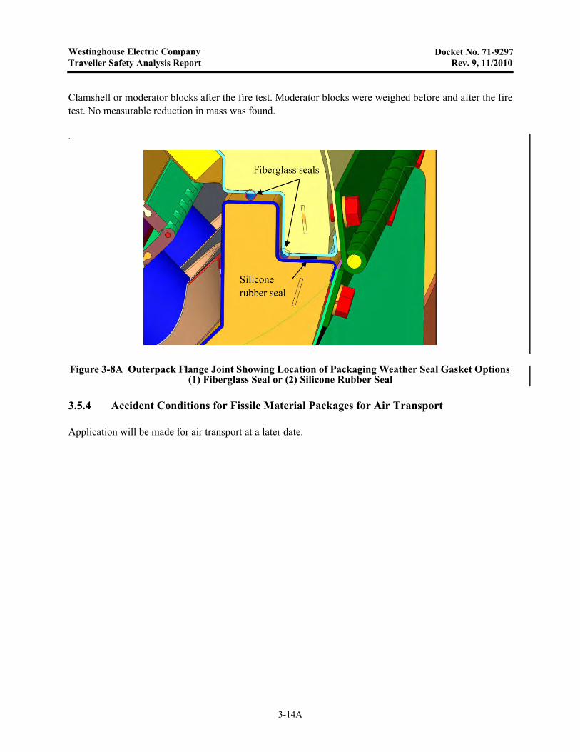
Figure 3-8A Outerpack Flange Joint Showing Location of Packaging Weather Seal Gasket Options (1) Fiberglass Seal or (2) Silicone Rubber Seal ............................................................................... 3-14A
Figure 3-9 Approach Used to Generate Analytical Model Geometry ......................................................... 3-16
Figure 3-10 Seam Burn Test Orientation ....................................................................................................... 3-20
Figure 3-11 Package Exterior Wrapped with Ceramic Fiber Insulation........................................................ 3-20
Figure 3-12 Measured Temperatures During Second Burn of the Control Section....................................... 3-21
Figure 3-13 Interior Temperature Measurements During Test of Continuous Hinge Section ...................... 3-23
Figure 3-14 Interior Temperature Measures After Test of Continuous Hinge Section ................................. 3-23
Figure 3-15 Interior Temperature Measurements During Test of Covered Moderator Section .................... 3-24
Figure 3-16 Gaps in Outerpack Bottom Seam at Covered Moderator Test Section...................................... 3-25
Figure 3-17 Thermocouple Locations in Impact Limiter............................................................................... 3-26
Figure 3-18 Thermocouple Locations in Outerpack Interior ......................................................................... 3-27
Figure 3-19 December 15, Impact Limiter Burn Test.................................................................................... 3-28
Figure 3-20 Impact Limiter Pillow Temperatures ......................................................................................... 3-29
Figure 3-21 Internal Outerpack Skin Temperatures (December 15 Burn) .................................................... 3-29
Figure 3-22 Flame Temperatures Measured by Optical Pyrometers ............................................................. 3-30
Figure 3-23 Outerpack Internals after December 15 Burn Test..................................................................... 3-30
Figure 3-24 Kaowool Layers on Outerpack Bottom Impact Limiter............................................................. 3-31
Figure 3-25 December 16 Impact Limiter Burn ............................................................................................ 3-32
Figure 3-26 Internal Outerpack Skin Temperatures (December 16 Burn) .................................................... 3-32
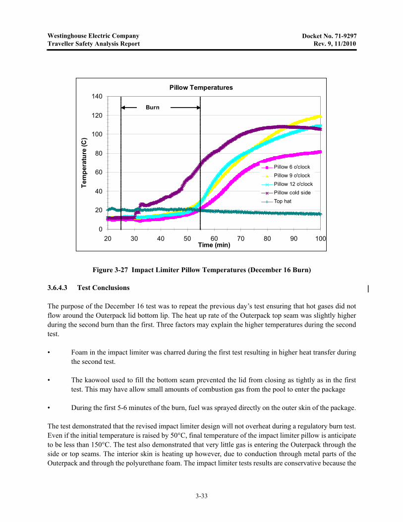
Figure 3-27 Impact Limiter Pillow Temperatures (December 16 Burn) ....................................................... 3-33
Figure 3-27A Orientation of CTU for Thermal Test ........................................................................................ 3-35
3-iii
Westinghouse Electric CompanyTraveller Safety Analysis Report Rev. 9, 11/2010
Docket No. 71-9297
LIST OF FIGURES (cont.)
Figure 3-27B Fire Fighters Standing by Fire Suppression System .................................................................. 3-35A
Figure 3-27C Approach to Suppress Pool Fire at End of Test ......................................................................... 3-35B
Figure 3-28 Traveller CTU Burn Test ........................................................................................................... 3-36
Figure 3-29 Thermocouple Locations on CTU Burn Test ............................................................................. 3-36
Figure 3-30 Polyurethane Char in Outerpack Seam After Burn Test ............................................................ 3-37
Figure 3-31 Brown Polyurethane Residue Inside Outerpack After Burn Test .............................................. 3-37
Figure 3-32 Test Stand for Fire Test .............................................................................................................. 3-39
Figure 3-33 Test Setup with Steel Diffuser Plates ......................................................................................... 3-39
Figure 3-34 Test Article Under Tent to Maintain Temperature Overnight ................................................... 3-40
Figure 3-35 Overnight Temperatures on East Side of Test Article ............................................................... 3-41
Figure 3-36 Overnight Temperatures on West Side of Test Article .............................................................. 3-41
Figure 3-37 Fire Temperatures Measured at the Corners of the Pool........................................................... 3-42B
Figure 3-38 Data from Direction Flame Thermometers (DFTs) ................................................................... 3-43
Figure 3-39 Skin Temperature Data from East Side of CTU......................................................................... 3-43
Figure 3-40 Skin Temperature Data from West Side of CTU ....................................................................... 3-44
Figure 3-41 Fire Temperature Data from East Side of CTU ......................................................................... 3-44
Figure 3-42 Fire Temperature Data from West Side of CTU ........................................................................ 3-45
Figure 3-43 Location of Possible Combustion of Moderator ........................................................................ 3-48
Figure 3-44 Localized Melt Spot in Lid Moderator Block ............................................................................ 3-48
Figure 3-45 Location and Indicated Temperatures of Temperature Strip Sets .............................................. 3-49
Figure 3-46 Temperature Strip Set After Fire Test ........................................................................................ 3-50
3-iv

Westinghouse Electric CompanyTraveller Safety Analysis Report Rev. 10, 9/2013
Docket No. 71-9297
3.0 THERMAL EVALUATION
The Traveller series packages are limited to use for transporting unirradiated, low enriched uranium, nuclearreactor core assemblies. There is no packaging design feature for heat removal because the contents doesnot contain heat generating radioactive material. The use of polyethylene as a moderator requires controlledheat-up during accident conditions, to prevent loss of hydrogen within the moderator.
3.1 DESCRIPTION OF THERMAL DESIGN
3.1.1 Design Features
The Traveller series packages, as described in section 2, utilize an aluminum Clamshell to contain a singleunirradiated nuclear fuel assembly. The Clamshell is mounted within a cylindrical Outerpack fabricatedfrom 304 stainless steel and flame retardant polyurethane foam. The stainless steel/foam sandwich providesthermal insulation during hypothetical fire conditions. Most of the heat capacity is within the Outerpack,provided by the polyethylene moderator, the aluminum Clamshell and the fuel assembly itself reducing thepeak temperatures within the package.
The fuel rods, that contain the radioactive material, are designed to withstand temperatures of 1204°C(2200°F) without substantial damage. The primary temperature limitation is the polyethylene moderatorlocated on the inside surface of the Outerpack. Polyethylene was selected because it retains its chemicalcomposition and therefore its hydrogen content past melt temperature (between 120° and 137°C). Becauseof its very high viscosity, it will not flow significantly and will not change chemical composition unlesssignificant amounts of high temperature oxygen are present (320-360°C).
The design and test strategy employed for the Traveller was to utilize design approaches that had previouslypassed the thermal test requirements. A review of previous designs and associated test results led to theselection of a stainless steel/polyurethane sandwich for the Outerpack. Based on this design approach,scoping tests and thermal analysis were performed to size the Outerpack structure. These analyses showedthat sufficient polyurethane was incorporated to effectively insulate the interior of the Outerpack. Asdescribed in section 3.3.1 below, anticipated heat transfer due to conduction and radiation was so low thatpeak temperatures within the Outerpack would be below the melt temperature of the polyethylene and wellbelow its ignition temperature. The primary concern was hot gas flow into the interior of the Outerpack. Ifboth inner and outer skins of the Outerpack are ripped or if the seam between the Outerpack door and baseare opened during the drop tests, hot gas from the fire could flow through the Outerpack significantlyincreasing its temperature. The Outerpack was made sufficiently robust that the defined drops did not createair infiltration paths within the Outerpack.
During the development process, three Traveller test articles were built. All were subjected to drop testing.Afterwards, these units were subjected to multiple burn tests. The information obtained during tests wasincorporated into the final design of the Traveller Certification Test Unit (CTU). The CTU was subjected todrop testing as described above (Section 2.12.4). The CTU was then transported to Columbia, SC where itwas burned in accordance with 10CFR71.73(c)(4) and TS-R-1, paragraph 728(a).
3-1
Westinghouse Electric CompanyTraveller Safety Analysis Report Rev. 9, 11/2010
Docket No. 71-9297
The package survived the test with maximum internal temperatures less than 180°C. The results of this testare described in section 3.5 and appendix 3.6.4.
3.1.2 Contents Decay Heat
Decay heat and radioactivity of the contents are not applicable for this package type.
3.1.3 Summary Tables of Temperatures
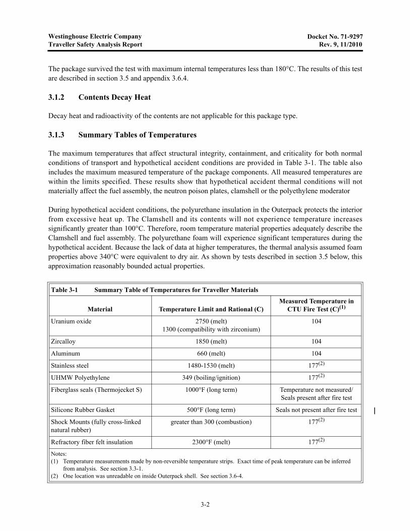
The maximum temperatures that affect structural integrity, containment, and criticality for both normalconditions of transport and hypothetical accident conditions are provided in Table 3-1. The table alsoincludes the maximum measured temperature of the package components. All measured temperatures arewithin the limits specified. These results show that hypothetical accident thermal conditions will notmaterially affect the fuel assembly, the neutron poison plates, clamshell or the polyethylene moderator
During hypothetical accident conditions, the polyurethane insulation in the Outerpack protects the interiorfrom excessive heat up. The Clamshell and its contents will not experience temperature increasessignificantly greater than 100°C. Therefore, room temperature material properties adequately describe theClamshell and fuel assembly. The polyurethane foam will experience significant temperatures during thehypothetical accident. Because the lack of data at higher temperatures, the thermal analysis assumed foamproperties above 340°C were equivalent to dry air. As shown by tests described in section 3.5 below, thisapproximation reasonably bounded actual properties.
Table 3-1 Summary Table of Temperatures for Traveller Materials
Material Temperature Limit and Rational (C)Measured Temperature in
CTU Fire Test (C)(1)
Uranium oxide 2750 (melt)1300 (compatibility with zirconium)
104
Zircalloy 1850 (melt) 104
Aluminum 660 (melt) 104
Stainless steel 1480-1530 (melt) 177(2)
UHMW Polyethylene 349 (boiling/ignition) 177(2)
Fiberglass seals (Thermojecket S) 1000°F (long term) Temperature not measured/Seals present after fire test
Silicone Rubber Gasket 500°F (long term) Seals not present after fire test
Shock Mounts (fully cross-linked natural rubber)
greater than 300 (combustion) 177(2)
Refractory fiber felt insulation 2300°F (melt) 177(2)
Notes:(1) Temperature measurements made by non-reversible temperature strips. Exact time of peak temperature can be inferred
from analysis. See section 3.3-1. (2) One location was unreadable on inside Outerpack shell. See section 3.6-4.
3-2
Westinghouse Electric CompanyTraveller Safety Analysis Report Rev. 12, 3/2015
Docket No. 71-9297
3.1.4 Summary Tables of Maximum Pressures
The Traveller Outerpack surrounds the Clamshell and fuel assembly. It has silicone rubber or fiberglassseals to prevent rain, dirt, dust and spray from entering the package. The seals are not continuous, however,to avoid producing an air-tight seal. The Traveller Clamshell is not air tight and cannot maintain a differentpressure than the air surrounding it. The double wall Traveller Outerpack also incorporates acetate sealplugs that melt in the event of a fire allowing decomposition products from the polyurethane insulate to ventto the outside air. Therefore, the Traveller interior pressure will always maintain itself in approximateequilibrium with external air pressure.
3.2 MATERIALS PROPERTIES AND COMPONENT SPECIFICATIONS
3.2.1 Materials Properties
The Traveller package series is fabricated primarily from four materials: 304 stainless steel,6005 aluminum, Ultra-High Molecular Weight (UHMW) polyethylene, and flame retardant polyurethanefoam. The Outerpack is fabricated from stainless steel and the polyurethane foam. The interior Clamshellholding the fuel assembly is fabricated from aluminum. The polyethylene is used as a neutron moderatorand is located on the inside walls of the Outerpack, between the Outerpack and Clamshell. The importantroom temperature material properties are provided in Table 3-2.
The melt temperature of the polyurethane foam is not provided because it is a thermoset material thatdecomposes before melting. The urethane foam selected for use will be a fire retardant foam that, whenheated above 204.4°C, produces an intumenscent char that seals voids and continues to provide insulation.This process is endothermic and produces gasses that must be vented. Vent plugs are placed along the lengthof the package to provide this venting. All Outerpack components containing polyurethane foam will haveat least one vent plug.
The fuel assembly significantly affects the response of the overall package during a hypothetical fire.Because the fuel assembly may account for as much as 40% of the total package weight, the thermalcapacity of the fuel assembly has a significant effect interior temperature. Key materials for the 17x17 XLfuel assembly to be shipped in the Traveller XL package is shown in Table 3-3A. Key materials for theVVER fuel assembly to be shipped in the Traveller VVER package is shown in Table 3-3B.
Traveller VVER requires a thermal evaluation to ensure the package design and fissile contents are in a safecondition following normal and hypothetical accident conditions. Structural evaluations (Chapter 2) havedemonstrated that the expected mechanical damage is bounded by the Traveller XL. Since Traveller VVERis a similar fresh fuel shipping package with respect to expected mechanical and thermal performance to aTraveller XL, the Traveller XL thermal methodology forms the basis for Traveller VVER evaluation.Section 3.3.1.1 provides the technical justification for use of Traveller XL thermal analysis.
3-3

Westinghouse Electric CompanyTraveller Safety Analysis Report Rev. 12, 3/2015
Docket No. 71-9297
Table 3-2 Room Temperature Properties of Key Traveller Materials
Material Density Melt Temp Conductivity Specific Heat
304 Stainless Steel 8.3 g/cc.29 lb/in3
1400-1455°C2550-2650°F
14.2 W/m-K8.2 BTU/hr-ft-F
0.5 J/g-°C0.12 BTU/lb-°F
6005 Aluminum 2.8 g/cc.098 lb/in3
582-652°C1080-1210°F
167 W/m-K96.1 BTU/hr-ft-F
0.88 J/g-°C0.21 BTU/lb-°F
UHMW polyethylene .932-.945 g/cc.0337 - .0341 lb/in3
125-138°C257-280°F
0.42 W/m-K.24 BTU/hr-ft-F
2.2 J/g-°C0.526 BTU/lb-°F
Polyurethane Foam 0.166 g/cc.0058 lb/in3
NA 0.041 W/m-K.023 BTU/hr-ft-F
1.15 J/g-°C0.275 BTU/lb-°F
Fiberglass seals (Thermojecket S)
NA(2) 538°C(1)
1000°FNA(2) NA(2)
Silicone rubber gasket NA(2) -73 to 250°C(1)
-100 to 500°FNA(2) NA(2)
Refractory fiber felt insulation
0.097 g/cc.0035 lb/in3
1260°C2300°F
.06 W/m-K
.034 BTU/hr-ft-F1.0 J/g-°C0.239 BTU/lb-°F
Notes:(1) Temperature range that the gasket material and adhesive will withstand.(2) Packaging weather gasket is to keep dust, dirt and spray from getting inside the Outerpack.
Table 3-3A Room Temperature Properties of Key Fuel Assembly Materials
Material Mass in FA Melt Temp Conductivity Specific Heat
304 Stainless Steel 22 kg49 lb
1400-1455°C2550-2650°F
14.2 W/m-K8.2 BTU/hr-ft-F
0.5 J/g-°C0.12 BTU/lb-°F
Inconel 2.7 kg6 lb
1354-1413°C2470-2580°F
14.9 W/m-K8.6 BTU/hr-ft-F
0.44 J/g-°C0.106 BTU/lb-°F
Zircalloy 4 150 kg330 lb
1850°C3360°F
21.5 W/m-K12.4 BTU/hr-ft-F
0.285 J/g-°C0.0681 BTU/lb-°F
Uranium dioxide 608.3 kg1341 lb
2750°C4982°F
5.86 W/m-K3.39 BTU/hr-ft-F
0.237 J/g-°C0.0565 BTU/lb-°F
3-4
Westinghouse Electric CompanyTraveller Safety Analysis Report Rev. 12, 3/2015
Docket No. 71-9297
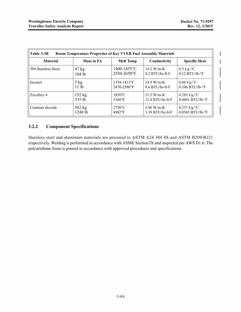
3.2.2 Component Specifications
Stainless steel and aluminum materials are procured to ASTM A24 304 SS and ASTM B209/B221respectively. Welding is performed in accordance with ASME Section IX and inspected per AWS D1.6. Thepolyurethane foam is poured in accordance with approved procedures and specifications.
Table 3-3B Room Temperature Properties of Key VVER Fuel Assembly Materials
Material Mass in FA Melt Temp Conductivity Specific Heat
304 Stainless Steel 47 kg104 lb
1400-1455°C2550-2650°F
14.2 W/m-K8.2 BTU/hr-ft-F
0.5 J/g-°C0.12 BTU/lb-°F
Inconel 5 kg11 lb
1354-1413°C2470-2580°F
14.9 W/m-K8.6 BTU/hr-ft-F
0.44 J/g-°C0.106 BTU/lb-°F
Zircalloy 4 152 kg335 lb
1850°C3360°F
21.5 W/m-K12.4 BTU/hr-ft-F
0.285 J/g-°C0.0681 BTU/lb-°F
Uranium dioxide 562 kg1240 lb
2750°C4982°F
5.86 W/m-K3.39 BTU/hr-ft-F
0.237 J/g-°C0.0565 BTU/lb-°F
3-4A

Westinghouse Electric CompanyTraveller Safety Analysis Report Rev. 10, 9/2013
Docket No. 71-9297
3.3 GENERAL CONSIDERATIONS
Thermal evaluations of the Traveller were performed by analysis and actual test. The Traveller packageutilizes a double wall, insulated, Outerpack to protect an interior box (Clamshell) containing a fuel assemblyand blocks of polyethylene moderator. Because of the large length to diameter ratio (8.8), heat transport inmost of the package is primarily radial. The thermal analysis performed examined this heat transport path.The seam burn tests, examined radial heat flow with prototypical gas infiltration through the Outerpackseams. The impact limiter burn tests, examined and measured the heat transport through the ends of thepackage. The final QTU burn test combined all of the possible heat transport mechanism and demonstratedthe suitability of the design.
3.3.1 Evaluation by Analysis
The thermal model of the Traveller package was created to examine the response to the hypothetical fireaccident conditions described in 10 CFR 71 and IAEA Regulations for the Safe Transport of RadioactiveMaterial, Section VII-728. This analysis was performed to bound the anticipated response and was done byanalyzing the response of the package at 800°C external conditions with a fire emissivity of 0.9 and apackage emissivity of 0.8 as defined by 10CFR71.73. The analysis was also performed assuming an averagefire temperature of 1000°C anticipated during an actual burn test. The analytical burn model did not includepotential damage to the Outerpack because:
• Minimum damage was anticipated after drop test
• The anticipated minor damage would not have a significant impact of global performance
• The combined uncertainty of the package damage combined with uncertainty in modeling gas flowpatterns around the package made a detailed thermal analysis undesirable.
The analysis results show that the outer skin of the package quickly rises to thermal equilibrium with thefire. The internal components heat up more slowly due to the insulation capability of the polyurethane foambetween the inner and outer shell of the Outerpack. Fuel and Clamshell temperatures increase byapproximately 50°C and are well within acceptable levels, see Figure 3-1 and Figure 3-2. This analysis isdescribed in greater detail in appendix 3.6.1.
3-5
Westinghouse Electric CompanyTraveller Safety Analysis Report Rev. 12, 3/2015
Docket No. 71-9297
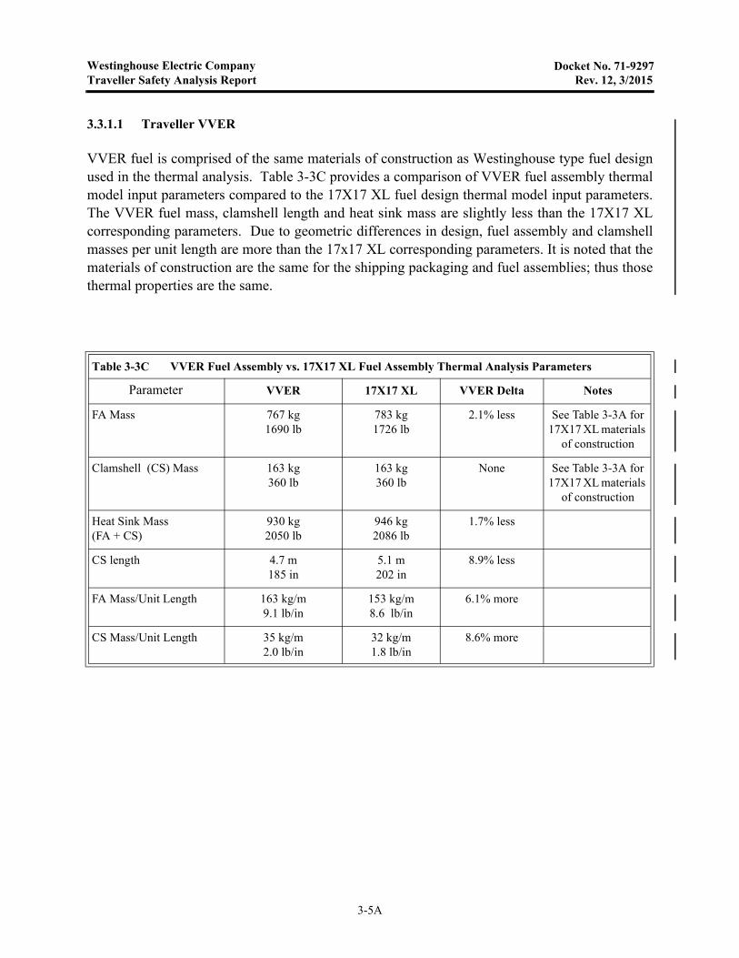
3.3.1.1 Traveller VVER
VVER fuel is comprised of the same materials of construction as Westinghouse type fuel designused in the thermal analysis. Table 3-3C provides a comparison of VVER fuel assembly thermalmodel input parameters compared to the 17X17 XL fuel design thermal model input parameters.The VVER fuel mass, clamshell length and heat sink mass are slightly less than the 17X17 XLcorresponding parameters. Due to geometric differences in design, fuel assembly and clamshellmasses per unit length are more than the 17x17 XL corresponding parameters. It is noted that thematerials of construction are the same for the shipping packaging and fuel assemblies; thus thosethermal properties are the same.
Table 3-3C VVER Fuel Assembly vs. 17X17 XL Fuel Assembly Thermal Analysis Parameters
Parameter VVER 17X17 XL VVER Delta Notes
FA Mass 767 kg1690 lb
783 kg1726 lb
2.1% less See Table 3-3A for 17X17 XL materials
of construction
Clamshell (CS) Mass 163 kg360 lb
163 kg360 lb
None See Table 3-3A for 17X17 XL materials
of construction
Heat Sink Mass (FA + CS)
930 kg2050 lb
946 kg2086 lb
1.7% less
CS length 4.7 m185 in
5.1 m202 in
8.9% less
FA Mass/Unit Length 163 kg/m9.1 lb/in
153 kg/m8.6 lb/in
6.1% more
CS Mass/Unit Length 35 kg/m2.0 lb/in
32 kg/m1.8 lb/in
8.6% more
3-5A
Westinghouse Electric CompanyTraveller Safety Analysis Report Rev. 12, 3/2015
Docket No. 71-9297
The thermal model was re-run using the fuel assembly and Clamshell parameters. There was no significantchange in the Traveller VVER model's predicted maximum temperature of 108°C (versus 106°C forTraveller XL) for either the 800°C or 1000°C flame temperatures. Thus, Figures 3-1 and 3-2 also representthe predicted VVER maximum temperatures.
Traveller XL thermal analysis consisted of a smeared model based upon simplified geometry. The analysisillustrated the fundamental thermal mechanisms involved and provides a general expected package responseassuming no significant hot gas infusion or significant geometry changes (from the drop tests). The thermalanalysis was utilized to ensure that peak polyethylene moderator temperatures were below the material'smelt temperature. Despite fundamental limitations (i.e. response assuming no hot gas infusion or significantgeometry changes), the analysis model demonstrated close agreement to the actual seam burn fire tests (acontinuous Outerpack hinge). The internal predicted temperature rise predicted by analysis was 50°C,which is in excellent agreement with the measured temperature rise of 60°C for the continuous hinge burntesting. The analysis predicted a maximum temperature of 106°C on the moderator cover, as compared toan average measured temperature (of the CTU) of 143°C.
The Traveller XL thermal analysis inputs to the smeared model represent the Traveller VVER. Theremaining thermal sections; 3.3.2 and 3.3.3 provide Traveller XL evaluation by testing. Sections 3.4 throughand including 3.6 provide the Traveller detailed thermal analysis and testing which demonstrated theTraveller XL's thermal design acceptability.
It is concluded that the Traveller VVER, by virtue of its fundamental design similarities to the Traveller XL,and results of the thermal analysis, offers an acceptable thermal design. Hereafter, Traveller thermalevaluations and testing represent the bounding Traveller XL thermal evaluations and testing applicable toTraveller VVER.
3-5B

Westinghouse Electric CompanyTraveller Safety Analysis Report Rev. 0, 3/2004
Docket No. 71-9297
Figure 3-1 Calculated Radial Temperature Distribution for 30 Minute Fire (800°C)
Figure 3-2 Calculated Radial Temperature Distribution for 30 Minute Fire (1000°C)
Temperature Distribution - 30 min Burn, 800 C
0
100
200
300
400
500
600
700
800
900
0 20 40 60 80 100 120
Time (min)
Te
mp
era
ture
(C
)
FA innerClamPoly innerPoly midPoly outerFoam innerFoam 0.8"Foam 1.6"Foam 2.4"Foam OD
Temperature Distribution - 30 min Burn, 1000 C
0
100200
300400
500600
700800
9001000
1100
0 20 40 60 80 100 120Time (min)
Te
mp
era
ture
(C
)
FA innerClamPoly innerPoly midPoly outerFoam innerFoam 0.8"Foam 1.6"Foam 2.4"Foam OD
3-6

Westinghouse Electric CompanyTraveller Safety Analysis Report Rev. 0, 3/2004
Docket No. 71-9297
3.3.2 Evaluation by Test
Traveller performance under hypothetical accident conditions specified in 10CFR71.73 (c) and IAEARegulations for the Safe Transport of Radioactive Material, Section VII-728 was initially calculated usingthe SCALE 4.4 thermal analysis code. The performance was subsequently demonstrated in a series of partialburn tests exposing selective portions of a full-scale package to pool fire conditions exceeding thehypothetical accident conditions. Finally, a full scale package was subjected to a full scale, fully engulfing,pool fire exceeding hypothetical accident conditions.
Two separate partial burn tests were performed to verify the final Traveller design. The first was the seamburn test. This test was designed to simulate the flow of hot gas through the Outerpack seams at the hingedjoint between the Outerpack base and the Outerpack door and to measure the resulting heat transfer. Thesecond, was the impact limiter burn test. This test subjected the end of a Traveller package to pool fireconditions to measure heat transfer at the package ends. These partial burn tests were then followed by aburn test of the qualification test article. This test, which followed the regulatory drop tests, completelyimmersed the full scale test unit in a pool fire for more than 30 minutes in flames significantly hotter than800°C.
3.3.2.1 Seam Burn Test
The seam burn tests were designed to measure performance of different design approaches of protectingpolyethylene moderator from excessive heat during the hypothetical fire conditions. Previous burn tests hadrevealed a tendency for package structures to deform in pool fires potentially allowing hot gasses to enterthe package. The tests, performed in a previously burned package with large gaps left between the upper andlower Outerpack to allow hot gases to enter the package. One section, used as a control, had no protectionfor interior structures. The second section covered the Outerpack seam with stainless steel hinges to modela design with essentially continuous hinges. The third section used 26 gage stainless steel to cover themoderator blocks. The steel cover sheet was stitch welded in place, leaving gaps for combustion air to enter.The test approach is described in appendix 3.6.2
The first burn was of the control section. During the 30 minute burn, internal temperatures rose within thetest section throughout the test due to the gap deliberately left in the seam between Outerpack base and lidPeak internal temperatures over 500°C were observed, Figure 3-3.
The second test burn was of the section protected with essentially continuous hinge material. This sectionhad a similar gap between the Outerpack base and lid, but gas flow through the package was minimized bythe hinge sections. This burn lasted for 35 minutes with internal temperatures rising to 75°C (from an initialtemperature of 35°C). After the burn was completed, interior temperatures continued to rise, peaking after30 minutes at approximately 100°C.
The third test section was burned for 35 minutes as well. The internal temperatures measured showtemperatures rose at a much higher rate than in the second test. This was expected because of the large gapesin the Outerpack seam (varying between 0.5 and 1.5 inches at the bottom seam). One thermocouple showedtemperature at the bottom moderator blocks rose above 350°C within 25 minutes after the start of the burn.
3-7
Westinghouse Electric CompanyTraveller Safety Analysis Report Rev. 0, 3/2004
Docket No. 71-9297
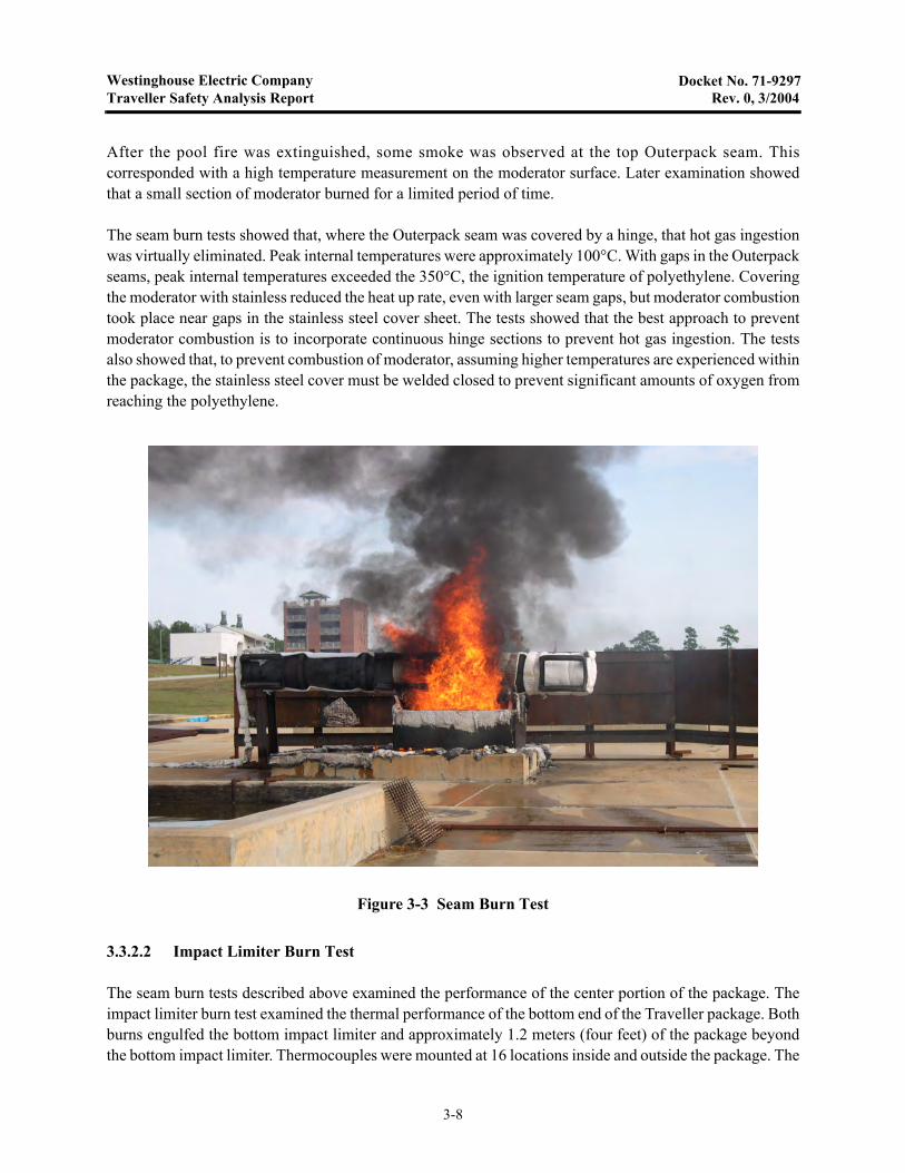
After the pool fire was extinguished, some smoke was observed at the top Outerpack seam. Thiscorresponded with a high temperature measurement on the moderator surface. Later examination showedthat a small section of moderator burned for a limited period of time.
The seam burn tests showed that, where the Outerpack seam was covered by a hinge, that hot gas ingestionwas virtually eliminated. Peak internal temperatures were approximately 100°C. With gaps in the Outerpackseams, peak internal temperatures exceeded the 350°C, the ignition temperature of polyethylene. Coveringthe moderator with stainless reduced the heat up rate, even with larger seam gaps, but moderator combustiontook place near gaps in the stainless steel cover sheet. The tests showed that the best approach to preventmoderator combustion is to incorporate continuous hinge sections to prevent hot gas ingestion. The testsalso showed that, to prevent combustion of moderator, assuming higher temperatures are experienced withinthe package, the stainless steel cover must be welded closed to prevent significant amounts of oxygen fromreaching the polyethylene.
3.3.2.2 Impact Limiter Burn Test
The seam burn tests described above examined the performance of the center portion of the package. Theimpact limiter burn test examined the thermal performance of the bottom end of the Traveller package. Bothburns engulfed the bottom impact limiter and approximately 1.2 meters (four feet) of the package beyondthe bottom impact limiter. Thermocouples were mounted at 16 locations inside and outside the package. The
Figure 3-3 Seam Burn Test
3-8
Westinghouse Electric CompanyTraveller Safety Analysis Report Rev. 0, 3/2004
Docket No. 71-9297
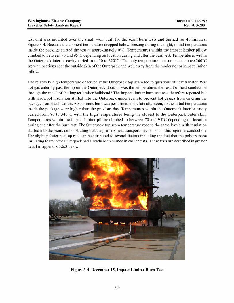
test unit was mounted over the small weir built for the seam burn tests and burned for 40 minutes,Figure 3-4. Because the ambient temperature dropped below freezing during the night, initial temperaturesinside the package started the test at approximately 0°C. Temperatures within the impact limiter pillowclimbed to between 70 and 95°C depending on location during and after the burn test. Temperatures withinthe Outerpack interior cavity varied from 50 to 320°C. The only temperature measurements above 200°Cwere at locations near the outside skin of the Outerpack and well away from the moderator or impact limiterpillow.
The relatively high temperature observed at the Outerpack top seam led to questions of heat transfer. Washot gas entering past the lip on the Outerpack door, or was the temperatures the result of heat conductionthrough the metal of the impact limiter bulkhead? The impact limiter burn test was therefore repeated butwith Kaowool insulation stuffed into the Outerpack upper seam to prevent hot gasses from entering thepackage from that location. A 30 minute burn was performed in the late afternoon, so the initial temperaturesinside the package were higher than the previous day. Temperatures within the Outerpack interior cavityvaried from 80 to 340°C with the high temperatures being the closest to the Outerpack outer skin.Temperatures within the impact limiter pillow climbed to between 70 and 95°C depending on locationduring and after the burn test. The Outerpack top seam temperature rose to the same levels with insulationstuffed into the seam, demonstrating that the primary heat transport mechanism in this region is conduction.The slightly faster heat up rate can be attributed to several factors including the fact that the polyurethaneinsulating foam in the Outerpack had already been burned in earlier tests. These tests are described in greaterdetail in appendix 3.6.3 below.
Figure 3-4 December 15, Impact Limiter Burn Test
3-9
Westinghouse Electric CompanyTraveller Safety Analysis Report Rev. 10, 9/2013
Docket No. 71-9297
3.3.3 Margins of Safety
The Traveller protects its contents with a polyurethane insulated, double walled, stainless steel Outerpack.This Outerpack provides sufficient insulation to prevent significant heat conduction and maintain lowinterior temperatures during a hypothetical fire accident. The Outerpack also incorporates design featuresthat prevent convective heat transfer. The tests described in 3.3.2 above, identified features (continuoushinge lengths and a large lip over the bottom seam) that prevent hot gases from entering the Outerpackseams. The results of these tests, as described in sections 3.5.2 and appendices 3.6.3 and 3.6.4 show thatinternal temperatures remain low when the Outerpack seams are adequately protected. These features wereincorporated into the CTU test article and the production design. When the CTU was tested, significantmargins of safety were observed as illustrated by Table 3-1 above. The most temperature sensitivecomponent, the polyethylene moderator blocks, have an additional level of protection. The blocks are sealedby stainless steel cover sheets and are insulated at the ends. In the event that local conditions exceed thecombustion temperature of the polyethylene, the moderator is protected by an insulating air gap (andrefractory fiber felt insulation at the ends). Additionally, the moderator is isolated from oxygen preventingsignificant combustion.
3.4 THERMAL EVALUATION UNDER NORMAL CONDITIONS OF TRANSPORT+
The package will only be used to ship non-irradiated nuclear fuel. The contents contains no heat generatingradioactive material. Therefore, the surface temperature of the package will not rise above ambienttemperatures. As such, there is no need to evaluate by analysis or perform tests to demonstrate themaximum package surface temperature. All materials used within the Traveller package retain their desiredproperties over the entire range of possible ambient temperatures. The package is not hermetically sealedallowing interior pressure to adjust with changes in elevation and allowing expansion/contraction of internalair during temperature changes.
3.5 THERMAL EVALUATION UNDER HYPOTHETICAL ACCIDENT CONDITIONS
The primary verification of the Traveller’s performance in a hypothetical accident was demonstrated in theburn test of a full-scale package loaded with a simulated fuel assembly. This unit was identified as thecertification test unit (CTU). According to 10 CFR71.73 “Thermal. Exposure of the specimen fullyengulfed, except for a simple support system, in a hydrocarbon fuel/air fire of sufficient extent, and insufficiently quiescent ambient conditions, to provide an average emissivity coefficient of at least 0.9, withan average flame temperature of at least 800ºC (1475ºF) for a period of 30 minutes, or any other thermaltest that provides the equivalent total heat input to the package and which provides a time averagedenvironmental temperature of 800ºC. The fuel source must extend horizontally at least 1 m (40 in), but maynot extend more than 3 m (10 ft), beyond any external surface of the specimen, and the specimen must bepositioned 1 m (40 in) above the surface of the fuel source. For purposes of calculation, the surfaceabsorptivity coefficient must be either that value which the package may be expected to possess if exposedto the fire specified or 0.8, whichever is greater; and the convective coefficient must be that value whichmay be demonstrated to exist if the package were exposed to the fire specified. Artificial cooling may notbe applied after cessation of external heat input, and any combustion of materials of construction, must beallowed to proceed until it terminates naturally.” (The IAEA Regulations for the Safe Transport ofRadioactive Material, Section VII-728 have similar specifications.)
3-10
Westinghouse Electric CompanyTraveller Safety Analysis Report Rev. 0, 3/2004
Docket No. 71-9297
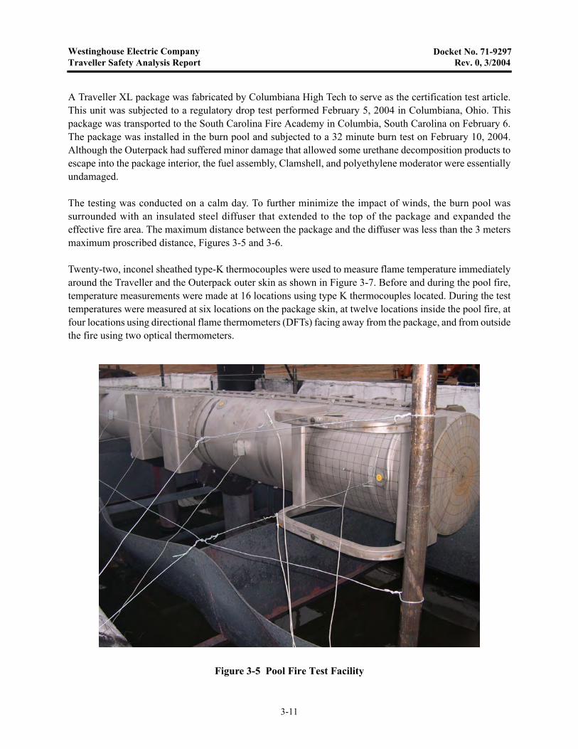
A Traveller XL package was fabricated by Columbiana High Tech to serve as the certification test article.This unit was subjected to a regulatory drop test performed February 5, 2004 in Columbiana, Ohio. Thispackage was transported to the South Carolina Fire Academy in Columbia, South Carolina on February 6.The package was installed in the burn pool and subjected to a 32 minute burn test on February 10, 2004.Although the Outerpack had suffered minor damage that allowed some urethane decomposition products toescape into the package interior, the fuel assembly, Clamshell, and polyethylene moderator were essentiallyundamaged.
The testing was conducted on a calm day. To further minimize the impact of winds, the burn pool wassurrounded with an insulated steel diffuser that extended to the top of the package and expanded theeffective fire area. The maximum distance between the package and the diffuser was less than the 3 metersmaximum proscribed distance, Figures 3-5 and 3-6.
Twenty-two, inconel sheathed type-K thermocouples were used to measure flame temperature immediatelyaround the Traveller and the Outerpack outer skin as shown in Figure 3-7. Before and during the pool fire,temperature measurements were made at 16 locations using type K thermocouples located. During the testtemperatures were measured at six locations on the package skin, at twelve locations inside the pool fire, atfour locations using directional flame thermometers (DFTs) facing away from the package, and from outsidethe fire using two optical thermometers.
Figure 3-5 Pool Fire Test Facility
3-11

Westinghouse Electric CompanyTraveller Safety Analysis Report Rev. 0, 3/2004
Docket No. 71-9297
Figure 3-6 Traveller CTU During Pool Fire Test
Figure 3-7 Thermocouple Locations Measuring Fire Temperature During CTU Burn Test
20 in
51 in above pool
100 in 60 in
36 in
20 in
51 in above pool
100 in 60 in
36 in
20 in
51 in above pool
100 in
20 in
60 in
36 in
N E
TCs attached 8"from end of package
NW upperand lowerTCs
Directional FlameThermometer(6)
3-12

Westinghouse Electric CompanyTraveller Safety Analysis Report Rev. 10, 9/2013
Docket No. 71-9297
3.5.1 Initial Conditions
The package was covered with a canvas tent approximately 16 hours before the burn test. Two 44 kWth(150,000 BTU/hr) kerosene heaters were used, alternately, to maintain air temperature within the tent toabove 37°C. The heaters were secured and the tent removed approximately 75 minutes before the beginningof the fire test. Air temperature around the package at this time averaged at 50°C (122°F). The airtemperature and outside surface temperature dropped to approximately 5°C (41°F). Additional informationcan be found in appendix 3.6-4.
3.5.2 Fire Test Conditions
The CTU burn test was performed on a cool, calm, lightly overcast morning. The test article was located ona stand in a water pool. Fuel was pumped into manifolds under the surface of the pool to provide an evendistribution of fuel for the pool fire. Approximately one minute after the fuel on the surface of the pool wasignited, the test article was completely engulfed. The fuel system continued to pump fuel into the fire until32 minutes after the pool was lit. The pool fire was extinguished approximately one minute later. Firetemperatures were measured using four directional flame thermometers (DFTs) and 12 thermocouplessuspended in the fire 0.9 m (3 feet) from the surface of the package. The 30 minute average temperaturesmeasured by the DFTs were 833°C (1531°F). The 39 minute average temperature measured by thethermocouples suspended in the fire was 859°C (1578°F). Two, hand-held, optical thermometers thatmeasured flame temperature from outside the pool supplemented these measurements. The averagereadings made with these thermometers was 958°C (1757°F).
3.5.3 Maximum Temperatures and Pressures
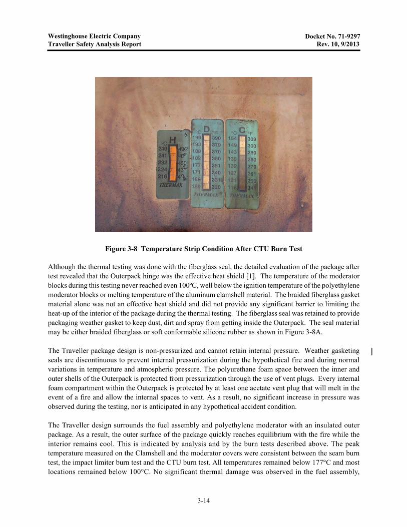
Temperatures were measured on the CTU Outerpack outer skin using six type K thermocouples, attachedby screws. These thermocouples were located as shown in Figure 3-7 above. The 30 minute averagetemperature measured by these thermocouples was 904°C (1659°F). Temperatures inside the CTUOuterpack were measured using 13 sets of non-reversible temperature strips. One set on the inner stainlesssteel skin covering the Outerpack lid moderator was unreadable. All of the remaining temperature strips onthe Outerpack lid recorded temperatures of 177°C (351°F) or below. Temperatures on the inside surface ofthe top and bottom impact limiters were 116 (241°F) and 149°C (300°F) respectively. Temperatures insidethe Clamshell were below 104°C (219°F). An example of the temperature strip sets attached to theOuterpack lid moderator cover sheets is shown in Figure 3-8.
3-13
Westinghouse Electric CompanyTraveller Safety Analysis Report Rev. 10, 9/2013
Docket No. 71-9297
Although the thermal testing was done with the fiberglass seal, the detailed evaluation of the package aftertest revealed that the Outerpack hinge was the effective heat shield [1]. The temperature of the moderatorblocks during this testing never reached even 100ºC, well below the ignition temperature of the polyethylenemoderator blocks or melting temperature of the aluminum clamshell material. The braided fiberglass gasketmaterial alone was not an effective heat shield and did not provide any significant barrier to limiting theheat-up of the interior of the package during the thermal testing. The fiberglass seal was retained to providepackaging weather gasket to keep dust, dirt and spray from getting inside the Outerpack. The seal materialmay be either braided fiberglass or soft conformable silicone rubber as shown in Figure 3-8A.
The Traveller package design is non-pressurized and cannot retain internal pressure. Weather gasketingseals are discontinuous to prevent internal pressurization during the hypothetical fire and during normalvariations in temperature and atmospheric pressure. The polyurethane foam space between the inner andouter shells of the Outerpack is protected from pressurization through the use of vent plugs. Every internalfoam compartment within the Outerpack is protected by at least one acetate vent plug that will melt in theevent of a fire and allow the internal spaces to vent. As a result, no significant increase in pressure wasobserved during the testing, nor is anticipated in any hypothetical accident condition.
The Traveller design surrounds the fuel assembly and polyethylene moderator with an insulated outerpackage. As a result, the outer surface of the package quickly reaches equilibrium with the fire while theinterior remains cool. This is indicated by analysis and by the burn tests described above. The peaktemperature measured on the Clamshell and the moderator covers were consistent between the seam burntest, the impact limiter burn test and the CTU burn test. All temperatures remained below 177°C and mostlocations remained below 100°C. No significant thermal damage was observed in the fuel assembly,
Figure 3-8 Temperature Strip Condition After CTU Burn Test
3-14
Westinghouse Electric CompanyTraveller Safety Analysis Report Rev. 9, 11/2010
Docket No. 71-9297
Clamshell or moderator blocks after the fire test. Moderator blocks were weighed before and after the firetest. No measurable reduction in mass was found.
.
3.5.4 Accident Conditions for Fissile Material Packages for Air Transport
Application will be made for air transport at a later date.
Figure 3-8A Outerpack Flange Joint Showing Location of Packaging Weather Seal Gasket Options (1) Fiberglass Seal or (2) Silicone Rubber Seal
3-14A

Westinghouse Electric CompanyTraveller Safety Analysis Report Rev. 9, 11/2010
Docket No. 71-9297
This page intentionally left blank.
3-14B
Westinghouse Electric CompanyTraveller Safety Analysis Report Rev. 9, 11/2010
Docket No. 71-9297
3.6 APPENDICES
The following appendices are included to provide amplifying information on material contained elsewherein section 3.
• 3.6.1: References• 3.6.2: Traveller Thermal Analysis• 3.6.3: Traveller Seam Burn Tests• 3.6.4: Traveller Impact Limiter Burn Tests• 3.6.5: Traveller Certification Test Unit (CTU) Burn Test
3-15

Westinghouse Electric CompanyTraveller Safety Analysis Report Rev. 9, 11/2010
Docket No. 71-9297
3.6.1 References
1. CN-NFPE-09-86, (7/14/2009), “Justification for Removal of Traveller Heat Seal,” WestinghouseProprietary Class 2.
3-15A
Westinghouse Electric CompanyTraveller Safety Analysis Report Rev. 9, 11/2010
Docket No. 71-9297
This page intentionally left blank.
3-15B

Westinghouse Electric CompanyTraveller Safety Analysis Report Rev. 10, 9/2013
Docket No. 71-9297
3.6.2 Traveller Thermal Analysis
A simplified computer model was developed using the HEATING7.2 code distributed by Oak RidgeNational Laboratory as a part of SCALE 4.4. The model was built in cylindrical coordinates using thesimplified geometry shown in Figure 3-9. This simplification was possible because:
• Primary temperature variations occur in the Outerpack foam that is cylindrical on the outside• Simplifying interior foam surface by making it cylindrical is conservative• The large length to diameter ratio (8.9:1) minimize end effects• The ends have twice the thickness of polyurethane foam as the sides further reducing end effects
Three material regions were used in the analysis: Polyurethane foam with an average density of 10 lb/ft3,Polyethylene, and a smeared mixture representing the mid-section of the Clamshell and fuel assembly.
The Clamshell and fuel assembly region was modeled as a heat sink representing a 17x17 XL fuel assemblywithin the 9.50 inch (24.13 cm) inside dimension aluminum Clamshell. Because the end effects were to beignored in this model, the fuel assembly nozzles and the Clamshell end plates were not included in thiscalculation. This resulted in the following material ratios:
• Aluminum Clamshell – 359.7 lb (163.2 kg) with a specific heat of 0.23 BTU/lb-°F (0.96 J/g-°C),
• Uranium Dioxide – 1341 lb (608.3 kg) with a specific heat of 0.0565 BTU/lb-°F (0.237 J/g-°C)
• Zircalloy 4 – 330 lb (149.7 kg) with a specific heat of 0.0681 BTU/lb-°F (0.285 J/g-°C)
Figure 3-9 Approach Used to Generate Analytical Model Geometry
25” OD
18.5”
10.375”
Stainless skin0.1046” thick
Upper Moderator1.25” thick
24.895” OD18.5” dia
Smeared clamshell/FA11.71” dia
15.39” ID
Traveller-2 Cross section
Relevant Portion of Cross Section
Geometry Used in Analysis
Lower Moderator1.86” thick
25” OD
18.5”
10.375”
Stainless skin0.1046” thick
Upper Moderator1.25” thick
24.895” OD18.5” dia
Smeared clamshell/FA11.71” dia
15.39” ID
24.895” OD18.5” dia
Smeared clamshell/FA11.71” dia
15.39” ID
Traveller-2 Cross section
Relevant Portion of Cross Section
Geometry Used in Analysis
Lower Moderator1.86” thick
Traveller-XL CrossSection
Relevant Portionof Cross Section
Geometry Used inAnalysis
3-16
Westinghouse Electric CompanyTraveller Safety Analysis Report Rev. 12, 3/2015
Docket No. 71-9297
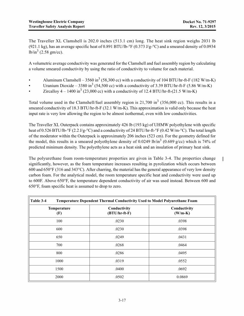
The Traveller XL Clamshell is 202.0 inches (513.1 cm) long. The heat sink region weighs 2031 lb(921.1 kg), has an average specific heat of 0.891 BTU/lb-°F (0.373 J/g-°C) and a smeared density of 0.0934lb/in3 (2.58 gm/cc).
A volumetric average conductivity was generated for the Clamshell and fuel assembly region by calculatinga volume smeared conductivity by using the ratio of conductivity to volume for each material.
• Aluminum Clamshell – 3560 in3 (58,300 cc) with a conductivity of 104 BTU/hr-ft-F (182 W/m-K)• Uranium Dioxide – 3380 in3 (54,500 cc) with a conductivity of 3.39 BTU/hr-ft-F (5.86 W/m-K)• Zircalloy 4 – 1400 in3 (23,000 cc) with a conductivity of 12.4 BTU/hr-ft-(21.5 W/m-K)
Total volume used in the Clamshell/fuel assembly region is 21,700 in3 (356,000 cc). This results in asmeared conductivity of 18.3 BTU/hr-ft-F (32.1 W/m-K). This approximation is valid only because the heatinput rate is very low allowing the region to be almost isothermal, even with low conductivities.
The Traveller XL Outerpack contains approximately 426 lb (193 kg) of UHMW polyethylene with specificheat of 0.526 BTU/lb-°F (2.2 J/g-°C) and a conductivity of 24 BTU/hr-ft-°F (0.42 W/m-°C). The total lengthof the moderator within the Outerpack is approximately 206 inches (523 cm). For the geometry defined forthe model, this results in a smeared polyethylene density of 0.0249 lb/in3 (0.689 g/cc) which is 74% ofpredicted minimum density. The polyethylene acts as a heat sink and an insulation of primary heat sink.
The polyurethane foam room-temperature properties are given in Table 3-4. The properties changesignificantly, however, as the foam temperature increases resulting in pyrolization which occurs between600 and 650°F (316 and 343°C). After charring, the material has the general appearance of very low densitycarbon foam. For the analytical model, the room temperature specific heat and conductivity were used upto 600F. Above 650°F, the temperature dependent conductivity of air was used instead. Between 600 and650°F, foam specific heat is assumed to drop to zero.
Table 3-4 Temperature Dependent Thermal Conductivity Used to Model Polyurethane Foam
Temperature(F)
Conductivity(BTU/hr-ft-F)
Conductivity(W/m-K)
100 .0230 .0398
600 .0230 .0398
650 .0249 .0431
700 .0268 .0464
800 .0286 .0495
1000 .0319 .0552
1500 .0400 .0692
2000 .0502 0.0869
3-17
Westinghouse Electric CompanyTraveller Safety Analysis Report Rev. 1, 11/2004
Docket No. 71-9297
The surface emissivity of the foam was set at 0.8. The first analysis performed modeled a 30 minute firewith flame temperature of 800°C. This analysis, Figure 3-1, showed significant temperature variationthrough the thickness of the polyurethane foam. Peak temperatures on the inside surface of the foam reached100°C approximately 80 minutes after the beginning of the fire (50 minutes after the fire was put out).
Because the planned fire test facility burns at a higher temperature, the same analysis was performedassuming a 1000°C fire temperature. As shown in Figure 3-3, peak temperature within the polyethylene (atthe interface between the polyurethane foam and the polyethylene) was calculated to reach 106°C. This isbelow the 125 – 138°C melt temperature of the polyethylene and well below the temperature that the meltedpolyethylene viscosity is low enough to flow easily.
The thermal analysis performed demonstrated several important features/characteristics of the design.Because of the urethane foam insulating the Outerpack, exterior skin temperatures quickly rise to nearequilibrium with the fire outside the package. The clamshell and fuel assembly temperature, rise very slowlydue to the insulation and the specific heat of the aluminum clamshell, polyethylene moderator, and the fuelassembly. The primary mechanisms that can result in significantly higher internal temperatures is hot gasinfiltration during the fire and internal combustion during and after the fire test. We do not believe that thesemechanisms can be accurately predicted by analysis. As a result, the Traveller team chose to demonstratethe package using pool fire tests, culminating with a full-scale fire test.
The seam burn tests with continuous hinge sections demonstrated approximately 60°C temperature riseduring and after the test which was in close agreement with the 50°C temperature rise predicted by theanalysis. The CTU burn test demonstrated internal temperatures between 116° and 177°C. This is 112° to173°C higher than the air temperature that morning. These values are only 66° to 127°C higher than theequilibrium package temperatures maintained by heaters before the fire. As noted above, the external skintemperature at the middle of the package was significantly higher at the middle. Secondly, the amount ofhot gas entering the package at different locations along the length clearly affects the local internaltemperatures. Greater quantities of hot gas probably entered that package at that location.
Because of the fundamental limitations of the analysis (e.g., inability to predict precise geometry changesduring the fire) the analysis model was never refined and exact agreement was never anticipated with testresults. The analysis does illustrate the fundamental mechanisms involved and the general characteristics ofthe package response, assuming no significant gas infiltration or geometry changes.
3-18

Westinghouse Electric CompanyTraveller Safety Analysis Report Rev. 9, 11/2010
Docket No. 71-9297
3.6.3 Traveller Seam Burn Tests
This test examined two methods of protecting the polyethylene to prevent combustion and/or significantmelting. One was the use of continuous hinges to seal the gap at the seam and the second was to cover themoderator with stainless steel sheet to prevent combustion. A third test section was also created to act as thetest control. This section did not have any additional protection for the moderator.
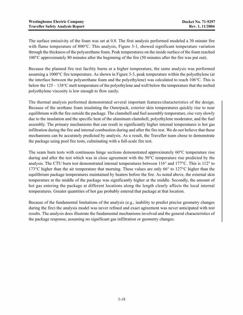
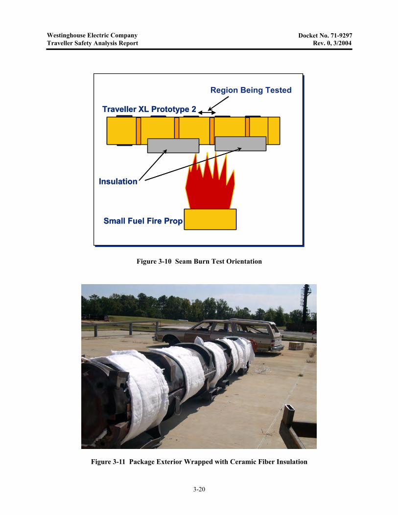
The test was performed as series of three burns, heating the reference or control section, the section withadditional hinge to model a package with continuous hinges, and the section with stainless covering overthe moderator respectively. The first burn lasted 30 minutes. The two subsequent burns lasting for35 minutes. A small pool fire (approximately 30 x 80 inches) was be created under the region of the packageto be tested, Figure 3-10. Each region was approximately 57 cm (22.4 inches) across separated from theadjacent test region by 61 cm (24 inches) of refractory fiber felt insulation. This insulation was stuffedbetween the Clamshell and the moderator to prevent air flow from the section being tested to other testregions within the prototype package. The test regions were selected based having intact moderator left fromprevious tests. The test section with stainless steel cover over the moderator was selected based on theminimum distortion of the inner Outerpack shell and moderator blocks. The outside of the package wasinsulated on the bottom and sides using at least 2.5 cm (one inch) of refractory fiber felt insulation. Thisinsulation will extend at least 1.2 m (48 inches) from each end of the test region, Figure 3-11.
Six thermocouples were attached in each test section. Two were screwed to the moderator bottom edgenearest the seam, one was screwed to the moderator/Outerpack where the two moderator blocks meet, onewas screwed to the moderator block near the top seam, one was screwed to the Clamshell J-clip, and onewas run through the bottom seam to hang approximately four inches below the package in the flames.Thermocouple connections and Teflon coated wires were routed out of the package at each end.
3-19
Westinghouse Electric CompanyTraveller Safety Analysis Report Rev. 0, 3/2004
Docket No. 71-9297
Figure 3-10 Seam Burn Test Orientation
Figure 3-11 Package Exterior Wrapped with Ceramic Fiber Insulation
Region Being Tested
Traveller XL Prototype 2
Small Fuel Fire Prop
Insulation
Region Being Tested
Traveller XL Prototype 2
Small Fuel Fire Prop
Insulation
Traveller XL Prototype 2
Small Fuel Fire Prop
Insulation
3-20
Westinghouse Electric CompanyTraveller Safety Analysis Report Rev. 10, 9/2013
Docket No. 71-9297
3.6.3.1 Test Results
The first test burn was on the unprotected, control section of the package on October 3. Due to strong winds,flames did not stay on the test section. As a result, temperatures remained low and ultimately thethermocouple wires were burnt before the test was completed. Afterward, the weir was modified to extendthe height up to the bottom of the package to confine the flames to the test region.
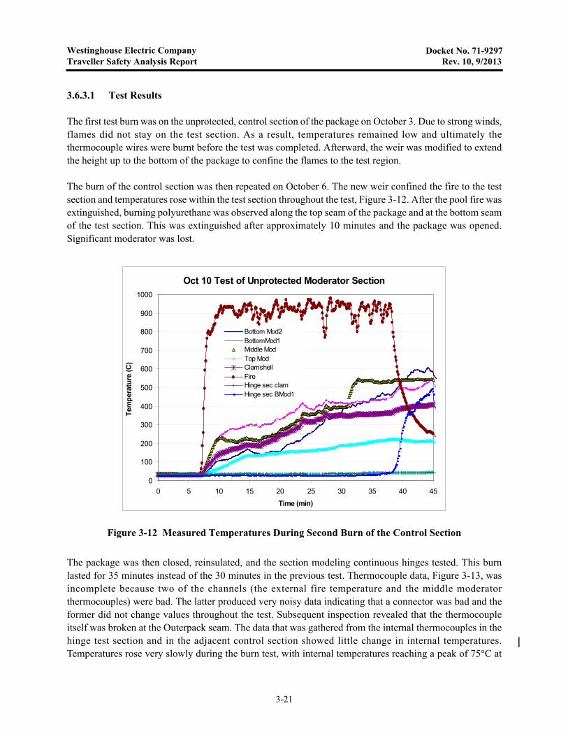
The burn of the control section was then repeated on October 6. The new weir confined the fire to the testsection and temperatures rose within the test section throughout the test, Figure 3-12. After the pool fire wasextinguished, burning polyurethane was observed along the top seam of the package and at the bottom seamof the test section. This was extinguished after approximately 10 minutes and the package was opened.Significant moderator was lost.
The package was then closed, reinsulated, and the section modeling continuous hinges tested. This burnlasted for 35 minutes instead of the 30 minutes in the previous test. Thermocouple data, Figure 3-13, wasincomplete because two of the channels (the external fire temperature and the middle moderatorthermocouples) were bad. The latter produced very noisy data indicating that a connector was bad and theformer did not change values throughout the test. Subsequent inspection revealed that the thermocoupleitself was broken at the Outerpack seam. The data that was gathered from the internal thermocouples in thehinge test section and in the adjacent control section showed little change in internal temperatures.Temperatures rose very slowly during the burn test, with internal temperatures reaching a peak of 75°C at
Figure 3-12 Measured Temperatures During Second Burn of the Control Section
Oct 10 Test of Unprotected Moderator Section
0
100
200
300
400
500
600
700
800
900
1000
0 5 10 15 20 25 30 35 40 45Time (min)
Tem
per
atu
re (C
)
Bottom Mod2BottomMod1Middle ModTop ModClamshellFireHinge sec clamHinge sec BMod1
3-21

Westinghouse Electric CompanyTraveller Safety Analysis Report Rev. 0, 3/2004
Docket No. 71-9297
the end of the test. After this data was collected and saved, additional temperature data was collected duringthe next 30 minutes after the burn, Figure 3-14. Temperatures slowly increased to approximately 100°C.This is consistent with thermal analysis that shows that heat transfer by conduction through the Outerpackpolyurethane foam will continue to add heat to the interior for over an hour after the beginning of the burn,see section 3.1.
3-22

Westinghouse Electric CompanyTraveller Safety Analysis Report Rev. 0, 3/2004
Docket No. 71-9297
Figure 3-13 Interior Temperature Measurements During Test of Continuous Hinge Section
Figure 3-14 Interior Temperature Measures After Test of Continuous Hinge Section
Interior Temperature In Continuous Hinge Section
20
30
40
50
60
70
80
90
100
0 5 10 15 20 25 30 35 40 45 50
Time (min)
Tem
per
atu
re (
C)
Bottom Mod1Bottom Mod2ClamshellTop ModeratorUnprotected Middle ModUnprotected Clam
Fire started
Fire Stopped
Continuous Hinge Interior Cooldown
30
40
50
60
70
80
90
100
50 55 60 65 70 75
Time (min)
Te
mp
era
ture
(C
)
Hinge BMod1Hinge B Mod2Hinge ClamHinge Top ModBare Md ModBare Clam
3-23
Westinghouse Electric CompanyTraveller Safety Analysis Report Rev. 0, 3/2004
Docket No. 71-9297
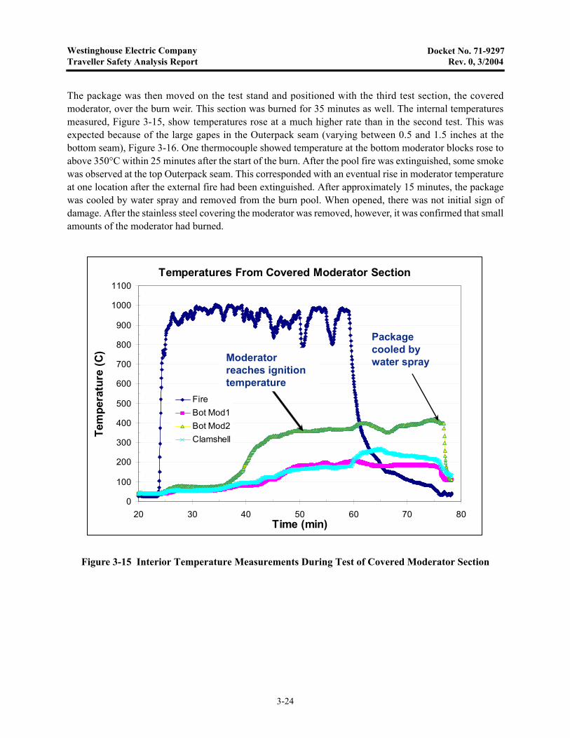
The package was then moved on the test stand and positioned with the third test section, the coveredmoderator, over the burn weir. This section was burned for 35 minutes as well. The internal temperaturesmeasured, Figure 3-15, show temperatures rose at a much higher rate than in the second test. This wasexpected because of the large gapes in the Outerpack seam (varying between 0.5 and 1.5 inches at thebottom seam), Figure 3-16. One thermocouple showed temperature at the bottom moderator blocks rose toabove 350°C within 25 minutes after the start of the burn. After the pool fire was extinguished, some smokewas observed at the top Outerpack seam. This corresponded with an eventual rise in moderator temperatureat one location after the external fire had been extinguished. After approximately 15 minutes, the packagewas cooled by water spray and removed from the burn pool. When opened, there was not initial sign ofdamage. After the stainless steel covering the moderator was removed, however, it was confirmed that smallamounts of the moderator had burned.
Figure 3-15 Interior Temperature Measurements During Test of Covered Moderator Section
Temperatures From Covered Moderator Section
0
100
200
300
400
500
600
700
800
900
1000
1100
20 30 40 50 60 70 80Time (min)
Tem
per
atu
re (
C)
FireBot Mod1Bot Mod2Clamshell
Moderator reaches ignition temperature
Package cooled by water spray
Temperatures From Covered Moderator Section
0
100
200
300
400
500
600
700
800
900
1000
1100
20 30 40 50 60 70 80Time (min)
Tem
per
atu
re (
C)
FireBot Mod1Bot Mod2Clamshell
Moderator reaches ignition temperature
Package cooled by water spray
3-24

Westinghouse Electric CompanyTraveller Safety Analysis Report Rev. 9, 11/2010
Docket No. 71-9297
3.6.3.2 Conclusions
Tests showed that, where the Outerpack seam was covered by a hinge, that hot gas ingestion was virtuallyeliminated. Peak internal temperatures were approximately 100°C. With gaps in the Outerpack seams, peakinternal temperatures exceeded the 350°C ignition temperature of polyethylene. Covering the moderatorwith stainless did appear to reduce heatup rate, even with larger seam gaps, but moderator combustion tookplace anyway. The tests showed that the best approach to prevent moderator combustion is to incorporatecontinuous hinge sections to prevent hot gas ingestion during the burn test.
Figure 3-16 Gaps in Outerpack Bottom Seam at Covered Moderator Test Section
3-25
Westinghouse Electric CompanyTraveller Safety Analysis Report Rev. 10, 9/2013
Docket No. 71-9297
3.6.4 Traveller Impact Limiter Burn Tests
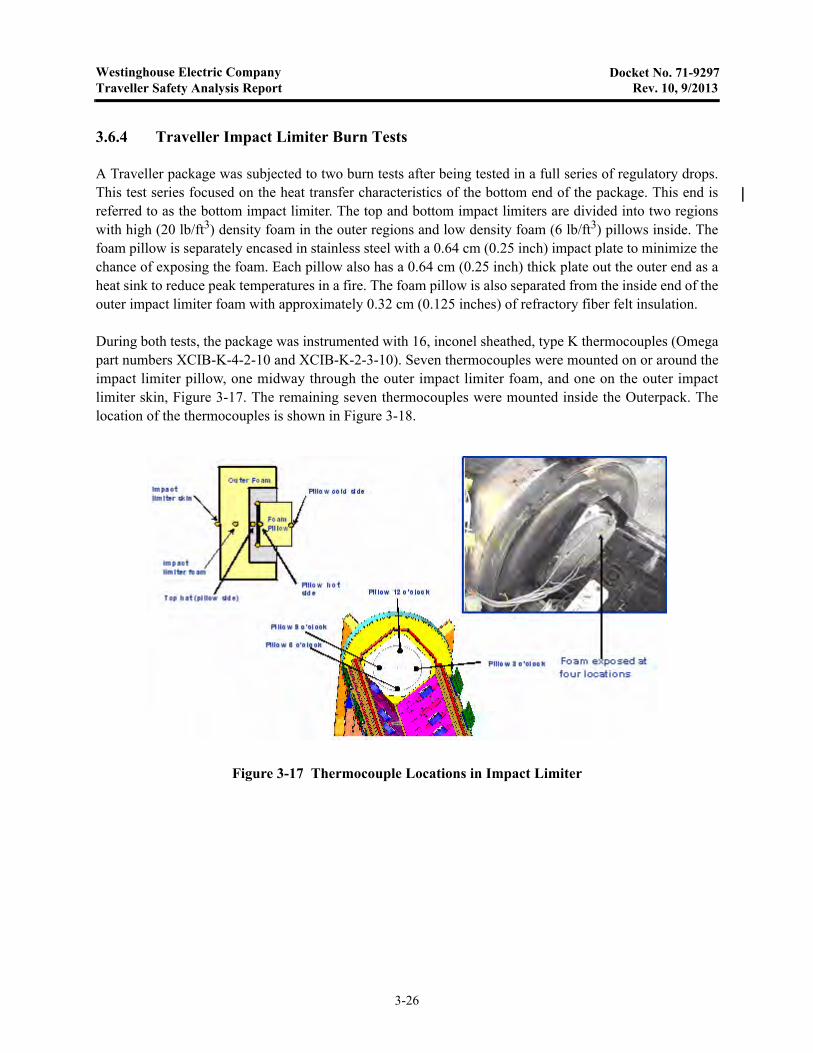
A Traveller package was subjected to two burn tests after being tested in a full series of regulatory drops.This test series focused on the heat transfer characteristics of the bottom end of the package. This end isreferred to as the bottom impact limiter. The top and bottom impact limiters are divided into two regionswith high (20 lb/ft3) density foam in the outer regions and low density foam (6 lb/ft3) pillows inside. Thefoam pillow is separately encased in stainless steel with a 0.64 cm (0.25 inch) impact plate to minimize thechance of exposing the foam. Each pillow also has a 0.64 cm (0.25 inch) thick plate out the outer end as aheat sink to reduce peak temperatures in a fire. The foam pillow is also separated from the inside end of theouter impact limiter foam with approximately 0.32 cm (0.125 inches) of refractory fiber felt insulation.
During both tests, the package was instrumented with 16, inconel sheathed, type K thermocouples (Omegapart numbers XCIB-K-4-2-10 and XCIB-K-2-3-10). Seven thermocouples were mounted on or around theimpact limiter pillow, one midway through the outer impact limiter foam, and one on the outer impactlimiter skin, Figure 3-17. The remaining seven thermocouples were mounted inside the Outerpack. Thelocation of the thermocouples is shown in Figure 3-18.
Figure 3-17 Thermocouple Locations in Impact Limiter
3-26

Westinghouse Electric CompanyTraveller Safety Analysis Report Rev. 0, 3/2004
Docket No. 71-9297
The thermocouples were connected to thermocouple wire extensions using standard Type K plugsconnecting the thermocouples to 20 gage type K extension wire. The 16 thermocouple cables wereconnected to two data acquisition systems. One system used an Omega OM-CP-OCTTEMP 8-channel datalogger. This unit was set in operation before the test using a laptop computer and stored data from eachchannel at a rate of 12 samples per minute. After the test was completed, the data was download to the samelaptop computer. The second system used an 8-channel Omega INET-100 external A/D box connected to anINET-230 PC-Card controller with a INET 311-2 power supply. This recorded data directly into the laptopcomputer allowing these channels to be monitored during the test.
Additional data was taken on external temperatures using two OMEGA OS523 handheld opticalthermometers during the December 15 test. These units were used to measure flame temperatures andoutside package skin temperature after the pool fire was extinguished.
A previously drop tested unit was modified to incorporate these changes in the bottom impact limiter andwas subjected to two burns, one on December 15, and the second on December 16. Both burns engulfed thebottom impact limiter and approximately 3 feet of the package above the bottom impact limiter.Thermocouples were mounted at 16 locations inside and outside the package. Data from eight of thethermocouples were recorded by a laptop PC based Instrunet system that allowed data to be monitored inreal time. The other eight channels were recorded using a battery powered Omega data logger.
Figure 3-18 Thermocouple Locations in Outerpack Interior
3-27
Westinghouse Electric CompanyTraveller Safety Analysis Report Rev. 9, 11/2010
Docket No. 71-9297
3.6.4.1 First Impact Limiter Burn (December 15)
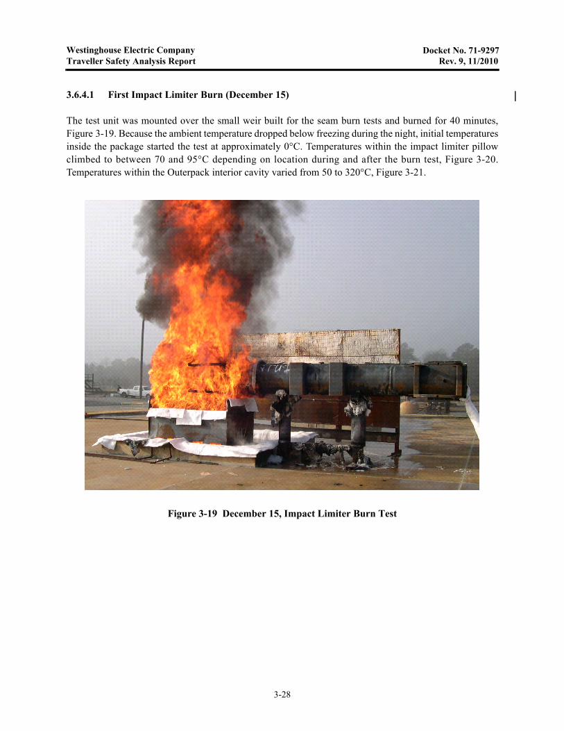
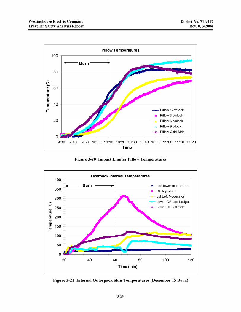
The test unit was mounted over the small weir built for the seam burn tests and burned for 40 minutes,Figure 3-19. Because the ambient temperature dropped below freezing during the night, initial temperaturesinside the package started the test at approximately 0°C. Temperatures within the impact limiter pillowclimbed to between 70 and 95°C depending on location during and after the burn test, Figure 3-20.Temperatures within the Outerpack interior cavity varied from 50 to 320°C, Figure 3-21.
Figure 3-19 December 15, Impact Limiter Burn Test
3-28
Westinghouse Electric CompanyTraveller Safety Analysis Report Rev, 0, 3/2004
Docket No. 71-9297
Figure 3-20 Impact Limiter Pillow Temperatures
Figure 3-21 Internal Outerpack Skin Temperatures (December 15 Burn)
Pillow Temperatures
0
20
40
60
80
100
9:30 9:40 9:50 10:00 10:10 10:20 10:30 10:40 10:50 11:00 11:10 11:20Time
Tem
pe
ratu
re (
C)
Pillow 12o'clockPillow 3 o'clockPillow 6 o'clockPillow 9 o'lockPillow Cold Side
Burn
Overpack Internal Temperatures
0
50
100
150
200
250
300
350
400
20 40 60 80 100 120
Time (min)
Te
mp
era
ture
(C)
Left lower moderatorOP top seamLid Left ModeratorLower OP Left LedgeLower OP left Side
Burn
3-29

Westinghouse Electric CompanyTraveller Safety Analysis Report Rev, 0, 3/2004
Docket No. 71-9297
During this test, external temperatures were measured with two optical thermometers. Readings were takenevery five minutes, Figure 3-22. After the test was completed, the Outerpack was opened. Other than a thinlayer of soot lining the inside surfaces, there was no noticeable change in the Outerpack or Clamshell,Figure 3-23.
Figure 3-22 Flame Temperatures Measured by Optical Pyrometers
Figure 3-23 Outerpack Internals after December 15 Burn Test
Optical Thermometer Readings
0
200
400
600
800
1000
1200
1400
0 10 20 30 40Time (min)
Te
mp
era
ture
(C
)
Unit 1 (C )Unit 2 (C )
3-30
Westinghouse Electric CompanyTraveller Safety Analysis Report Rev. 9, 11/2010
Docket No. 71-9297
3.6.4.2 Second Impact Limiter Burn (December 16)
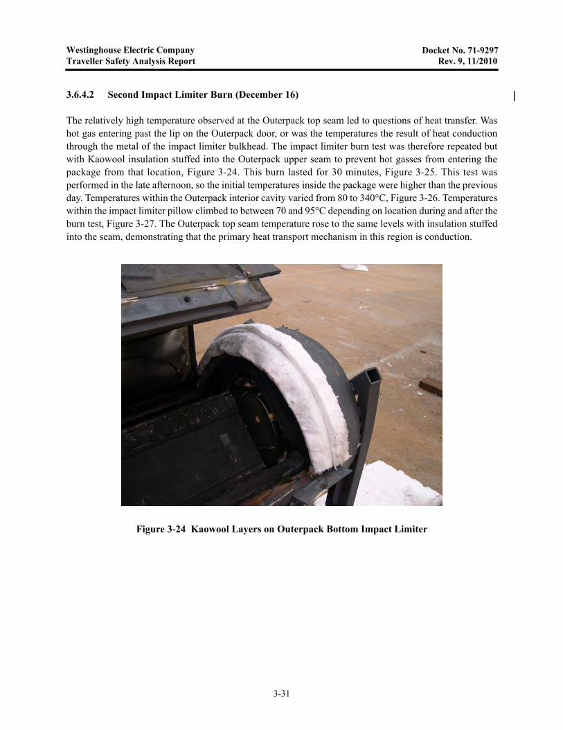
The relatively high temperature observed at the Outerpack top seam led to questions of heat transfer. Washot gas entering past the lip on the Outerpack door, or was the temperatures the result of heat conductionthrough the metal of the impact limiter bulkhead. The impact limiter burn test was therefore repeated butwith Kaowool insulation stuffed into the Outerpack upper seam to prevent hot gasses from entering thepackage from that location, Figure 3-24. This burn lasted for 30 minutes, Figure 3-25. This test wasperformed in the late afternoon, so the initial temperatures inside the package were higher than the previousday. Temperatures within the Outerpack interior cavity varied from 80 to 340°C, Figure 3-26. Temperatureswithin the impact limiter pillow climbed to between 70 and 95°C depending on location during and after theburn test, Figure 3-27. The Outerpack top seam temperature rose to the same levels with insulation stuffedinto the seam, demonstrating that the primary heat transport mechanism in this region is conduction.
Figure 3-24 Kaowool Layers on Outerpack Bottom Impact Limiter
3-31

Westinghouse Electric CompanyTraveller Safety Analysis Report Rev. 0, 3/2004
Docket No. 71-9297
Figure 3-25 December 16 Impact Limiter Burn
Figure 3-26 Internal Outerpack Skin Temperatures (December 16 Burn)
Overpack Interior Temperatures
0
50
100
150
200
250
300
350
10 15 20 25 30 35 40 45 50 55 60 65 70 75 80 85Time (min)
Tem
per
atu
re (
C)
OP top seam
Lower OP rt side
Lid Mod Left
Lower OP left seam
Lid Mod Rt
Left Lower Mod
Lower OP left ledge
Burn
3-32
Westinghouse Electric CompanyTraveller Safety Analysis Report Rev. 9, 11/2010
Docket No. 71-9297
3.6.4.3 Test Conclusions
The purpose of the December 16 test was to repeat the previous day’s test ensuring that hot gases did notflow around the Outerpack lid bottom lip. The heat up rate of the Outerpack top seam was slightly higherduring the second burn than the first. Three factors may explain the higher temperatures during the secondtest.
• Foam in the impact limiter was charred during the first test resulting in higher heat transfer duringthe second test.
• The kaowool used to fill the bottom seam prevented the lid from closing as tightly as in the firsttest. This may have allow small amounts of combustion gas from the pool to enter the package
• During the first 5-6 minutes of the burn, fuel was sprayed directly on the outer skin of the package.
The test demonstrated that the revised impact limiter design will not overheat during a regulatory burn test.Even if the initial temperature is raised by 50°C, final temperature of the impact limiter pillow is anticipateto be less than 150°C. The test also demonstrated that very little gas is entering the Outerpack through theside or top seams. The interior skin is heating up however, due to conduction through metal parts of theOuterpack and through the polyurethane foam. The impact limiter tests results are conservative because the
Figure 3-27 Impact Limiter Pillow Temperatures (December 16 Burn)
Pillow Temperatures
0
20
40
60
80
100
120
140
20 30 40 50 60 70 80 90 100Time (min)
Te
mp
era
ture
(C
)
Pillow 6 o'clockPillow 9 o'clockPillow 12 o'clockPillow cold sideTop hat
Burn
3-33

Westinghouse Electric CompanyTraveller Safety Analysis Report Rev. 0, 3/2004
Docket No. 71-9297
foam in the cylindrical section of the package was not replaced and, therefore, did not provide the insulationthat a unburnt package would have.
3-34

Westinghouse Electric CompanyTraveller Safety Analysis Report Rev. 10, 9/2013
Docket No. 71-9297
3.6.5 Traveller Certification Test Unit Burn Test
A Traveller XL package was fabricated by Columbiana High Tech to serve as the certification test article.This unit was subjected to a regulatory drop test performed February 5, 2004 in Columbiana, Ohio. Thispackage was transported to the South Carolina Fire Academy in Columbia, South Carolina on February 6.The package was installed in the burn pool and burned February 10, 2004, Figure 3-28. Although theOuterpack had suffered minor damage that allowed some urethane decomposition products to escape intothe package interior, the fuel assembly, Clamshell, and polyethylene moderator were essentiallyundamaged. (Please see section 2.12.4.2.3 in the Safety Analysis Report (pp 3-183 through 3-192) fordescription of the CTU drop tests and the resulting damage.)
The test was performed with the following objectives:
• Test Traveller package in manner that meets or exceeds regulatory requirements of TS-R-1 and10CFR71.
• Demonstrate that the fuel assembly survives intact, without potential release of radioactivity.
• Demonstrate that the polyethylene moderator survives essentially intact retaining at least 90% ofthe hydrogen within the polyethylene.
• Demonstrate that the fuel assembly survives without cladding rupture caused by excessivetemperatures inside the Clamshell
Figure 3-27A shows the orientation of the Certification Test Unit (CTU) for the thermal test. The bottom ofthe package was positioned approximately 1 meter from the top of the fire pool surface. The distance of theouter facility walls beyond the edge of the package were 67" at the ends and 71.5" at the sides.
Figure 3-27A Orientation of CTU for Thermal Test
3-35
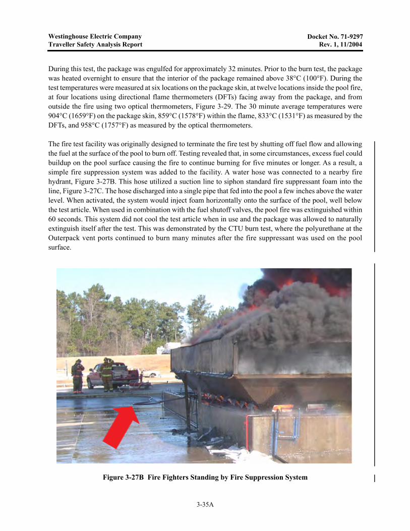
Westinghouse Electric CompanyTraveller Safety Analysis Report Rev. 1, 11/2004
Docket No. 71-9297
During this test, the package was engulfed for approximately 32 minutes. Prior to the burn test, the packagewas heated overnight to ensure that the interior of the package remained above 38°C (100°F). During thetest temperatures were measured at six locations on the package skin, at twelve locations inside the pool fire,at four locations using directional flame thermometers (DFTs) facing away from the package, and fromoutside the fire using two optical thermometers, Figure 3-29. The 30 minute average temperatures were904°C (1659°F) on the package skin, 859°C (1578°F) within the flame, 833°C (1531°F) as measured by theDFTs, and 958°C (1757°F) as measured by the optical thermometers.
The fire test facility was originally designed to terminate the fire test by shutting off fuel flow and allowingthe fuel at the surface of the pool to burn off. Testing revealed that, in some circumstances, excess fuel couldbuildup on the pool surface causing the fire to continue burning for five minutes or longer. As a result, asimple fire suppression system was added to the facility. A water hose was connected to a nearby firehydrant, Figure 3-27B. This hose utilized a suction line to siphon standard fire suppressant foam into theline, Figure 3-27C. The hose discharged into a single pipe that fed into the pool a few inches above the waterlevel. When activated, the system would inject foam horizontally onto the surface of the pool, well belowthe test article. When used in combination with the fuel shutoff valves, the pool fire was extinguished within60 seconds. This system did not cool the test article when in use and the package was allowed to naturallyextinguish itself after the test. This was demonstrated by the CTU burn test, where the polyurethane at theOuterpack vent ports continued to burn many minutes after the fire suppressant was used on the poolsurface.
Figure 3-27B Fire Fighters Standing by Fire Suppression System
3-35A
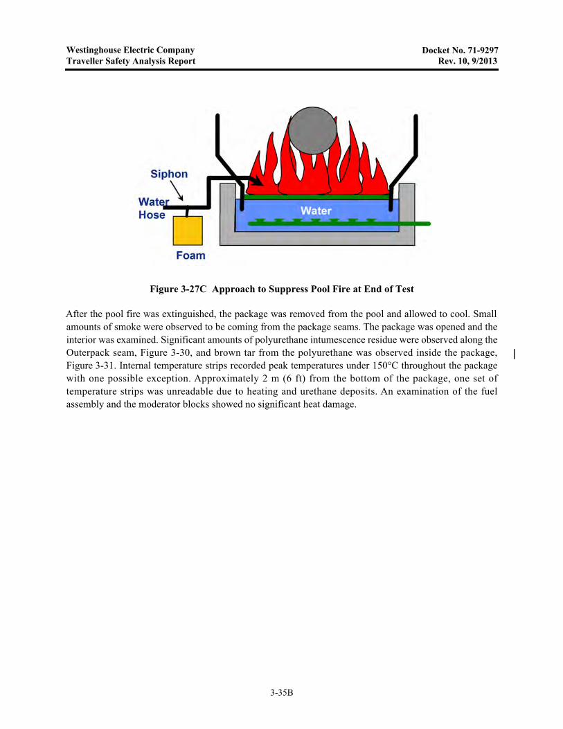
Westinghouse Electric CompanyTraveller Safety Analysis Report Rev. 10, 9/2013
Docket No. 71-9297
After the pool fire was extinguished, the package was removed from the pool and allowed to cool. Smallamounts of smoke were observed to be coming from the package seams. The package was opened and theinterior was examined. Significant amounts of polyurethane intumescence residue were observed along theOuterpack seam, Figure 3-30, and brown tar from the polyurethane was observed inside the package,Figure 3-31. Internal temperature strips recorded peak temperatures under 150°C throughout the packagewith one possible exception. Approximately 2 m (6 ft) from the bottom of the package, one set oftemperature strips was unreadable due to heating and urethane deposits. An examination of the fuelassembly and the moderator blocks showed no significant heat damage.
Figure 3-27C Approach to Suppress Pool Fire at End of Test
3-35B

Westinghouse Electric CompanyTraveller Safety Analysis Report Rev. 0, 3/2004
Docket No. 71-9297
Figure 3-28 Traveller CTU Burn Test
Figure 3-29 Thermocouple Locations on CTU Burn Test
TCs attached 8"from end of package
NW upperand lowerTCs
Directional FlameThermometer(6)
3-36
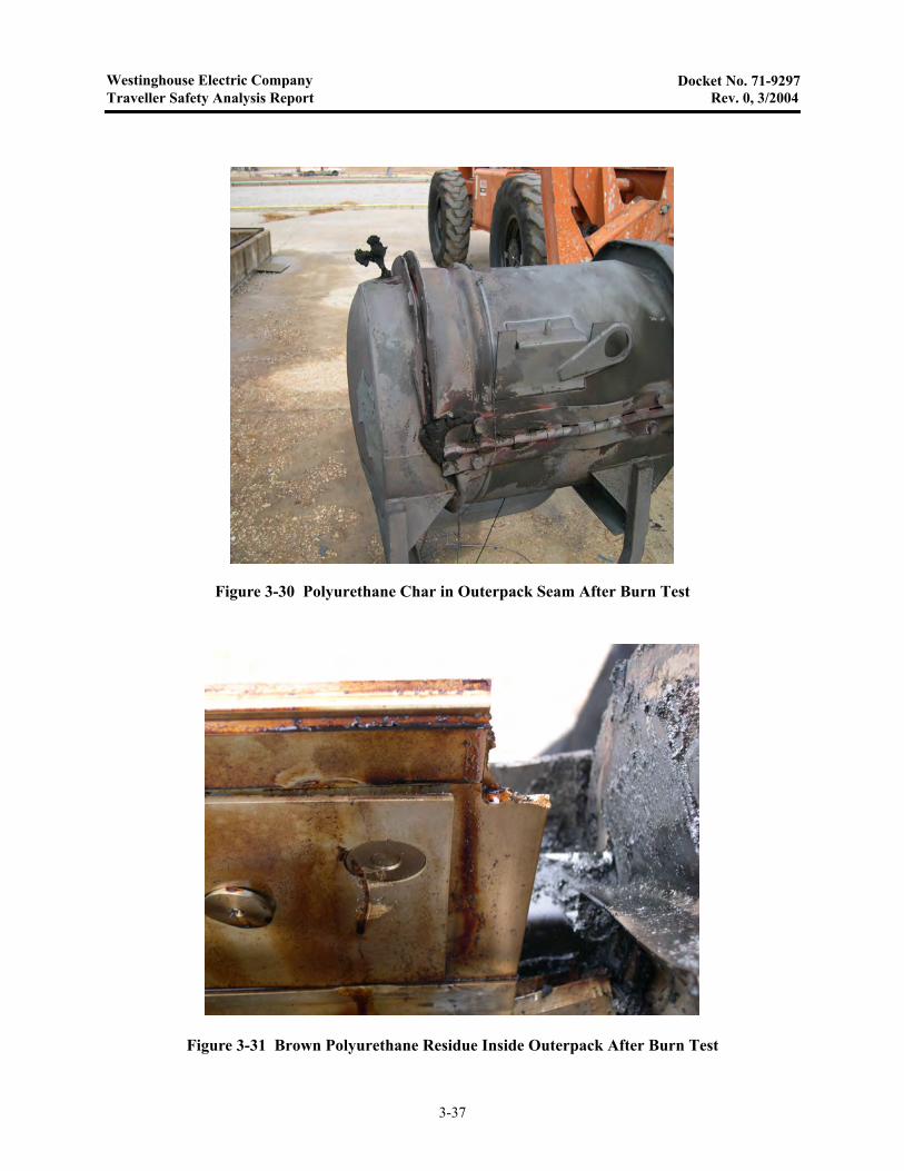
Westinghouse Electric CompanyTraveller Safety Analysis Report Rev. 0, 3/2004
Docket No. 71-9297
Figure 3-30 Polyurethane Char in Outerpack Seam After Burn Test
Figure 3-31 Brown Polyurethane Residue Inside Outerpack After Burn Test
3-37
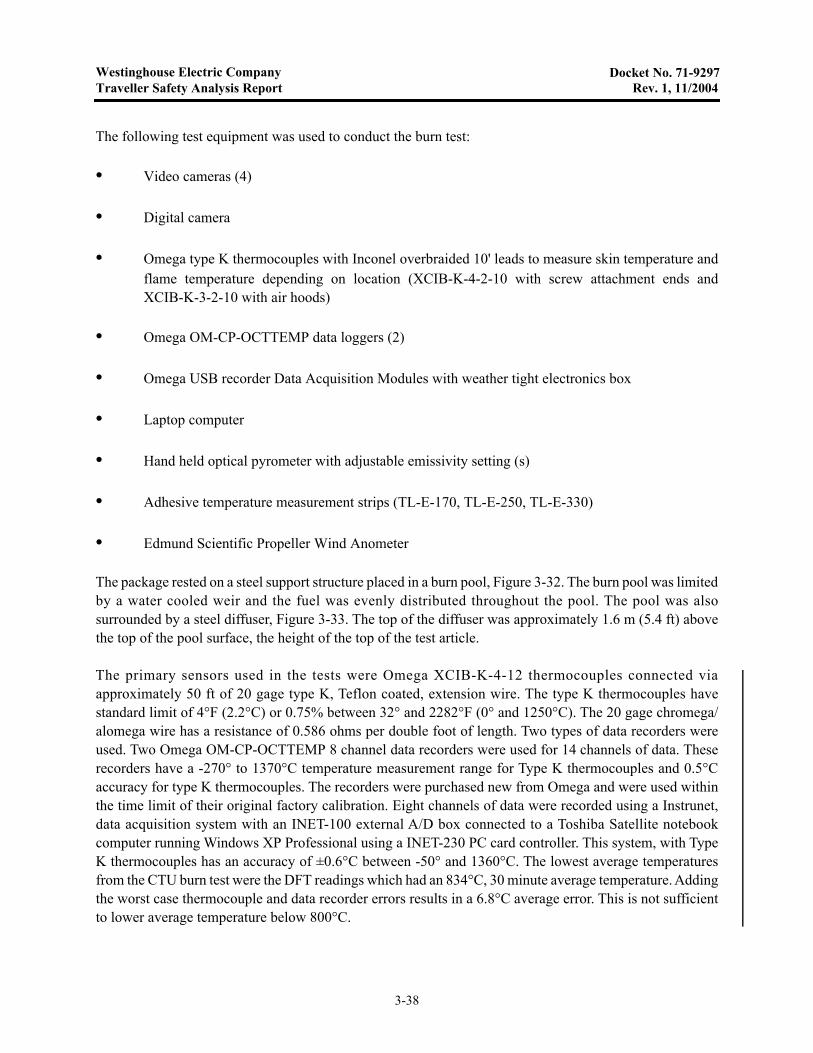
Westinghouse Electric CompanyTraveller Safety Analysis Report Rev. 1, 11/2004
Docket No. 71-9297
The following test equipment was used to conduct the burn test:
• Video cameras (4)
• Digital camera
• Omega type K thermocouples with Inconel overbraided 10' leads to measure skin temperature andflame temperature depending on location (XCIB-K-4-2-10 with screw attachment ends andXCIB-K-3-2-10 with air hoods)
• Omega OM-CP-OCTTEMP data loggers (2)
• Omega USB recorder Data Acquisition Modules with weather tight electronics box
• Laptop computer
• Hand held optical pyrometer with adjustable emissivity setting (s)
• Adhesive temperature measurement strips (TL-E-170, TL-E-250, TL-E-330)
• Edmund Scientific Propeller Wind Anometer
The package rested on a steel support structure placed in a burn pool, Figure 3-32. The burn pool was limitedby a water cooled weir and the fuel was evenly distributed throughout the pool. The pool was alsosurrounded by a steel diffuser, Figure 3-33. The top of the diffuser was approximately 1.6 m (5.4 ft) abovethe top of the pool surface, the height of the top of the test article.
The primary sensors used in the tests were Omega XCIB-K-4-12 thermocouples connected viaapproximately 50 ft of 20 gage type K, Teflon coated, extension wire. The type K thermocouples havestandard limit of 4°F (2.2°C) or 0.75% between 32° and 2282°F (0° and 1250°C). The 20 gage chromega/alomega wire has a resistance of 0.586 ohms per double foot of length. Two types of data recorders wereused. Two Omega OM-CP-OCTTEMP 8 channel data recorders were used for 14 channels of data. Theserecorders have a -270° to 1370°C temperature measurement range for Type K thermocouples and 0.5°Caccuracy for type K thermocouples. The recorders were purchased new from Omega and were used withinthe time limit of their original factory calibration. Eight channels of data were recorded using a Instrunet,data acquisition system with an INET-100 external A/D box connected to a Toshiba Satellite notebookcomputer running Windows XP Professional using a INET-230 PC card controller. This system, with TypeK thermocouples has an accuracy of ±0.6°C between -50° and 1360°C. The lowest average temperaturesfrom the CTU burn test were the DFT readings which had an 834°C, 30 minute average temperature. Addingthe worst case thermocouple and data recorder errors results in a 6.8°C average error. This is not sufficientto lower average temperature below 800°C.
3-38
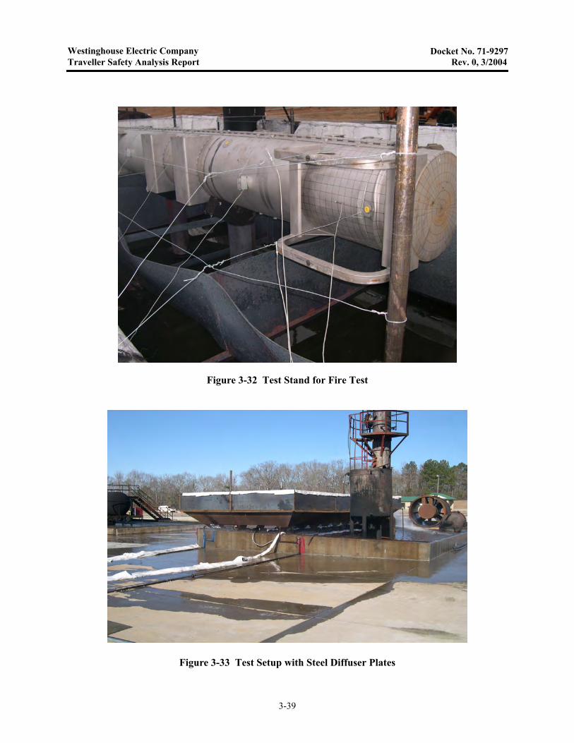
Westinghouse Electric CompanyTraveller Safety Analysis Report Rev. 0, 3/2004
Docket No. 71-9297
Figure 3-32 Test Stand for Fire Test
Figure 3-33 Test Setup with Steel Diffuser Plates
3-39

Westinghouse Electric CompanyTraveller Safety Analysis Report Rev. 10, 9/2013
Docket No. 71-9297
3.6.5.1 Test Procedures and Results
The Certification Test Unit 1 (CTU) was burn tested on February 10, 2004. Because the overnighttemperatures dropped to near freezing, the package was covered with a tarp, Figure 3-34 and heated by two150,000 BTU/hr (44 kWt) kerosene heaters used alternatively. The heaters maintained the air temperatureunder the tent between 40 and 80°C (104 and 176°F) with readings at one location climbing to 115°C(239°F). The heater was turned off shortly after 7:15 AM and the tarp was removed between 7:20 and8:00 AM. Temperatures around the package were measured and recorded on the two data loggers. This datais shown on, Figures 3-35 and 3-36. The ambient temperature shown is air temperature outside of the heatedtent.
This test was performed between 8:32 and 9:06 AM Tuesday morning. Fuel was added to the pool startingat 8:26 AM and continued until 150 gal had been added. The pool was lit at 8:32 and full engulfment wasachieved one minute later. After full engulfment was achieved, fuel flow was adjusted to between 61 and83 l/min (16 and 22 gal/min) depending on the flame coverage within the pool. The fuel flow was securedat 9:04 and the fire suppression system was activated one minute later. The pool fire was extinguished withinapproximately one minute, although burning polyurethane from the package reignited residual fuel at oneend of the pool shortly afterwards. This was extinguished using the fire suppression system.
Figure 3-34 Test Article Under Tent to Maintain Temperature Overnight
3-40
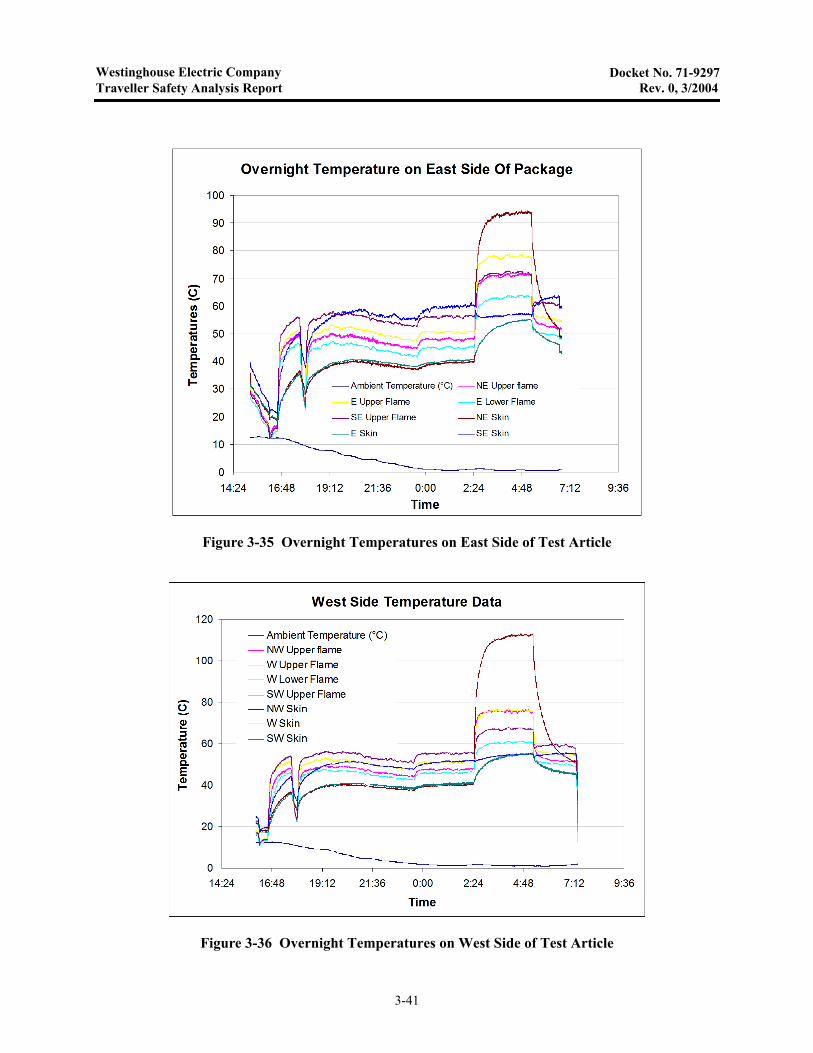
Westinghouse Electric CompanyTraveller Safety Analysis Report Rev. 0, 3/2004
Docket No. 71-9297
Figure 3-35 Overnight Temperatures on East Side of Test Article
Figure 3-36 Overnight Temperatures on West Side of Test Article
3-41
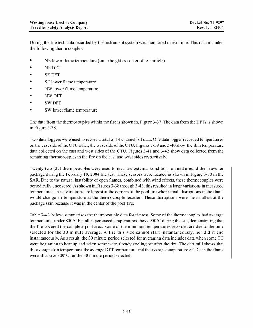
Westinghouse Electric CompanyTraveller Safety Analysis Report Rev. 1, 11/2004
Docket No. 71-9297
During the fire test, data recorded by the instrument system was monitored in real time. This data includedthe following thermocouples:
• NE lower flame temperature (same height as center of test article)• NE DFT• SE DFT• SE lower flame temperature• NW lower flame temperature• NW DFT• SW DFT• SW lower flame temperature
The data from the thermocouples within the fire is shown in, Figure 3-37. The data from the DFTs is shownin Figure 3-38.
Two data loggers were used to record a total of 14 channels of data. One data logger recorded temperatureson the east side of the CTU other, the west side of the CTU. Figures 3-39 and 3-40 show the skin temperaturedata collected on the east and west sides of the CTU. Figures 3-41 and 3-42 show data collected from theremaining thermocouples in the fire on the east and west sides respectively.
Twenty-two (22) thermocouples were used to measure external conditions on and around the Travellerpackage during the February 10, 2004 fire test. These sensors were located as shown in Figure 3-30 in theSAR. Due to the natural instability of open flames, combined with wind effects, these thermocouples wereperiodically uncovered. As shown in Figures 3-38 through 3-43, this resulted in large variations in measuredtemperature. These variations are largest at the corners of the pool fire where small disruptions in the flamewould change air temperature at the thermocouple location. These disruptions were the smallest at thepackage skin because it was in the center of the pool fire.
Table 3-4A below, summarizes the thermocouple data for the test. Some of the thermocouples had averagetemperatures under 800°C but all experienced temperatures above 900°C during the test, demonstrating thatthe fire covered the complete pool area. Some of the minimum temperatures recorded are due to the timeselected for the 30 minute average. A fire this size cannot start instantaneously, nor did it endinstantaneously. As a result, the 30 minute period selected for averaging data includes data when some TCwere beginning to heat up and when some were already cooling off after the fire. The data still shows thatthe average skin temperature, the average DFT temperature and the average temperature of TCs in the flamewere all above 800°C for the 30 minute period selected.
3-42
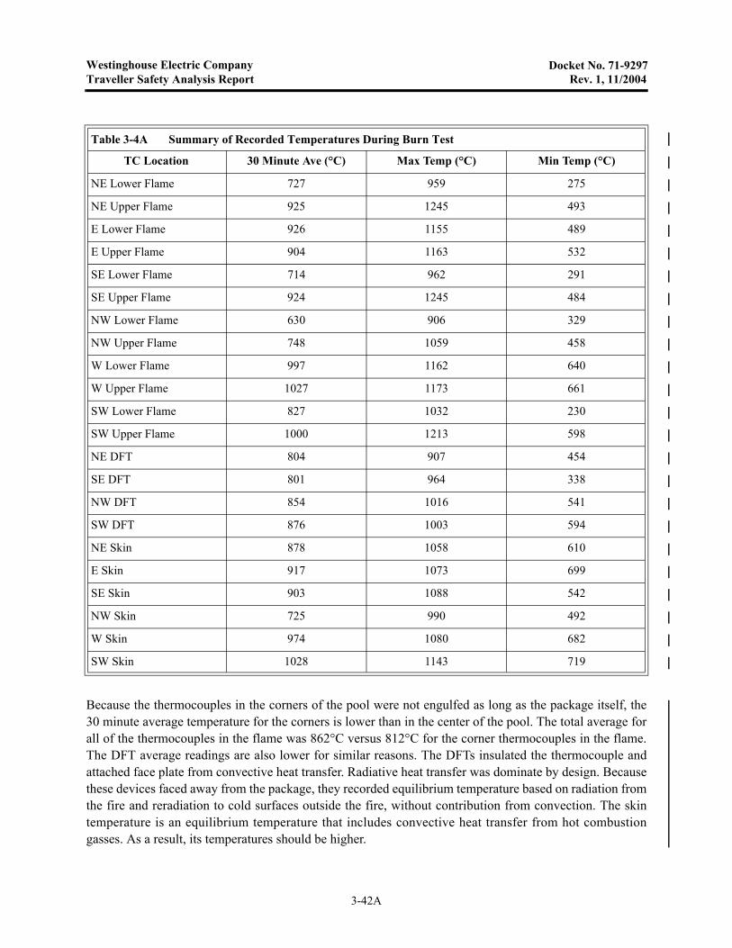
Westinghouse Electric CompanyTraveller Safety Analysis Report Rev. 1, 11/2004
Docket No. 71-9297
Because the thermocouples in the corners of the pool were not engulfed as long as the package itself, the30 minute average temperature for the corners is lower than in the center of the pool. The total average forall of the thermocouples in the flame was 862°C versus 812°C for the corner thermocouples in the flame.The DFT average readings are also lower for similar reasons. The DFTs insulated the thermocouple andattached face plate from convective heat transfer. Radiative heat transfer was dominate by design. Becausethese devices faced away from the package, they recorded equilibrium temperature based on radiation fromthe fire and reradiation to cold surfaces outside the fire, without contribution from convection. The skintemperature is an equilibrium temperature that includes convective heat transfer from hot combustiongasses. As a result, its temperatures should be higher.
Table 3-4A Summary of Recorded Temperatures During Burn Test
TC Location 30 Minute Ave (°C) Max Temp (°C) Min Temp (°C)
NE Lower Flame 727 959 275
NE Upper Flame 925 1245 493
E Lower Flame 926 1155 489
E Upper Flame 904 1163 532
SE Lower Flame 714 962 291
SE Upper Flame 924 1245 484
NW Lower Flame 630 906 329
NW Upper Flame 748 1059 458
W Lower Flame 997 1162 640
W Upper Flame 1027 1173 661
SW Lower Flame 827 1032 230
SW Upper Flame 1000 1213 598
NE DFT 804 907 454
SE DFT 801 964 338
NW DFT 854 1016 541
SW DFT 876 1003 594
NE Skin 878 1058 610
E Skin 917 1073 699
SE Skin 903 1088 542
NW Skin 725 990 492
W Skin 974 1080 682
SW Skin 1028 1143 719
3-42A

Westinghouse Electric CompanyTraveller Safety Analysis Report Rev. 1, 11/2004
Docket No. 71-9297
As described in the discussion of thermal analysis results (section 3.6.1) the long length to diameter ratio ofthe Traveller package minimizes the role of axial heat transfer inside the package. Non-uniform externaltemperatures produce non-uniform internal temperatures during fire tests. This fundamental mechanismallowed useful data to be obtained in the seam burn and impact limiter burn tests described in sections 3.6.2and 3.6.3. This mechanism was demonstrated by the very low clamshell temperatures measured adjacent tothe heated sections in those tests. During the CTU burn test, the average skin temperature at the North end,middle and South end of the package was 801°, 946°, and 915°C respectively. Peak interior temperaturesrecorded by the non-reversible temperatures strips were 116°C at the North end of the package, 177°C atthe middle of the package, and 143°C at the South end of the package. At the center of the package, wherethe average exterior skin temperature was 946°C, the corresponding interior temperatures were acceptablefor all materials in the package.
Figure 3-37 Fire Temperatures Measured at the Corners of the Pool
Monitored Burn Test Temperature Data
0
200
400
600
800
1,000
1,200
-10 0 10 20 30 40 50Time (min)
Tem
per
atu
re (
C)
NE Lower flameSE Lower flameNW Lower flameSW Lower flame
3-42B
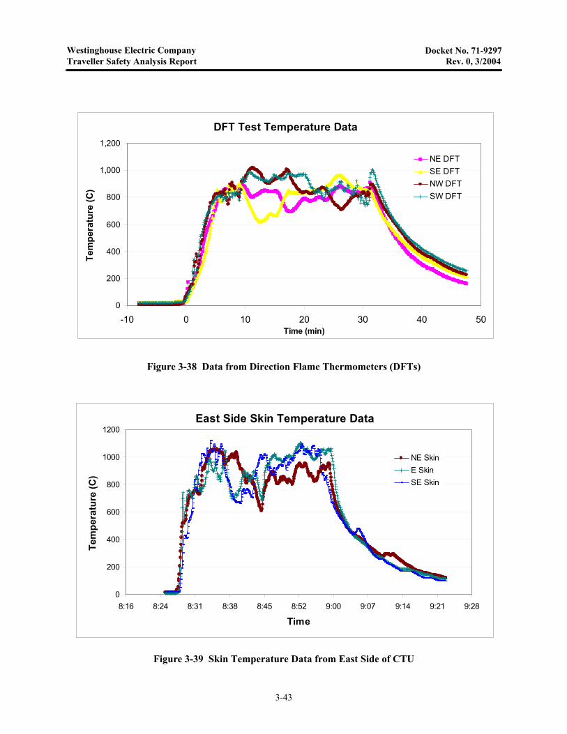
Westinghouse Electric CompanyTraveller Safety Analysis Report Rev. 0, 3/2004
Docket No. 71-9297
Figure 3-38 Data from Direction Flame Thermometers (DFTs)
Figure 3-39 Skin Temperature Data from East Side of CTU
DFT Test Temperature Data
0
200
400
600
800
1,000
1,200
-10 0 10 20 30 40 50Time (min)
Tem
per
atu
re (
C)
NE DFTSE DFTNW DFTSW DFT
East Side Skin Temperature Data
0
200
400
600
800
1000
1200
8:16 8:24 8:31 8:38 8:45 8:52 9:00 9:07 9:14 9:21 9:28
Time
Tem
per
atu
re (
C)
NE SkinE SkinSE Skin
3-43
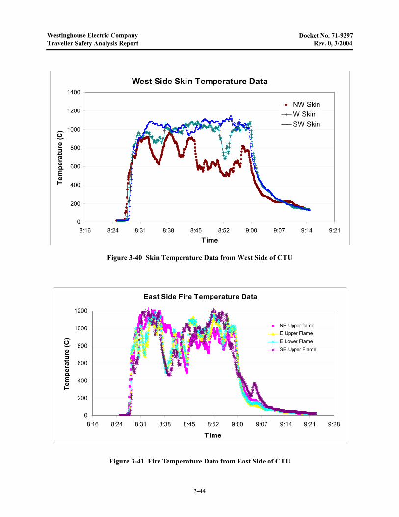
Westinghouse Electric CompanyTraveller Safety Analysis Report Rev. 0, 3/2004
Docket No. 71-9297
Figure 3-40 Skin Temperature Data from West Side of CTU
Figure 3-41 Fire Temperature Data from East Side of CTU
West Side Skin Temperature Data
0
200
400
600
800
1000
1200
1400
8:16 8:24 8:31 8:38 8:45 8:52 9:00 9:07 9:14 9:21
Time
Te
mp
era
ture
(C
)
NW SkinW SkinSW Skin
East Side Fire Temperature Data
0
200
400
600
800
1000
1200
8:16 8:24 8:31 8:38 8:45 8:52 9:00 9:07 9:14 9:21 9:28
Time
Tem
pe
ratu
re (
C)
NE Upper flameE Upper FlameE Lower FlameSE Upper Flame
3-44
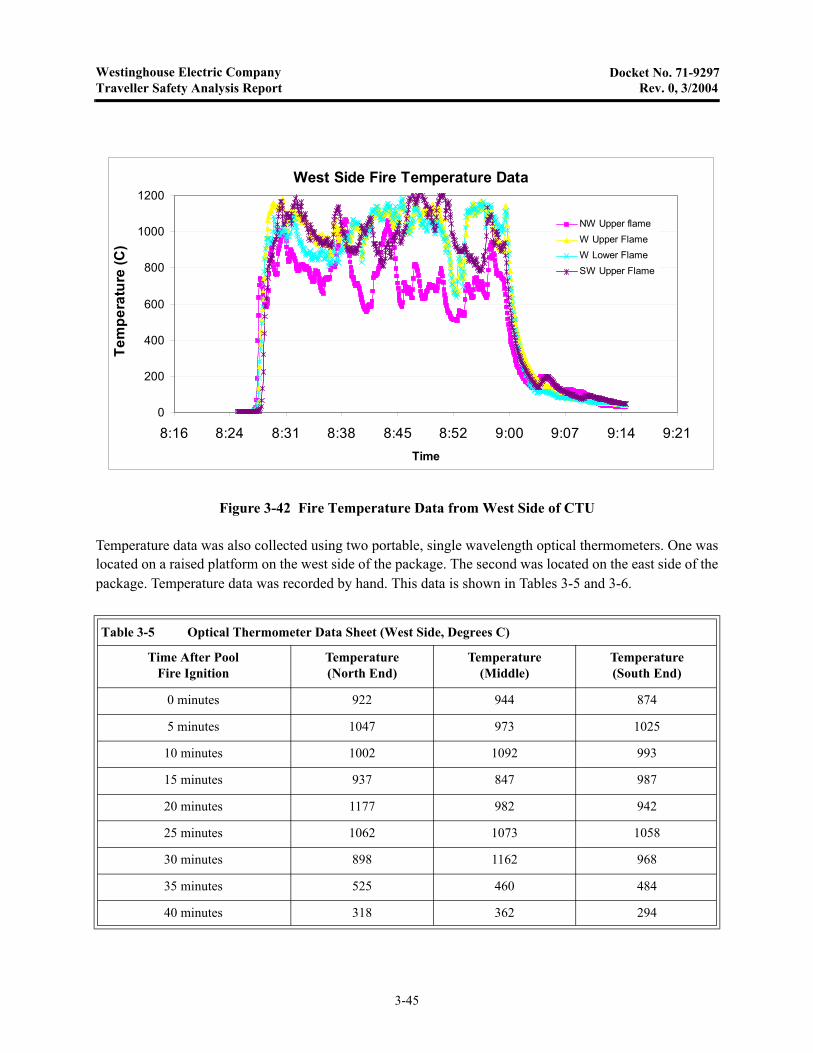
Westinghouse Electric CompanyTraveller Safety Analysis Report Rev. 0, 3/2004
Docket No. 71-9297
Temperature data was also collected using two portable, single wavelength optical thermometers. One waslocated on a raised platform on the west side of the package. The second was located on the east side of thepackage. Temperature data was recorded by hand. This data is shown in Tables 3-5 and 3-6.
Figure 3-42 Fire Temperature Data from West Side of CTU
Table 3-5 Optical Thermometer Data Sheet (West Side, Degrees C)
Time After Pool Fire Ignition
Temperature(North End)
Temperature(Middle)
Temperature(South End)
0 minutes 922 944 874
5 minutes 1047 973 1025
10 minutes 1002 1092 993
15 minutes 937 847 987
20 minutes 1177 982 942
25 minutes 1062 1073 1058
30 minutes 898 1162 968
35 minutes 525 460 484
40 minutes 318 362 294
West Side Fire Temperature Data
0
200
400
600
800
1000
1200
8:16 8:24 8:31 8:38 8:45 8:52 9:00 9:07 9:14 9:21Time
Te
mp
era
ture
(C
)
NW Upper flameW Upper FlameW Lower FlameSW Upper Flame
3-45
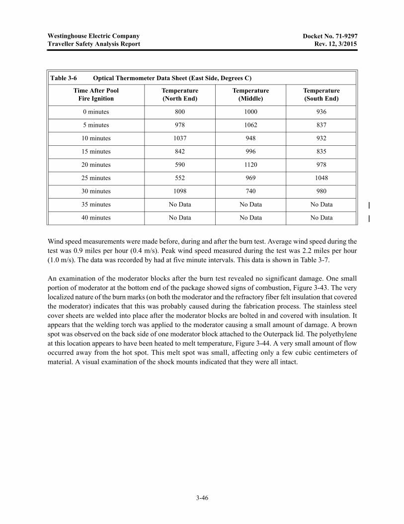
Westinghouse Electric CompanyTraveller Safety Analysis Report Rev. 12, 3/2015
Docket No. 71-9297
Wind speed measurements were made before, during and after the burn test. Average wind speed during thetest was 0.9 miles per hour (0.4 m/s). Peak wind speed measured during the test was 2.2 miles per hour(1.0 m/s). The data was recorded by had at five minute intervals. This data is shown in Table 3-7.
An examination of the moderator blocks after the burn test revealed no significant damage. One smallportion of moderator at the bottom end of the package showed signs of combustion, Figure 3-43. The verylocalized nature of the burn marks (on both the moderator and the refractory fiber felt insulation that coveredthe moderator) indicates that this was probably caused during the fabrication process. The stainless steelcover sheets are welded into place after the moderator blocks are bolted in and covered with insulation. Itappears that the welding torch was applied to the moderator causing a small amount of damage. A brownspot was observed on the back side of one moderator block attached to the Outerpack lid. The polyethyleneat this location appears to have been heated to melt temperature, Figure 3-44. A very small amount of flowoccurred away from the hot spot. This melt spot was small, affecting only a few cubic centimeters ofmaterial. A visual examination of the shock mounts indicated that they were all intact.
Table 3-6 Optical Thermometer Data Sheet (East Side, Degrees C)
Time After Pool Fire Ignition
Temperature(North End)
Temperature(Middle)
Temperature(South End)
0 minutes 800 1000 936
5 minutes 978 1062 837
10 minutes 1037 948 932
15 minutes 842 996 835
20 minutes 590 1120 978
25 minutes 552 969 1048
30 minutes 1098 740 980
35 minutes No Data No Data No Data
40 minutes No Data No Data No Data
3-46
Westinghouse Electric CompanyTraveller Safety Analysis Report Rev. 1, 11/2004
Docket No. 71-9297
Ultra-high molecular weight (UHMW) polyethylene was selected as the neutron moderator for the Travellerpackage because of its high hydrogen content, its ductility at very low temperatures and its high viscosityat temperatures well above its melt point due to the long molecular chains (MW=3,000,000 to 6,000,000).The relative solution viscosity as measured by ASTM D4020 must be greater than 1.41 and is typicallyfound to be 2.3 to 3.5 dl/gm2 (at 135°C). As a result, UHMW polyethylene does not liquefy above its melttemperature and molded UHMW polyethylene parts are typically made at relatively high temperatures(190°–200°C) and very high pressures (70-100 bar)3. Its excellent stability allows it to be used in someapplications at temperatures as high as 450°C4. Experience in the Traveller test program has shown that thematerial will soften but not run, even when heated to near vaporization temperature (349°C). However, theTraveller design encapsulates the moderator with stainless steel. This is primarily done to prevent oxygenfrom reaching the moderator, should it reach vaporization temperature, but it does serve a secondaryfunction of ensuring that the moderator does not significantly distort or flow at high temperatures.
The highest measured temperature inside the package was 171°C which is lower that the typical processtemperature used to create the UHMW sheets installed in the Traveller. Unchanged appearance and moreimportantly, unchanged weight indicate that the plastic did not loose a significant amount of its hydrogenduring the test.
1. Stein, H.L., “Ultra High Molecular Weight Polyethylene (UHMWPE),” Engineered Materials Handbook, Vol. 2, Engineering Plastics, 1998.
2. This is a typical value observed in many manufacturers specifications: Crown Plastics (crownplastics.com/ properties.htm).
3. Ticona Engineering Polymers information on compression molding, www.ticona.com/index/tech/processing/ compression_molding/gur1.htm.
4. Stein, H.L., “Ultra High Molecular Weight Polyethylene (UHMWPE),” Engineered Materials Handbook, Vol. 2, Engineering Plastics, 1998
3-46A
Westinghouse Electric CompanyTraveller Safety Analysis Report Rev. 1, 11/2004
Docket No. 71-9297
This page intentionally left blank.
3-46B
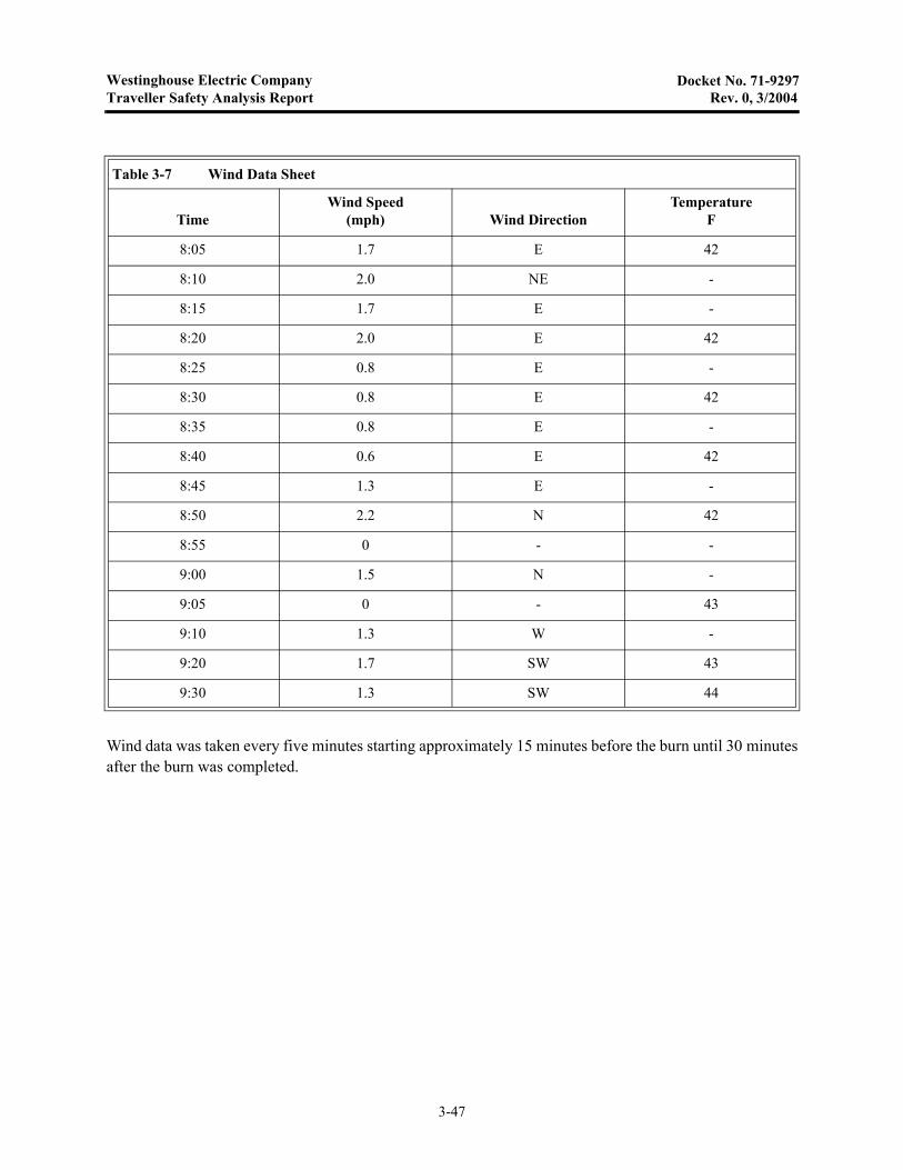
Westinghouse Electric CompanyTraveller Safety Analysis Report Rev. 0, 3/2004
Docket No. 71-9297
Wind data was taken every five minutes starting approximately 15 minutes before the burn until 30 minutesafter the burn was completed.
Table 3-7 Wind Data Sheet
TimeWind Speed
(mph) Wind DirectionTemperature
F
8:05 1.7 E 42
8:10 2.0 NE -
8:15 1.7 E -
8:20 2.0 E 42
8:25 0.8 E -
8:30 0.8 E 42
8:35 0.8 E -
8:40 0.6 E 42
8:45 1.3 E -
8:50 2.2 N 42
8:55 0 - -
9:00 1.5 N -
9:05 0 - 43
9:10 1.3 W -
9:20 1.7 SW 43
9:30 1.3 SW 44
3-47
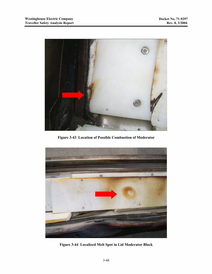
Westinghouse Electric CompanyTraveller Safety Analysis Report Rev. 0, 3/2004
Docket No. 71-9297
Figure 3-43 Location of Possible Combustion of Moderator
Figure 3-44 Localized Melt Spot in Lid Moderator Block
3-48
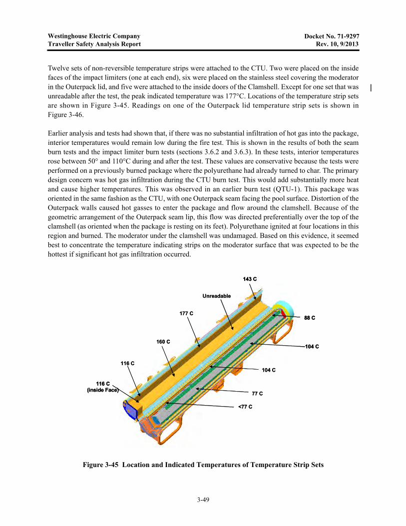
Westinghouse Electric CompanyTraveller Safety Analysis Report Rev. 10, 9/2013
Docket No. 71-9297
Twelve sets of non-reversible temperature strips were attached to the CTU. Two were placed on the insidefaces of the impact limiters (one at each end), six were placed on the stainless steel covering the moderatorin the Outerpack lid, and five were attached to the inside doors of the Clamshell. Except for one set that wasunreadable after the test, the peak indicated temperature was 177°C. Locations of the temperature strip setsare shown in Figure 3-45. Readings on one of the Outerpack lid temperature strip sets is shown inFigure 3-46.
Earlier analysis and tests had shown that, if there was no substantial infiltration of hot gas into the package,interior temperatures would remain low during the fire test. This is shown in the results of both the seamburn tests and the impact limiter burn tests (sections 3.6.2 and 3.6.3). In these tests, interior temperaturesrose between 50° and 110°C during and after the test. These values are conservative because the tests wereperformed on a previously burned package where the polyurethane had already turned to char. The primarydesign concern was hot gas infiltration during the CTU burn test. This would add substantially more heatand cause higher temperatures. This was observed in an earlier burn test (QTU-1). This package wasoriented in the same fashion as the CTU, with one Outerpack seam facing the pool surface. Distortion of theOuterpack walls caused hot gasses to enter the package and flow around the clamshell. Because of thegeometric arrangement of the Outerpack seam lip, this flow was directed preferentially over the top of theclamshell (as oriented when the package is resting on its feet). Polyurethane ignited at four locations in thisregion and burned. The moderator under the clamshell was undamaged. Based on this evidence, it seemedbest to concentrate the temperature indicating strips on the moderator surface that was expected to be thehottest if significant hot gas infiltration occurred.
Figure 3-45 Location and Indicated Temperatures of Temperature Strip Sets
116 C(inside Face)
116 C
160 C
177 C
Unreadable
143 C
<77 C
77 C
104 C
104 C
88 C
116 C(inside Face)
116 C
160 C
177 C
Unreadable
143 C
<77 C
77 C
104 C
104 C
88 C
116 C(inside Face)
116 C
160 C
177 C
Unreadable
143 C
<77 C
77 C
104 C
104 C
88 C
3-49

Westinghouse Electric CompanyTraveller Safety Analysis Report Rev. 1, 11/2004
Docket No. 71-9297
Figure 3-46 Temperature Strip Set After Fire Test
3-50