Western Renewable Energy Zones, Phase 1: QRA ... Report NREL/SR-6A2-46877 October 2009 Western...
159
Subcontract Report NREL/SR-6A2-46877 October 2009 Western Renewable Energy Zones, Phase 1: QRA Identification Technical Report Ryan Pletka and Josh Finn Black & Veatch Corporation Overland Park, Kansas
Transcript of Western Renewable Energy Zones, Phase 1: QRA ... Report NREL/SR-6A2-46877 October 2009 Western...
Subcontract Report NREL/SR-6A2-46877 October 2009
Western Renewable Energy Zones, Phase 1: QRA Identification Technical Report Ryan Pletka and Josh Finn Black & Veatch Corporation Overland Park, Kansas
National Renewable Energy Laboratory 1617 Cole Boulevard, Golden, Colorado 80401-3393 303-275-3000 • www.nrel.gov
NREL is a national laboratory of the U.S. Department of Energy Office of Energy Efficiency and Renewable Energy Operated by the Alliance for Sustainable Energy, LLC
Contract No. DE-AC36-08-GO28308
Subcontract Report NREL/SR-6A2-46877 October 2009
Western Renewable Energy Zones, Phase 1: QRA Identification Technical Report Ryan Pletka and Josh Finn Black & Veatch Corporation Overland Park, Kansas
NREL Technical Monitor: David Hurlbut Prepared under Subcontract No. AXL-8-88300-01
Principal Investigators: Ryan Pletka, Project Manager Derek Djeu Carlos De Leon Josh Finn Kevin Gilton Adam Hanna Cristin Holmgren Kevin Joyce Jagmeet Khangura Sally Maki Dennis Noll Scott Olson Mary Sprouse

NOTICE
This report was prepared as an account of work sponsored by an agency of the United States government. Neither the United States government nor any agency thereof, nor any of their employees, makes any warranty, express or implied, or assumes any legal liability or responsibility for the accuracy, completeness, or usefulness of any information, apparatus, product, or process disclosed, or represents that its use would not infringe privately owned rights. Reference herein to any specific commercial product, process, or service by trade name, trademark, manufacturer, or otherwise does not necessarily constitute or imply its endorsement, recommendation, or favoring by the United States government or any agency thereof. The views and opinions of authors expressed herein do not necessarily state or reflect those of the United States government or any agency thereof.
Available electronically at http://www.osti.gov/bridge
Available for a processing fee to U.S. Department of Energy and its contractors, in paper, from:
U.S. Department of Energy Office of Scientific and Technical Information P.O. Box 62 Oak Ridge, TN 37831-0062 phone: 865.576.8401 fax: 865.576.5728 email: mailto:[email protected]
Available for sale to the public, in paper, from: U.S. Department of Commerce National Technical Information Service 5285 Port Royal Road Springfield, VA 22161 phone: 800.553.6847 fax: 703.605.6900 email: [email protected] online ordering: http://www.ntis.gov/ordering.htm
This publication received minimal editorial review at NREL
Printed on paper containing at least 50% wastepaper, including 20% postconsumer waste

Table of Contents
TC-1
Table of Contents
1.0 Executive Summary ................................................................................................... 1-1 1.1 Development of WREZ QRA Identification Methodology ................................. 1-1 1.2 Identification of Qualified Resource Areas ......................................................... 1-2 1.3 Economic Analysis of QRAs ............................................................................... 1-2
2.0 Introduction ................................................................................................................ 2-1 2.1 Background .......................................................................................................... 2-1 2.2 Objective .............................................................................................................. 2-4 2.3 Approach .............................................................................................................. 2-5 2.4 Report Organization ............................................................................................. 2-5 2.5 Data Sources ........................................................................................................ 2-5 2.6 Use and Purpose of this Report ............................................................................ 2-8
3.0 Methodology and Assumptions ................................................................................. 3-1 3.1 QRA Development Process ................................................................................. 3-1
3.1.1 Resource Characterization .......................................................................... 3-1 3.1.2 Candidate Study Areas ................................................................................ 3-2 3.1.3 QRA Identification...................................................................................... 3-5
3.2 Technical and Environmental Exclusion Areas ................................................... 3-5 3.2.1 Resource Quality, Technical and Land Use Exclusions ............................. 3-5 3.2.2 Developability Screening ............................................................................ 3-6 3.2.3 Environmental Exclude and Avoid Areas ................................................... 3-9 3.2.4 Removing Exclusion Areas ....................................................................... 3-10
3.3 Qualified Resource Area Identification ............................................................. 3-12 3.3.1 Grid Square Analysis ................................................................................ 3-13 3.3.2 QRA Selection .......................................................................................... 3-17
3.4 Economic Analysis of QRAs ............................................................................. 3-19 3.4.1 Generation Cost ........................................................................................ 3-19 3.4.2 Financial Assumptions .............................................................................. 3-23
3.5 Renewable Energy Financial Incentives ............................................................ 3-24 3.5.1 U.S. Federal Government ......................................................................... 3-24 3.5.2 State Financial Incentives ......................................................................... 3-27 3.5.3 Canadian Incentives .................................................................................. 3-27 3.5.4 Mexican Incentives ................................................................................... 3-27 3.5.5 Future Term and Nature of Incentives ...................................................... 3-28
3.6 Non-REZ Resources .......................................................................................... 3-28

Table of Contents
TC-2
4.0 Resource Characterization ......................................................................................... 4-1 4.1 Biomass ................................................................................................................ 4-1
4.1.1 Resource Assessment Methodology ........................................................... 4-1 4.1.2 Resource Supply Curve Characteristics ...................................................... 4-7 4.1.3 Results ......................................................................................................... 4-8 4.1.4 Non-REZ Resources ................................................................................. 4-10 4.1.5 Data Sources ............................................................................................. 4-11
4.2 Geothermal ......................................................................................................... 4-12 4.2.1 Resource Assessment Methodology ......................................................... 4-12 4.2.2 Resource Supply Curve Characteristics .................................................... 4-15 4.2.3 Results ....................................................................................................... 4-17 4.2.4 Non-REZ Resources ................................................................................. 4-18 4.2.5 Data Sources ............................................................................................. 4-20
4.3 Hydropower ....................................................................................................... 4-22 4.3.1 Resource Assessment Methodology ......................................................... 4-22 4.3.2 Resource Supply Curve Characteristics .................................................... 4-26 4.3.3 Results ....................................................................................................... 4-27 4.3.4 Non-REZ Resources ................................................................................. 4-30 4.3.5 Data Sources ............................................................................................. 4-31
4.4 Solar ................................................................................................................... 4-33 4.4.1 Resource Assessment Methodology ......................................................... 4-33 4.4.2 Resource Supply Curve Characteristics .................................................... 4-36 4.4.3 Results ....................................................................................................... 4-40 4.4.4 Non-REZ Resources ................................................................................. 4-42 4.4.5 Data Sources ............................................................................................. 4-44
4.5 Wind ................................................................................................................... 4-46 4.5.1 Resource Assessment Methodology ......................................................... 4-47 4.5.2 Resource Supply Curve Characteristics .................................................... 4-51 4.5.3 Results ....................................................................................................... 4-53 4.5.4 Non-REZ Resources ................................................................................. 4-55 4.5.5 Data Sources ............................................................................................. 4-56
5.0 QRA and Non-REZ Analysis Results ........................................................................ 5-1 5.1 QRA Maps ........................................................................................................... 5-1
5.1.1 WREZ QRA Map ....................................................................................... 5-1 5.1.2 WREZ Hub Map ......................................................................................... 5-4
5.2 Summary of QRA Analysis Results .................................................................... 5-6 5.2.1 Resource Analysis ....................................................................................... 5-6

Table of Contents
TC-3
5.2.2 Economic Analysis ..................................................................................... 5-7 5.3 Summary of Non-REZ Resource Analysis Results ............................................. 5-9
Appendices
Appendix A. QRA-Level Supply Curves
Appendix B. QRA Capacity and Energy Summary Tables
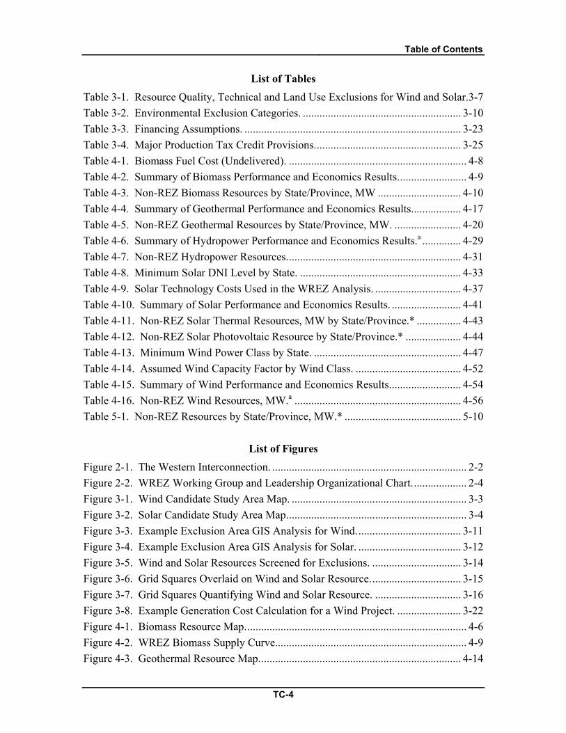
Table of Contents
TC-4
List of Tables Table 3-1. Resource Quality, Technical and Land Use Exclusions for Wind and Solar. 3-7 Table 3-2. Environmental Exclusion Categories. ......................................................... 3-10 Table 3-3. Financing Assumptions. .............................................................................. 3-23 Table 3-4. Major Production Tax Credit Provisions. .................................................... 3-25 Table 4-1. Biomass Fuel Cost (Undelivered). ................................................................ 4-8 Table 4-2. Summary of Biomass Performance and Economics Results. ........................ 4-9 Table 4-3. Non-REZ Biomass Resources by State/Province, MW .............................. 4-10 Table 4-4. Summary of Geothermal Performance and Economics Results. ................. 4-17 Table 4-5. Non-REZ Geothermal Resources by State/Province, MW. ........................ 4-20 Table 4-6. Summary of Hydropower Performance and Economics Results.a .............. 4-29 Table 4-7. Non-REZ Hydropower Resources. .............................................................. 4-31 Table 4-8. Minimum Solar DNI Level by State. .......................................................... 4-33 Table 4-9. Solar Technology Costs Used in the WREZ Analysis. ............................... 4-37 Table 4-10. Summary of Solar Performance and Economics Results. ......................... 4-41 Table 4-11. Non-REZ Solar Thermal Resources, MW by State/Province.* ................ 4-43 Table 4-12. Non-REZ Solar Photovoltaic Resource by State/Province.* .................... 4-44 Table 4-13. Minimum Wind Power Class by State. ..................................................... 4-47 Table 4-14. Assumed Wind Capacity Factor by Wind Class. ...................................... 4-52 Table 4-15. Summary of Wind Performance and Economics Results. ......................... 4-54 Table 4-16. Non-REZ Wind Resources, MW.a ............................................................ 4-56 Table 5-1. Non-REZ Resources by State/Province, MW.* .......................................... 5-10
List of Figures Figure 2-1. The Western Interconnection. ...................................................................... 2-2 Figure 2-2. WREZ Working Group and Leadership Organizational Chart. ................... 2-4 Figure 3-1. Wind Candidate Study Area Map. ............................................................... 3-3 Figure 3-2. Solar Candidate Study Area Map. ................................................................ 3-4 Figure 3-3. Example Exclusion Area GIS Analysis for Wind. ..................................... 3-11 Figure 3-4. Example Exclusion Area GIS Analysis for Solar. ..................................... 3-12 Figure 3-5. Wind and Solar Resources Screened for Exclusions. ................................ 3-14 Figure 3-6. Grid Squares Overlaid on Wind and Solar Resource. ................................ 3-15 Figure 3-7. Grid Squares Quantifying Wind and Solar Resource. ............................... 3-16 Figure 3-8. Example Generation Cost Calculation for a Wind Project. ....................... 3-22 Figure 4-1. Biomass Resource Map. ............................................................................... 4-6 Figure 4-2. WREZ Biomass Supply Curve..................................................................... 4-9 Figure 4-3. Geothermal Resource Map. ........................................................................ 4-14
Table of Contents
TC-5
Figure 4-4. Plant Output vs. Ambient Temperature ..................................................... 4-16 Figure 4-5. WREZ Geothermal Supply Curve. ............................................................ 4-18 Figure 4-6. Hydropower Resource Map. ...................................................................... 4-25 Figure 4-7. WREZ Hydropower Supply Curve. ........................................................... 4-30 Figure 4-8. Solar Resource Map. .................................................................................. 4-35 Figure 4-9. Example Energy Output from Tracking Crystalline and Fixed Tilt Thin Film
(July). ............................................................................................................ 4-39 Figure 4-10. Example Energy Output from Tracking Crystalline and Fixed Tilt Thin
Film (December). ......................................................................................... 4-39 Figure 4-11. WREZ Solar Capacity by State/Province and DNI Level. ...................... 4-40 Figure 4-12. WREZ Solar Thermal Supply Curve. ...................................................... 4-42 Figure 4-13. Wind Resource Map. ................................................................................ 4-50 Figure 4-14. WREZ Wind Capacity by State/Province and Wind Power Class. ......... 4-53 Figure 4-15. WREZ Wind Supply Curve. .................................................................... 4-55 Figure 5-1. WREZ QRA Map. ........................................................................................ 5-3 Figure 5-2. WREZ Hub Map. ......................................................................................... 5-5 Figure 5-3. WREZ Renewable Energy Capacity by State/Province. .............................. 5-6 Figure 5-4. WREZ Annual Renewable Energy Generation by State/Province. ............. 5-7 Figure 5-5. BC_NE QRA Supply Curve......................................................................... 5-8 Figure 5-6. Non-REZ Resources by State/Province. .................................................... 5-11

1.0 Executive Summary
1-1
1.0 Executive Summary
Black & Veatch is pleased to provide this report on the Western Renewable Energy Zones (WREZ) initiative Phase 1 Qualified Resource Area identification process to the National Renewable Energy Laboratory. This report describes the identification and economic analysis of Qualified Resource Areas (QRAs) and “non-REZ” resources. These data and analyses will assist the Western US in its renewable energy transmission planning goals. The economic analysis in this report produced the input data for the WREZ Generation and Transmission model, which is a screening-level model to determine the optimal routing for and cost of delivering renewable energy from QRAs to load centers throughout the Western Interconnection.
This report is the final Black & Veatch deliverable for the Phase 1 portion of the WREZ initiative. In June 2009 the Western Governors’ Association accepted the Western Governors’ Association WREZ Phase 1 Report in which the QRAs were mapped and the entire WREZ Phase 1 process was explained in general. That same month the Lawrence Berkeley National Laboratory released the WREZ Generation and Transmission Model (GTM), which was also developed by Black & Veatch. This report details the assumptions and methodologies that were used to produce the maps and resource analyses in the WGA report as well as the economic data used by the WREZ GTM. This report also provides the results of the non-REZ resource analysis for the first time in the WREZ initiative.
1.1 Development of WREZ QRA Identification Methodology In Phase 1 of the WREZ initiative, QRAs were defined as areas of high quality
and dense renewable energy resources with enough capacity to potentially justify the construction of a high voltage transmission line for interstate transmission of renewable energy. QRAs needed to meet size, resource quality, environmental and technical criteria. The WREZ Zone Identification and Technical Analysis (ZITA) working group developed the economic and technical criteria to identify QRAs. The WREZ Environment & Lands (E&L) working group developed the environmental criteria to identify QRAs.
Black & Veatch used these two sets of criteria in geospatial analyses of the entire WREZ study area to filter vast renewable energy resource potential to the highest quality and most developable renewable energy resources. The resulting resource areas were called Candidate Study Areas (CSAs). The screening criteria developed by the ZITA and E&L working groups are detailed in Chapters 3.0 and 4.0 and maps of the CSAs are shown in Figure 3-1 and Figure 3-2.
1.0 Executive Summary
1-2
Fifty-three QRAs were identified across the WREZ study area, with nearly 200,000 MW of renewable energy resources theoretically capable of generating over 560 terawatt hours (TWh) of energy per year.1 Over 2,200,000 MW of non-REZ resources were also identified across the study area. To put these estimates in perspective, the entire WECC peak load in summer 2007 was 150,000 MW.2
1.2 Identification of Qualified Resource Areas Once the CSAs were identified, resources were grouped and analytical boundaries
were defined around them. The resources inside these boundaries were quantified and became the basis for WREZ QRAs. The resources that did not meet the WREZ resource criteria or fell outside QRA boundaries were counted as non-REZ resources and quantified separately.
The WREZ study identified nearly 200 GW of potential renewable energy resources within 53 QRAs in the WREZ study area and over 1,200 GW of non-REZ resource potential. Wind and solar constitute the majority of WREZ resources . Biomass, geothermal and hydropower also provide a significant amount of the cost-effective energy resources inside QRAs. The majority of the non-REZ resources are from solar photovoltaics and enhanced geothermal systems (EGS) resources.
A map of all the WREZ QRAs and qualifying WREZ resources, showing the final boundaries of QRAs as identified in the QRA analysis detailed in Chapter 3.0 is shown in Figure 5-1. Note that the QRA boundaries are analytical and not legal; they do not necessarily reflect areas that may be off limits to development due to local restrictions or because of site-specific environmental sensitivities. Capacity and energy summary tables by resource and by QRA are provided in Appendix B. Non-REZ resources identified across the WREZ study area are quantified in Table 5-1. The non-REZ analysis for each resource is detailed in Chapter 5.0.
1.3 Economic Analysis of QRAs Once QRAs were identified, the cost of generation was calculated for every
resource in every QRA as a levelized cost of generating power over the life of the resource on a $/MWh basis. These estimates exclude long-distance generation costs,
1 British Columbia provided a 54th QRA representing a shaped renewable energy product to load serving entities (LSEs) at the British Columbia-Washington border. This QRA is shown in the hub map and selectable in the GTM model. However, it was developed independently of the Black & Veatch/NREL QRA analysis outlined here, so it is not characterized here. 2 WREZ Zone Identification and Technical Analysis Working Group, Step 2: Filtering resource data into Candidate Study Areas, Available: http://www.westgov.org/wga/initiatives/wrez/zita/Step2.pdf, 2009.
1.0 Executive Summary
1-3
which are modeled and added in the GTM module. Performance, economic and financing assumptions were developed for each technology by the ZITA working group and Black & Veatch. These were used in a cost of generation model developed by Black & Veatch to create generation supply curves for all QRAs. These curves show the amount of annual energy generation theoretically available at a particular price point. Supply curves for all QRAs are shown in Appendix A.
The cost of energy varied among technologies and within each technology. There were many factors that contributed to this variation. However, the most significant driver of cost variation was variation in the quality of the renewable energy resources across different areas. In general, higher quality resources had lower costs per MWh.

2.0 Introduction
2-1
2.0 Introduction
Black & Veatch presents the WREZ Phase 1 Qualified Resource Area Identification Technical Report for the National Renewable Energy Laboratory (NREL). The objective of this report is to document the process used in the WREZ initiative to identify “Qualified Resource Areas” (QRAs), or areas with high concentrations of high quality renewable energy resources across the Western Interconnection. This introductory section includes some background to this initiative, a discussion of the objective of this report, its general analytical approach and the report’s organization.
2.1 Background Phase 1 of the Western Renewable Energy Zones (WREZ) study was undertaken
by NREL and the Western Governor’s Association (WGA) to identify areas of the Western Interconnection (Western Electricity Coordinating Council or WECC) that have both the potential for large scale development of renewable resources and low environmental impacts.3
The WREZ Charter sets forth the overarching objective of the WREZ project:
To develop transmission plans of service to priority zones to facilitate the environmentally sensitive development of the most cost-effective renewable resources located in the Western Interconnection. The project will evaluate all feasible renewable resource technologies that are likely to contribute to the realization of the goal in WGA policy resolution 6-10 for the development of 30,000 megawatts of clean and diversified energy by 2015, but may not include all such resources in the WREZ. The WREZ is intended to complement all the efforts related to implementing WGA policy, including development of a mix of clean and diverse energy resources and having a secure, reliable interstate transmission network that can move all generated electricity to markets.
3 Western Governor’s Association, Western Renewable Energy Zones Charter, Available: http://westgov.org/wga/initiatives/wrez/wrez-charter.pdf, May 2008
2.0 Introduction
2-2
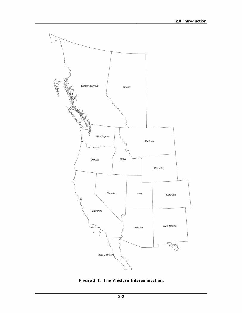
Figure 2-1. The Western Interconnection.

2.0 Introduction
2-3
Phase 1 of the study engaged a diverse range of stakeholders to make decisions about the study direction and the criteria used in the technical and economic analysis.
The followings states and provinces were part of this study
• Alberta • Arizona • Baja California Norte • British Columbia • California • Colorado • Idaho
• Montana • Nevada • New Mexico • Oregon • Texas (El Paso area) • Utah • Washington • Wyoming
Decisions were first approved by small technical working groups and then
reviewed and finalized by WREZ leadership committees. The working groups involved in the QRA identification process were the Environment & Lands (E&L) working group (in collaboration with the Western Governor’s Wildlife Council or WGWC) and the Zone Identification and Technical Analysis (ZITA) working group. Another working group, the Generation and Transmission Modeling working group created the WREZ Generation and Transmission Model (GTM), which is not described in depth here. The WREZ initiative leadership committees consisted of two levels: the WREZ Technical Committee, which was staffed by representatives from the states and provinces from each WREZ work group and from the range of stakeholders interested in energy issues in the West; and the WREZ Steering Committee, comprising governors of the 11 Western states within the Western Interconnection (or their designees), public utility commissioners from each of those states and the Premiers of British Columbia and Alberta.4
4 Western Governor’s Association, About the WREZ, Available:
http://westgov.org/wga/initiatives/wrez/index.htm, May 2008

2.0 Introduction
2-4
Figure 2-2. WREZ Working Group and Leadership Organizational Chart.5
Black & Veatch was retained to provide technical guidance and perform the analytical tasks necessary to identify and analyze the economics of renewable energy resources within the QRAs, which are precursors to Western Renewable Energy Zones. The WREZ Phase 1 report was approved by the WREZ Technical and Steering committees in late Spring 2009, and accepted by the Western Governor’s Association in June 2009.
Note that although the study was funded and undertaken by governmental agencies and leaders, it does not impinge on the legal authority or replace the regulatory role or requirements of any local, state, provincial, tribal or federal agency.6
2.2 Objective
This technical report describes the QRA and supply curve analyses and presents the results from these analyses in detail. The supply curve analysis performed by Black & Veatch was an input to the WREZ GTM, which calculates the cost of delivering renewable energy from QRAs to load centers throughout the west. The supply curve
5 Western Governor’s Association, About the WREZ, Available: http://westgov.org/wga/initiatives/wrez/index.htm, May 2008 6 Western Governor’s Association, Western Renewable Energy Zones - Phase 1 Report, Available: http://www.westgov.org/wga/publicat/WREZ09.pdf, June 2009

2.0 Introduction
2-5
analysis results shown in this report include the cost of generation plus the cost of delivering electricity from a QRA to the transmission system. The technical assumptions used in this analysis are documented in this report and also available in the original format documented by Black & Veatch for the ZITA working group on the project web site: http://westgov.org/wga/initiatives/wrez/zita/index.htm.
2.3 Approach The WREZ Phase 1 study analyzed the economics of 54 QRAs with potential for
high quality biomass, geothermal, hydropower, solar and/or wind energy generating potential across the WECC. These areas were identified after taking into account technical constraints (such as land slope) and minimum resource quality considerations developed by the ZITA working group. The identification and analysis of these areas also took into account environmental exclusions identified by the E&L working group and the WGWC. The Phase 1 study also quantified “non-REZ” resources: renewable energy resources that were of a lower quality and/or were located outside of the boundaries of the QRAs.
2.4 Report Organization Following this Introduction, this report is organized into the following sections: • Section 3 – Methodology and Assumptions: This section describes the
methodology and assumptions used to identify and analyze the economics of QRAs.
• Section 4 – Resource Characterization: The WREZ Phase 1 study identified nearly 200,000 MW of biomass, geothermal, hydropower, solar and wind resources in QRAs across the WREZ study area. This section discusses the methodology used to characterize these resources. It also presents the results of the non-REZ resource analysis.
• Section 5 – QRA and Non-REZ Analysis Results: 54 Qualified Resource Areas were identified in the WREZ analysis. This section presents the results of this analysis at the QRA level.
2.5 Data Sources Data sources used in this report include the following:
• California Energy Commission, An Assessment of Biomass Resources in California, PIER Collaborative Report 500-01-016, California Biomass Collaborative, 2006

2.0 Introduction
2-6
• Fuchs, Mark and Frear, Craig et al, Biomass Inventory and Bioenergy Assessment: An Evaluation of Organic Material Resources for Bioenergy Production in Washington State, Washington Department of Ecology, Available: http://www.ecy.wa.gov/biblio/0507047.html, 2005
• Personal communication with Matthew Good, Alberta Department of Energy, August 2009 • Macdonald, A.J., Inventory of Wood Biomass from Harvesting Residues and Non-
Merchantable Forests in Alberta, FPInnovations, November 2007. • Milbrandt, Anelia, A Geographic Perspective on the Current Biomass Resource
Availability in the United States, 2005, NREL Technical Report NREL/TP-560-39181. • National Land and Water Information Service, Biomass Inventory and Mapping Tool,
Agriculture and Agri-Food Canada, Available: http://www4.agr.gc.ca/AAFC-AAC/display-afficher.do?id=1226509218872&lang=eng, April 2009
• Western Governor’s Association Biomass Task Force, Strategic Assessment of Bioenergy Development in the West, Available: http://westgov.org/wga/initiatives/transfuels/index.html, 2008
• BC Hydro, Green Energy Study for British Columbia; Phase 2: Mainland, Report No. E44. Chapter 5.2: Geothermal Energy, pp. 18-22, 2002
• Broad-based assessments of geothermal potential (such as the USGS assessment of 1979, currently being updated; the CEC-PIER report of 2004; the WGA study of 2006)
• Data cited in a Personal Communication between Alison Thompson at the Canadian Geothermal Energy Association and the Western Governor’s Association, February 2009
• Fairbank, B. D., and R. I. Faulkner, Geothermal resources of British Columbia. Geological Survey of Canada, Open File 2526, 1992
• Personal communications with Jacob DeAngelo at the USGS on November 10, 2008 • Personal communication with Sue Bonnyman at the BC Ministry of Energy, Mines
and Petroleum on November 1, 2008 • Government of British Columbia (2007). Geothermal resources map.
http://www.em.gov.bc.ca/Geothermal/GeothermalResourcesMap.htm • Southern Methodist University, Western Geothermal Areas Database, Available:
http://smu.edu/geothermal/georesou/resource.htm, 2008 • Ralevic, Peter and Layzell, David B., An Inventory of the Bioenergy Potential of
British Columbia, BIOCAP Canada Foundation, November 2006 • Williams, Colin F., Reed, Marshall J., Mariner, Robert H., DeAngelo, Jacob, Galanis,
S. Peter, Jr., Assessment of Moderate- and High-Temperature Geothermal Resources of the United States: U.S. Geological Survey Fact Sheet 2008-3082, 2008

2.0 Introduction
2-7
• Kutscher, C., Cosentaro, D. “Assessment of Evaporative Cooling Enhancement Methods for Air-Cooled Geothermal Power Plants.” Presented at the Geothermal Resources Council Annual Meeting, Reno, NV. September 22-25, 2002. NREL/CP-550-23294.
• NREL TMY2 Data, Available at: http://rredc.nrel.gov/solar/old_data/nsrdb/tmy2/ • BC Hydro, 2008 Long Term Acquisition Plan Appendix F1 Resource Options
Database (RODAT) Sheets, Available: http://www.bchydro.com/etc/medialib/internet/documents/info/pdf/ 2008_ltap_appendix_f8.Par.0001.File.2008_ltap_appendix_f8.pdf, 2008
• Engineering News Record, Building Cost Index History, Available: http://enr.ecnext.com/coms2/article_echi090601bldIndexHist, 2009
• Idaho National Laboratory, Estimation of Economic Parameters of U.S. Hydropower, Available: http://hydropower.inl.gov/resourceassessment/index.shtml, 2003
• Kerr Wood Leidal Associates Ltd., Run-of-River Hydroelectric Resource Assessment for British Columbia, Available: http://www.bchydro.com/etc/medialib/internet/documents/info/pdf/ 2008_ltap_appendix_f5.Par.0001.File.2008_ltap_appendix_f5.pdf, 2007
• Personal communication with Edward Higginbottom, Senior Strategy Advisor, British Columbia Transmission Corporation, January 2009
• Personal communication with Bevan Laing, Senior Manager, Generation, Infrastructure Policy, Government of Alberta Department of Energy, May 2009
• Personal Communication with Edward Higginbottom, Senior Strategy Advisor, British Columbia Transmission Corporation and Allan Woo, BC Hydro, February 2009
• Personal communication with Kathy Lee, Senior Resource Planning Engineer, BC Hydro, February 2009
• Western Governor’s Association, WREZ Technology Assumptions for Supply Curve Analysis, Available: http://westgov.org/wga/initiatives/wrez/zita/Technology%20Assumption%20-%20Supply%20Curve%20TCversion.pdf, January 2009
• Blair, et.al., Modeling Photovoltaic and Concentrating Solar Power Trough Performance, Cost, and Financing with the Solar Advisor Model, available: www.nrel.gov, accessed: June 2008.
• R. Bird and C. Riordan, Simple Spectral Model for Direct and Diffuse Irradiance on Horizontal and Tilted Planes at the Earth's Surface for Cloudless Atmospheres, available at: www.nrel.gov, accessed: June 2008.
• Perez, et.al., SUNY Satellite Solar Radiation model, available at: www.nrel.gov, accessed: June 2008.

2.0 Introduction
2-8
• NREL’s GIS team, High Resolution National Solar Photovoltaic and Solar Thermal GIS data, available at: www.nrel.gov, accessed: June 2008.
• NREL Wind Resource Maps, available at: http://www.eere.energy.gov/windandhydro/windpoweringamerica/wind_maps.asp, accessed: March 6th, 2008
• NREL Mesoscale Wind Data, Available: mercator.nrel.gov/wwsi/
• BC Hydro, BC Wind Data Study, Available: http://www.bchydro.com/planning_regulatory/energy_technologies/wind_energy/wind_data_study.html, May 2009
• CanWEA and SEED, SE Area Wind Power Projects – Transmission Connected, received from Claude Mindorff or Mainstream Energy, November 2008.
2.6 Use and Purpose of this Report The WREZ Phase 1 Qualified Resource Area Identification Technical Report is
not a resource assessment. This report identifies areas of the WECC that might qualify as Western Renewable Energy Zones. This analysis was based on very specific criteria developed for the WREZ initiative. As such, the WREZ data are not recommended for direct use in other analyses and caution must be used when they are used for other purposes. The data produced by this study are not appropriate for site-level analysis. The data in this study might not even be appropriate for other high level planning studies, depending on the goals of the study.
Many simplifying assumptions went into the WREZ study that make the data inappropriate for other analyses. For example wind capacity factors were averaged across very large areas. A single capacity factor was assigned to all wind potential in each NREL wind power class 3 through 7. The weighted average of these capacity factors was calculated for areas of land in QRAs and the resulting capacity factor was assigned to all of the wind resources in those areas. This methodology tends to flatten out the variability in wind capacity factors across the QRAs. Low and high capacity factor wind resources that might exist in the QRAs are not captured by this methodology and the variation in generation cost among wind resources is relatively small. This methodology works well for zone identification and high-level transmission planning, but it is inappropriate to compare the capacity factors calculated in this analysis to the capacity factors of specific planned or existing projects in the same areas.

3.0 Methodology and Assumptions
3-1
3.0 Methodology and Assumptions
This section describes the methodology Black & Veatch used to identify QRAs, quantify the resources inside their boundaries, and calculate the cost of generating and delivering energy to the transmission system. The general guidelines and specific assumptions to be used in this methodology were developed by the ZITA and E&L stakeholder working groups, with guidance from Black & Veatch, NREL and others.
3.1 QRA Development Process QRAs are areas of high quality and dense renewable energy resources, which
have enough resources to potentially justify the construction of a high voltage transmission line for interstate transmission of renewable energy. QRAs must meet a number of specific size, resource quality and environmental and technical criteria, which are detailed below.
QRAs were identified based on the location, density and size of renewable energy resources across the WREZ study area. For some resources, QRA identification involved paring down large-scale, raw resource data to just the developable areas and selecting the best areas from among them. This was the general process for wind, solar and biomass, for which renewable resource data were available for the entire study area. When large-scale, raw resource data were not available, project-specific data were available. In these cases, these data were assumed to represent the developable resource potential for a resource, and were used to determine the extent of the QRAs. This was the general process for geothermal and hydropower across the study area as well as wind in Canada, for which appropriate large scale resource assessments were not available but assessments of specific potential projects were available.
3.1.1 Resource Characterization The first step in the QRA development process was to identify a set of qualifying
renewable energy resources. The ZITA group chose renewable energy resources of a large enough magnitude, high enough quality and dense enough dispersion to potentially justify the construction of a 500 kilovolt (kV) transmission line to transport energy across state/provincial lines. The specific criteria for each renewable energy resource considered are described in Chapter 4.0.
A parallel process was undertaken by ZITA, E&L and the WGWC working groups to identify all areas where renewable energy development cannot or should not occur, according to the guidance provided by the working groups. These environmental and technical exclusions were combined using GIS software and these exclusion areas

3.0 Methodology and Assumptions
3-2
were removed from the renewable resource datasets when applicable. This exclusion process was iterative and continued throughout the QRA analysis as new data became available and working group decisions about exclusion areas changed.
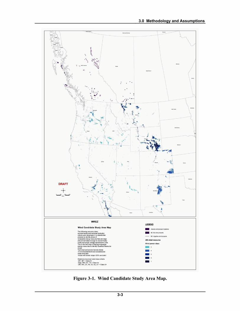
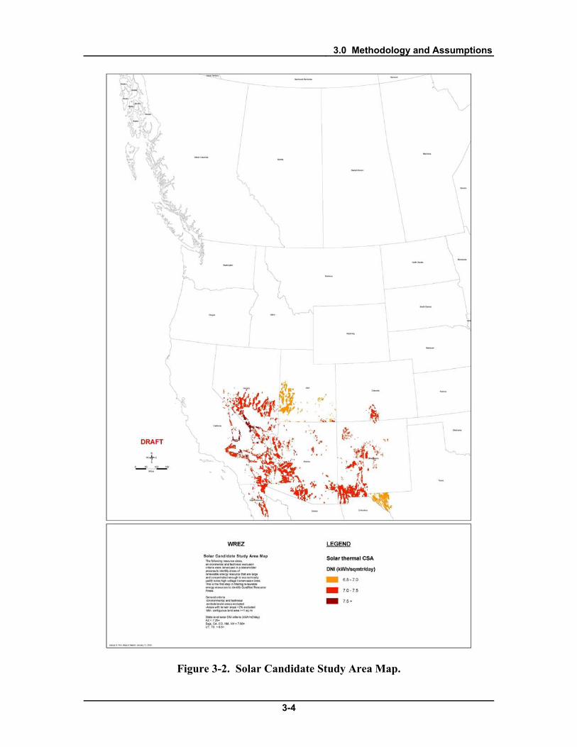
3.1.2 Candidate Study Areas The qualifying solar and wind resources identified resulted in areas that were too
large to analyze from a transmission perspective. These large areas were reduced to areas with only the highest quality resources. This process resulted in “Candidate Study Areas” (CSAs), and “ensured the identification of the best resources available for use on a regional scale and to meet more localized needs.”7
Resource quality criteria were applied to wind and solar to generate CSAs. For wind and solar resources in the US, the wind power classes considered varied by state. Given the variations in wind power classes and solar DNI levels among states in the Western Interconnection, it was determined that the best quality resources of each resource type would be identified in each state and serve as the minimum resource class identified in that state in the analysis. These thresholds are discussed further in Chapter 4.0. The WREZ CSA maps for wind and solar are shown below.
7 Western Governor’s Association, WREZ-Zone Identification and Technical Analysis, Available: http://westgov.org/wga/initiatives/wrez/zita/index.htm, January 2009.
3.0 Methodology and Assumptions
3-3
Figure 3-1. Wind Candidate Study Area Map.
3.0 Methodology and Assumptions
3-4
Figure 3-2. Solar Candidate Study Area Map.

3.0 Methodology and Assumptions
3-5
Resource quality criteria were also applied to the other resources assessed in WREZ. For biomass, only certain types of biomass feedstocks were considered. For geothermal, resource quality screening was done to generate the data provided to the WREZ process by GeothermEx. For hydropower, only certain types of potential projects were considered and screened out of the data. These resource quality thresholds and the resource subtypes considered are discussed further in Chapter 4.0.
3.1.3 QRA Identification Once the CSAs were identified and the exclusion areas were removed, resources
were grouped and boundaries were defined around them. Resources were grouped based on minimum and maximum QRA size criteria developed by the ZITA working group. According to the ZITA working group, a QRA had to be less than 100 miles across and have at least 1,500 MW of developable potential (500 MW for biomass, geothermal and Canadian resources). QRA size criteria are discussed in greater depth below.
3.2 Technical and Environmental Exclusion Areas Black & Veatch used a series of exclusion screens to filter out land and resources
that would not be appropriate for development and should not be part of the WREZ resource analysis. Technical and land use exclusion areas were defined by the ZITA working group. Environmental exclusion areas were defined by E&L and WGWC working groups.
It is important to note that the purpose of these exclusions was for QRA identification and not to recommend specific project siting and land use decisions. Also, it should not be assumed that areas where there are no exclusions are appropriate for siting plants. All actual project development will need to proceed through all local, state, and federal permitting processes; WREZ does not supersede judgments to be made by these authorities. Additionally, much of the land identified as part of this assessment is privately owned. WREZ does not intend to interfere with the decisions of private land owners in any manner.
3.2.1 Resource Quality, Technical and Land Use Exclusions The ZITA group developed technical, land use exclusions as well as resource
subtype and quality criteria. The technical and land use exclusions only applied to only wind and solar resources in the US. Biomass, geothermal, hydropower and Canadian wind resources across the WECC were identified using data produced in other studies.8
8 See Chapter 4.0 for the sources of all resource data.

3.0 Methodology and Assumptions
3-6
The exclusions applied to wind and solar either did not apply to these resources, or it was determined that these studies took into account technical and land use exclusions comparable to those applied to wind and solar resources in the US. The technical and land use exclusions applied to wind and solar in the US included highly sloped areas, urban areas, water bodies, areas with a very small contiguous area for solar as well as some military lands.
Military installations were excluded from consideration for wind and solar, after much discussion among ZITA group stakeholders. Originally, certain military flyways were considered to be exclusion areas for wind and solar because it was presumed that project development in these areas was precluded by law. However, after discussion with military representatives it was determined that it was appropriate to exclude military installations but not military flyways because development in these areas is not precluded by law.
3.2.2 Developability Screening It was reasonable to expect that not all of the resource within a given area can
actually be developed. Various constraints, such as land ownership, presence of structures, local zoning restrictions or other factors will limit the “developability” of even the most high quality resources. For this reason, various developability screens were applied to the resources to account for the likelihood that within any area, only a portion of the total resource potential is developable. The application of these discounts also created margin of safety that significantly increases the likelihood that WREZs will realize sufficient development to justify a high capacity transmission line.
In some cases, it was possible to estimate developability screens and discounts for different areas or sites based on the specific factors affecting the developability of each resource. In other cases this level of analysis was not possible given the scope of the study and broad developability discounts were applied to screened resource potential. Developability screens and discounts are discussed below and in further depth in Chapter 4.0.
Wind and Solar The developability of wind and solar in specific areas could not be studied in
WREZ given the screening level of the study and the vast areas with high quality wind and solar resources. To account for unknown and unpredictable developability constraints, it was assumed that only a fraction of all the land with wind and solar resource potential in the US would be developable. These percentages were estimated by the ZITA working group, and wind and solar resource potentials were discounted to those

3.0 Methodology and Assumptions
3-7
percents. For wind, it was assumed that 25 percent of the screened area would be developable. This discount for was based on industry experience from other regional wind studies. For solar, it was assumed that 3.5 percent of the land would be developable. Given the lack of industry experience and empirical data on the percentage of potential solar projects that are actually developed, this was chosen somewhat arbitrarily through consensus of the ZITA working group stakeholders.9
Wind and solar are the two largest renewable energy sources in the WREZ study and they are the only resources that were pared down from raw resource data based on explicit technical, environmental, resource quality and developability screens. The resource quality, technical and land use screens for these two resources area summarized below.
Table 3-1. Resource Quality, Technical and Land Use Exclusions for Wind and Solar.
Solar Wind Resource quality Varies by state Varies by state Terrain slope (percent) Greater than 2 Greater than 20 Min. contiguous square acres 640 N/A Water bodies Yes Yes Urban areas Yes Yes Military restrictions Installations excluded Installations excluded Percent of land developable 3.5 25 Source: WREZ ZITA working group, Available: http://westgov.org/wga/initiatives/wrez/zita/index.htm
Biomass Different developability discounts were applied to biomass resources, dependent
on the nature of the feedstock data. For biomass feedstock data that was not screened based on cost, it was assumed that only one third of the available biomass resources across the WECC could be used for power generation. This estimate was developed in previous Black & Veatch work, as part of the California Renewable Energy Transmission
9 While 3.5 percent is an arbitrary percentage, it does result in resource densities (MW/sqmi) that are comparable to the discounted wind potential. Further, the QRA sizes based on a 3.5 percent discount are typical several GW, which seems to be an appropriate scale to represent opportunities for large-scale transmission.

3.0 Methodology and Assumptions
3-8
Initiative.10 This estimate is also supported by analyses by NREL and state agencies and was vetted with biomass industry stakeholders in WREZ.11,12
For some biomass feedstocks a collection cost supply curve was available, based on the amount of biomass available at various price points. For these feedstocks, it was determined that all biomass resources of the types considered that cost $80/dry ton or less to collect would be assessed. This was determined to be the maximum collection cost acceptable by plant developers.
Geothermal Estimation of the amount of electricity that could be generated at various
geothermal sites was based on industry experience and applied to estimates of the heat that can be recovered as electrical energy from a site. Uncertainty was handled by a probabilistic approach that yielded a range of possible generation values and associated probabilities. The modal value of the probability distribution was considered the “most likely value” of generation potential for the project concerned. This assessment of the developable geothermal potential was carried out for Black & Veatch for the WREZ study by a subcontractor, GeothermEx.
Hydropower Three approaches to developability discounts were applied to hydropower
resources in the US and Canada, dependent on the data source used. In the US, potential hydropower projects were identified using the INL Hydroelectric Resource Economics Database (IHRED) in which potential projects were assigned a “suitability factor” of 0.1, 0.25, 0.5, 0.75 or 0.9. These suitability factors reflected the probability that a project site would be acceptable for development given environmental and other developability factors.13
For Canadian run of river hydropower projects, developability discounts were not applied explicitly. However, the study that provided the data on these potential projects estimated the costs of projects in remote or difficult to develop areas to be extremely high. This rendered these projects’ costs of energy so high in the supply curve analysis
Only projects with a suitability factor of 0.5 or greater were considered.
10 Black & Veatch, California Renewable Energy Transmission Initiative Phase 1B, Available: http://www.energy.ca.gov/reti/index.html, January 2009. 11 Oregon Department of Energy, Oregon’s Biomass Energy Resources, available: http://oregon.gov/ENERGY/RENEW/Biomass/resource.shtml, 2007. 12 Milbrant, Anelia, A Geographic Perspective on the Current Biomass Resource Availability in the United States, National Renewable Energy Laboratory, December 2005 13 Conner, Alison M. et al, U.S. Hydropower Resource Assessment Final Report, Idaho National Laboratory, 1998.

3.0 Methodology and Assumptions
3-9
that they could never be cost effective when compared with the other resources assessed in WREZ. This had the effect of screening certain projects for developability.
The developability of impoundment hydropower projects in Canada was already vetted by the organizations that provided the data to Black & Veatch and it was determined that all Canadian impoundment hydropower projects that went into the analysis were developable.
3.2.3 Environmental Exclude and Avoid Areas Environmental exclusion areas were identified by the E&L working group. They
fall into the following three categories: 1. Environmental Exclude areas were those areas where development is
precluded by law or policy, such as national parks and wildlife areas. 2. Environmental Avoid areas were areas excluded from consideration by
consensus of the E&L and WGWC working groups for environmental reasons, although development is not legally precluded in those areas.
3. Wildlife Avoid areas were areas of crucial wildlife habitat that states decided should be excluded from the analysis.
Note that the wildlife avoid area analysis is not complete for WREZ, but some wildlife avoids were incorporated into this analysis at the request of various participating states. Both Environmental Exclude and Environmental Avoid areas were excluded from the resource analysis. For more information on the E&L work group’s analysis and full lists of excluded lands, see the Environment & Lands Working Group Phase 1 Report and the WREZ Environment & Lands Working group web site.14,15
14 WREZ Environment & Lands Working Group, Phase 1 Report, Western Governor’s Association, Available: http://westgov.org/wga/initiatives/wrez/enviro/products/EL%20Phase%201%20Report%20FINAL.pdf, June 2009 15 Western Governor’s Association, WREZ Environment and Lands Work Group Web Page, Available: http://westgov.org/wga/initiatives/wrez/enviro/index.htm, June 2009

3.0 Methodology and Assumptions
3-10
Table 3-2. Environmental Exclusion Categories.
Exclusion Type Description Examples Environmental Exclude Law or policy precludes
development in these areas • National monuments • State parks • Roadless areas • Designated wilderness
areas Environmental Avoid E&L group decided these
areas should not be included in QRAs for various environmental reasons
• Visual resource management areas
• Conservation mitigation banks
• Wildlife management areas
Wildlife Avoid State agencies requested these areas were not included in QRAs due to wildlife sensitivities
• Sensitive wildlife habitat
Source: WREZ Environment & Lands Working Group, Phase 1 Report, Western Governor’s Association, Available: http://westgov.org/wga/initiatives/wrez/enviro/products/EL%20Phase%201%20Report%20FINAL.pdf, June 2009.
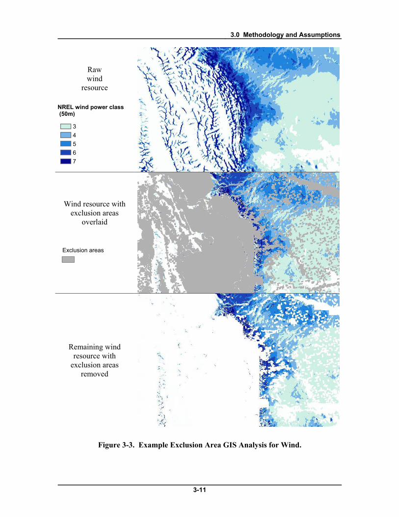
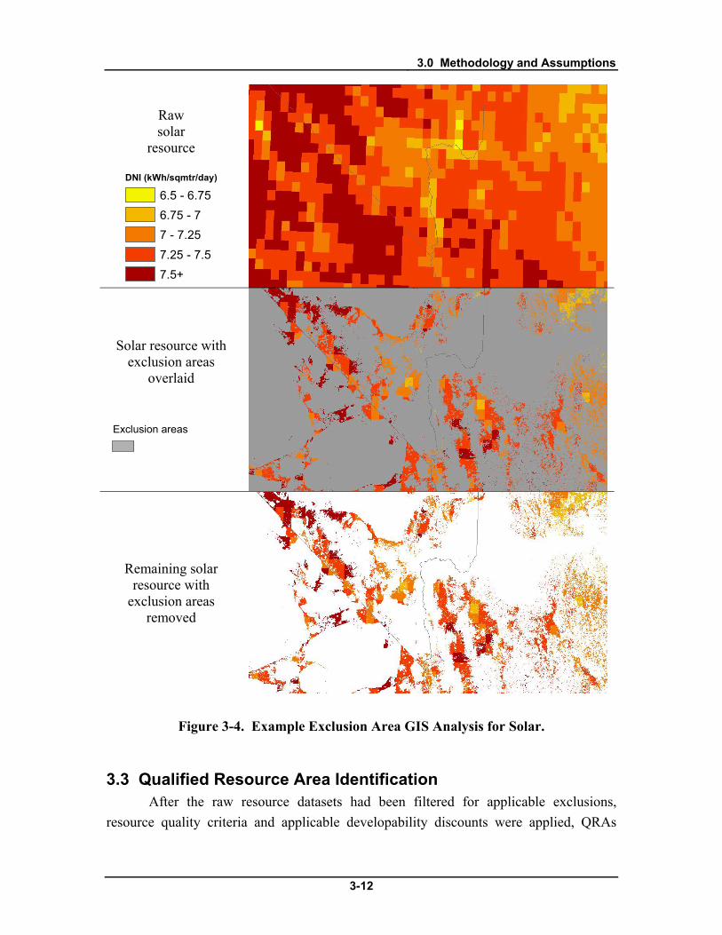
3.2.4 Removing Exclusion Areas Once technical and environmental exclusion areas and resource quality criteria
were defined, exclusion areas were removed from the appropriate renewable energy resource datasets using GIS software. The resulting datasets quantified only the resources that were not located in exclusion areas, and which met the applicable resource quality criteria. These made up the developable renewable energy resources that were quantified in the QRA analysis.
Figure 3-3 and Figure 3-4 are examples of this GIS exclusion analysis. These figures show the process of eliminating exclusion areas from raw wind potential in central Montana and the process of eliminating exclusion areas from raw solar thermal potential on the Nevada, Arizona and California borders.
3.0 Methodology and Assumptions
3-11
Raw wind
resource
Wind resource with
exclusion areas overlaid
Remaining wind resource with
exclusion areas removed
Figure 3-3. Example Exclusion Area GIS Analysis for Wind.
4 3
5 6 7
NREL wind power class (50m)
Exclusion areas
3.0 Methodology and Assumptions
3-12
Raw solar
resource
DNI (kWh/sqmtr/day)
6.5 - 6.75
6.75 - 7
7 - 7.25
7.25 - 7.5
7.5+
Solar resource with exclusion areas
overlaid
Remaining solar resource with
exclusion areas removed
Figure 3-4. Example Exclusion Area GIS Analysis for Solar.
3.3 Qualified Resource Area Identification After the raw resource datasets had been filtered for applicable exclusions,
resource quality criteria and applicable developability discounts were applied, QRAs
Exclusion areas

3.0 Methodology and Assumptions
3-13
were identified using GIS software based on minimum and maximum QRA size criteria developed by the ZITA working group. This was a dynamic process. New exclusion area data were received at various points during the study and working groups discussed and tested various approaches to resource discounts. Additionally, resources were added to the analysis. As a result, QRAs were re-drawn multiple times over the course of the study.
At the request of the WREZ Steering Committee, the QRAs were eventually converted into “hubs,” which are graphical representations of the magnitude of all WREZ resources quantified in each QRA. Hubs were sized in proportion to the total amount of electricity (in terawatt-hours) that the qualifying resources in the QRA are likely to produce during a typical year. Each state and province participating in the WREZ initiative was given the chance to review and modify its maps of hubs in advance of the hub map’s publication and inclusion in the WGA’s WREZ Phase 1 report.16
3.3.1 Grid Square Analysis
The hub map is shown in Chapter 5.0.
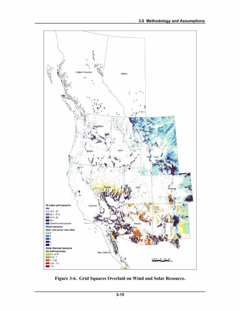
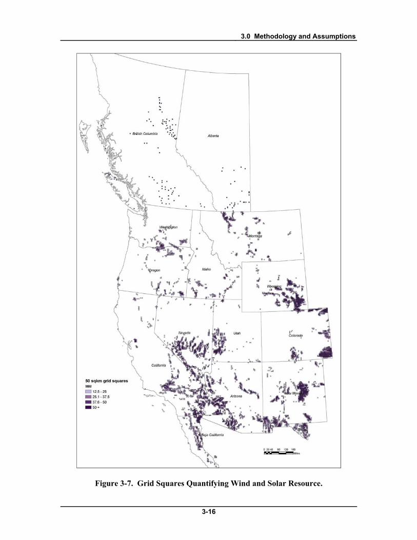
In order to compare resources across large areas and select QRAs, a grid of 50 square kilometer squares (approximately 7 km on a side) was overlaid on the entire WREZ study area. Using the resource datasets filtered for applicable exclusions, the amount of screened renewable energy resource potential within each grid square was quantified. Grid squares were shaded based on the total MW of resource inside them. This enabled Black & Veatch to compare areas across the WREZ study area based on the density of renewable energy resources.
The following three figures show how the GIS grid square analysis was carried out. The wind and solar resource potential across the entire study area is quantified in each grid square and the squares are shaded to show varying density of resource potential across the area.
16 Western Governor’s Association, Western Renewable Energy Zones - Phase 1 Report, Available: http://www.westgov.org/wga/publicat/WREZ09.pdf, June 2009

3.0 Methodology and Assumptions
3-14
Figure 3-5. Wind and Solar Resources Screened for Exclusions.
3.0 Methodology and Assumptions
3-15
Figure 3-6. Grid Squares Overlaid on Wind and Solar Resource.
3.0 Methodology and Assumptions
3-16
Figure 3-7. Grid Squares Quantifying Wind and Solar Resource.

3.0 Methodology and Assumptions
3-17
3.3.2 QRA Selection QRAs were defined as blocks of grid squares that met the resource and size
criteria developed by the ZITA working group. Criteria were applied and visualized using GIS software.
QRA-Defining Resources The ZITA work group anticipated that while certain resources would have enough
potential in an area to justify the creation of a QRA on their own merits, others would be of interstate interest only if they were part of a QRA based on the merits of other stronger resources. QRA-defining resources were called “primary resources” and resources that would be quantified in a QRA if it was created for other resources were called “secondary resources.” • Primary resources are resources with high quality resource potential across an area
that is small enough to qualify as a QRA to potentially justify the construction of a 500 kV transmission line. These resources can define a QRA’s area.
• Secondary resources are resources that generally do not have enough resource potential across an area small enough to qualify as a QRA to justify a 500 kV transmission line. These resources were quantified only when they fell inside the boundaries of a QRA created for primary resources, to the extent they were not excluded under E&L criteria.
Minimum QRA Size The minimum QRA size was based on electricity generating potential. A
minimum QRA size of 1,500 MW was used because it is the approximate minimum capacity required to justify the construction of a 500 kV transmission line.
An exception to this criterion was made for geothermal resources. QRAs made up of only geothermal resources could be as small as 500 MW. Geothermal has on average two to three times the capacity factor of variable wind and solar resources, which means it can produce two to three times as much energy over the course of a year as wind or solar. As a result, it was determined that a geothermal resource could justify a QRA with 500 MW of potential.
An exception was also made for British Columbia and Alberta. Resources in these provinces were identified based on project development activity and site-level resource assessments, rather than large-scale resource maps. There is higher certainty that these resources will be developed than those identified in the United States. To account for this difference in likelihood of development of resources and to ensure QRAs
3.0 Methodology and Assumptions
3-18
in the United States and Canada were comparable, this refinement in the MW thresholds was made.
Maximum QRA Size The maximum QRA size was based on geographical extent, rather than generating
capacity. A maximum QRA size of approximately 100 miles around from a QRA’s center was used. A larger area would increase the estimated levelized cost of a hypothetical collector system to more than $10/MWh, which the ZITA working group concluded would be the maximum cost that a project developer would be willing to incur for grid interconnection.
In order to determine this maximum, the costs of different collector line distances were calculated for wind and solar assuming a standard plant capacity and capacity factor for each technology, a single per MW-mile cost for a 115 kV collector line, and a generation project life of 20 years. Using these assumptions, the distance from a project to its collector substation could be as much as 100 miles before the cost of the collector line exceeded $10/MWh.
QRA Selection Process QRAs were selected using a GIS map of the shaded grid squares and the GTM
working group’s transmission corridors. In many cases, isolated contiguous clusters of resource large enough to be QRAs were easily identified. In other cases, contiguous clusters of resource needed to be broken into multiple parts or multiple smaller clusters needed to be combined to form a QRA exceeding the minimum MW size threshold.
When a contiguous cluster of grid squares covered too large an area to be a single QRA, it was divided generally based on its position in relation to transmission lines. A point was selected on the nearest transmission line and a radius of 100 miles from that point was measured. All of the grid squares that fell within that radius were considered the extent of that QRA. The remaining grid squares in the large contiguous cluster of resource was considered one or more QRAs. When a contiguous cluster of grid squares larger than 200 miles across intersected multiple transmission lines, multiple anchor points were used to break up the cluster. In a small number of cases, a very dense and very large QRA was partitioned into smaller areas that still greatly exceeded the minimum threshold of 1,500 MW.
In several cases, there were not enough grid squares in a single contiguous block to meet the minimum size threshold. In these cases several separate clusters were aggregated to meet the minimum MW size threshold while still staying within the 200 mile size constraint.

3.0 Methodology and Assumptions
3-19
Once QRAs were identified based on primary resources, the secondary resource potential was quantified when it fell inside QRA boundaries. In a few cases, when a QRA’s primary resource potential was not great enough to meet the minimum size criteria, it was supplemented with secondary resource potential.
Creating “Hubs” Once QRAs were quantified, they were visualized as “hubs” for the WGA WREZ
Phase 1 report, as mentioned above. The hubs were created by creating a point at the centroid of the collection of grid squares that made up each QRA. These points were then sized-ramped on the map based on the estimated total TWh/yr energy production of each QRA. States and provinces were then given the opportunity to move the location or eliminate hubs for the final hub map. This hub map is shown in Chapter 5.0.
3.4 Economic Analysis of QRAs Once QRAs were identified, a cost of generation for each resource within each
QRA was evaluated, which included the cost of generation tie lines required to deliver energy from theoretical plants to the transmission system.
3.4.1 Generation Cost The cost of generation (including the generation tie line) was calculated as a
levelized cost of generating power over the life of the resource. The cost of generation was calculated on a $/MWh basis, allowing the resource in question to be compared with disparate resources types with different costs and operating over different time periods. It was calculated using a simple financial model that considers the project from the point of view of a developer, including the developer’s direct costs, charges and incentives, as well as an expected rate of return on the equity. Specifically, it considered:
• Operations and maintenance costs • Fuel costs (as appropriate) • Cost of equity investment in capital • Cost of financing capital • Taxes, including investment and production credits
Other costs, such as insurance, property taxes, development fees, interest during
construction, and debt service reserve funds are included within these major categories. Black & Veatch strived to make the model as simple as possible while still maintaining an appropriate level of accuracy for comparing the relative generation cost of different

3.0 Methodology and Assumptions
3-20
projects employing different renewable energy technologies. The simplifying assumptions allowed the model to serve its analytical purpose and still be streamlined enough to evaluate hundreds of projects. Because of the simplifications, the model was not intended to simulate the exact financial performance of any one project. Use of the model in this way would be inappropriate.
Line items and calculations in the Cost of Generation Calculator are outlined below. A screenshot of the calculator is included in Figure 3-8.
• NPV for Equity Return: A cost of equity is assumed as part of the financial
assumptions. This number is treated as a hurdle which the project must reach. The project must generate sufficient income from power sales to obtain this return on equity. The Net Present Value (NPV) for Equity Return discounts all cash flows associated with the project by this prescribed return to generate a present value. If this metric is zero, the project is returning exactly the prescribed amount to equity investors. Higher values mean that the project generates too much money, and lower values mean that it does not generate enough.
• Levelized Cost of Generation: The actual cost of generation used in the model escalates over time. The levelized cost of generation is the constant cost (no escalation) that produces the same net present value as the actual modeled costs of generation over the life of the project. This single metric is the main output of the model.
• Annual Generation: The annual generation for the project is calculated based on an 8,760 hour year, the project capacity and the assumed capacity factor.
• Cost of Generation: The Year one cost of generation is chosen such that the NPV for Equity Return is zero. Costs of generation in later years are escalated by the assumed value.
• Fixed Operations and Maintenance: Fixed O & M is calculated from the assumed dollars per kilowatt of capacity per year, the project capacity and the assumed escalation value.
• Variable Operations and Maintenance: Variable O & M is calculated from the assumed dollars per megawatt-hour, the annual generation and the assumed escalation value.
• Fuel Cost: Annual generation, net plant heat rate, fuel cost and annual escalation of fuel cost determine the annual fuel cost for the project.
• Debt Service: Mortgage-style principal and interest payments are calculated for the proportion of the project that is assumed to be financed, the debt rate and the term of the financing.
3.0 Methodology and Assumptions
3-21
• Tax Depreciation: Depreciation of project assets are calculated for tax purposes. These numbers are based on the Modified Accelerated Cost Recovery System (MACRS) depreciation schedules. Multiple depreciation schedules (5, 7, 15 or 20 years) can be applied to a single project.
• Production Tax Credit (PTC): The production tax credit is modeled using three parameters: the dollars per megawatt-hour credit, the annual escalation of the credit, and the duration of PTC availability in years.
• Investment Tax Credit (ITC): ITC eligible projects are credited the prescribed percent of their capital costs in year one.
• Taxes: Projects pay an all-in combined tax rate on their taxable income (operating revenue less operating expenses and depreciation) and are credited for applicable tax credits (PTC and ITC).
• Total: These are the cash flows associated with the project, including the equity investment portion of the overall capital costs (accounted for as a single value in year zero).

3.0 Methodology and Assumptions
3-22
Figure 3-8. Example Generation Cost Calculation for a Wind Project.
3.0 Methodology and Assumptions
3-23
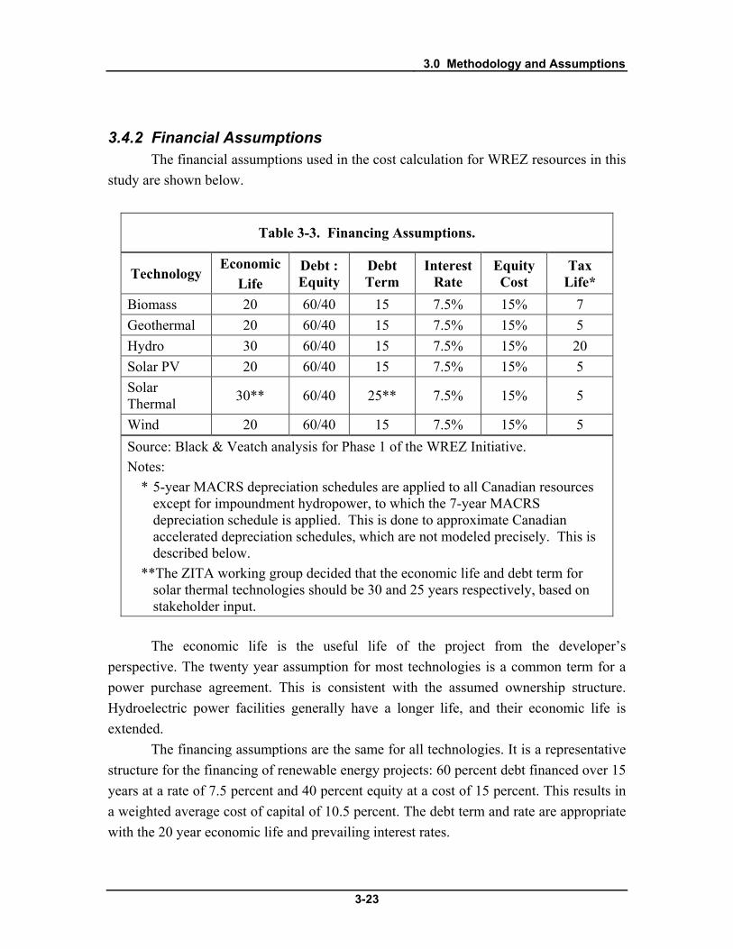
3.4.2 Financial Assumptions The financial assumptions used in the cost calculation for WREZ resources in this
study are shown below.
Table 3-3. Financing Assumptions.
Technology Economic
Life Debt : Equity
Debt Term
Interest Rate
Equity Cost
Tax Life*
Biomass 20 60/40 15 7.5% 15% 7 Geothermal 20 60/40 15 7.5% 15% 5 Hydro 30 60/40 15 7.5% 15% 20 Solar PV 20 60/40 15 7.5% 15% 5 Solar Thermal 30** 60/40 25** 7.5% 15% 5
Wind 20 60/40 15 7.5% 15% 5 Source: Black & Veatch analysis for Phase 1 of the WREZ Initiative. Notes:
* 5-year MACRS depreciation schedules are applied to all Canadian resources except for impoundment hydropower, to which the 7-year MACRS depreciation schedule is applied. This is done to approximate Canadian accelerated depreciation schedules, which are not modeled precisely. This is described below.
**The ZITA working group decided that the economic life and debt term for solar thermal technologies should be 30 and 25 years respectively, based on stakeholder input. The economic life is the useful life of the project from the developer’s
perspective. The twenty year assumption for most technologies is a common term for a power purchase agreement. This is consistent with the assumed ownership structure. Hydroelectric power facilities generally have a longer life, and their economic life is extended.
The financing assumptions are the same for all technologies. It is a representative structure for the financing of renewable energy projects: 60 percent debt financed over 15 years at a rate of 7.5 percent and 40 percent equity at a cost of 15 percent. This results in a weighted average cost of capital of 10.5 percent. The debt term and rate are appropriate with the 20 year economic life and prevailing interest rates.

3.0 Methodology and Assumptions
3-24
The cost of equity is an approximation of the return on investment that a renewable energy project investor would require, taking into account the rate of return that an investor could receive on a comparable investment. It is understood that the cost of equity varies between technologies and projects based on the perceived risk and innumerable other factors. In the absence of a generally accepted set of assumptions, however, Black & Veatch did not see adequate justification for assuming differences.
The tax life is the depreciation schedule for project assets. Tax incentives permit accelerated depreciation for most renewable projects as described further in the next section.
There are several additional assumptions that are made to support the economic analysis:
• Combined federal and state income tax rate: 40 percent (US/Canada) 28 percent (Mexico)
• Discount rate: 10.5 percent • General inflation: 2.5 percent
3.5 Renewable Energy Financial Incentives A number of financial incentives are available for the installation and operation of
renewable energy technologies. The incentives available to new renewable energy facilities and those that were applied to WREZ resources in the economic analysis are briefly discussed below.
3.5.1 U.S. Federal Government The predominant federal incentive for renewable energy has been offered through
the U.S. tax code in the form of tax deductions, tax credits, or accelerated depreciation. An advantage of this form of incentive is that it is defined in the tax code and is not subject to annual congressional appropriations or other limited budget pools (such as grants and loans). Tax-related incentives include:
• Section 45 Production Tax Credit (PTC) • Section 48 Investment Tax Credit (ITC) • Accelerated depreciation The Section 45 PTC is available to private entities subject to taxation for the
production of electricity from various renewable energy technologies. The income tax credit amounts to 1.5 cents/kWh (subject to annual inflation adjustment and equal to 2.1 cents/kWh in 2009) of electricity generated by wind, solar, geothermal, and closed-loop biomass. The credit is equal to 0.75 cents/kWh (inflation adjusted, equal to 1.0 cents/kWh in 2009) for all other renewable energy technologies. A problem with the

3.0 Methodology and Assumptions
3-25
credit is the ever-present threat of expiration, which promotes boom and bust building patterns. The PTC was recently extended in February 2009 to the end of 2012 for wind and the end of 2013 for all other resources as part of HR 1, the American Recovery and Reinvestment Act (ARRA, or the “Stimulus Bill”).
Major provisions of the Section 45 PTC are presented in Table 3-4.
Table 3-4. Major Production Tax Credit Provisions.
Resource Eligible In-service Dates
Credit Size* Special Considerations
Wind 12/31/93 - 12/31/12 Full None Biomass
Closed-Loop 12/31/92 - 12/31/13 Full Crops grown specifically for energy Closed-Loop Cofiring 12/31/92 - 12/31/13 Full Only specific coal power plants;
based on % of biomass heat input Open-Loop Before 12/31/13 Half Does not include cofiring Livestock Waste Before 12/31/13 Half >150 kW. Poultry Waste 10/22/04 - 12/31/13 Full Incorporated with “livestock waste” with the
American Jobs Creation Act of 2004 Geothermal 12/31/99 - 12/31/13 Full Cannot also take investment tax credit Solar 10/22/04 - 12/31/13 Full Cannot also take investment tax credit;
eligibility expired Dec. 31, 2005 Small Irrigation Hydro 10/22/04 - 12/31/13 Half No dams or impoundments; 150 kW-5 MW Incremental Hydro 10/22/04 - 12/31/13 Half Increased generation from existing sites Landfill Gas 8/8/05 - 12/31/13 Half Cannot also take Sec. 29 tax credit Municipal Solid Waste 10/22/04 - 12/31/13 Half Includes new units added at existing plants Source: Black & Veatch research. Notes:
* All PTCs are inflation-adjusted and equaled $21/MWh (“Full”) or $10/MWh (“Half”) in 2009.
The Section 48 ITC effectively offsets a portion of the initial capital investment in a project. The Energy Policy Act of 2005 modified the ITC to include additional resources and increased the credit amount. While utilities originally were not eligible to receive the ITC, the extension of the ITC passed in 2008 changed this wording to allow utilities to claim the ITC if they have a tax burden. In addition, ARRA expanded the eligibility to a broader range of resources. The ITC provisions are now:
• Solar – Eligible solar equipment includes solar electric and solar thermal systems. The credit amount for solar is 30 percent for projects that come online prior to December 31, 2016; otherwise, it is 10 percent.
• Geothermal – Geothermal includes equipment used to produce, distribute, or use energy derived from a geothermal deposit. The credit amount for geothermal is 30 percent for plants that come online prior to December 31, 2012., but cannot be taken in conjunction with the PTC.
3.0 Methodology and Assumptions
3-26
• Wind – Units must be placed into service by December 31, 2012. • Biomass, LFG, hydro, and anaerobic digestion – Units must be placed into
service by December 31, 2013. One major non-tax related incentive to come from the ARRA is a new renewable
energy grant program. Project owners with a tax burden can receive a grant after the project is placed into service equal to 30 percent of the project’s capital cost. Projects must begin construction by the end of 2010, and must be placed into service by 2012 (wind), 2016 (solar), or 2013 (all other eligible resources). If the grant is utilized, the project cannot apply the benefits of the PTC or ITC. Since this program will largely have an impact similar to that of the 30 percent ITC program, it is not modeled separately in the financial pro forma.
The language of the PTC extension does not allow claiming of both the PTC and the ITC. Project developers must choose one or the other. For capital-intensive solar projects, the ITC is typically more attractive. The ITC also interacts with accelerated depreciation, as discussed further below.
Section 168 of the Internal Revenue Code contains a Modified Accelerated Cost Recovery System (MACRS) through which certain investments can be recovered through accelerated depreciation deductions. There is no expiration date for the program. Under this program, certain power plant equipment may qualify for 5-year, 200 percent (i.e., double) declining-balance depreciation, while other equipment may also receive less favorable depreciation treatment. Renewable energy property that will receive MACRS includes solar (5-year), wind (5-year), geothermal (5-year), qualifying hydropower (5-year) and biomass (7-year). Typically, the majority of the project capital cost, but not all, can be depreciated on an accelerated schedule. However, for biomass, only the boiler portion of the plant receives MACRS (about 60 percent of the project cost). The ARRA included a “bonus depreciation” allowance for most qualified renewable energy facilities that allowed 50% depreciation during the first year of operation provided that the facility commenced operation in 2009.
The accelerated depreciation law also specifies that the depreciable basis is reduced by the value of any cash incentives received by the project, and by half of any federal investment tax credits (e.g., the ITC). This provision has the effect of lowering the depreciable basis to 95 percent for projects that receive the 10 percent ITC and 85 percent for projects that take the 30 percent ITC. The cost of generation for all US resources was modeled assuming they received the 30 percent ITC and the appropriate MACRS depreciation.
3.0 Methodology and Assumptions
3-27
3.5.2 State Financial Incentives All U.S. states within the WREZ study area have incentives for renewable energy
projects. Black & Veatch reviewed the incentives and concluded that none would have a substantive effect on the analysis. Therefore, for the sake of simplicity, the assessment does not include state incentives.
3.5.3 Canadian Incentives The Canadian federal government has two applicable incentive programs for
renewable energy. First, it offers an accelerated depreciation program for renewable energy, the Capital Cost Allowance (CCA) 43.2. This incentive grants geothermal, wind and small hydropower resources a 50 percent declining accelerated depreciation benefit. It grants conventional, large hydropower a 30 percent declining accelerated depreciation benefit. In each case, the depreciation rate is halved for the first year. Black & Veatch determined that the Canadian 50 percent CCA accelerated depreciation schedule and the 30 percent CCA for renewable energy have a similar effect on the net present value of a project as the US MACRS depreciation schedules. As a result, all technologies that qualify for the 50 percent CCA were modeled with the 5-year MACRS depreciation schedule, and all technologies that qualify for the 30 percent CCA were modeled with the 7-year MACRS depreciation schedule.
The federal government also offers the EcoENERGY incentive for Renewable Power program. It was, however, determined by the WREZ ZITA working group that the EcoENERGY incentive would soon expire and was not applicable to this analysis. The only incentives that were applied to Canadian renewable energy resources were the MACRS 5-year depreciation schedules that mimic the CCA schedules.
3.5.4 Mexican Incentives Mexico has several incentives for renewable energy development including 95
percent one-year accelerated depreciation, potential for Kyoto Protocol Clean Development Mechanism carbon credits at rates not available to U.S. projects, favorable export credit treatment from organizations such as the U.S. Export Import Bank, and other incentives.17
However, the 95 percent 1 year depreciation was mimicked using the models for the US incentives. It was determined that this could be mimicked by granting Mexican projects zero depreciation but providing them a tax credit in the first year equal to 95 percent of their tax liability.
The potential for Clean Development Mechanism credits were not modeled directly, because it was determined to be outside the scope of this project.
3.0 Methodology and Assumptions
3-28
3.5.5 Future Term and Nature of Incentives The future of financial incentives is a source of uncertainly in the analysis. The
extension of both the PTC and ITC as part of the ARRA now has the PTC expiring at the end of 2012-2013 and the 30 percent ITC/grant program expiring at the end of 2012, 2013, or 2016, depending on the technology. These incentives have a substantial impact on the cost of generation from renewables. It was accepted by stakeholders in the WREZ ZITA working group process that all incentives will, in general and in some form, be available to renewable energy projects over the term of this study. The decision of the ZITA working group was to assume that existing financial incentives extend in their current form throughout the study period.
3.6 Non-REZ Resources It is important to quantify not only the resources that meet the specific criteria
developed to identify QRAs, but also other resources that might help achieve the broader goals of the WREZ initiative. The overarching goal of the WREZ initiative is “to improve the balance and overall adequacy of renewable and traditional energy resources in a manner that will strengthen economic growth, promote energy price stability, mitigate environmental impact, maximize reliability and result in an abundance of diversified resource supplies.”18
• May not require extra-high voltage transmission in order to be economically viable;
Pursuant to that goal, this report quantifies renewable energy resources that may be significant and commercially viable even though they may lie outside of a QRA. The economics of these resources are not assessed and they are not included in the supply curve analysis. These resources are referred to as non-REZ resources. Non-REZ resources
• Primarily serve load in the same locality, state, province or utility service area; and
• Do not need to be concentrated in one place to be developed.
The specific qualities and types of non-REZ resources are described for each resource type in Chapter 4.0. Non-REZ resources are also quantified and summarized in this chapter as well as in Chapter 5.0.
17 Personal communication from James Walker, Asociados Panamericanos, April 23, 2008 18 Western Governor’s Association, Western Renewable Energy Zones - Phase 1 Report, Available: http://www.westgov.org/wga/publicat/WREZ09.pdf, June 2009

4.0 Resource Characterization
4-1
4.0 Resource Characterization
This section describes the WREZ resources resource assessment, QRA identification and the non-REZ resource assessment process for biomass, geothermal, hydropower, solar, and wind resources in WREZ.
4.1 Biomass This section details Black & Veatch’s approach to the identification of biomass
direct fired projects for the purposes of WREZ analysis. WREZ biomass was considered a secondary resource and was quantified when it could theoretically be located inside of QRA boundaries created for primary resources (geothermal, some hydro, solar, wind). Some biomass resources have been characterized in almost every QRA. This section discusses the methodology used to characterize the resources suitable for biomass direct firing technology. The general approach was to identify potential biomass resource potential based on the availability of different feedstocks.
4.1.1 Resource Assessment Methodology Biomass resources are unique in the WREZ analysis: while the resource is
generally distributed over a large area, the biomass fuel can be transported to the point of best use. This allows for a high degree of siting flexibility. For example, biomass projects can be sited near existing transmission lines with available transfer capacity. Projects can also be sited to avoid environmentally sensitive areas. At about 1 acre per MW, the physical footprint of biomass plants is relatively low. For these reasons, the resource assessment methodology for biomass focused on the amount of biomass fuel available to a particular QRA and did not identify specific locations of theoretical projects.
Slightly different resource assessment methodologies were used in the US and Canada because the data available were different. No biomass resources were identified in Baja, due to lack of data.
US For US QRAs, county-level biomass feedstock data from NREL, the Western
Governor’s Association (WGA), the California Biomass Collaborative (CBC) and the Washington State Department of Ecology (WA ECY) were used as the basis for identifying the total amount of biomass that could be used for fuel for power generation

4.0 Resource Characterization
4-2
across the western US.19,20,21,22
The WREZ study set out to include a number of specific biomass resources that were thought to be newly available and potentially not captured in large-scale resource assessments. These included mountain pine beetle kill wood, vineyard and orchard residues, piñon juniper removals and green waste sites located in forest communities on US Forest Service land. It was determined that the WGA dataset included pine beetle kill wood and piñon juniper removals, as well as resources available from USFS green waste sites in the US. Reliable pine beetle kill data were not available for British Columbia and Alberta although significant time and effort was put into developing a sound methodology to assess these resources. Finally, it was determined from communications with the British Columbia Forest Service that it could not be reliably estimated given the data available and scope of this project.
The feedstock types assessed, which were chosen by the WREZ ZITA working group, included agricultural residues (orchard/vineyard, field/seed crop, vegetable crop, and food/fiber), forest residues (forest thinnings and slash, and mill residues), and urban wood waste. Forest and agricultural data used in this study came from the WGA report, orchard and vineyard residue data came from the CBC and WA ECY reports and urban wood waste data came from the NREL report.
23
Technically Available Potential
Data on vineyard and orchard residues was collected for Washington and California, where these resources were thought to have the greatest impact.
After discussion with biomass stakeholders, Black & Veatch determined that not all theoretically available biomass feedstock capacity would be available for power generation. It was assumed that one-third of the theoretical feedstock capacity quantified in the NREL, CBC and WA ECY biomass data would be available for power generation. The remainder was assumed to be unavailable or used in competing markets such as for mulch, biofuels, and other purposes.
The WGA report quantified the amount of biomass available at various costs and the amount of resources available at a particular price point was used as the basis for
19 Milbrandt, Anelia, A Geographic Perspective on the Current Biomass Resource Availability in the United States," 2005. NREL Technical Report NREL/TP-560-39181. 20 Western Governor’s Association Biomass Task Force, Strategic Assessment of Bioenergy Development in the West, Available: http://westgov.org/wga/initiatives/transfuels/index.html, 2008 21 California Energy Commission, An Assessment of Biomass Resources in California, PIER Collaborative Report 500-01-016, California Biomass Collaborative, 2006 22 Fuchs, Mark and Frear, Craig et al, Biomass Inventory and Bioenergy Assessment: An Evaluation of Organic Material Resources for Bioenergy Production in Washington State, Washington Department of Ecology, Available: http://www.ecy.wa.gov/biblio/0507047.html, 2005 23 Personal communication with Adrian Walton, Landscape Ecologist at the BC Forest Service, April, 2009.

4.0 Resource Characterization
4-3
identifying the amount of biomass available for power generation. Instead of discounting the total resource potential in this dataset, it was assumed that only biomass available at or below $80 per ton would be economically viable for power production. That constraint was assumed to reduce the gross potential to the realistically available potential in a way that was comparable to the two thirds discount applied to the other datasets.
The resulting resource potentials from all the datasets were assumed to be the amount of “technically available” biomass in the study area. The technically available biomass of each feedstock category by county was converted to a MW potential using the heating value for each fuel identified in the CBC study, a heat rate of 13,650 BTU/kWh, and an 85 percent capacity factor. This method defined the capacity (by county) across the western United States.
QRA-Level Assessment The technically available capacity contained in each county located in and near
each QRA was assigned to that QRA using GIS software. A 50-mile buffer was created around QRA boundaries in GIS. The distance that would be required to transport the biomass inside the QRA plus 50 miles was assumed to be the maximum distance that biomass resources could be hauled to a power plant before transportation costs would make collecting the feedstock uneconomic. These buffers were intersected with the county-level biomass data, producing a table indicating which QRA buffers overlapped which counties. In many cases, a single county was overlapped by multiple QRA buffers. Using this table and the visualization of the 50 mile buffers over the counties in GIS, the automatic matching of counties to QRAs was refined using the following rules:
• Counties were assigned to QRAs when they appeared to fall entirely or mostly inside of a QRA's buffer.
• When multiple QRA buffers overlapped a single county, that county was assigned to the QRA whose buffer overlapped the majority of its area.
• If multiple QRAs overlapped the majority of one county, the QRA with the greatest overlap was assigned that county. If multiple QRAs had buffers that overlapped all or most of a county the QRA located within the same state as that county was always assigned that county.
• In cases where two QRA buffers overlapped all or equal amounts of that county in the same state, the QRA that had fewer counties assigned to it was assigned this county.
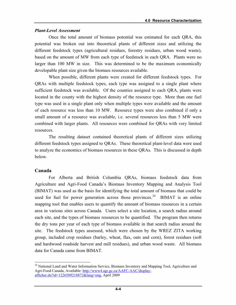
4.0 Resource Characterization
4-4
Plant-Level Assessment Once the total amount of biomass potential was estimated for each QRA, this
potential was broken out into theoretical plants of different sizes and utilizing the different feedstock types (agricultural residues, forestry residues, urban wood waste), based on the amount of MW from each type of feedstock in each QRA. Plants were no larger than 100 MW in size. This was determined to be the maximum economically developable plant size given the biomass resources available.
When possible, different plants were created for different feedstock types. For QRAs with multiple feedstock types, each type was assigned to a single plant where sufficient feedstock was available. Of the counties assigned to each QRA, plants were located in the county with the highest density of the resource type. More than one fuel type was used in a single plant only when multiple types were available and the amount of each resource was less than 10 MW. Resource types were also combined if only a small amount of a resource was available, i.e. several resources less than 5 MW were combined with larger plants. All resources were combined for QRAs with very limited resources.
The resulting dataset contained theoretical plants of different sizes utilizing different feedstock types assigned to QRAs. These theoretical plant-level data were used to analyze the economics of biomass resources in these QRAs. This is discussed in depth below.
Canada For Alberta and British Columbia QRAs, biomass feedstock data from
Agriculture and Agri-Food Canada’s Biomass Inventory Mapping and Analysis Tool (BIMAT) was used as the basis for identifying the total amount of biomass that could be used for fuel for power generation across those provinces.24
24 National Land and Water Information Service, Biomass Inventory and Mapping Tool, Agriculture and Agri-Food Canada, Available:
BIMAT is an online mapping tool that enables users to quantify the amount of biomass resources in a certain area in various sites across Canada. Users select a site location, a search radius around each site, and the types of biomass resources to be quantified. The program then returns the dry tons per year of each type of biomass available in that search radius around the site. The feedstock types assessed, which were chosen by the WREZ ZITA working group, included crop residues (barley, wheat, flax, oats and corn), forest residues (soft and hardwood roadside harvest and mill residues), and urban wood waste. All biomass data for Canada came from BIMAT.
http://www4.agr.gc.ca/AAFC-AAC/display-afficher.do?id=1226509218872&lang=eng, April 2009

4.0 Resource Characterization
4-5
Technically Available Potential After discussion with stakeholders, it was concluded that one-third of the
theoretical feedstock capacity quantified in the BIMAT data would be available for power generation. The remainder was assumed to be unavailable or used in competing markets such as for mulch, biofuels, and other purposes.
QRA-Level Assessment As mentioned above, the distance that would be required to transport the biomass inside the QRA plus 50 miles was assumed to be the maximum distance that biomass resources could be hauled to a power plant before transportation costs would make collecting the feedstock uneconomic. The Canadian biomass assessment sought to quantify biomass resources within a radius of 50 miles around the edge of each QRA. Since users are only allowed to choose a central location around which to collect biomass resources in the BIMAT tool, Black & Veatch estimated the size of the circle required based on the size of the Canadian QRAs. These radii were then used in the BIMAT tool to quantify the amount of resources inside of each. These resources were then attributed to that QRA.
Plant-Level Assessment The same methodology was used to break biomass resources into theoretical
plants in Canada as was used in the US. The resulting dataset contained theoretical plants of different sizes utilizing different feedstock types assigned to QRAs. These theoretical plant-level data were used to analyze the economics of biomass resources in these QRAs. This is discussed in greater depth below.
Biomass Resource Map A map of all biomass resources assessed in the US for WREZ is shown below in
Figure 4-1. This map shows theoretical biomass generating potential in MW at the county level. Generating potential was calculated based on county level estimates of the amounts of different types of biomass resources available for power production annually. Estimates of the amount of feedstock available were discounted to reflect technical potential and converted to generating potential using the US biomass resource assessment assumptions described above.
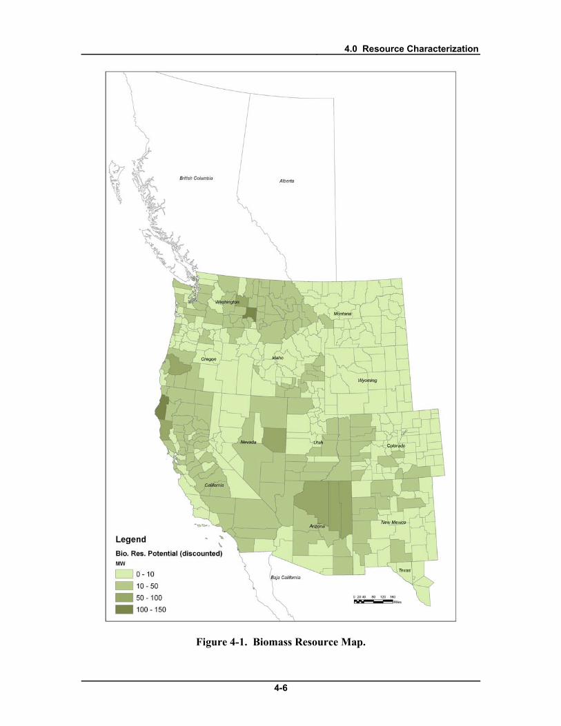
4.0 Resource Characterization
4-6
Figure 4-1. Biomass Resource Map.
4.0 Resource Characterization
4-7
4.1.2 Resource Supply Curve Characteristics Combustion of biomass fuel was assumed to take place in a stoker or fluidized
bed steam generator with a standard steam power cycle. Assumed emissions control equipment included selective non-catalytic reduction (SNCR) for NOx control and a baghouse/electrostatic precipitator for particulate control. This combination represents conventional technology which has been proven over many years of operation. The assumptions that went into the biomass supply curve economic analysis for this type of plant are detailed below.
Capital Cost Capital cost for the projects considered (3 to 100 MW) ranged from around
$3,400 to around $6,000/kW, based on a review of recent cost estimates performed by Black & Veatch. The capital cost is inclusive of generation tie-line and interconnection costs. This range is wider than the range anticipated by the WREZ ZITA working group due to the fact that the analysis identified some theoretical plants that are smaller than the smallest plants the working group anticipated.
Operations & Maintenance Operations and maintenance (O&M) costs ranged from around $24/MWh to
$52/MWh. This range is somewhat wider than the range anticipated by the WREZ ZITA working group due to the fact that O&M costs tends to increase as plant size decreases, and the WREZ analysis identified some theoretical plants that are smaller than the ZITA group anticipated.
Fuel Cost Estimates of the cost of different biomass fuel feedstocks were developed from
data supplied by the Green Power Institute, updated to 2009 costs, and adapted for the resources identified in the CBC report. Costs for each resource can be found in Table 4-1. Transportation costs were calculated assuming that fuel would not be collected further than 100 miles from the center of the county in which the plant was located. The assumed collection distance was the radius around this theoretical plant location containing 50 percent of the total fuel, assuming the fuel was evenly distributed across the circle around the plant.

4.0 Resource Characterization
4-8
Table 4-1. Biomass Fuel Cost (Undelivered).
Resource Energy Content (BTU/bdt)
Collection Cost (Undelivered), $/bdt
Agricultural Residues 7,790 30 Forest Thinnings/Slash 8,500 41 Urban Wood Waste 7,179 20 Mill Residues 8,597 29
Heat Rate The heat rate varied based on the moisture content of the fuel, with a low of
14,000 BTU/kWh used for urban wood waste (12 percent moisture) to 15,780 BTU/kWh for forest residues (40 percent moisture). These fell within the range expected by the WREZ ZITA working group.
Production Profile A capacity factor of 85 percent was applied to all projects. The generation profile
was assumed to be flat. This assumption was developed by the WREZ ZITA working group.
4.1.3 Results The WREZ biomass analysis identified over 3,700 MW of potential biomass
capacity and over 27 terawatt-hours (TWh) of theoretical annual generation in QRAs across the study area. All states and provinces have some biomass potential, except for Baja. Alberta, British Columbia, Oregon and Idaho have the greatest WREZ biomass resources. Arizona, Nevada and New Mexico also have significant biomass resources, due to the potential availability of piñon-juniper trees, which have expanded beyond their historic range and may provide significant biomass resources in the Southwestern US.25
Economic Analysis
Data on biomass for Baja were not available.
The levelized cost of energy of biomass resources across the WREZ study area ranged from $103/MWh to $165/MWh. The high end of this range is higher than expected by the largely because smaller plants generally produce more expensive energy
25 Western Governor’s Association Biomass Task Force, Strategic Assessment of Bioenergy Development in the West, Available: http://westgov.org/wga/initiatives/transfuels/index.html, 2008

4.0 Resource Characterization
4-9
and some plants are smaller than originally anticipated by the WREZ ZITA working group. Table 4-2 summarizes the biomass performance and economic results. Figure 4-2 is a supply curve of biomass resources in QRAs across the WREZ study area.
Table 4-2. Summary of Biomass Performance and Economics Results.
Performance Net Plant Capacity (MW) 3 to 100 Net Plant Heat Rate (HHV, Btu/kWh) 14,000 to 15,780 Capacity Factor (percent) 85 Economics All-In Capital Cost ($/kW) 3,400 to 6,000 Fuel Cost ($/MBtu) 1.40 to 2.40 Variable O&M Cost ($/MWh) 24 to 52 Levelized Cost of Energy ($/MWh) 103 to 165 Source: Black & Veatch analysis for Phase 1 of the WREZ Initiative.
0 5,000 10,000 15,000 20,000 25,000 30,0000
25
50
75
100
125
150
175
200
225
250
Generation, GWh
Gen
erat
ion
Cost
, $/M
Wh
Wind Biomass Solar Geothermal Hydro
Figure 4-2. WREZ Biomass Supply Curve.
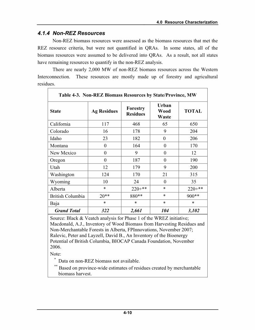
4.0 Resource Characterization
4-10
4.1.4 Non-REZ Resources Non-REZ biomass resources were assessed as the biomass resources that met the
REZ resource criteria, but were not quantified in QRAs. In some states, all of the biomass resources were assumed to be delivered into QRAs. As a result, not all states have remaining resources to quantify in the non-REZ analysis.
There are nearly 2,000 MW of non-REZ biomass resources across the Western Interconnection. These resources are mostly made up of forestry and agricultural residues.
Table 4-3. Non-REZ Biomass Resources by State/Province, MW
State Ag Residues Forestry Residues
Urban Wood Waste
TOTAL
California 117 468 65 650 Colorado 16 178 9 204 Idaho 23 182 0 206 Montana 0 164 0 170 New Mexico 0 9 0 12 Oregon 0 187 0 190 Utah 12 179 9 200 Washington 124 170 21 315 Wyoming 10 24 0 35 Alberta * 220+** * 220+** British Columbia 20** 880** * 900** Baja * * * *
Grand Total 322 2,661 104 3,102 Source: Black & Veatch analysis for Phase 1 of the WREZ initiative; Macdonald, A.J., Inventory of Wood Biomass from Harvesting Residues and Non-Merchantable Forests in Alberta, FPInnovations, November 2007; Ralevic, Peter and Layzell, David B., An Inventory of the Bioenergy Potential of British Columbia, BIOCAP Canada Foundation, November 2006. Note:
* Data on non-REZ biomass not available. ** Based on province-wide estimates of residues created by merchantable
biomass harvest.

4.0 Resource Characterization
4-11
4.1.5 Data Sources • California Energy Commission, An Assessment of Biomass Resources in
California, PIER Collaborative Report 500-01-016, California Biomass Collaborative, 2006
• Fuchs, Mark and Frear, Craig et al, Biomass Inventory and Bioenergy Assessment: An Evaluation of Organic Material Resources for Bioenergy Production in Washington State, Washington Department of Ecology, Available: http://www.ecy.wa.gov/biblio/0507047.html, 2005
• Macdonald, A.J., Inventory of Wood Biomass from Harvesting Residues and Non-Merchantable Forests in Alberta, FPInnovations, November 2007
• Milbrandt, Anelia, A Geographic Perspective on the Current Biomass Resource Availability in the United States," 2005. NREL Technical Report NREL/TP-560-39181.
• National Land and Water Information Service, Biomass Inventory and Mapping Tool, Agriculture and Agri-Food Canada, Available: http://www4.agr.gc.ca/AAFC-AAC/display-afficher.do?id=1226509218872&lang=eng, April 2009
• Peter Ralevic and David B. Layzell, An InventoryWestern Governor’s Association Biomass Task Force, Strategic Assessment of the Bioenergy Potential of British Columbia, BIOCAP Canada Foundation, November 2006
• Western Governor’s Association Biomass Task Force, Strategic Assessment of Bioenergy Development in the West, Available: http://westgov.org/wga/initiatives/transfuels/index.html, 2008

4.0 Resource Characterization
4-12
4.2 Geothermal This section details the approach to the identification of conventional
hydrothermal geothermal resources in QRAs and quantifies the estimated potential of undiscovered resources and Enhanced Geothermal Systems (EGS) potential at the state level based on other studies. Recent studies of resource potential suggest that geothermal resources might have the potential to generate large quantities of renewable energy in the next 10 to 20 years. Based on updated research there may be geothermal energy potential available on the order of a hundred thousand megawatts or more in the Western Interconnection.
Geothermal was considered a primary resource in WREZ when it occurred in large enough quantities and a dense enough dispersion across an area to justify the creation of a QRA. Only known, quantifiable geothermal sources of conventional hydrothermal potential were considered WREZ resources. These were called “discovered conventional geothermal” resources in the WREZ process. Conventional hydrothermal geothermal resources that could not be associated with a specific site, but were thought to exist across a broad area were called “undiscovered, conventional geothermal” resources. These resources were quantified as non-REZ resources at the state/province level and were not included in the supply curve analysis. Non-REZ geothermal resource also included EGS resources, which are discussed in greater depth in the “Non-REZ Resources” section.
4.2.1 Resource Assessment Methodology The geothermal resource assessment for WREZ was completed by GeothermEx,
except for the generation tie-line analysis and production profile analysis, which were completed by Black & Veatch. Input from the private sector, research institutions and government agencies was used to compile a resource map and power production table that shows the varied and significant potential of geothermal resources across the Western Interconnection.
Estimation of geothermal generation potential for specific areas has relied on volumetric estimation of heat in place wherever sufficient information was available to justify this approach. The methodology has been described in detail in a study of California and Nevada geothermal resources for the CEC PIER program (GeothermEx, 2004). In brief, the heat-in-place approach entails estimation of the area, thickness, and average temperature of the geothermal resource. Recovery factors that are based on industry experience are applied to estimate the proportion of heat that can be recovered as electrical energy over an assumed project life of 30 years. Uncertainty in the input

4.0 Resource Characterization
4-13
parameters is handled by a probabilistic approach that yields a range of possible generation values and associated probabilities. The modal value of the probability distribution is considered the “most likely value” of generation potential for the project concerned.
Where there is insufficient resource information to apply the heat-in-place method, estimates of generation potential have been made by analogy to better-known projects in similar geologic environments. If the only public information about a project is that it contains geothermal leases or has been the subject of a geological reconnaissance study, the project size has been estimated at a minimum size of 10 MW (gross). Larger estimates of capacity can be justified even in the absence of published resource data if there is evidence of active geothermal development efforts. For certain large volcanic centers in northern California, Oregon, and southern British Columbia, capacities of 50 MW (gross) have been estimated based on potentially favorable geologic conditions, even in the absence of current development efforts.
Treatment of Undiscovered Geothermal Resources Undiscovered conventional geothermal resources were not identified with this
approach and were not included in the supply curve analysis. For the purposes of near-term transmission planning, it is not possible to accurately and reliably quantify the locations of undiscovered conventional potential. However, estimates have been made of the undiscovered conventional potential at the state and province level by the USGS and Canadian researchers. These estimates are shown in the “Results” section below.
Geothermal Resource Map A geothermal resource map is shown below in Figure 4-3. This map shows the
location of specific potential projects assessed in WREZ as well as areas of “Geothermal Favorability.” Geothermal favorability is a concept used by the USGS that the ZITA working group decided to use as a qualitative measure of the likelihood of undiscovered conventional geothermal and EGS resource potential in an area. Geothermal favorability data are used in the map below to show in general where undiscovered conventional geothermal and EGS resources might be located. These data are from the USGS and the British Columbia Ministry of Energy, Mines and Petroleum.26
26 Personal communications with Jacob DeAngelo at the USGS on November 10, 2008 and Sue Bonnyman at the BC Ministry of Energy, Mines and Petroleum on November 1, 2008; Williams, Colin F., Reed, Marshall J., Mariner, Robert H., DeAngelo, Jacob, Galanis, S. Peter, Jr., 2008, Assessment of Moderate- and High-Temperature Geothermal Resources of the United States: U.S. Geological Survey Fact Sheet 2008-3082,

4.0 Resource Characterization
4-14
Figure 4-3. Geothermal Resource Map.

4.0 Resource Characterization
4-15
4.2.2 Resource Supply Curve Characteristics Characterization of capital and operating costs for geothermal projects was based
as much as possible on industry experience. The costs of drilling and plant equipment have risen markedly in recent years. A comparison of cost estimates from the CEC-PIER report with actual development costs as of 2008 indicates that the CEC-PIER estimates have escalated by about 20 percent.27
Capital Cost
Moreover, a correlation of the CEC-PIER cost estimates with estimated capacities has shown generally higher costs per kW installed for smaller projects. This correlation between cost and project size has been used to estimate the cost of projects not considered by the CEC-PIER study, and the 25 percent escalation factor has been used to express all project costs in 2009 dollars. For British Columbia, a 30 percent escalation factor has been applied to account for development challenges associated with colder climate and rugged topography.
This analysis has yielded capital cost (including generation tie-line cost) estimates ranging from around $4,140 to $13,400/kW (net) installed. This variation was due to a number of factors, but primarily due to plant size. Generation tie-line costs also affected the capital cost of geothermal projects, most dramatically for smaller projects.
Generation tie-line costs were calculated for each geothermal project and added to their capital costs. These costs were calculated for each project based on the distance from the location of each project to the nearest substation at least 115 kV in size. The interconnecting generation tie-lines were assumed to be various voltages, which were chosen and the costs for which were estimated based on Black & Veatch’s experience with transmission facilities of varying sizes. The generation tie-line costs for geothermal plants ranged from less than $20/kW to $1,900/kW for very small projects located in remote areas.
Operations & Maintenance Operating costs have been estimated to range generally from $27 to $42/MWh
(net), with higher costs characterizing the smaller project sizes. The operating cost estimates include site costs, general and administrative overhead, workovers, royalties, and insurance.
27 Broad-based assessments of geothermal potential (such as the USGS assessment of 1979, currently being updated; the CEC-PIER report of 2004; the WGA study of 2006)
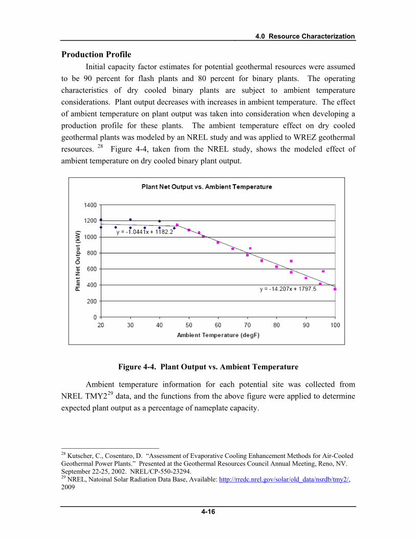
4.0 Resource Characterization
4-16
Production Profile Initial capacity factor estimates for potential geothermal resources were assumed
to be 90 percent for flash plants and 80 percent for binary plants. The operating characteristics of dry cooled binary plants are subject to ambient temperature considerations. Plant output decreases with increases in ambient temperature. The effect of ambient temperature on plant output was taken into consideration when developing a production profile for these plants. The ambient temperature effect on dry cooled geothermal plants was modeled by an NREL study and was applied to WREZ geothermal resources. 28 Figure 4-4 , taken from the NREL study, shows the modeled effect of ambient temperature on dry cooled binary plant output.
Figure 4-4. Plant Output vs. Ambient Temperature
Ambient temperature information for each potential site was collected from NREL TMY229
28 Kutscher, C., Cosentaro, D. “Assessment of Evaporative Cooling Enhancement Methods for Air-Cooled Geothermal Power Plants.” Presented at the Geothermal Resources Council Annual Meeting, Reno, NV. September 22-25, 2002. NREL/CP-550-23294.
data, and the functions from the above figure were applied to determine expected plant output as a percentage of nameplate capacity.
29 NREL, Natoinal Solar Radiation Data Base, Available: http://rredc.nrel.gov/solar/old_data/nsrdb/tmy2/, 2009
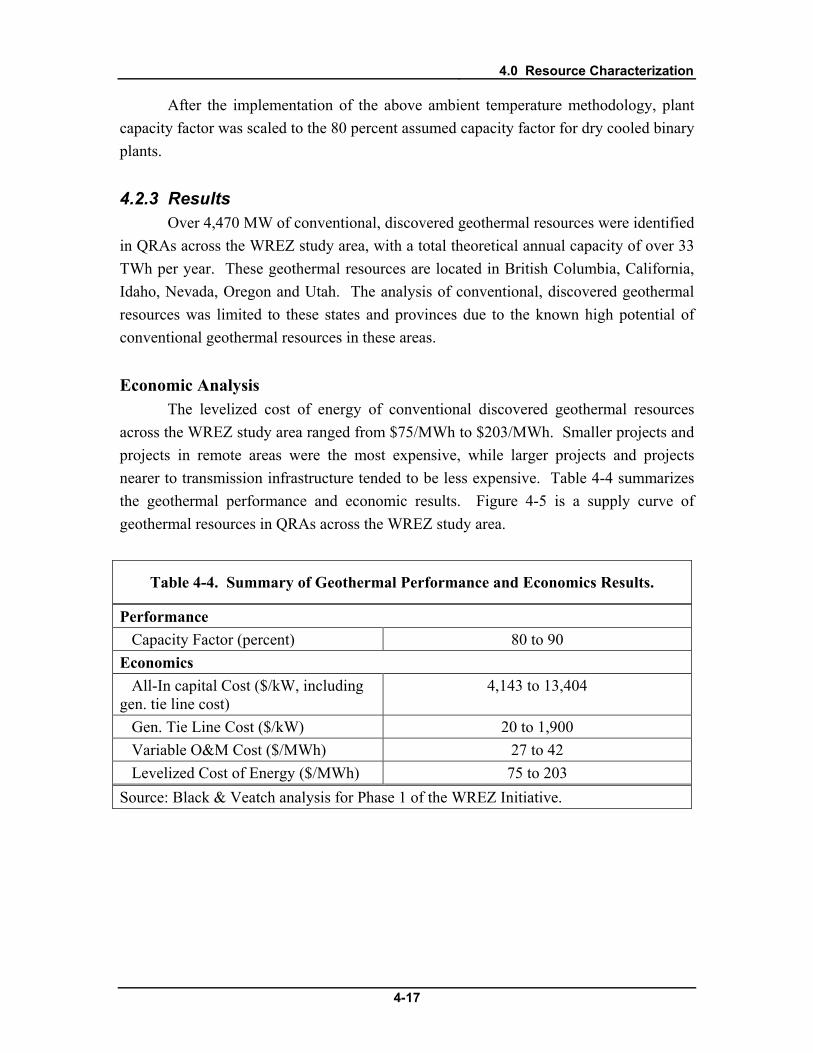
4.0 Resource Characterization
4-17
After the implementation of the above ambient temperature methodology, plant capacity factor was scaled to the 80 percent assumed capacity factor for dry cooled binary plants.
4.2.3 Results Over 4,470 MW of conventional, discovered geothermal resources were identified
in QRAs across the WREZ study area, with a total theoretical annual capacity of over 33 TWh per year. These geothermal resources are located in British Columbia, California, Idaho, Nevada, Oregon and Utah. The analysis of conventional, discovered geothermal resources was limited to these states and provinces due to the known high potential of conventional geothermal resources in these areas.
Economic Analysis The levelized cost of energy of conventional discovered geothermal resources
across the WREZ study area ranged from $75/MWh to $203/MWh. Smaller projects and projects in remote areas were the most expensive, while larger projects and projects nearer to transmission infrastructure tended to be less expensive. Table 4-4 summarizes the geothermal performance and economic results. Figure 4-5 is a supply curve of geothermal resources in QRAs across the WREZ study area.
Table 4-4. Summary of Geothermal Performance and Economics Results.
Performance Capacity Factor (percent) 80 to 90 Economics All-In capital Cost ($/kW, including gen. tie line cost)
4,143 to 13,404
Gen. Tie Line Cost ($/kW) 20 to 1,900 Variable O&M Cost ($/MWh) 27 to 42 Levelized Cost of Energy ($/MWh) 75 to 203 Source: Black & Veatch analysis for Phase 1 of the WREZ Initiative.

4.0 Resource Characterization
4-18
0 5,000 10,000 15,000 20,000 25,000 30,000 35,0000
25
50
75
100
125
150
175
200
225
250
Generation, GWh
Gen
erat
ion
Cost
, $/M
Wh
Wind Biomass Solar Geothermal Hydro
Figure 4-5. WREZ Geothermal Supply Curve.
4.2.4 Non-REZ Resources Non-REZ geothermal resources consisted of undiscovered conventional
geothermal potential as well as EGS potential. Over 31,000 MW of undiscovered, conventional geothermal resources were identified for this study. The general location and magnitude of these resources were estimated based on estimates of the USGS and various research efforts in Canada. These resources could become WREZ resources if the resource potential at specific project sites was quantified. However, site-level data were not available for this assessment so these resources are considered non-REZ resources.
The following describes the approach to EGS resources for WREZ. It was written collaboratively by WREZ stakeholders and is paraphrased below. This excerpt is from the WREZ Zone Identification and Technical Analysis Work Group Resource Criteria Approved by the WREZ Technical Committee at its October 2008 Meeting, available on the Western Governor’s Association website30
:
Resource assessments for identifying QRAs focus on conventional geothermal resources with a high degree of resource certainty. A large potential also exists for Enhanced Geothermal Systems (EGS), known direct-use sites (which are also small power
30 Available: http://westgov.org/wga/initiatives/wrez/zita/resource%20criteria.pdf
4.0 Resource Characterization
4-19
opportunities), and co-production opportunities in oil and gas fields using available data. These opportunities and future potential are regarded here as non-REZ resources, as their economic viability do not depend on the existence of a QRA.
Significant utility-scale EGS development may be 10 years or more from widespread commercial deployment, but the recent infusion of interest and investment will lead to near term development and its pace cannot be accurately predicted at this point in time. Its eventual pace of development may be determined by how fast cost-reductions follow from added experience in the development and operational aspects of EGS projects. Estimates by the Massachusetts Institute of Technology of near-term development of EGS sites, however, show economic potential within the range of other advanced technologies, ranging from 10 cents/kWhr to about $1/kWhr depending mostly upon the depth of the resource. This would indicate that prime EGS opportunities should be defined as part of the WREZ process, since their cost and timing may well be within the idealized goals for new renewable development.
It is recognized that various research efforts have estimated the generating potential of EGS resources in the US in the hundreds of thousands of MW. The potential of EGS resources in California alone is estimated to be as high as 67,600 MW. These resources would greatly increase the geothermal potential. As additional information is learned about the quantity, quality and location of these resources, it should be included in future transmission studies. At the state level, the estimated potential of EGS resources is quantified below.
Non-REZ resources are quantified at the state/province level in the table below.

4.0 Resource Characterization
4-20
Table 4-5. Non-REZ Geothermal Resources by State/Province, MW.
State Undiscovered Conventional
Geothermal Resources
Enhanced Geothermal Systems
Arizona 1,043 54,700 California 11,340 48,100 Colorado 1,105 52,600 Idaho 1,872 67,900 Montana 771 16,900 New Mexico 1,484 55,700 Nevada 4,364 102,800 Oregon 1,893 62,400 Utah 1,464 47,200 Washington 300 6,500 Wyoming 174 3,000 Alberta 500 * British Columbia 5,260 * Grand Total 31,570 517,800 Sources: Williams, Colin et al, Assessment of Moderate- and High-Temperature Geothermal Resources of the United States: U.S. Geological Survey, 2008; Data cited in a Personal Communication between Alison Thompson at the Canadian Geothermal Energy Association and the Western Governor’s Association, February 2009. Note:
* Data on the amount of resource potential from Enhanced Geothermal Systems not available for British Columbia and Alberta.
4.2.5 Data Sources For the purposes of the WREZ study, geothermal resources have been identified
from a variety of public domain information, including government assessments of geothermal potential, research papers and maps by universities and national labs, industry publications and press releases, leasing records, and direct responses from geothermal developers to solicitations for information. The following data sources were used:
• BC Hydro (2002). Green Energy Study for British Columbia; Phase 2:
Mainland. Report No. E44. Chapter 5.2: Geothermal Energy, pp. 18-22.

4.0 Resource Characterization
4-21
• Broad-based assessments of geothermal potential (such as the USGS assessment of 1979, currently being updated; the CEC-PIER report of 2004; the WGA study of 2006)
• Data cited in a Personal Communication between Alison Thompson at the Canadian Geothermal Energy Association and the Western Governor’s Association, February 2009
• Fairbank, B. D., and R. I. Faulkner (1992). Geothermal resources of British Columbia. Geological Survey of Canada, Open File 2526.
• Personal communications with Jacob DeAngelo at the USGS on November 10, 2008
• Personal communication with Sue Bonnyman at the BC Ministry of Energy, Mines and Petroleum on November 1, 2008.
• Government of British Columbia (2007). Geothermal resources map. http://www.em.gov.bc.ca/Geothermal/GeothermalResourcesMap.htm.
• Southern Methodist University (2008). Western Geothermal Areas Database. http://smu.edu/geothermal/georesou/resource.htm.
• Williams, Colin F., Reed, Marshall J., Mariner, Robert H., DeAngelo, Jacob, Galanis, S. Peter, Jr., 2008, Assessment of Moderate- and High-Temperature Geothermal Resources of the United States: U.S. Geological Survey Fact Sheet 2008-3082
• Kutscher, C., Cosentaro, D. “Assessment of Evaporative Cooling Enhancement Methods for Air-Cooled Geothermal Power Plants.” Presented at the Geothermal Resources Council Annual Meeting, Reno, NV. September 22-25, 2002. NREL/CP-550-23294.
• NREL TMY2 Data, Available at: http://rredc.nrel.gov/solar/old_data/nsrdb/tmy2/

4.0 Resource Characterization
4-22
4.3 Hydropower Different types of hydropower were considered eligible for WREZ based on their
location. The ZITA group decided to treat hydropower differently in Canada and the US based on input from various stakeholders. In Canada, all hydropower potential, including large new dams, small run-of-river projects and additions of new power generating capabilities to existing dams, were quantified and considered in the WREZ economic analysis. In the US, only incremental upgrades at powered dams or additions of power to non-powered dams were considered.
4.3.1 Resource Assessment Methodology The hydropower resource assessment relied on previous studies and assessments
of hydropower potential across the WREZ study area. These studies and assessments identified the location and capacity of potential hydropower projects or upgrades. Using these data, hydroelectric potential was mapped using GIS software so that the amount of potential inside QRA boundaries could be quantified, or QRAs could be created based on the locations of these resources. Hydroelectric potential was identified in the US and Canadian portions of the WREZ study area, but was not identified in the Baja portion of the study area due to lack of data.
When hydroelectric resources that met the WREZ screening criteria were identified and attributed to a QRA, they were attributed to a grid square (see Chapter 3.0 for an in-depth description of the grid square analysis methodology). When the initial GIS analysis was completed, there were often multiple potential projects located in individual grid squares. The way the GIS analysis was set up, it was necessary that only one hydroelectric cost and capacity were attributed to each grid square. In order to account for this, projects that fell in the same QRA and had a per MWh levelized cost of energy within $25 of each other were grouped together and reassigned to the same grid square. The capital and operating costs of all of the hydropower resources in each grid square were then calculated as the annual generation-weighted average costs of all the hydroelectric resources in that grid square.
US Hydroelectric potential has been previously assessed across the United States by
the U.S. Department of Energy Idaho National Laboratory (INL) as part of the INL Hydroelectric Resource Economics Database (IHRED) database. This database identified the location and potential generation capacity of various potential hydroelectric

4.0 Resource Characterization
4-23
sites.31
• Potential hydroelectric projects that add power generation to an existing dam with or without hydroelectric generating capacity were considered, but potential projects involving the construction of new dams or diversions were not. As a result, all undeveloped potential hydroelectric sites in the US, such as potential run-of-river sites, were not considered.
Because hydroelectric resources were classified as secondary resources in the US, potential hydropower projects were quantified when they met the criteria set forth by the WREZ process and were located inside the boundaries of a QRA created for other resources. Hydroelectric resources in the US portion of the WREZ study area met the following criteria:
• Only projects identified in the INL database with a Project Environmental Suitability Factor (PESF) of 0.5 and greater were considered. The PESF values developed by INL rate each potential hydroelectric site in the database based on its likelihood of development given environmental constraints. A PESF value of 0.5 means that environmental concerns have moderate effect on likelihood of development.
Canada Various assessments of hydroelectric potential in Canada were available to the
WREZ process. A study published by engineering firm Kerr Wood Leidal (KWL), of small, run-of-river hydroelectric potential in BC, was used to identify these resources.32 These data were supplemented by data from the British Columbia Transmission Corporation (BCTC) that identify additional run-of-river hydroelectric potential in provinces that are not captured by the KWL assessment.33 Data on new large conventional dam hydroelectric and upgrades to existing dams in BC assessed by BC Hydro in their 2008 Long Term Acquisition Plan were also used.34
All of these hydroelectric resources were assessed as WREZ resources. Small projects were treated as secondary resources. Projects that fell inside the boundaries of a
Data on a single large run-of-river hydroelectric project in Northern Alberta was identified by BCTC were also used. This single project was the only hydroelectric project identified in Alberta.
31 Hall, Douglas G., et al, Estimation of Economic Parameters of U.S. Hydropower, Idaho National Laboratory, 2003, Available: http://hydropower.inl.gov/resourceassessment/index.shtml 32 Kerr Wood Leidal Associates Ltd., Run-of-River Hydroelectric Resource Assessment for British Columbia,, Available: http://www.bchydro.com/etc/medialib/internet/documents/info/pdf/ 2008_ltap_appendix_f5.Par.0001.File.2008_ltap_appendix_f5.pdf, 2007 33 Personal communication with Edward Higginbottom, Senior Strategy Advisor, British Columbia Transmission Corporation, January 2009 34 BC Hydro, 2008 Long Term Acquisition Plan Appendix F1 Resource Options Database (RODAT) Sheets, Available: http://www.bchydro.com/etc/medialib/internet/documents/info/pdf/ 2008_ltap_appendix_f8.Par.0001.File.2008_ltap_appendix_f8.pdf, 2008

4.0 Resource Characterization
4-24
QRA identified based on other resources were quantified in that QRA. Very large hydroelectric projects or dense clusters of small projects were treated as primary resources. These represented enough potential to justify QRAs. In these cases, QRA boundaries were defined based on the location of these resources.
Hydropower Resource Map A map of all hydropower resources assessed in WREZ is shown below in Figure
4-6. This map shows potential run of river hydropower projects in British Columbia, potential large impoundment hydropower sites in Alberta and British Columbia and potential additions of power to powered and non-powered dams in the US. Potential sites have been filtered to exclude those located in applicable environmental, land use and technical exclusion areas and size and color ramped based on their capacity.

4.0 Resource Characterization
4-25
Figure 4-6. Hydropower Resource Map.
4.0 Resource Characterization
4-26
4.3.2 Resource Supply Curve Characteristics Hydroelectric generation is regarded as a mature technology, is already
established throughout the US and Canada, and is not expected to experience any significant technical advancement due to its already high reliability and efficiency. Turbine efficiencies and costs have remained somewhat stable, but construction techniques and their associated costs continue to change. Capacity factors are highly resource dependent and can range from 10 to more than 90 percent, although typically range from 40 percent to 60 percent. Capital and operating costs also vary widely with site conditions.
Due to the mature nature of traditional hydroelectric technology, it was assumed that capital, operations and maintenance costs that have been established in earlier studies only need to be escalated to current year dollars (2009$) for the calculation of a project-level levelized cost of energy.
Capital and Operating Costs For hydroelectric resources in the US, the IHRED database provided capital and
operating cost information for every potential project, assessed in 2003 dollars. These project costs were taken from Federal Energy Regulatory Commission (FERC) Form 1, and were assumed to include all owner’s costs. These costs were escalated to 2009 dollars using the Engineering News-Record building costs index.35
Canadian hydroelectric cost information came from multiple sources. Cost information was provided for each small run-of-river hydroelectric project identified in the KWL study. Cost information for large BC hydroelectric projects came from the BC Hydro Resource Options Database sheets. Cost information for the single large Alberta hydroelectric project came from a personal communication with a representative from the Alberta Department of Energy with knowledge about that project.
Based on Black & Veatch experience, this index tracks the escalation of skilled labor and materials costs that are incurred in the construction and operations and maintenance of hydroelectric plants over time with accuracy acceptable for use in the WREZ evaluation. The ratio of the ENR 2009 and 2003 index values was 1.29; this factor was used to escalate IHRED 2003 costs to 2009 dollars.
36
35 Engineering News Record, Building Cost Index History, Available:
http://enr.ecnext.com/coms2/article_echi090601bldIndexHist, 2009 36 Personal communication with Bevan Laing, Senior Manager, Generation, Infrastructure Policy, Government of Alberta Department of Energy, May 2009
4.0 Resource Characterization
4-27
Cost information on the small run-of-river hydroelectric potential projects provided by BCTC was not available. Using the cost data in the KWL study, costs were estimated for each of these potential projects. Certain components of project costs were based on the capacity of each project. Other components were site-specific and estimated by KWL using GIS software. This GIS analysis was not available to Black & Veatch, so to account for these location-based cost components, for each BCTC project a KWL project was identified nearby using GIS software. It was assumed that the BCTC project would have the same cost per kW for each location-based cost component as the nearby KWL project. KWL’s operations and maintenance costs were also location-based and were estimated for each BCTC project using GIS software and data in the KWL report.
All costs for Canadian resources were escalated to 2009 dollars using the ratio of the ENR building costs index in 2009 and the ratio in the year in which the costs were originally estimated. All costs were also adjusted to reflect the Canadian-US exchange rate, based on input from BCTC and BC Hydro.37
Production Profile
This exchange rate was 78.15 US cents to the Canadian dollar.
Most hydroelectric sites are not susceptible to the same diurnal variation of resource availability as other renewable energy resources, such as wind and solar. For this reason, only monthly profiles (12x1) were used in the assessment of hydroelectric resources in the WREZ study area. For US projects, the INL IHRED database provided hydroelectric resource production profiles for each project.
BC Hydro provided Black & Veatch with hydroelectric resource production profiles for some of the projects identified in the KWL study, although production profiles for each individual KWL project were not available.38
4.3.3 Results
An average of the production profiles available for projects in each transmission region was taken. This average production profile was applied to all the KWL and BCTC run-of-river hydroelectric projects located in each region. BC Hydro also provided Black & Veatch with one of the production profiles for one of the large hydropower projects.
The WREZ hydropower analysis identified over 8,400 MW of potential hydropower capacity and over 31 TWh of theoretical annual generation in QRAs across the study area. The vast majority of this resource potential is located in BC and Alberta.
37 Personal Communication with Edward Higginbottom, Senior Strategy Advisor, British Columbia Transmission Corporation and Allan Woo, BC Hydro, February 2009 38 Personal communication with Kathy Lee, Senior Resource Planning Engineer, BC Hydro, February 2009
4.0 Resource Characterization
4-28
In the US, some potential was also identified in QRAs in California, Idaho, Nevada, Oregon and Washington. Approximately half of the total hydropower capacity identified consists of small, run-of-river hydropower plants in BC and Alberta, and the other half consists of impoundment plants in BC and US resources. Over half of the theoretical annual generation comes from BC run-of-river projects. Individual hydropower plant size ranged from less than 1 MW for small, run-of-river projects to 1,800 MW for the very largest run-of-river project. Capacity factors ranged from 2 percent for to 60 percent. The 2 percent capacity factor applied only to a capacity project in BC, which is a planned project to serve capacity needs, rather than generate energy year round.
Economic Analysis The levelized cost of energy of hydropower resources across the WREZ study
area ranged from $19/MWh to $1,860/MWh. Capital costs ranged from $641/kW for an incremental addition of power to a dam in Washington State to over $200,000/kW for a very small run-of-river project in a remote and potentially difficult to develop area of BC. Fixed and variable O&M costs displayed a similarly wide variation in costs.
The costs of US hydropower and Canadian impoundment hydropower fall within the ranges of anticipated costs identified by the ZITA working group early on in the WREZ process.39
Cost variations among Canadian run-of-river hydropower projects are due primarily to the locations of these projects. Projects located in remote areas on terrain on which it is difficult to build are very expensive, often with capital costs over $10,000/kW. Projects that are located in areas that are more easily accessed and easier to build have costs that fall within the ranges initially expected by the ZITA group.
The main factors affecting cost variations among these projects are project size and whether a project is an upgrade to an existing dam with or without power or a completely new build. Larger projects are cheaper to build. If a project is an upgrade to an existing power station, it is much less expensive than a project that requires a new dam and/or power station.
Table 4-6 summarizes the hydropower performance and economic results. Figure 4-7 is a supply curve of hydropower resources in QRAs across the WREZ study area
39 Western Governor’s Association, WREZ Technology Assumptions for Supply Curve Analysis, Available: http://westgov.org/wga/initiatives/wrez/zita/Technology%20Assumption%20-%20Supply%20Curve%20TCversion.pdf, January 2009

4.0 Resource Characterization
4-29
Table 4-6. Summary of Hydropower Performance and Economics Results.a
Resource Typeb US Hydropower
Canadian Run of River
Hydropower
Canadian Impoundment Hydropower
Performance Net Plant Capacity (MW) 2 to 544 <1 to 1,800 900 to 1,000 Capacity Factor (percent) 53 to 60 22 to 68 2 to 58 Economics All-In Capital Cost ($/kW) 652 to 3,680 3,057 to >200,000 640 to 4,500 Gen. Tie Line Cost ($/kW)c N/A N/A N/A Fixed O&M Cost ($/kW-yr) 7 to 27 0 to 4,803 6 to 37 Variable O&M Cost
($/MWh) 8 to 28 0 to 12 0 to 1
Levelized Cost of Energy ($/MWh)
19 to 85 100 to >1,000 112 to >400
Source: Black & Veatch analysis for Phase 1 of the WREZ Initiative. Notes:
a All costs and capacity factors shown here are for individual potential plants assessed, prior to classifying them in QRA and technology cost bins for the final cost of energy analysis.
b See above for a description of each type of hydropower. c Generation tie line costs were not calculated for any potential hydropower
projects. The capital cost data either included this cost, or a generation tie line was assumed not to be necessary because resources were additions of power to dams already served by transmission.
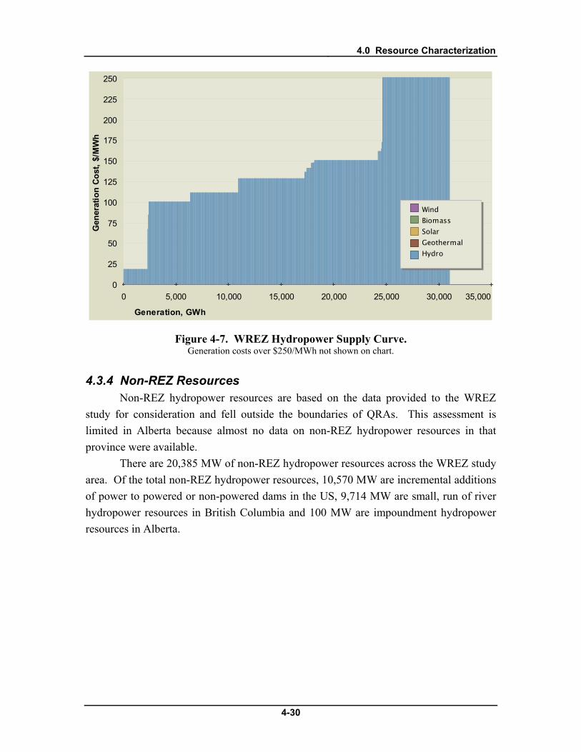
4.0 Resource Characterization
4-30
0 5,000 10,000 15,000 20,000 25,000 30,000 35,0000
25
50
75
100
125
150
175
200
225
250
Generation, GWh
Gen
erat
ion
Cost
, $/M
Wh
Wind Biomass Solar Geothermal Hydro
Figure 4-7. WREZ Hydropower Supply Curve. Generation costs over $250/MWh not shown on chart.
4.3.4 Non-REZ Resources Non-REZ hydropower resources are based on the data provided to the WREZ
study for consideration and fell outside the boundaries of QRAs. This assessment is limited in Alberta because almost no data on non-REZ hydropower resources in that province were available.
There are 20,385 MW of non-REZ hydropower resources across the WREZ study area. Of the total non-REZ hydropower resources, 10,570 MW are incremental additions of power to powered or non-powered dams in the US, 9,714 MW are small, run of river hydropower resources in British Columbia and 100 MW are impoundment hydropower resources in Alberta.
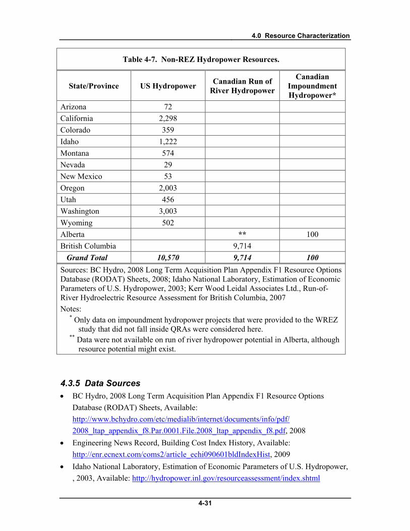
4.0 Resource Characterization
4-31
Table 4-7. Non-REZ Hydropower Resources.
State/Province US Hydropower Canadian Run of River Hydropower
Canadian Impoundment Hydropower*
Arizona 72 California 2,298 Colorado 359 Idaho 1,222 Montana 574 Nevada 29 New Mexico 53 Oregon 2,003 Utah 456 Washington 3,003 Wyoming 502 Alberta ** 100 British Columbia 9,714 Grand Total 10,570 9,714 100 Sources: BC Hydro, 2008 Long Term Acquisition Plan Appendix F1 Resource Options Database (RODAT) Sheets, 2008; Idaho National Laboratory, Estimation of Economic Parameters of U.S. Hydropower, 2003; Kerr Wood Leidal Associates Ltd., Run-of-River Hydroelectric Resource Assessment for British Columbia, 2007 Notes:
* Only data on impoundment hydropower projects that were provided to the WREZ study that did not fall inside QRAs were considered here.
** Data were not available on run of river hydropower potential in Alberta, although resource potential might exist.
4.3.5 Data Sources • BC Hydro, 2008 Long Term Acquisition Plan Appendix F1 Resource Options
Database (RODAT) Sheets, Available: http://www.bchydro.com/etc/medialib/internet/documents/info/pdf/ 2008_ltap_appendix_f8.Par.0001.File.2008_ltap_appendix_f8.pdf, 2008
• Engineering News Record, Building Cost Index History, Available: http://enr.ecnext.com/coms2/article_echi090601bldIndexHist, 2009
• Idaho National Laboratory, Estimation of Economic Parameters of U.S. Hydropower, , 2003, Available: http://hydropower.inl.gov/resourceassessment/index.shtml

4.0 Resource Characterization
4-32
• Kerr Wood Leidal Associates Ltd., Run-of-River Hydroelectric Resource Assessment for British Columbia, Available: http://www.bchydro.com/etc/medialib/internet/documents/info/pdf/ 2008_ltap_appendix_f5.Par.0001.File.2008_ltap_appendix_f5.pdf, 2007
• Personal communication with Edward Higginbottom, Senior Strategy Advisor, British Columbia Transmission Corporation, January 2009
• Personal communication with Bevan Laing, Senior Manager, Generation, Infrastructure Policy, Government of Alberta Department of Energy, May 2009
• Personal Communication with Edward Higginbottom, Senior Strategy Advisor, British Columbia Transmission Corporation and Allan Woo, BC Hydro, February 2009
• Personal communication with Kathy Lee, Senior Resource Planning Engineer, BC Hydro, February 2009
• Western Governor’s Association, WREZ Technology Assumptions for Supply Curve Analysis, Available: http://westgov.org/wga/initiatives/wrez/zita/Technology%20Assumption%20-%20Supply%20Curve%20TCversion.pdf, January 2009

4.0 Resource Characterization
4-33
4.4 Solar Solar is a primary resource in the WREZ study area. QRA boundaries were
defined based on the location of large amounts of high quality solar resource. The solar resource assessment approach was to quantify solar resource potential across the WREZ study area and reduce it to an assumed developable potential by removing lands that are undevelopable. A single solar resource dataset was available for the entire WREZ study area in the form of large scale solar resource maps from NREL. Various resource quality constraints were applied to these data and various environmental and technical exclusions were removed. A discount factor was applied to the remaining resource potential and the amount of resource potential in each grid square was quantified.
4.4.1 Resource Assessment Methodology The solar resource assessment identified solar resources potentially developable
as utility-scale solar projects. A direct normal insolation (DNI) level of 6.5 kWh/m2/day was assumed to be an appropriate overall minimum DNI threshold that could be cost-effectively developed on a utility scale, although higher minimum DNI level thresholds were applied to solar resources in different states. This differentiation was made due to the vast disparities in the quality and quantity of solar resources across the western US and Baja. States such as Arizona and New Mexico have large quantities of potentially developable, high quality solar, while states such as Colorado and Utah have lower quality resources. A minimum threshold was applied in an effort to focus the analysis on resources that would most likely be developed for export across state lines.
Table 4-8. Minimum Solar DNI Level by State.
State/Province Minimum DNI Level Considered in WREZ Analysis (kWh/m2/day)
Arizona 7.25 Baja California 7 California 7 Colorado 7 New Mexico 7 Nevada 7 Utah 6.5 Texas 6.5
4.0 Resource Characterization
4-34
Certain areas were assumed to be undevelopable for solar resources. It was assumed that it would be too expensive to develop solar on land with a terrain slope greater than 2 percent, so areas with these slope characteristics were excluded from the solar resource analysis. Water bodies, urban areas and military bases were assumed to be undevelopable and were excluded from consideration. Certain other areas were excluded in accordance with recommendations from the E&L working group.
To calculate the solar resource capacity potential (in MW) inside each grid square in the WREZ study area, it was assumed that each square kilometer of eligible solar DNI level resource contained 38.6 MW of generation potential, based on Black & Veatch research. Using this assumption, the acreage of each eligible, solar DNI level in each grid square was quantified and converted to generating capacity. The solar generating capacity quantified in each grid square was discounted by 96.5 percent to account for unknown developability constraints and to simplify the modeling for resource planning.
This discount factor was vetted and agreed upon by the ZITA group stakeholders, although it was somewhat arbitrary. While it was necessary to create a discount of some sort to account for these unknown constraints, there was limited empirical data and industry experience on which to base this discount. In lieu of an empirical approach, the discount was developed by consensus by the ZITA working group. This factor yields a rough parity between the best solar resource areas and the best wind resource areas with respect to the amount of capacity developable on tracts of similar size. Stakeholders decided that this discount was large enough to both account for developability constraints and make the results of the resource assessment useful for resource planners. No discount or a less severe discount could have resulted in millions of MW of resource potential across the WECC, rather than tens of thousands.
Due to the fact that multiple types of solar technology are suitable for each developable area, multiple types of solar were modeled for each area. As a result, users of the GTM model can select which type of solar technology they would like to model for each solar resource area. Users cannot double count the resource by selecting multiple technologies for a single resource, but they can choose which technology they would like to use to convert a certain amount of resource into electricity. Each of these technologies has different performance and economic characteristics, which are detailed below.
Solar Resource Map A map of all WREZ solar resources assessed is shown below in Figure 4-8. This
map shows solar resources at DNI levels 6.5 kWh/m2/day and above for US states and Baja Mexico filtered for applicable environmental, land use and technical exclusion areas.

4.0 Resource Characterization
4-35
Figure 4-8. Solar Resource Map.
4.0 Resource Characterization
4-36
4.4.2 Resource Supply Curve Characteristics Six different types of solar technology were modeled as part of the WREZ
analysis so that users of the WREZ Generation & Transmission model can select which of these technologies they want to model. These six technologies included four types of parabolic trough concentrating solar thermal technologies: dry-cooled with no storage, dry-cooled with six hours of thermal storage, wet-cooled with no storage and wet-cooled with six hours of thermal storage. They also included two types of solar photovoltaic (PV) technology: fixed-tilt thin film and tracking crystalline. Areas that were appropriate for solar thermal development were also appropriate for all large scale solar development. For this reason, areas that fit the criteria for solar thermal are characterized as each type of solar thermal and each type of solar PV.
The solar resource in each grid square was individually characterized to determine its levelized cost of energy. The following section outlines the assumptions that were made in the characterization of solar projects. Capital and Operating Costs
A capital cost and generation tie line (gen-tie) cost were assigned to all solar technologies in all QRAs across the WREZ study area. Capital costs were based on an assumed 200 MW project size. A base capital cost of per kW was assumed to be typical of the all-in cost per kW of each type of solar technology across the WREZ study area. This cost was based on Black & Veatch industry experience with real and planned solar projects and solar industry stakeholder input through the WREZ initiative.
Generation tie-line costs were calculated for solar resources in each QRA and added to the capital cost. These were calculated for each QRA based on the average distance from the centroid of each grid square to the nearest substation at least 115 kV in size. The interconnecting gen-tie lines were assumed to be 115 kV with a maximum line loading of 200 MW and a base cost of $750,000 per mile. This cost was based on Black & Veatch experience with transmission facilities of this size. The generation tie-line costs for solar resources from each QRA ranged from approximately $45/kW to $250/kW for QRAs located in very remote areas.
Fixed operations and maintenance costs were also assessed for each technology and used in the cost of generation calculations. Table 4-9 shows the base capital and operating cost assumptions for each solar technology, not including generation tie-line costs.

4.0 Resource Characterization
4-37
Table 4-9. Solar Technology Costs Used in the WREZ Analysis.
Base Capital Cost ($/kW)
Variable O&M Cost ($/kW-yr)
Solar Thermal Dry-Cooled No Thermal Storage 5,300 66
Solar Thermal Dry-Cooled 6 Hrs Thermal Storage 7,600 66
Solar Thermal Wet-Cooled No Thermal Storage 5,100 66
Solar Thermal Wet-Cooled 6 Hrs Thermal Storage 7,400 66
Solar Thin-Film Fixed PV* 4,500 50 Solar Crystalline Tracking PV* 5,700 65 Source: Black & Veatch research for Phase 1 of the WREZ Initiative. Notes:
* Solar PV values on a kWe and net AC basis.
Production Profile Thermal and photovoltaic technologies each had its own production profile
methodology.
Solar Thermal All solar thermal projects were modeled as parabolic trough plants either dry or
wet cooled and with or without storage. A production profile was created for various DNI levels throughout each QRA and assigned to all resources in that QRA within that DNI level. In order to do this, the median DNI level was found for each QRA grid square containing solar resources. Each QRA grid square containing solar resources was assigned one of five DNI level “buckets” from 6.5 to greater than 7.5, with breaks of 0.25 kWh/m2/day. A 12x24 production profile was then calculated for the centroid of all of the grid squares in each of these buckets in each QRA. This profile was then assigned to all grid squares in that bucket in that QRA. The capacity factor was derived as the arithmetic mean of each profile.
Solar Photovoltaic For solar PV technologies, 12x24 production profiles and capacity factors were
calculated for each QRA’s centroid and applied to all resources inside that QRA. For a

4.0 Resource Characterization
4-38
solar photovoltaic project, capacity factor is the ratio of its AC delivered energy over a year and its AC energy output if it had operated at full nameplate capacity the entire time.
Black & Veatch used data and models developed by the National Renewable Energy Laboratory (NREL) as a basis for the capacity factor analysis for photovoltaic modules. NREL provided high resolution solar irradiance data in GIS format. This data included global horizontal, latitude tilt and direct normal monthly irradiance values for 10km x 10km grid squares. NREL derived the solar irradiance data from many years of satellite images covering the United States.
Black & Veatch used a proprietary tool to calculate energy production. The inputs for this tool included the NREL solar irradiance data, temperature data, geographical location, day and hour. The tool outputs average hourly energy production by month for both tracking crystalline silicon and fixed tilt thin film technologies.
Figure 4-9 and Figure 4-10 show examples of the daily energy generation profiles for single axis tracking and fixed tilt technologies. A single axis tracking system produces more energy in the mornings and afternoons than a fixed tilt system. The example daily energy generation profile in Figure 4-9 shows a July profile for crystalline and thin film. The thin film generation peak is above the crystalline peak for two major reasons. The first is that thin film has a lower temperature coefficient, which means that it suffers less from mid-day high temperatures than crystalline. The second is that the fixed tilt angle of thin film is more optimally pointed toward the sun than the flat horizontal tilt of crystalline at mid-day.

4.0 Resource Characterization
4-39
-0.2
0
0.2
0.4
0.6
0.8
1
1.2
0 5 10 15 20
Hour
W/W
pThin Film: 20 Degree Fixed TiltCystalline: One-Axis Tracking
Figure 4-9. Example Energy Output from Tracking Crystalline and Fixed Tilt Thin Film (July).
-0.2
0
0.2
0.4
0.6
0.8
1
1.2
0 5 10 15 20
Hour
W/W
p
Thin Film: 20 Degree Fixed TiltCystalline: One-Axis Tracking
Figure 4-10. Example Energy Output from Tracking Crystalline and Fixed Tilt Thin Film (December).

4.0 Resource Characterization
4-40
4.4.3 Results Over 86,000 MW of developable solar resources were identified in QRAs across
the WREZ study area, with a total theoretical annual capacity of 190 to 270 TWh per year, dependent on the solar technology.40
Of this resource potential, over 40,000 MW were between DNI levels of 7.25 and 7.5 kWh/m2/day, over 26,000 MW were between 7.0 and 7.25, and the remainder fell into the other DNI classes. Of the states with solar resources, Arizona, California and Nevada had the most resource potential and the highest theoretical annual generation.
0
5,000
10,000
15,000
20,000
25,000
30,000
35,000
40,000
45,000
50,000
AZ CA CO ID MT NM NV OR TX UT WA WY AB BC BJ
Pote
ntia
l Sol
ar C
apac
ity p
er R
egio
n, M
W (A
ssum
ing
96.5
% D
isco
unt)
6.5 - 6.756.75 - 7.07.0 - 7.257.25 - 7.57.5 +
Direct Normal Insolation,kWh/m2/day
Figure 4-11. WREZ Solar Capacity by State/Province and DNI Level.
Economic Analysis The levelized cost of energy of solar resources across the WREZ study area
ranged from $148/MWh to $312/MWh. The levelized cost of energy varies across the WREZ study area and across different solar technologies. Wet cooled solar thermal with storage tends to produce the cheapest energy, while tracking crystalline PV tends to produce the most expensive energy. Variation in capacity factor and variation in capital costs due to different assumed generation tie-line lengths among QRAs have the greatest effects on the cost of generation of solar energy within technologies. Variation in tax incentives available for solar in the US and Mexico also have an effect on the cost of
40 Some solar technologies assessed in this study have higher capacity factors than others, resulting in variation in annual generation potential.

4.0 Resource Characterization
4-41
energy from solar resources. Capital costs, including generation tie-lines, ranged from $4,546/kW to $7,852/kW. Capital costs vary from the base costs shown above due to variation in the average length of generation tie lines across QRAs.
Table 4-10 summarizes solar performance and economic results. Figure 4-12 is a supply curve of dry-cooled solar thermal resources with six hours of storage in QRAs across the WREZ study area.
Table 4-10. Summary of Solar Performance and Economics Results.
Resource Type ST Dry
No Storage
ST Dry 6 hrs
Storage
ST Wet No
Storage
ST Wet 6 hrs
Storage
Fixed Thin-
Film PV*
Tracking Cryst. PV*
Performance Capacity Factor (percent) 20 to 28 29 to 39 22 to 30 29 to 42 22 to 27 26 to 31
Economics All-in Capital Cost ($/kW, including gen. tie line cost)
5,346 to 5,552
7,646 to 7,852
5,146 to 5,352
7,446 to 7,652
4,546 to 4,752
5,746 to 5,952
Gen. Tie Line Cost ($/kW) 46 to 252 46 to 252 46 to 252 46 to 252 46 to 252 46 to 252
Fixed O&M Cost ($/kW-yr) 66 66 66 66 50 65
Levelized Cost of Energy ($/MWh)
168 to 291
162 to 284
152 to 269
148 to 269
176 to 284
191 to 312
Source: Black & Veatch analysis for Phase 1 of the WREZ Initiative. Notes:
* All values for solar PV on a kWe, and net AC basis

4.0 Resource Characterization
4-42
0 50,000 100,000 150,000 200,000 250,000 300,0000
25
50
75
100
125
150
175
200
225
250
Generation, GWh
Gen
erat
ion
Cost
, $/M
Wh
Wind Biomass Solar Geothermal Hydro
Figure 4-12. WREZ Solar Thermal Supply Curve.
4.4.4 Non-REZ Resources There are over 416 GW of non-REZ solar thermal resources and over 750 GW
of non-REZ solar photovoltaic resources across the WECC. These estimates exclude all applicable environmental and technical screens and apply a 96.5 percent discount factor to all solar resources. Solar thermal resources were quantified at DNI levels of 4.5 kWh/m2/day and above and solar photovoltaic resources were quantified at all global horizontal insolation (GHI) levels.
The greatest non-REZ solar thermal resource potential is in Colorado, Nevada and California. Note that the majority of the non-REZ solar thermal resources in these and almost every state (except for Baja and New Mexico) fall in the 4.5-6.5 kWh/m2/day DNI range. This range is below the minimum DNI level of resources considered REZ resources.
The greatest non-REZ solar photovoltaic resource potential is in New Mexico, Montana and Arizona. These resources were not classified into different GHI “buckets,” but their mean GHI levels were calculated, and are suggestive of the overall quality of the non-REZ resource in each state. Although Montana has among the highest non-REZ solar photovoltaic resources, it has among the lowest mean GHI levels, which suggests that it has poorer solar photovoltaic resources than other states.
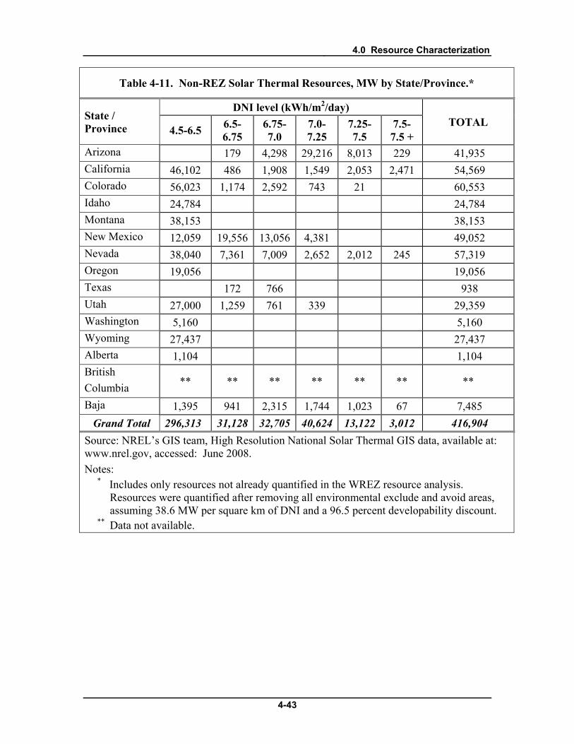
4.0 Resource Characterization
4-43
Table 4-11. Non-REZ Solar Thermal Resources, MW by State/Province.*
State / Province
DNI level (kWh/m2/day) TOTAL
4.5-6.5 6.5-6.75
6.75-7.0
7.0-7.25
7.25-7.5
7.5-7.5 +
Arizona 179 4,298 29,216 8,013 229 41,935 California 46,102 486 1,908 1,549 2,053 2,471 54,569 Colorado 56,023 1,174 2,592 743 21 60,553 Idaho 24,784 24,784 Montana 38,153 38,153 New Mexico 12,059 19,556 13,056 4,381 49,052 Nevada 38,040 7,361 7,009 2,652 2,012 245 57,319 Oregon 19,056 19,056 Texas 172 766 938 Utah 27,000 1,259 761 339 29,359 Washington 5,160 5,160 Wyoming 27,437 27,437 Alberta 1,104 1,104 British Columbia ** ** ** ** ** ** **
Baja 1,395 941 2,315 1,744 1,023 67 7,485 Grand Total 296,313 31,128 32,705 40,624 13,122 3,012 416,904 Source: NREL’s GIS team, High Resolution National Solar Thermal GIS data, available at: www.nrel.gov, accessed: June 2008. Notes:
* Includes only resources not already quantified in the WREZ resource analysis. Resources were quantified after removing all environmental exclude and avoid areas, assuming 38.6 MW per square km of DNI and a 96.5 percent developability discount.
** Data not available.

4.0 Resource Characterization
4-44
Table 4-12. Non-REZ Solar Photovoltaic Resource by State/Province.*
State/Province TOTAL MW All GHI Levels**
Mean GHI Level kWh/m2/day
Arizona 86,989 5.5 California 29,355 5.2 Colorado 47,083 4.9 Idaho 25,794 4.4 Montana 123,085 3.9 New Mexico 126,150 5.4 Nevada 41,217 5.0 Oregon 48,689 4.4 Texas 11,951 5.7 Utah 33,955 4.9 Washington 30,613 3.9 Wyoming 84,025 4.5 Alberta 25,501 3.6 British Columbia 20,985 3.4 Baja 17,994 5.7 Grand Total 753,384 N/A Source: NREL’s GIS team, High Resolution National Solar Photovoltaic GIS data, available at: www.nrel.gov, accessed: June 2008. Note:
* Includes only resources not already quantified in the WREZ resource analysis. Resources were quantified after removing all environmental exclude and avoid areas, assuming 38.6 MW per square km of GHI and a 96.5 percent developability discount.
** Estimates of non-REZ solar PV potential and solar thermal potential are mutually exclusive. It was assumed that non-REZ PV could be built anywhere non-REZ solar thermal could be built, so the non-REZ solar thermal potential was subtracted from the non-REZ PV potential, so as not to double count the potentially available resources.
4.4.5 Data Sources Data sources used in this analysis included:

4.0 Resource Characterization
4-45
• Blair, et.al., Modeling Photovoltaic and Concentrating Solar Power Trough Performance, Cost, and Financing with the Solar Advisor Model, available at: www.nrel.gov, accessed: June 2008
• R. Bird and C. Riordan, Simple Spectral Model for Direct and Diffuse Irradiance on Horizontal and Tilted Planes at the Earth's Surface for Cloudless Atmospheres, available: www.nrel.gov, accessed: June 2008
• Perez, et.al., SUNY Satellite Solar Radiation model, available: www.nrel.gov, accessed: June 2008
• NREL’s GIS team, High Resolution National Solar Photovoltaic and Solar Thermal GIS data, available: www.nrel.gov, accessed: June 2008

4.0 Resource Characterization
4-46
4.5 Wind The assessment of wind resources across the WREZ study region was based on
three different wind resource datasets. A single, consistent wind power dataset was not available for the entire WREZ study area. In the US and Baja California Norte, Mexico (“Baja”), wind resource potential was quantified across large areas and reduced to an assumed developable potential. Large scale wind power maps from NREL were used for the entire US portion of the WREZ study area. The Canadian wind resource analysis identified specific planned or theoretical projects. A study of wind resources across the lower two thirds of British Columbia (BC) by BC Hydro was used to identify BC wind resources.41 In Alberta, data on planned wind projects that have applied for transmission interconnection from the Canadian Wind Energy Association (CanWEA) and the South Eastern Energy Developers (SEED) were used to identify resources in the province.42
It was not possible to assess wind resources in BC and Alberta using the same methodology used in the US. Wind power data for the majority of British Columbia were created as part of the BC Hydro wind study, but consultation with the study’s authors revealed these data were consistently inaccurate in some regions. As a result, they were not comparable to the NREL data used for the US assessment without adjustments. These adjustments could not be made at the level of resolution of the US WREZ wind power analysis; but needed to be made at the project level. The WREZ process accepted this different resource assessment methodology because it provided the most accurate data possible for BC. Wind power data were not available for Alberta, so the resource assessment was based on planned wind projects.
In light of the fact that the US and Canadian resource assessment approaches are fundamentally different, efforts were made to ensure the comparability of the results. The US assessment quantified the wind power potential across large areas and removed the resource potential located on technically undevelopable lands, areas where development would not be economically feasible and areas where development was not feasible due to statute, regulation or environmental sensitivity. The remaining potential was then discounted to reflect unknown development constraints, and the fact that only a fraction of developable wind resources in an area have historically been developed. The BC and Alberta resource assessments used data for specific delineated theoretical (in BC) or planned (in Alberta) projects. These assessments represent specific potential projects
41 BC Hydro, BC Wind Data Study, Available: http://www.bchydro.com/planning_regulatory/energy_technologies/wind_energy/wind_data_study.html, May 2009 42 CanWEA and SEED, “SE Area Wind Power Projects – Transmission Connected,” received from Claude Mindorff or Mainstream Energy, November 2008.

4.0 Resource Characterization
4-47
that already take many developability constraints into account. As a result, the resource potential identified in the Canadian assessments was not discounted at all.
4.5.1 Resource Assessment Methodology
US / Baja The US and Baja wind resource assessment identified wind resources potentially
developable as utility-scale wind projects. NREL wind power class 3 was assumed to be an appropriate overall minimum wind power threshold that could be cost-effectively developed on a utility scale, although higher minimum wind power class thresholds were applied to wind resources in different states. This differentiation was made due to the vast disparities in the quality and quantity of wind resources across the western US and Baja. States such as Montana and Wyoming have large quantities of potentially developable, high quality (Class 5) wind, while states such as Utah and Washington may not. A minimum threshold was applied in an effort to focus the analysis on resources that would most likely be developed for export across state lines.
Table 4-13. Minimum Wind Power Class by State.
State/Province Minimum Wind Power Class Considered in WREZ Analysis
Montana 5 Wyoming 5 Baja California Norte 4 Colorado 4 New Mexico 4 Texas 4 Arizona 3 California 3 Idaho 3 Nevada 3 Oregon 3 Utah 3 Washington 3
Certain areas were assumed to be undevelopable for wind resources. It was
assumed that it would be too expensive to develop wind on land with a terrain slope greater than 20 percent. Areas with these slope characteristics were excluded from the

4.0 Resource Characterization
4-48
wind resource analysis. Water bodies, urban areas and military bases were assumed to be undevelopable and were excluded from consideration. Areas designated as environmental “exclude” and “avoid” areas by the Environment and Lands (E&L) working group were also excluded.
To calculate the wind resource capacity potential (in MW) inside each grid square for the US portion of the WREZ study area, it was assumed that each square kilometer of eligible wind power class resource contained 5 MW of generation potential. Using this assumption, the amount of land by wind class in each grid square was quantified and converted to generating capacity. As discussed in Chapter 3.0, the wind power capacity identified in each grid square was discounted by 75 percent to account for unknown developability constraints. This discount factor was agreed upon by the ZITA group stakeholders as representative of experience in the wind industry.
Canada
British Columbia Resource Potential Identification Approach The British Columbia wind resource analysis relied on the projects delineated in
the BC Hydro wind data study. Black & Veatch received GIS data on project locations, capacity factors and annual generation profiles for each project from BC Hydro.43
Alberta Resource Potential Identification Approach
Consultation with BC Hydro staff revealed that these BC projects already took into account a number of technical and developability exclusions. For this reason, none of the technical and developability exclusions that were applied to the rest of the WREZ study area were applied to the BC projects. These projects also took into account a number of environmental exclusions. An analysis of where these projects intersected with the environmental exclusions developed by the environment and lands group for WREZ was conducted. There were a few places where overlap did occur. BC Hydro was made aware of these overlaps, adjusted the affected projects and provided revised GIS and capacity data to Black & Veatch for the final analysis.
The Alberta wind resources analysis relied on project locations and capacities provided in a memorandum by the Canadian Wind Energy Association (CanWEA) and the South Eastern Energy Developers (SEED), in Alberta. Black & Veatch received latitude and longitude coordinates for each of 36 projects identified in this memorandum. Unlike the British Columbia projects, these project locations were approximate and showed the general locations of projects. CanWEA and SEED advised Black & Veatch 43 Personal communication with Magdalena Rucker, Energy Planning, BC Hydro, May 2009

4.0 Resource Characterization
4-49
that these projects were far enough along in their development that technical and developability exclusions did not need to be applied. Any apparent overlap with environmental exclusions of the GIS dataset was likely due to the approximate nature of the project coordinates. Any observed overlaps were brought to the attention of the CanWEA and SEED data coordinator, Claude Mindorff of Mainstream Energy44
In British Columbia and Alberta, the MW potential of projects was attributed to the grid square in which the centroid of each project was located. Wind resource potential in British Columbia and Alberta was not discounted, as is explained above.
to determine whether the projects in question did actually fall inside these environmental exclusion areas.
Wind Resource Map A map of all wind resources assessed is shown below in Figure 4-13. This map
shows wind resources class 3 and above for all US states and Baja Mexico filtered for applicable environmental, land use and technical exclusion areas. It also shows the location of the Canadian wind projects that were assessed.
44 Personal communication with Claude Mindorff, Vice President of Business Development, Mainstream Renewable Power LLC, March 2009

4.0 Resource Characterization
4-50
Figure 4-13. Wind Resource Map.
4.0 Resource Characterization
4-51
4.5.2 Resource Supply Curve Characteristics
Capital Cost A capital cost and generation tie line (gen-tie) cost were assigned to all wind
resources across the WREZ study area. Capital costs were based on an assumed 100-200 MW project size. A base cost of $2,300 per kW was assumed to be typical of the all-in cost per kW of wind resources across the WREZ study area. This cost was based on Black & Veatch industry experience with real wind projects of this size and wind industry stakeholder input through the WREZ initiative.
Generation tie-line costs were calculated for wind resources in each QRA and added to the capital cost. These were calculated for each QRA based on the average distance from the centroid of each grid square to the nearest substation at least 115 kV in size. The interconnecting gen-tie lines were assumed to be 115 kV with a maximum line loading of 200 MW and a base cost of $750,000 per mile. This cost was based on Black & Veatch experience with transmission facilities of this size. The generation tie-line costs for wind resources from each QRA ranged from approximately $40/kW to $400/kW for QRAs located in very remote areas.
Operating Costs Operations and maintenance costs were assumed to be $60 / kW-year. This cost
was calculated from Black & Veatch industry experience with projects of a similar size.
Capacity Factor To calculate the annual wind energy generating potential (in GWh/yr) inside each grid square, a capacity factor was calculated for each grid square. A representative capacity factor was assigned to each wind power class, as shown in Table 4-14. In the US, the capacity factor for each grid square was calculated as the capacity-weighted average capacity factor of the wind power classes in each grid square. In British Columbia and Alberta, capacity factors were provided for the specific projects identified by BC Hydro and CanWEA/SEED. These were attributed to the grid squares in which the centroid of each projects was located.
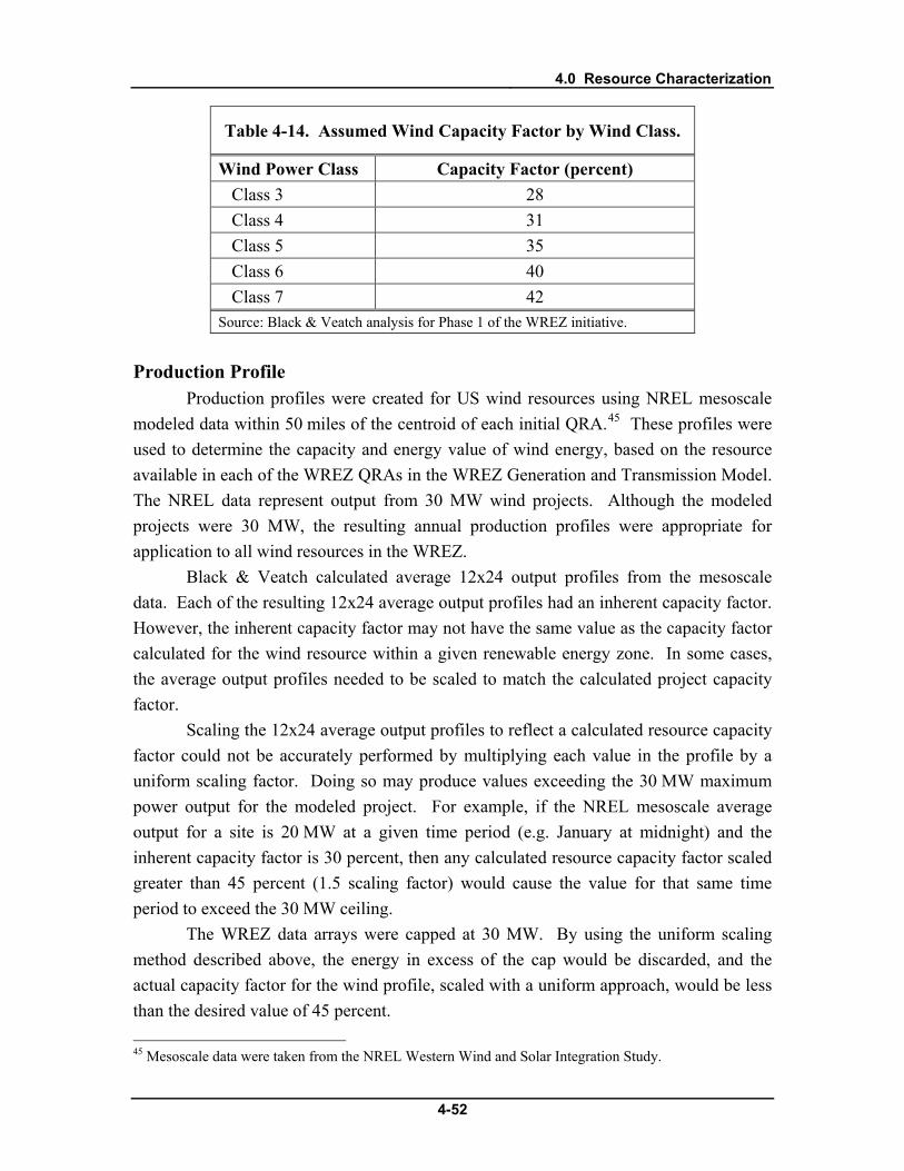
4.0 Resource Characterization
4-52
Table 4-14. Assumed Wind Capacity Factor by Wind Class.
Wind Power Class Capacity Factor (percent) Class 3 28 Class 4 31 Class 5 35 Class 6 40 Class 7 42
Source: Black & Veatch analysis for Phase 1 of the WREZ initiative.
Production Profile Production profiles were created for US wind resources using NREL mesoscale
modeled data within 50 miles of the centroid of each initial QRA.45
Black & Veatch calculated average 12x24 output profiles from the mesoscale data. Each of the resulting 12x24 average output profiles had an inherent capacity factor. However, the inherent capacity factor may not have the same value as the capacity factor calculated for the wind resource within a given renewable energy zone. In some cases, the average output profiles needed to be scaled to match the calculated project capacity factor.
These profiles were used to determine the capacity and energy value of wind energy, based on the resource available in each of the WREZ QRAs in the WREZ Generation and Transmission Model. The NREL data represent output from 30 MW wind projects. Although the modeled projects were 30 MW, the resulting annual production profiles were appropriate for application to all wind resources in the WREZ.
Scaling the 12x24 average output profiles to reflect a calculated resource capacity factor could not be accurately performed by multiplying each value in the profile by a uniform scaling factor. Doing so may produce values exceeding the 30 MW maximum power output for the modeled project. For example, if the NREL mesoscale average output for a site is 20 MW at a given time period (e.g. January at midnight) and the inherent capacity factor is 30 percent, then any calculated resource capacity factor scaled greater than 45 percent (1.5 scaling factor) would cause the value for that same time period to exceed the 30 MW ceiling.
The WREZ data arrays were capped at 30 MW. By using the uniform scaling method described above, the energy in excess of the cap would be discarded, and the actual capacity factor for the wind profile, scaled with a uniform approach, would be less than the desired value of 45 percent. 45 Mesoscale data were taken from the NREL Western Wind and Solar Integration Study.
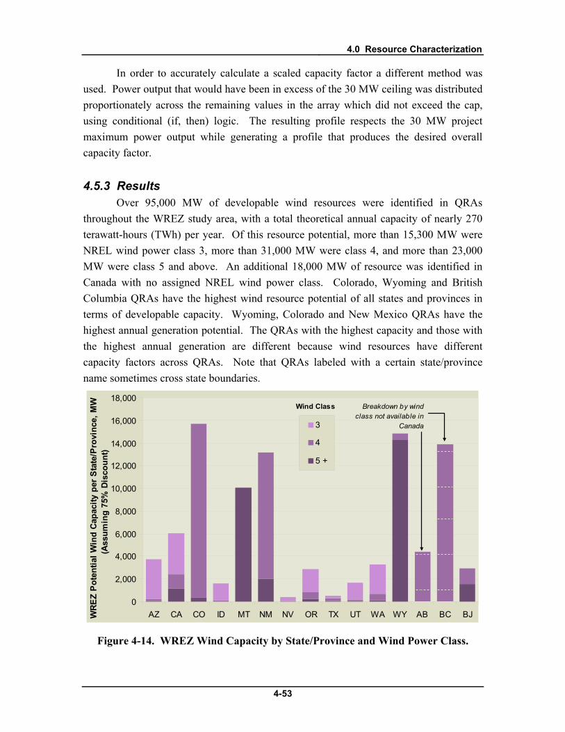
4.0 Resource Characterization
4-53
In order to accurately calculate a scaled capacity factor a different method was used. Power output that would have been in excess of the 30 MW ceiling was distributed proportionately across the remaining values in the array which did not exceed the cap, using conditional (if, then) logic. The resulting profile respects the 30 MW project maximum power output while generating a profile that produces the desired overall capacity factor.
4.5.3 Results Over 95,000 MW of developable wind resources were identified in QRAs
throughout the WREZ study area, with a total theoretical annual capacity of nearly 270 terawatt-hours (TWh) per year. Of this resource potential, more than 15,300 MW were NREL wind power class 3, more than 31,000 MW were class 4, and more than 23,000 MW were class 5 and above. An additional 18,000 MW of resource was identified in Canada with no assigned NREL wind power class. Colorado, Wyoming and British Columbia QRAs have the highest wind resource potential of all states and provinces in terms of developable capacity. Wyoming, Colorado and New Mexico QRAs have the highest annual generation potential. The QRAs with the highest capacity and those with the highest annual generation are different because wind resources have different capacity factors across QRAs. Note that QRAs labeled with a certain state/province name sometimes cross state boundaries.
0
2,000
4,000
6,000
8,000
10,000
12,000
14,000
16,000
18,000
AZ CA CO ID MT NM NV OR TX UT WA WY AB BC BJWRE
Z Po
tent
ial W
ind
Capa
city
per
Sta
te/P
rovi
nce,
MW
(Ass
umin
g 75
% D
isco
unt)
3
4
5 +
Wind Class Breakdown by wind class not available in
Canada
Figure 4-14. WREZ Wind Capacity by State/Province and Wind Power Class.
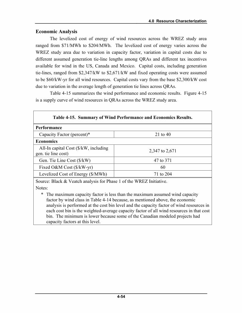
4.0 Resource Characterization
4-54
Economic Analysis The levelized cost of energy of wind resources across the WREZ study area
ranged from $71/MWh to $204/MWh. The levelized cost of energy varies across the WREZ study area due to variation in capacity factor, variation in capital costs due to different assumed generation tie-line lengths among QRAs and different tax incentives available for wind in the US, Canada and Mexico. Capital costs, including generation tie-lines, ranged from $2,347/kW to $2,671/kW and fixed operating costs were assumed to be $60/kW-yr for all wind resources. Capital costs vary from the base $2,300/kW cost due to variation in the average length of generation tie lines across QRAs.
Table 4-15 summarizes the wind performance and economic results. Figure 4-15 is a supply curve of wind resources in QRAs across the WREZ study area.
Table 4-15. Summary of Wind Performance and Economics Results.
Performance Capacity Factor (percent)* 21 to 40 Economics All-In capital Cost ($/kW, including gen. tie line cost) 2,347 to 2,671
Gen. Tie Line Cost ($/kW) 47 to 371 Fixed O&M Cost ($/kW-yr) 60 Levelized Cost of Energy ($/MWh) 71 to 204 Source: Black & Veatch analysis for Phase 1 of the WREZ Initiative. Notes:
* The maximum capacity factor is less than the maximum assumed wind capacity factor by wind class in Table 4-14 because, as mentioned above, the economic analysis is performed at the cost bin level and the capacity factor of wind resources in each cost bin is the weighted-average capacity factor of all wind resources in that cost bin. The minimum is lower because some of the Canadian modeled projects had capacity factors at this level.

4.0 Resource Characterization
4-55
0 50,000 100,000 150,000 200,000 250,000 300,0000
25
50
75
100
125
150
175
200
225
250
Generation, GWh
Gen
erat
ion
Cost
, $/M
Wh
Wind Biomass Solar Geothermal Hydro
Figure 4-15. WREZ Wind Supply Curve.
4.5.4 Non-REZ Resources Non-REZ wind resources were assessed for the entire WREZ study area. In the
US, all wind resources at NREL wind power class 3 and above that were not already quantified in the WREZ resource analysis were considered non-REZ wind in all states in the US and Baja. This analysis identified over 470,000 MW of non-REZ resources, after applying a 75 percent developability discount. In Canada, non-WREZ wind resource data were provided by two other studies, and these data were not broken out by wind class. The majority of the non-REZ resources were concentrated in a few states/provinces. Over 440,000 MW of these class 3 wind resources were in Alberta, Colorado, Montana, New Mexico and Wyoming. The non-REZ analysis also quantified nearly 100,000 MW of class 4 and over 17,000 MW of class 5 and above wind resources.

4.0 Resource Characterization
4-56
Table 4-16. Non-REZ Wind Resources, MW.a
State / Province Class 3 Class 4 Class 5+ TOTAL Arizona 1,924 293 121 2,338
California 5,134 1,434 694 7,262 Colorado 54,855 2,860 910 58,625
Idaho 5,170 623 329 6,122 Montana 141,308 52,113 2,590 196,011
New Mexico 60,827 4,333 697 65,857 Nevada 3,046 671 352 4,069 Oregon 7,796 1,419 654 9,869 Texas 364 35 23 422 Utah 1,588 377 224 2,189
Washington 2,618 811 496 3,925 Wyoming 65,251 32,362 10,175 107,788 Alberta b b b 120,000
British Columbia b b b 3,800c
Baja 5,176 708 285 6,169 Total 355,057 98,039 17,550 594,446
Source: NREL Wind Resource Maps, available at: http://www.eere.energy.gov/windandhydro/windpoweringamerica/wind_maps.asp, accessed: March 6th, 2008; Personal communication with Matthew Good, Alberta Department of Energy, August 2009; Personal communication with Magdalena Rucker, BC Hydro, September 2009. Notes:
a This chart includes NREL wind power class 3 and above resources that are not quantified in the REZ analysis.
b Non-REZ WREZ wind resource data not available by wind power class.
c Non-REZ wind data were taken from a much more refined analysis that delineated specific projects not originally identified in QRAs. Because it is closer to an estimate of non-REZ developable potential, non-REZ wind resources in BC are much smaller than those of many other states and provinces in the study.
4.5.5 Data Sources Data sources used in this analysis included:
4.0 Resource Characterization
4-57
• NREL Wind Resource Maps, available at: http://www.eere.energy.gov/windandhydro/windpoweringamerica/wind_maps.asp, accessed: March 6th, 2008
• NREL Mesoscale Wind Data, Available: http://www.nrel.gov/wind/integrationdatasets/western/methodology.html
• BC Hydro, BC Wind Data Study, Available: http://www.bchydro.com/planning_regulatory/energy_technologies/wind_energy/wind_data_study.html, May 2009
• CanWEA and SEED, “SE Area Wind Power Projects – Transmission Connected,” received from Claude Mindorff or Mainstream Energy, November 2008.
• Personal communication with Matthew Good, Alberta Department of Energy, August 2009

5.0 QRA and Non-REZ Analysis Results
5-1
5.0 QRA and Non-REZ Analysis Results
Fifty-three QRAs were identified across the WREZ study area, with nearly 200,000 MW of renewable energy resources theoretically capable of generating over 560 terawatt hours (TWh) of energy per year.46 Over 2,200,000 MW of non-REZ resources were also identified across the study area. To put these estimates in perspective, the entire WECC peak load in summer 2007 was 150,000 MW.47
This section presents maps generated for the WREZ analysis, a summary of the QRA and non-REZ analyses and a brief discussion of the renewable energy resources quantified in the analyses. A supply curve for each QRA was generated and is provided in Appendix A. Capacity and energy summary tables by resource and by QRA were generated and are provided in Appendix B.
5.1 QRA Maps Two main maps resulted from the WREZ process. The WREZ QRA map shows
the precise locations of the QRA boundaries identified in the QRA analysis. The WREZ hub map was created to represent resource concentrations in a general way through the visual image of hubs. The hub concept is explained in greater detail in Chapter 3.0.
5.1.1 WREZ QRA Map The WREZ QRA map shows the final boundaries of QRAs as identified in the
QRA analysis detailed in Chapter 3.0. It also shows the resources that were quantified in the QRA analysis as well as all other WREZ resources that met the minimum quality criteria for inclusion in the WREZ analysis after environmental and technical exclusion areas were removed. In an effort to keep the map simple and uncluttered, biomass resources are not shown. Biomass resources are shown in the biomass resource map in Chapter 4.0.
Note that QRA boundaries were developed to quantify the resources in an area for a screening level analysis. These boundaries are not intended to suggest that renewable resources inside a QRA should be developed first, that those areas outside of a QRA either should not or cannot be developed, or that a tract just inside a QRA boundary is superior to an adjacent tract that has similar characteristics but happens to be outside the
46 British Columbia provided a 54th QRA representing a shaped renewable energy product to load serving entities (LSEs) at the British Columbia-Washington border. This QRA is shown in the hub map and selectable in the GTM model. However, it was developed independently of the Black & Veatch/NREL QRA analysis outlined here, so it is not characterized here. 47 WREZ Zone Identification and Technical Analysis Working Group, Step 2: Filtering resource data into Candidate Study Areas, Available: http://www.westgov.org/wga/initiatives/wrez/zita/Step2.pdf, 2009.

5.0 QRA and Non-REZ Analysis Results
5-2
boundary. QRAs represent conceptual analytical areas created to estimate the resources available within an area for modeling purposes. They do not indicate actual planned transmission service to these areas or the location of planned transmission interconnection points, and renewable development is not precluded in other areas that do not fall inside QRA boundaries.

5.0 QRA and Non-REZ Analysis Results
5-3
Figure 5-1. WREZ QRA Map.
Texas
AlbertaBritish Columbia
Utah
California
Montana
Arizona
Idaho
Nevada
Oregon
Colorado
Wyoming
New Mexico
Washington
Baja California
AB_EA
BC_NW
BC_NO
BC_SW
BC_NE
TX
BC_SO
NM_EA
BC_SE
CO_SE
AB_SE
BC_WC
WY_EA
NM_SW
NV_WE
CA_WE
AZ_WE
BC_CT
BC_EA
UT_WE
CA_NE
NM_SO
AB_EC
WY_EC
AZ_SO
NV_SW
CO_EA
WA_SO
BJ_NO
MT_NW
WY_NO
CO_NEWY_SO
ID_SW
BC_WE
CA_EA
CA_SO
CO_SO
NM_SE
NV_EA
MT_NE
OR_NE
AZ_NW
BJ_SO
CA_CT AZ_NE
OR_SO
MT_CT
NM_CT
ID_EA
OR_WE
NV_NO
AB_NO
LegendQRA Boundaries
Hydro projects (MW)1 - 1010 - 100100 - 500500+
Geothermal projects (MW)8 - 1010 - 100100 - 500500+
Canadian wind projects
Wind resourceNREL wind power class (50m)
34567
Solar thermal resourceDNI (kWh/sqmtr/day)
6.5 - 6.756.75 - 77 - 7.257.25 - 7.57.5+
0 50 100 150 20025Miles
WREZ Initiative QRA MapThe following text is DRAFT
Qualified Resource Areas (QRAs) are areas of regional renewable resource potential in the WesternInterconnection, identified for purposes of evaluating interstate transmission lines in future phases ofthe initiative. QRAs were developed under the assumptions used in the WREZ initiative. Beyond thespecific exclusions identified in the WREZ analysis, there has been little consideration of constructionlogistics or costs, permitting or cultural or other land use concerns related to the specific sites in theidentification of QRA boundaries.These boundaries are not intended to suggest that renewable resources inside a QRA should bedeveloped first, or that those areas outside of a QRA either should or cannot be developed. QRAsrepresent physical boundaries created for to quantify the resources available within an area formodeling purposes. QRAs do not indicate actual planned transmission service to these areas or thelocation of planned transmission interconnection points, and renewable development is not precluded inother areas that do not fall inside QRA boundaries.All resources that meet the minimum quality thresholds defined by the Zone Identification and TechnicalAnalysis working group for inclusion in this study are shown on this map. However, the resources thatare quantified inside each QRA include only the highest-quality wind and solar resources in each stateor province, as well as geothermal sites, biomass and hydropower with known commercial potential.Theminimum wind and solar resource quality criteria vary in each state. For instance, only wind resourceareas that are wind power class 5 and above count toward the estimates for Wyoming and Montanadue to the abundance of high-quality wind resources in these states. In other states where the windquality is generally lower, the thresholds are also lower.Resources that do not meet the state-by-state or general quality thresholds are quantified in theWREZreport as “non-WREZ” resources.These include low quality wind, solar thermal, solar PV,undiscovered conventional geothermal potential, enhanced geothermal systems and all other viablerenewable resources.The assessment of conventional geothermal resources is limited to BC,CA,ID,NV,OR and UT due to theknown high potential of conventional geothermal resources in these states and provinces. Biomassresources are quantified as part of the WREZ supply curve analysis for each QRA, although theseresources are not shown on this map.The U.S.hydropower resource assessment is preliminary andbased on data thathave not been validated or may be out of date.Therefore, both the location and thegenerating potential of U.S.hydropower resources shown on this map are highly uncertain. Hydropower
Alberta: Wildlife and land-use concerns are addressed on a project specific basis through the environmental impact assessment process.Arizona: Arizona’s “hubs” represent areas of high-quality renewable energy resources for purposes of evaluating interstate transmission lines. This representation is not intended to suggest that renewable development should occur solely within these “hubs.”Proper site selection for renewable energy generation facilities and associated transmission lines within and outside these “hubs” should include consultation with the Arizona Game and Fish Department and other relevant agencies for wildlife and environmentalinformation. Stakeholders are participating in Arizona’s Renewable Transmission Task Force (RTTF) process to more precisely evaluate identified renewable energy zones and develop appropriate transmission plans. Further information is available athttp://www.azcc.gov/divisions/utilities/electric/Biennial.asp.British Columbia: British Columbia’s map includes 10 hubs, representing the province’s 10 Qualified Resource Areas. British Columbia’s map also includes a separate hub on the British Columbia-Washington border that represents a 16,000 gigawatt-hourshaped energy product. The intention of this additional hub and associated cost curve is not to represent a specific product offered to LSEs at the border, but to illustrate the benefits of a shaped and firmed decarbonized energy product to encourage furtherdiscussion. The hubs for British Columbia do not include environmental review beyond the criteria applied to date in the WREZ process, and have not been approved by the Premier of British Columbia because the province has been in an election campaign. Assuch, the hubs and exclusions are subject to change.California: Stakeholders are working within California's Renewable Energy Transmission Initiative (RETI) to more precisely identify renewable development potential in renewable-rich areas, environmental concerns, and transmission plans of service for theseareas. Please refer to the RETI website at http://www.energy.ca.gov/reti for additional information about renewable development potential in and around California, and the transmission planning efforts currently underway.Colorado: The Colorado hubs reflected the in this map represent remaining renewable energy potential after screening for environmental and wildlife concerns. Full information on the Qualified Resource Areas and wildlife data are available on the WesternGovernors' Wildlife Council web site.Idaho: These hubs are based on those portions of the Qualified Resource Areas (QRAs) in Idaho as defined by the Western Governors Association that can provide for renewable energy development with fewer impacts to elk and deer winter range, sage grouseand Idaho's species of greatest conservation need. These hubs are not meant to indicate that renewable energy will be developed at or near these locations. There has been little consideration of construction logistics or costs, permitting or cultural or other landuse concerns related to the specific sites, except for wildlife presence which may have high sensitivity.Montana: Montana’s hubs are currently draft and may be revised in the printed report. Footnote forthcoming.Nevada: Footnote forthcoming.New Mexico: New Mexico’s map depicts high-quality renewable energy resource hubs identified using the criteria applied to date in the WREZ process. Anyone interested in these areas for development purposes should also view all information available onwildlife sensitivity within the Qualified Resource Areas on the Western Governors' Wildlife Council web site. Proper site selection for renewable energy generation facilities and associated transmission lines should include careful planning to avoid, minimize ormitigate impacts to crucial wildlife habitats and connectivity corridors as indicated in NM’s wildlife sensitivity information.Oregon: Hubs reflect the high-quality renewable energy resources identified after screening for environmental and wildlife concerns, including big-game and non-game migratory corridors; habitat for rare plants and animals; Greater sage-grouse habitat; andConservation Opportunity Areas (COAs) identified in the Oregon Conservation Strategy. Within each of the hubs, there remains some overlap with sensitive wildlife areas, although areas risking the greatest impacts have been avoided. COAs can be useful toguide project siting and offer opportunity to direct mitigation efforts. Finer-scale information on all of the hubs is available for consultation at the project scoping phase, and full information on the Qualified Resource Areas and wildlife sensitivity is available on theWGA web site.Utah: Footnote forthcoming.Washington: Hubs reflect the high-quality renewable energy resources identified after screening for environmental and wildlife concerns. Full information on the Qualified Resource Areas and wildlife sensitivity is available on the WGA web site. Washington mayrevise this map after public review and comment.Wyoming: Wyoming has not established WREZs or QRAs. Renewable project proposals and transmission will be evaluated on a case-by-case basis. Wyoming's hubs represent areas of high-quality wind resources and are designated solely for purposes ofmodeling the cost of delivered electricity to load centers. This representation is not intended to suggest that renewable development should be precluded elsewhere in the state or that significant conflicts do not occur in the vicinity of the Wyoming hubs.
Notes on Each State/Province
Created by Josh Finn, Cristin Holmgren and Ryan Pletka, June 4 2009
5.0 QRA and Non-REZ Analysis Results
5-4
5.1.2 WREZ Hub Map A second map was produced for the WREZ technical committee to display the
raw renewable resources across the WECC after taking into account applicable exclusions. The map represents resource concentrations that may be most cost-effective for regional transmission through the visual image of “hubs”, or general areas of high renewable resource concentration. Each hub is sized to represent the estimated amount of annual energy the area could potentially produce.
Each state and province involved in the WREZ initiative was given the chance to review and elect to remove or change the physical location of its hubs in advance of the hub map’s publication and inclusion in the WREZ Phase 1 report. States and provinces were
…invited to reduce or eliminate any hubs based on their interpretations of their wildlife categorizations. Their actions and their reasoning are reflected in footnotes [on the hub map]. The data and interpretation of that data will be vetted in the WREZ working groups in 2009 to complete the Phase 1 process of identifying Western Renewable Energy Zones.48
Changing the location of a hub did not change the location of the QRA used to proxy the amount of resource potential. It only changed the visual appearance of the hub map.
48 Western Governor’s Association, Western Renewable Energy Zones - Phase 1 Report, Available: http://www.westgov.org/wga/publicat/WREZ09.pdf, June 2009

5.0 QRA and Non-REZ Analysis Results
5-5
Texas
AlbertaBritish Columbia
Utah
California
Montana
Arizona
Idaho
Nevada
Oregon
Colorado
Wyoming
New Mexico
Washington
Baja CaliforniaTX
MT_CT
MT_NE
OR_WE
OR_SO
MT_NW
NV_NO
NV_WE
WY_SO
WY_NO
WY_EC WY_EA
WA_SO
UT_WE
OR_NE
NV_EA
NM_SW NM_SO NM_SE
NM_CT
ID_SW
ID_EA
CO_SOCO_SE
CO_NE
CO_EA
CA_WE
CA_SO
CA_NE
CA_EA
CA_CT
BJ_NO
BC_SW
BC_SOBC_SE
BC_NO
BC_NE
BC_EA
BC_CT
AZ_WE
AZ_SO
AZ_NW AZ_NE
AB_SE
AB_NO
AB_EC
AB_EA
BC_SHPD
NV_SW
NM_EA
BJ_SO
BC_WEBC_WC
BC_NW
LegendHydro projects (MW)
1 - 1010 - 100100 - 500500+
Geothermal projects (MW)8 - 1010 - 100100 - 500500+
Canadian wind projects
Wind resourceNREL wind power class (50m)
34567
Solar thermal resourceDNI (kWh/sqmtr/day)
6.5 - 6.756.75 - 77 - 7.257.25 - 7.57.5+
0 50 100 150 20025Miles
WREZ QRA Hub Map"Hubs" are regional, graphical representations of renewable resource potential in the WesternInterconnection for purposes of evaluating interstate transmission lines. Hubs are sized inproportion to the total amount of electricity (in terawatt-hours) that the resources in the QRAs mightproduce over the course of one year under the assumptions used in the WREZ initiative. Theseestimates exclude a number of areas for environmental and technical reasons and they discountthe remaining resource potential to account for unknown development constraints. In someinstances, the energy generating potential of a QRA is also reduced to account for certainenvironmental sensitivities identified by state wildlife agencies. Hubs do not represent physicalboundaries. Hubs do not indicate actual planned transmission service to these areas, the locationof planned transmission interconnection points, nor is renewable development precluded in otherareas where no hub is shown.
All resources that meet the minimum quality thresholds defined by the ZITA working group forinclusion in this study are shown on this map. However, the resources that are quantified in eachQualified Resource Area (QRA) include only the highest-quality wind and solar resources in eachstate, as well as biomass, hydropower and geothermal with known commercial interest. Theminimum wind and solar resource quality criteria vary in each state. For instance, only windresource areas that are wind power class 5 and above count toward the QRA estimates for WYand MT due to the abundance of high-quality wind resources in these states. In other states wherethe wind quality is generally lower, the thresholds are also lower.
Resources that do not meet the state-by-state or general quality thresholds are quantified in theWREZ report as part of the “non-WREZ” resource analysis. These include low quality wind andsolar thermal, solar PV, undiscovered conventional geothermal potential, enhanced geothermalsystems potential and all other viable renewable resources.
The assessment of conventional geothermal resources is limited to BC, CA, ID, NV, OR and UTdue to the known high potential of conventional geothermal resources in these states. Biomassresources are quantified as part of the WREZ supply curve analysis for each QRA, although theseresources are not shown on this map. The US hydropower resource assessment is preliminary andbased on data that have not been validated or may be out of date. Therefore, both the location andthe generating potential of US hydropower resources shown on this map are highly uncertain.Hydropower resource potential is not quantified in Alberta with the exception of one very largepotential project in the north because data on the resource potential in the rest of the province arenot publicly available.
Alberta: Wildlife and land-use concerns are addressed on a project specific basis through the environmental impact assessment process.Arizona: Arizona’s “hubs” represent areas of high-quality renewable energy resources for purposes of evaluating interstate transmission lines. This representation is not intended to suggest that renewable development should occur solely within these “hubs.”Proper site selection for renewable energy generation facilities and associated transmission lines within and outside these “hubs” should include consultation with the Arizona Game and Fish Department and other relevant agencies for wildlife and environmentalinformation. Stakeholders are participating in Arizona’s Renewable Transmission Task Force (RTTF) process to more precisely evaluate identified renewable energy zones and develop appropriate transmission plans. Further information is available athttp://www.azcc.gov/divisions/utilities/electric/Biennial.asp.British Columbia: British Columbia’s map includes 10 hubs, representing the province’s 10 Qualified Resource Areas. British Columbia’s map also includes a separate hub on the British Columbia-Washington border that represents a 16,000 gigawatt-hourshaped energy product. The intention of this additional hub and associated cost curve is not to represent a specific product offered to LSEs at the border, but to illustrate the benefits of a shaped and firmed decarbonized energy product to encourage furtherdiscussion. The hubs for British Columbia do not include environmental review beyond the criteria applied to date in the WREZ process, and have not been approved by the Premier of British Columbia because the province has been in an election campaign. Assuch, the hubs and exclusions are subject to change.California: Stakeholders are working within California's Renewable Energy Transmission Initiative (RETI) to more precisely identify renewable development potential in renewable-rich areas, environmental concerns, and transmission plans of service for theseareas. Please refer to the RETI website at http://www.energy.ca.gov/reti for additional information about renewable development potential in and around California, and the transmission planning efforts currently underway.Colorado: The Colorado hubs reflected the in this map represent remaining renewable energy potential after screening for environmental and wildlife concerns. Full information on the Qualified Resource Areas and wildlife data are available on the WesternGovernors' Wildlife Council web site.Idaho: These hubs are based on those portions of the Qualified Resource Areas (QRAs) in Idaho as defined by the Western Governors Association that can provide for renewable energy development with fewer impacts to elk and deer winter range, sage grouseand Idaho's species of greatest conservation need. These hubs are not meant to indicate that renewable energy will be developed at or near these locations. There has been little consideration of construction logistics or costs, permitting or cultural or other landuse concerns related to the specific sites, except for wildlife presence which may have high sensitivity.Montana: Montana’s hubs are currently draft and may be revised in the printed report. Footnote forthcoming.Nevada: Footnote forthcoming.New Mexico: New Mexico’s map depicts high-quality renewable energy resource hubs identified using the criteria applied to date in the WREZ process. Anyone interested in these areas for development purposes should also view all information available onwildlife sensitivity within the Qualified Resource Areas on the Western Governors' Wildlife Council web site. Proper site selection for renewable energy generation facilities and associated transmission lines should include careful planning to avoid, minimize ormitigate impacts to crucial wildlife habitats and connectivity corridors as indicated in NM’s wildlife sensitivity information.Oregon: Hubs reflect the high-quality renewable energy resources identified after screening for environmental and wildlife concerns, including big-game and non-game migratory corridors; habitat for rare plants and animals; Greater sage-grouse habitat; andConservation Opportunity Areas (COAs) identified in the Oregon Conservation Strategy. Within each of the hubs, there remains some overlap with sensitive wildlife areas, although areas risking the greatest impacts have been avoided. COAs can be useful toguide project siting and offer opportunity to direct mitigation efforts. Finer-scale information on all of the hubs is available for consultation at the project scoping phase, and full information on the Qualified Resource Areas and wildlife sensitivity is available on theWGA web site.Utah: Footnote forthcoming.Washington: Hubs reflect the high-quality renewable energy resources identified after screening for environmental and wildlife concerns. Full information on the Qualified Resource Areas and wildlife sensitivity is available on the WGA web site. Washington mayrevise this map after public review and comment.Wyoming: Wyoming has not established WREZs or QRAs. Renewable project proposals and transmission will be evaluated on a case-by-case basis. Wyoming's hubs represent areas of high-quality wind resources and are designated solely for purposes ofmodeling the cost of delivered electricity to load centers. This representation is not intended to suggest that renewable development should be precluded elsewhere in the state or that significant conflicts do not occur in the vicinity of the Wyoming hubs.
Notes on Each State/Province
QRA Hub Size GuideTWh (000s of GWh)/yr
30 - 3525 - 3020 - 2515 - 2010 - 155 - 101 - 5
Created by Josh Finn, Cristin Holmgren and Ryan Pletka, June 4 2009
Figure 5-2. WREZ Hub Map.

5.0 QRA and Non-REZ Analysis Results
5-6
5.2 Summary of QRA Analysis Results While not a resource assessment in the strictest sense, the WREZ QRA analysis
demonstrates how renewable energy resources are distributed across the WECC in addition to creating data for the transmission modeling. The analysis also provides some data on general costs of generation for different renewable energy technologies in different areas across the WECC.
5.2.1 Resource Analysis Areas in the Southern area of the WECC lower latitudes tend to have significant
solar energy resources. Areas to the east tend to have the largest and highest quality wind resources. Biomass resources are the greatest in areas with dense forests, such as the Pacific Northwest states and British Columbia, however there are also significant biomass resources in areas of Arizona, where piñon pine and juniper removals provide a large feedstock. Hydropower resources make up a significant portion of British Columbia and Alberta’s REZ resource potential as a result of the fact that more types of hydropower resources were considered in Canada than anywhere else. Washington State also has significant hydropower resources, due to the potential from upgrading a single large dam along the Columbia River. Figure 5-3 and Figure 5-4 below show renewable energy capacity and energy by state across the WREZ study area.
0
5,000
10,000
15,000
20,000
25,000
30,000
AZ CA CO ID MT NM NV OR TX UT WA WY AB BC BJWRE
Z Re
new
able
Ene
rgy
Capa
city
per
Sta
te/P
rovi
nce,
M
W
BiomassGeothermalHydroSolarWind
Figure 5-3. WREZ Renewable Energy Capacity by State/Province.

5.0 QRA and Non-REZ Analysis Results
5-7
0
10,000
20,000
30,000
40,000
50,000
60,000
70,000
80,000
AZ CA CO ID MT NM NV OR TX UT WA WY AB BC BJ
WRE
Z Re
new
able
Ene
rgy
Gen
erat
ion
per
Stat
e/Pr
ovin
ce, G
Wh/
yr
BiomassGeothermalHydroSolarWind
Figure 5-4. WREZ Annual Renewable Energy Generation by State/Province.
5.2.2 Economic Analysis Supply curves were generated for each QRA in the WREZ study area. An
example supply curve showing the generation cost including generation tie lines of the resources identified by Black & Veatch for the BC_NE QRA can be seen in Figure 5-5. Supply curves for all QRAs and are provided in Appendix A.
The example supply curve for BC_NE shows that there is a large amount of renewable energy potentially available in this QRA: over 17,000 GWh/yr. Resources within this QRA have differing economics, based largely on resource type as well as factors that vary among different resources of the same type. Variation in cost among wind resources in this QRA is caused by variation in capacity factors. Variation in hydropower costs is largely related to the suitability or unsuitability of particular areas for development within the QRA. In the supply curve, the cost of this energy rises as demand increases. There are almost 6,000 GWh/yr of wind energy potentially available at a cost of $110/MWh, and about 12,000 GWh/yr of wind and hydro potentially available below a cost of $125/MWh. There are some even higher cost biomass, geothermal, wind and hydropower resources.

5.0 QRA and Non-REZ Analysis Results
5-8
0 5,000 10,000 15,000 20,000 25,000 30,000 35,0000
25
50
75
100
125
150
175
200
225
250
Generation, GWh
Gen
erat
ion
Cost
, $/M
Wh
WindBiomass SolarGeothermalHydro
Figure 5-5. BC_NE QRA Supply Curve. Generation costs over $250/MWh not shown on chart.
There are a number of factors that contribute to variation in the cost of generation
of REZ resources across WREZ study area, but it is mostly due to the quality of the renewable energy resources in different areas. In general, higher quality resources have lower costs per MWh. Different types of sub technologies within one technology category also have different costs. For instance, energy from new, run-of-river hydropower projects tends to cost more than energy from incremental additions of capacity to existing hydroelectric dams and energy from dry-cooled solar thermal plants tends to have higher costs than energy from wet-cooled solar thermal plants. Other factors, such as the incentives available and the distance from a QRA to the transmission system also contribute to this variation in cost across the study area.
Readers and users of the data produced in this study should keep in mind that the quality of the cost data generated by the WREZ project is completely reliant on the quality of the assumptions used. Users of the Generation and Transmission model are invited to adjust cost assumptions for various resources as they see fit. Cost results from the default assumptions developed for WREZ are presented in Appendix A of this report.
5.0 QRA and Non-REZ Analysis Results
5-9
5.3 Summary of Non-REZ Resource Analysis Results Over 2,200 GW of non-REZ resources were identified across the WECC. This is
over 14 times the WECC’s peak load in 2007. Of this total, solar PV made up the largest proportion with over 750 GW. Geothermal, wind and solar thermal combined made up another 1,400 GW. The majority of the non-REZ solar thermal resources are of a lower quality than those assessed in the WREZ resources analysis. The same is true of wind, the majority of which is in Montana, Wyoming and Colorado and of wind power classes lower than those assessed in the WREZ resource analysis. The majority of non-REZ geothermal potential is EGS potential.
While non-REZ resources are fairly well distributed across the WECC, with most states and provinces having over 100 GW of non-REZ resource potential, some states and provinces have much smaller amounts. For instance, Texas has an order of magnitude fewer non-REZ resources than most other states. The Canadian provinces in the WECC also have markedly fewer non-REZ resources than the majority of the other states. In Texas, the small amount of non-REZ resources is largely due to the fact that only the El Paso area was considered, as it is the only part of the state within the WECC footprint. Alberta had significant data availability issues: Data on non-REZ hydropower and geothermal were not available for Alberta. Data on non-REZ wind in British Columbia were significantly more refined and represent additional, lower-quality developable potential. As a result, there appears to be significantly less non-REZ wind in British Columbia. These discrepancies between the US non-REZ assessment and the Canadian non-REZ assessment likely resulted in an underestimation of the non-REZ resources in these provinces.

5.0 QRA and Non-REZ Analysis Results
5-10
Table 5-1. Non-REZ Resources by State/Province, MW.*
State / Prov Bio Geo Hydro Solar
Thermal Solar PV** Wind TOTAL
AZ 55,743 72 41,934 86,989 2,338 187,077 CA 650 59,440 2,298 54,569 29,355 7,262 153,574 CO 204 53,705 359 60,553 47,083 58,625 220,528 ID 206 69,772 1,222 24,784 25,794 6,122 127,900 MT 170 17,671 574 38,153 123,085 196,011 375,663 NM 12 57,184 53 49,052 126,150 65,857 298,309 NV 0 107,164 29 57,320 41,217 4,069 209,799 OR 190 64,293 2,003 19,056 48,689 9,869 144,100 TX 939 11,951 422 13,312 UT 200 48,664 456 29,360 33,955 2,189 114,823 WA 315 6,800 3,003 5,160 30,613 3,925 49,816 WY 35 3,174 502 27,437 84,025 107,788 222,961 AB 220 500 100 1,104 25,501 120,000 157,425 BC 900 5,260 9,714 20,985 3,800 36,859 BJ 7,485 17,994 6,169 31,648 Grand Total 3,102 549,370 20,385 416,906 753,386 594,446 2,343,794
Source: Black & Veatch analysis for Phase 1 of the WREZ Initiative. Note:
* See Chapter 3.0 for a more in-depth discussion and analysis of the non-REZ resources for each resource type.
**Estimates of non-REZ solar PV potential and solar thermal potential are mutually exclusive. It was assumed that non-REZ PV could be built anywhere non-REZ solar thermal could be built, so the non-REZ solar thermal potential was subtracted from the non-REZ PV potential, so as not to double count the potentially available resources.

5.0 QRA and Non-REZ Analysis Results
5-11
0
50
100
150
200
250
300
350
400
AZ CA CO ID MT NM NV OR TX UT WA WY AB BC BJ
Non
-WR
EZ R
esou
rces
by
Stat
e/Pr
ovin
ce, G
W BiomassGeothermalHydroSolar PVSolar ThermalWind
Figure 5-6. Non-REZ Resources by State/Province.

Appendix A. QRA-Level Supply Curves
A-1
Appendix A. QRA-Level Supply Curves

Appendix A. Supply Curves
A-2
WREZ QRA Supply Curves
This appendix to the WREZ Phase 1 Report presents supply curves for 53 WREZ QRAs developed for the WREZ initiative (the BC_SHPD supply curve is not presented here). For each QRA, the theoretical annual energy generation in gigawatt-hours per year (GWh/yr) is plotted against the cost of generating that electricity and delivering it to the transmission system via a generation tie-line on a dollars per megawatt-hour ($/MWh) basis. These curves show the amount of energy theoretically available from each QRA at various price points.
The data contained here do not represent a true resource assessment of the renewable energy resources of the Western Interconnection. These supply curves contain data that has been generated as part of a screening-level generation and transmission modeling exercise for the WREZ initiative. They have been analyzed in order to meet the specific needs of this project and other uses of these data might be inappropriate. Many simplifying assumptions have been made in order to produce an assessment of this scale that can be easily and realistically modeled at the screening level.
Notes on Supply Curves 1. All costs are in 2009 US dollars 2. Costs over $250/MWh are not shown on supply curves because the vast
majority of the resources have a cost of generation below this level. 3. All solar resources modeled here are dry-cooled solar thermal technology with
six hours of thermal storage, the default technology assumption chosen by the WREZ ZITA group. Five other solar technologies were also modeled and can be selected by users of the WREZ Generation & Transmission Model.
4. Various economic and financial assumptions were used to generate these supply curves. These are detailed by technology in the Black & Veatch WREZ Phase 1 technical report.
5. Generation cost includes the cost of a generation tie line to deliver electricity from the plant to the transmission system. Generation tie line costs are calculated differently for different technologies. The methodologies for costing these lines are detailed in the WREZ Phase 1 Technical Report.
6. The theoretical annual generation in each QRA supply curve does not always match precisely with the theoretical annual generation for each QRA reported in the WREZ Phase 1 Report. In some cases, such as for solar thermal technology, slightly different capacity factor assumptions were used in each analysis, which cause discrepancies in their outputs.

Appendix A. Supply Curves
A-3
Supply Curves
0 5,000 10,000 15,000 20,000 25,000 30,000 35,0000
25
50
75
100
125
150
175
200
225
250
Generation, GWh
Gen
erat
ion
Cost
, $/M
Wh
WindBiomass SolarGeothermalHydro
Figure A-1. AB_EA QRA Supply Curve
0 5,000 10,000 15,000 20,000 25,000 30,000 35,0000
25
50
75
100
125
150
175
200
225
250
Generation, GWh
Gen
erat
ion
Cost
, $/M
Wh
WindBiomass SolarGeothermalHydro
Figure A-2. AB_EC QRA Supply Curve

Appendix A. Supply Curves
A-4
0 5,000 10,000 15,000 20,000 25,000 30,000 35,0000
25
50
75
100
125
150
175
200
225
250
Generation, GWh
Gen
erat
ion
Cost
, $/M
Wh
Wind Biomass Solar Geothermal Hydro
Figure A-3. AB_NO QRA Supply Curve
0 5,000 10,000 15,000 20,000 25,000 30,000 35,0000
25
50
75
100
125
150
175
200
225
250
Generation, GWh
Gen
erat
ion
Cost
, $/M
Wh
WindBiomass SolarGeothermalHydro
Figure A-4. AB_SE QRA Supply Curve
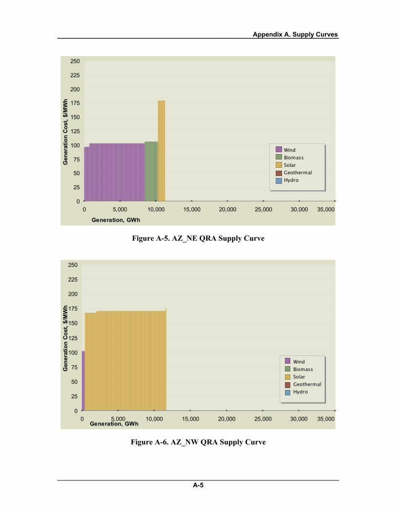
Appendix A. Supply Curves
A-5
0 5,000 10,000 15,000 20,000 25,000 30,000 35,0000
25
50
75
100
125
150
175
200
225
250
Generation, GWh
Gen
erat
ion
Cost
, $/M
Wh
Wind Biomass Solar Geothermal Hydro
Figure A-5. AZ_NE QRA Supply Curve
0 5,000 10,000 15,000 20,000 25,000 30,000 35,0000
25
50
75
100
125
150
175
200
225
250
Generation, GWh
Gen
erat
ion
Cost
, $/M
Wh
WindBiomass SolarGeothermalHydro
Figure A-6. AZ_NW QRA Supply Curve

Appendix A. Supply Curves
A-6
0 5,000 10,000 15,000 20,000 25,000 30,000 35,0000
25
50
75
100
125
150
175
200
225
250
Generation, GWh
Gen
erat
ion
Cost
, $/M
Wh
WindBiomass SolarGeothermalHydro
Figure A-7. AZ_SO QRA Supply Curve
0 5,000 10,000 15,000 20,000 25,000 30,000 35,0000
25
50
75
100
125
150
175
200
225
250
Generation, GWh
Gen
erat
ion
Cost
, $/M
Wh
Wind Biomass Solar Geothermal Hydro
Figure A-8. AZ_WE QRA Supply Curve

Appendix A. Supply Curves
A-7
0 5,000 10,000 15,000 20,000 25,000 30,000 35,0000
25
50
75
100
125
150
175
200
225
250
Generation, GWh
Gen
erat
ion
Cost
, $/M
Wh
WindBiomass SolarGeothermalHydro
Figure A-9. BC_CT QRA Supply Curve Generation costs over $250/MWh not shown on chart.
0 5,000 10,000 15,000 20,000 25,000 30,000 35,0000
25
50
75
100
125
150
175
200
225
250
Generation, GWh
Gen
erat
ion
Cost
, $/M
Wh
Wind Biomass Solar Geothermal Hydro
Figure A-10. BC_EA QRA Supply Curve Generation costs over $250/MWh not shown on chart.
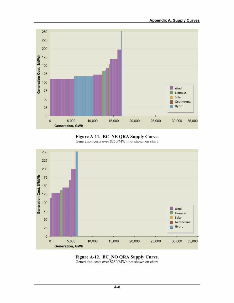
Appendix A. Supply Curves
A-8
0 5,000 10,000 15,000 20,000 25,000 30,000 35,0000
25
50
75
100
125
150
175
200
225
250
Generation, GWh
Gen
erat
ion
Cost
, $/M
Wh
WindBiomass SolarGeothermalHydro
Figure A-11. BC_NE QRA Supply Curve. Generation costs over $250/MWh not shown on chart.
0 5,000 10,000 15,000 20,000 25,000 30,000 35,0000
25
50
75
100
125
150
175
200
225
250
Generation, GWh
Gen
erat
ion
Cost
, $/M
Wh
WindBiomass SolarGeothermalHydro
Figure A-12. BC_NO QRA Supply Curve. Generation costs over $250/MWh not shown on chart.

Appendix A. Supply Curves
A-9
0 5,000 10,000 15,000 20,000 25,000 30,000 35,0000
25
50
75
100
125
150
175
200
225
250
Generation, GWh
Gen
erat
ion
Cost
, $/M
Wh
WindBiomass SolarGeothermalHydro
Figure A-13. BC_NW QRA Supply Curve. Generation costs over $250/MWh not shown on chart.
0 5,000 10,000 15,000 20,000 25,000 30,000 35,0000
25
50
75
100
125
150
175
200
225
250
Generation, GWh
Gen
erat
ion
Cost
, $/M
Wh
WindBiomass SolarGeothermalHydro
Figure A-14. BC_SE QRA Supply Curve. Generation costs over $250/MWh not shown on chart.
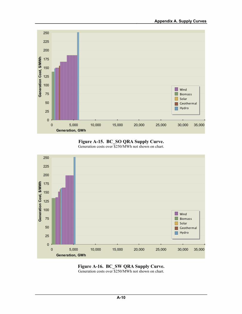
Appendix A. Supply Curves
A-10
0 5,000 10,000 15,000 20,000 25,000 30,000 35,0000
25
50
75
100
125
150
175
200
225
250
Generation, GWh
Gen
erat
ion
Cost
, $/M
Wh
WindBiomass SolarGeothermalHydro
Figure A-15. BC_SO QRA Supply Curve. Generation costs over $250/MWh not shown on chart.
0 5,000 10,000 15,000 20,000 25,000 30,000 35,0000
25
50
75
100
125
150
175
200
225
250
Generation, GWh
Gen
erat
ion
Cost
, $/M
Wh
WindBiomass SolarGeothermalHydro
Figure A-16. BC_SW QRA Supply Curve. Generation costs over $250/MWh not shown on chart.

Appendix A. Supply Curves
A-11
0 5,000 10,000 15,000 20,000 25,000 30,000 35,0000
25
50
75
100
125
150
175
200
225
250
Generation, GWh
Gen
erat
ion
Cost
, $/M
Wh
Wind Biomass Solar Geothermal Hydro
Figure A-17. BC_WC QRA Supply Curve. Generation costs over $250/MWh not shown on chart.
0 5,000 10,000 15,000 20,000 25,000 30,000 35,0000
25
50
75
100
125
150
175
200
225
250
Generation, GWh
Gen
erat
ion
Cost
, $/M
Wh
WindBiomass SolarGeothermalHydro
Figure A-18. BC_WE QRA Supply Curve. Generation costs over $250/MWh not shown on chart.

Appendix A. Supply Curves
A-12
0 5,000 10,000 15,000 20,000 25,000 30,000 35,0000
25
50
75
100
125
150
175
200
225
250
Generation, GWh
Gen
erat
ion
Cost
, $/M
Wh
Wind Biomass Solar Geothermal Hydro
Figure A-19. BJ_NO QRA Supply Curve. Generation costs over $250/MWh not shown on chart.
0 5,000 10,000 15,000 20,000 25,000 30,000 35,0000
25
50
75
100
125
150
175
200
225
250
Generation, GWh
Gen
erat
ion
Cost
, $/M
Wh
Wind Biomass Solar Geothermal Hydro
Figure A-20. BJ_SO QRA Supply Curve. Generation costs over $250/MWh not shown on chart.

Appendix A. Supply Curves
A-13
0 5,000 10,000 15,000 20,000 25,000 30,000 35,0000
25
50
75
100
125
150
175
200
225
250
Generation, GWh
Gen
erat
ion
Cost
, $/M
Wh
WindBiomass SolarGeothermalHydro
Figure A-21. CA_CT QRA Supply Curve.
0 5,000 10,000 15,000 20,000 25,000 30,000 35,0000
25
50
75
100
125
150
175
200
225
250
Generation, GWh
Gen
erat
ion
Cost
, $/M
Wh
WindBiomass SolarGeothermalHydro
Figure A-22. CA_EA QRA Supply Curve.

Appendix A. Supply Curves
A-14
0 5,000 10,000 15,000 20,000 25,000 30,000 35,0000
25
50
75
100
125
150
175
200
225
250
Generation, GWh
Gen
erat
ion
Cost
, $/M
Wh
WindBiomass SolarGeothermalHydro
Figure A-23. CA_NE QRA Supply Curve.
0 5,000 10,000 15,000 20,000 25,000 30,000 35,0000
25
50
75
100
125
150
175
200
225
250
Generation, GWh
Gen
erat
ion
Cost
, $/M
Wh
Wind Biomass Solar Geothermal Hydro
Figure A-24. CA_SO QRA Supply Curve.

Appendix A. Supply Curves
A-15
0 5,000 10,000 15,000 20,000 25,000 30,000 35,0000
25
50
75
100
125
150
175
200
225
250
Generation, GWh
Gen
erat
ion
Cost
, $/M
Wh
Wind Biomass Solar Geothermal Hydro
Figure A-25. CA_WE QRA Supply Curve.
0 5,000 10,000 15,000 20,000 25,000 30,000 35,0000
25
50
75
100
125
150
175
200
225
250
Generation, GWh
Gen
erat
ion
Cost
, $/M
Wh
Wind Biomass Solar Geothermal Hydro
Figure A-26. CO_EA QRA Supply Curve.

Appendix A. Supply Curves
A-16
0 5,000 10,000 15,000 20,000 25,000 30,000 35,0000
25
50
75
100
125
150
175
200
225
250
Generation, GWh
Gen
erat
ion
Cost
, $/M
Wh
Wind Biomass Solar Geothermal Hydro
Figure A-27. CO_NE QRA Supply Curve.
0 5,000 10,000 15,000 20,000 25,000 30,000 35,0000
25
50
75
100
125
150
175
200
225
250
Generation, GWh
Gen
erat
ion
Cost
, $/M
Wh
Wind Biomass Solar Geothermal Hydro
Figure A-28. CO_SE QRA Supply Curve.

Appendix A. Supply Curves
A-17
0 5,000 10,000 15,000 20,000 25,000 30,000 35,0000
25
50
75
100
125
150
175
200
225
250
Generation, GWh
Gen
erat
ion
Cost
, $/M
Wh
Wind Biomass Solar Geothermal Hydro
Figure A-29. CO_SO QRA Supply Curve.
0 5,000 10,000 15,000 20,000 25,000 30,000 35,0000
25
50
75
100
125
150
175
200
225
250
Generation, GWh
Gen
erat
ion
Cost
, $/M
Wh
Wind Biomass Solar Geothermal Hydro
Figure A-30. ID_EA QRA Supply Curve.

Appendix A. Supply Curves
A-18
0 5,000 10,000 15,000 20,000 25,000 30,000 35,0000
25
50
75
100
125
150
175
200
225
250
Generation, GWh
Gen
erat
ion
Cost
, $/M
Wh
Wind Biomass Solar Geothermal Hydro
Figure A-31. ID_SW QRA Supply Curve.
0 5,000 10,000 15,000 20,000 25,000 30,000 35,0000
25
50
75
100
125
150
175
200
225
250
Generation, GWh
Gen
erat
ion
Cost
, $/M
Wh
Wind Biomass Solar Geothermal Hydro
Figure A-32. MT_CT QRA Supply Curve.
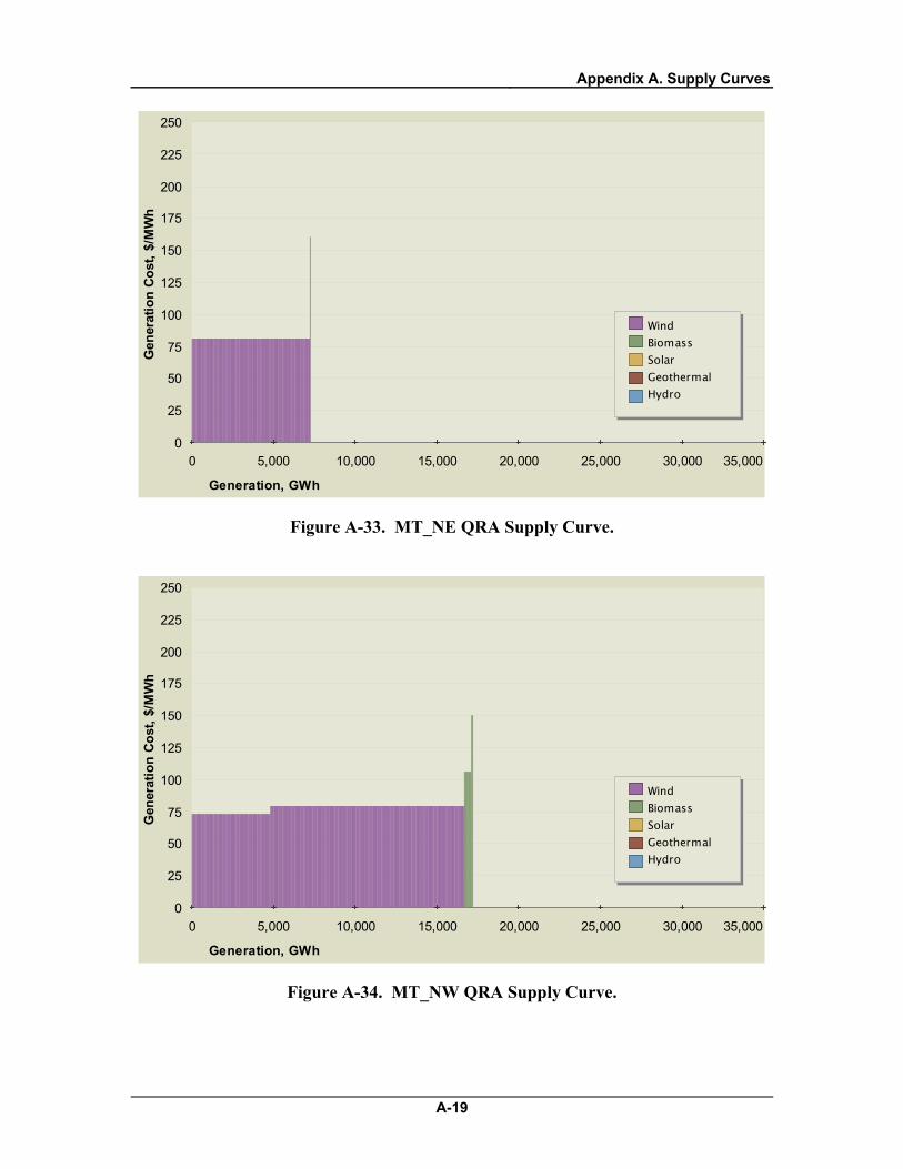
Appendix A. Supply Curves
A-19
0 5,000 10,000 15,000 20,000 25,000 30,000 35,0000
25
50
75
100
125
150
175
200
225
250
Generation, GWh
Gen
erat
ion
Cost
, $/M
Wh
Wind Biomass Solar Geothermal Hydro
Figure A-33. MT_NE QRA Supply Curve.
0 5,000 10,000 15,000 20,000 25,000 30,000 35,0000
25
50
75
100
125
150
175
200
225
250
Generation, GWh
Gen
erat
ion
Cost
, $/M
Wh
Wind Biomass Solar Geothermal Hydro
Figure A-34. MT_NW QRA Supply Curve.

Appendix A. Supply Curves
A-20
0 5,000 10,000 15,000 20,000 25,000 30,000 35,0000
25
50
75
100
125
150
175
200
225
250
Generation, GWh
Gen
erat
ion
Cost
, $/M
Wh
Wind Biomass Solar Geothermal Hydro
Figure A-35. NM_CT QRA Supply Curve.
0 5,000 10,000 15,000 20,000 25,000 30,000 35,0000
25
50
75
100
125
150
175
200
225
250
Generation, GWh
Gen
erat
ion
Cost
, $/M
Wh Wind
Biomass Solar Geothermal Hydro
Figure A-36. NM_EA QRA Supply Curve.

Appendix A. Supply Curves
A-21
0 5,000 10,000 15,000 20,000 25,000 30,000 35,0000
25
50
75
100
125
150
175
200
225
250
Generation, GWh
Gen
erat
ion
Cost
, $/M
Wh
WindBiomass SolarGeothermalHydro
Figure A-37. NM_SE QRA Supply Curve.
0 5,000 10,000 15,000 20,000 25,000 30,000 35,0000
25
50
75
100
125
150
175
200
225
250
Generation, GWh
Gen
erat
ion
Cost
, $/M
Wh
WindBiomass SolarGeothermalHydro
Figure A-38. NM_SO QRA Supply Curve.

Appendix A. Supply Curves
A-22
0 5,000 10,000 15,000 20,000 25,000 30,000 35,0000
25
50
75
100
125
150
175
200
225
250
Generation, GWh
Gen
erat
ion
Cost
, $/M
Wh
Wind Biomass Solar Geothermal Hydro
Figure A-39. NM_SW QRA Supply Curve.
0 5,000 10,000 15,000 20,000 25,000 30,000 35,0000
25
50
75
100
125
150
175
200
225
250
Generation, GWh
Gen
erat
ion
Cost
, $/M
Wh
Wind Biomass Solar Geothermal Hydro
Figure A-40. NV_EA QRA Supply Curve.

Appendix A. Supply Curves
A-23
0 5,000 10,000 15,000 20,000 25,000 30,000 35,0000
25
50
75
100
125
150
175
200
225
250
Generation, GWh
Gen
erat
ion
Cost
, $/M
Wh
Wind Biomass Solar Geothermal Hydro
Figure A-41. NV_NO QRA Supply Curve.
0 5,000 10,000 15,000 20,000 25,000 30,000 35,0000
25
50
75
100
125
150
175
200
225
250
Generation, GWh
Gen
erat
ion
Cost
, $/M
Wh
Wind Biomass Solar Geothermal Hydro
Figure A-42. NV_SW QRA Supply Curve.

Appendix A. Supply Curves
A-24
0 5,000 10,000 15,000 20,000 25,000 30,000 35,0000
25
50
75
100
125
150
175
200
225
250
Generation, GWh
Gen
erat
ion
Cost
, $/M
Wh
Wind Biomass Solar Geothermal Hydro
Figure A-43. NV_WE QRA Supply Curve.
0 5,000 10,000 15,000 20,000 25,000 30,000 35,0000
25
50
75
100
125
150
175
200
225
250
Generation, GWh
Gen
erat
ion
Cost
, $/M
Wh
Wind Biomass Solar Geothermal Hydro
Figure A-44. OR_NE QRA Supply Curve.
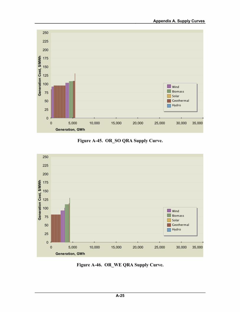
Appendix A. Supply Curves
A-25
0 5,000 10,000 15,000 20,000 25,000 30,000 35,0000
25
50
75
100
125
150
175
200
225
250
Generation, GWh
Gen
erat
ion
Cost
, $/M
Wh
Wind Biomass Solar Geothermal Hydro
Figure A-45. OR_SO QRA Supply Curve.
0 5,000 10,000 15,000 20,000 25,000 30,000 35,0000
25
50
75
100
125
150
175
200
225
250
Generation, GWh
Gen
erat
ion
Cost
, $/M
Wh
Wind Biomass Solar Geothermal Hydro
Figure A-46. OR_WE QRA Supply Curve.

Appendix A. Supply Curves
A-26
0 5,000 10,000 15,000 20,000 25,000 30,000 35,0000
25
50
75
100
125
150
175
200
225
250
Generation, GWh
Gen
erat
ion
Cost
, $/M
Wh
Wind Biomass Solar Geothermal Hydro
Figure A-47. TX QRA Supply Curve.
0 5,000 10,000 15,000 20,000 25,000 30,000 35,0000
25
50
75
100
125
150
175
200
225
250
Generation, GWh
Gen
erat
ion
Cost
, $/M
Wh
Wind Biomass Solar Geothermal Hydro
Figure A-48. UT_WE QRA Supply Curve.

Appendix A. Supply Curves
A-27
0 5,000 10,000 15,000 20,000 25,000 30,000 35,0000
25
50
75
100
125
150
175
200
225
250
Generation, GWh
Gen
erat
ion
Cost
, $/M
Wh
Wind Biomass Solar Geothermal Hydro
Figure A-49. WA_SO QRA Supply Curve.
0 5,000 10,000 15,000 20,000 25,000 30,000 35,0000
25
50
75
100
125
150
175
200
225
250
Generation, GWh
Gen
erat
ion
Cost
, $/M
Wh
Wind Biomass Solar Geothermal Hydro
Figure A-50. WY_EA QRA Supply Curve.
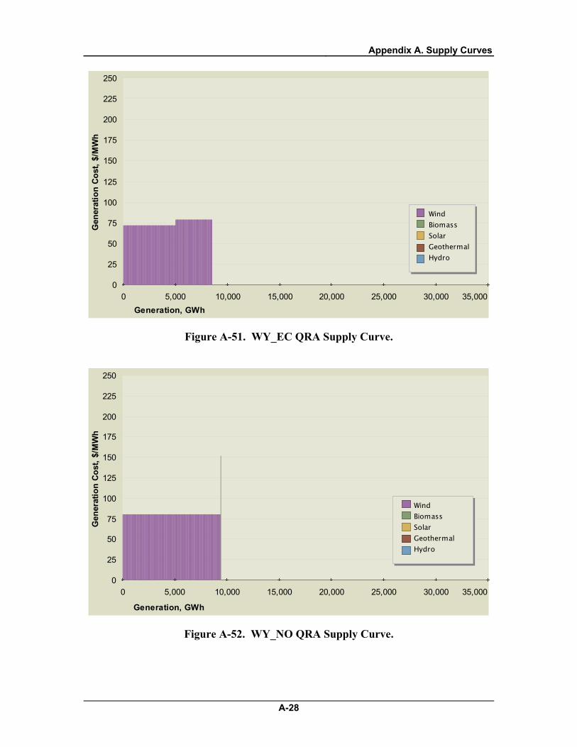
Appendix A. Supply Curves
A-28
0 5,000 10,000 15,000 20,000 25,000 30,000 35,0000
25
50
75
100
125
150
175
200
225
250
Generation, GWh
Gen
erat
ion
Cost
, $/M
Wh
WindBiomass SolarGeothermalHydro
Figure A-51. WY_EC QRA Supply Curve.
0 5,000 10,000 15,000 20,000 25,000 30,000 35,0000
25
50
75
100
125
150
175
200
225
250
Generation, GWh
Gen
erat
ion
Cost
, $/M
Wh
Wind Biomass Solar Geothermal Hydro
Figure A-52. WY_NO QRA Supply Curve.

Appendix A. Supply Curves
A-29
0 5,000 10,000 15,000 20,000 25,000 30,000 35,0000
25
50
75
100
125
150
175
200
225
250
Generation, GWh
Gen
erat
ion
Cost
, $/M
Wh
Wind Biomass Solar Geothermal Hydro
Figure A-53. WY_SO QRA Supply Curve.
Appendix B. QRA Capacity and Energy Summary Tables
B-1
Appendix B. QRA Capacity and Energy Summary Tables
Western Renewable Energy Zones Qualified Resource Area (QRA)
Renewable Energy Resource Summary Tables September 30, 2009
The following two sets of tables quantify the energy generating capacity in megawatts and the theoretical annual energy generation in gigawatt-hours per year for each of the following resources in each QRA: wind, solar, conventional discovered geothermal energy resources, run of river and large impoundment hydropower resources in Canada and incremental hydropower resources for the US. Undiscovered geothermal resources are quantified in each state for which data are available, but are not quantified in the QRA totals. Enhanced geothermal systems and other non-REZ resources are not quantified in these tables.
The first set of tables quantifies QRA capacity and annual energy generation after developability discounts have been applied to wind and solar resources. These are described in further depth in the WREZ Phase 1 QRA Identification Technical Report and in the notes below. The second set of tables quantifies QRA capacity and annual energy generation with no developability discounts applied to wind and solar.
Exclusions Areas that by law or regulation are precluded from renewable energy development have been excluded. For example, renewable energy resources located inside national parks that lie inside QRA boundaries are not quantified here. Areas that fail to meet a number of technical criteria, such as terrain slope, have also been excluded from this analysis. The analysis has taken into account all avoid/exclude areas for which the E&L had data at the time of its completion. It has taken into account the effect of wildlife avoid and high sensitivity areas in three states, which requested that their wildlife avoid areas be excluded from the analysis: Colorado, Idaho, Oregon and Washington.
Developability Discounts In addition to the environmental and land use exclusions mentioned above, various constraints, such as land ownership, the presence of structures, local zoning restrictions or other factors will limit the “developability” of renewable energy resources. For this reason, developability discounts were applied to total resource potential in the US to account for the likelihood that within any area, only a portion of the total resource potential is developable. After all other filters and exclusions have been applied, the remaining wind and solar resource potential are discounted to 25 and 3.5 percent of their total potential respectively. These discounts were not applied to Canadian resources, as the Canadian data had already taken similar factors into account.
These discounts are only applied in the first set of tables. They are not applied in the second set.
B-2

QRA Size Criteria Areas must meet minimum and maximum size criteria in order to be considered QRAs. A QRA must be an area with a radius no greater than 100 miles and contain at least 1,500 MW of wind, solar or large hydropower after all exclusion criteria and developability discounts have been applied. QRAs that are composed largely of geothermal resources can be as small as 500 MW. A different methodology was used to quantify resource potential in Canada, so Canadian QRAs can be less than 1,500 MW.
QRA Labels QRAs are labeled based on their state and the region of the state in which the majority of their area is located. Many QRAs overlap state boundaries. As a result, the totals for each state in the table below do not correspond exactly with the total MW quantified in that state in QRAs in the WREZ process. NOTES: a In the US, only the best classes of wind and solar resources in each state are quantified. In each
state, only wind resources of that state’s minimum wind power class and higher and solar resources of that state’s minimum direct normal insolation level and higher are quantified. In Canada, renewable energy resources were quantified using a different methodology, which assessed resources on the site level, rather than using raw resource data so “best in state” criteria were not applied and Canadian resources were not discounted. For more information, please visit the public comment package Zone Identification and Technology Analysis working group web page.
b Undiscovered geothermal resources are believed to exist in certain areas because of the
presence of geologic systems that have been correlated with geothermal resource potential in other areas. This undiscovered potential has not yet been quantified at specific locations where a geothermal plant could be built, but it can be estimated on the state level at different confidence intervals. As a result, these resources are not quantified at the QRA level or included in the economic modeling of QRAs. When undiscovered geothermal potential is believed to exist in a QRA, it will be noted even though it will not be quantified. The mean estimated potential from these resources by state is quantified in this table by state/province. It is not captured in the QRA MW total, because these resources are not being quantified at the QRA level. US estimates are from the USGS, and Canadian estimates are from CanGEA.
c Data on undiscovered geothermal resources were not available for Baja California Norte and Texas. d Small and large hydropower was quantified in Canada. Incremental additions to powered or
non-powered dams were quantified in the US.
e These resources may exist, but they were not quantified in this study.
f As noted above, a different resource assessment methodology was used to quantify the MW of renewable energy resources available in Canada. Data on the wind power class in British Columbia and Alberta were not available from this assessment. As a result, only the total MW
B-3
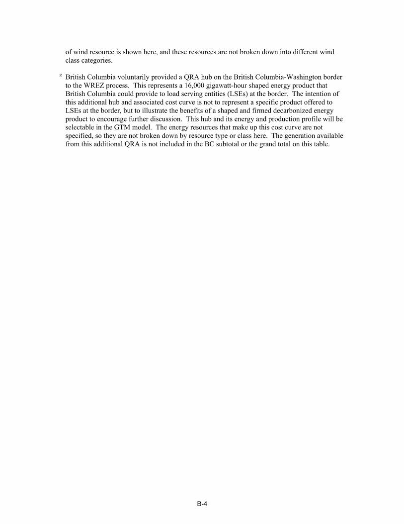
of wind resource is shown here, and these resources are not broken down into different wind class categories.
g British Columbia voluntarily provided a QRA hub on the British Columbia-Washington border to the WREZ process. This represents a 16,000 gigawatt-hour shaped energy product that British Columbia could provide to load serving entities (LSEs) at the border. The intention of this additional hub and associated cost curve is not to represent a specific product offered to LSEs at the border, but to illustrate the benefits of a shaped and firmed decarbonized energy product to encourage further discussion. This hub and its energy and production profile will be selectable in the GTM model. The energy resources that make up this cost curve are not specified, so they are not broken down by resource type or class here. The generation available from this additional QRA is not included in the BC subtotal or the grand total on this table.
B-4

Western Renewable Energy Zones Qualified Resource Area (QRA)Renewable Energy Generating Capacity Summary
September 30, 2009
QRA state/ prov
QRA Name Solar thermal MW by DNI level (kWh/sqmtr/day)a Wind MW by wind power classa Geothermal MW
Hydro MWd
Biomass MW Total MW
6.5 - 6.75
6.75 - 7.0 7.0 - 7.25 7.25 - 7.5 7.5 + SOLAR
TOTAL 3 4 5 + WIND TOTAL
Discov-ered
Undis-coveredb,c REZ-only
AZ AZ_NE e e e 309 0 309 3,305 137 57 3,499 0 e 0 256 4,064AZ AZ_NW e e 36 2,841 648 3,525 209 7 2 217 0 e 0 17 3,760AZ AZ_SO e e e 6,623 0 6,623 e e e e 0 e 0 8 6,631AZ AZ_WE e e e 7,766 1,556 9,322 e e e e 0 e 0 47 9,369AZ Total 0 0 36 17,539 2,204 19,780 3,514 144 59 3,717 0 1,043 0 327 23,824CA CA_CT e e 500 891 868 2,259 1,162 207 41 1,410 0 e 0 11 3,680CA CA_EA e e 1,035 1,575 69 2,679 213 20 5 237 0 e 0 11 2,927CA CA_NE e e 1,213 2,862 602 4,676 489 74 2 565 0 e 0 0 5,241CA CA_SO e e 2,977 392 36 3,405 477 139 129 744 1,434 e 2 19 5,604CA CA_WE e e 508 1,331 1,212 3,050 1,261 825 1,000 3,085 0 e 0 106 6,241CA Total 0 0 6,232 7,051 2,786 16,069 3,602 1,264 1,176 6,042 1,434 11,340 2 147 23,693CO CO_EA e e 0 0 0 0 e 2,445 0 2,445 0 e 0 7 2,452CO CO_NE e e 0 0 0 0 e 4,016 203 4,218 0 e 0 13 4,231CO CO_SE e e 0 0 0 0 e 8,777 36 8,813 0 e 0 16 8,829CO CO_SO e e 2,151 152 0 2,303 e 112 92 203 0 e 0 118 2,624CO Total 0 0 2,151 152 0 2,303 0 15,350 330 15,679 0 1,105 0 153 18,135ID ID_EA e e e e e 0 618 67 12 696 201 e 0 260 1,157ID ID_SW e e e e e 0 893 13 1 907 128 e 8 98 1,141ID Total 0 0 0 0 0 0 1,510 80 13 1,603 329 1,872 8 358 2,299MT MT_CT e e e e e 0 e e 2,527 2,527 0 e 0 77 2,604MT MT_NE e e e e e 0 e e 2,337 2,337 0 e 0 4 2,341MT MT_NW e e e e e 0 e e 5,194 5,194 0 e 0 66 5,261MT Total 0 0 0 0 0 0 0 0 10,059 10,059 0 771 0 147 10,206NM NM_CT e e 2,679 459 0 3,138 e e e e 0 e 0 110 3,249NM NM_EA e e 83 0 0 83 e 9,857 1,433 11,290 0 e 0 44 11,418NM NM_SE e e 0 0 0 0 e 1,338 557 1,894 0 e 0 22 1,916NM NM_SO e e 3,128 1,219 0 4,347 e e e e 0 e 0 12 4,359NM NM_SW e e 1,784 4,365 0 6,149 e e e e 0 e 0 34 6,183NM Total 0 0 7,675 6,042 0 13,718 0 11,195 1,989 13,184 0 1,484 0 223 27,124
CAPACITY (MW)B-5

Western Renewable Energy Zones Qualified Resource Area (QRA)Renewable Energy Generating Capacity Summary
September 30, 2009
QRA state/ prov
QRA Name Solar thermal MW by DNI level (kWh/sqmtr/day)a Wind MW by wind power classa Geothermal MW
Hydro MWd
Biomass MW Total MW
6.5 - 6.75
6.75 - 7.0 7.0 - 7.25 7.25 - 7.5 7.5 + SOLAR
TOTAL 3 4 5 + WIND TOTAL
Discov-ered
Undis-coveredb,c REZ-only
NV NV_EA e e 4,079 3,305 428 7,812 e e e e 24 e 0 134 7,970NV NV_NO e e e e e e e e e e 1,088 e 2 133 1,223NV NV_SW e e 369 1,212 1,895 3,475 212 16 6 233 0 e 0 12 3,720NV NV_WE e e 2,142 4,207 946 7,294 160 27 12 198 296 e 0 22 7,810NV Total 0 0 6,590 8,724 3,268 18,582 371 42 18 431 1,408 4,364 2 300 20,723OR OR_NE e e e e e e 1,476 464 104 2,043 0 e 0 388 2,431OR OR_SO e e e e e e 388 69 54 511 501 e 0 118 1,130OR OR_WE e e e e e e 196 90 57 343 331 e 3 140 817OR Total 0 0 0 0 0 0 2,059 623 215 2,897 832 1,893 3 646 4,378TX TX 461 3,809 7 0 0 4,277 208 235 64 507 0 e 0 3 4,787TX Total 461 3,809 7 0 0 4,277 208 235 64 507 0 0 0 3 4,787UT UT_WE 4,786 2,178 237 0 0 7,202 1,516 133 29 1,678 375 e 0 91 9,346UT Total 4,786 2,178 237 0 0 7,202 1,516 133 29 1,678 375 1,464 0 91 9,346WA WA_SO e e e e e 0 2,566 602 92 3,260 0 e 544 101 3,905WA Total 0 0 0 0 0 0 2,566 602 92 3,260 0 300 544 101 3,905WY WY_EA e e e e e 0 e e 7,257 7,257 0 e 0 5 7,262WY WY_EC e e e e e 0 e e 2,594 2,594 0 e 0 0 2,594WY WY_NO e e e e e 0 e e 3,063 3,063 0 e 0 5 3,069WY WY_SO e e e e e 0 e 615 1,324 1,939 0 e 0 6 1,945WY Total 0 0 0 0 0 0 0 615 14,239 14,854 0 174 0 16 14,869AB AB_EA e e e e e 0 f f f 1,319 0 e 0 96 1,415AB AB_EC e e e e e 0 f f f 700 0 e 0 122 822AB AB_NO e e e e e 0 f f f 0 0 e 1,800 0 1,800AB AB_SE e e e e e 0 f f f 2,410 0 e 0 51 2,461AB Total 0 0 0 0 0 0 0 0 0 4,429 0 0 1,800 268 6,497BC BC_CT e e e e e 0 f f f 902 0 e 4 122 1,027BC BC_EA e e e e e 0 f f f 0 32 e 1,076 34 1,142BC BC_NE e e e e e 0 f f f 4,081 16 e 1,006 109 5,212BC BC_NO e e e e e 0 f f f 2,176 0 e 87 79 2,342
CAPACITY (MW)B-6

Western Renewable Energy Zones Qualified Resource Area (QRA)Renewable Energy Generating Capacity Summary
September 30, 2009
QRA state/ prov
QRA Name Solar thermal MW by DNI level (kWh/sqmtr/day)a Wind MW by wind power classa Geothermal MW
Hydro MWd
Biomass MW Total MW
6.5 - 6.75
6.75 - 7.0 7.0 - 7.25 7.25 - 7.5 7.5 + SOLAR
TOTAL 3 4 5 + WIND TOTAL
Discov-ered
Undis-coveredb,c REZ-only
BC BC_NW e e e e e 0 f f f 1,285 32 e 572 85 1,974BC BC_SE e e e e e 0 f f f 138 32 e 165 60 396BC BC_SHP g g g g g g g g g g g g g g 3,000g
BC BC_SO e e e e e 0 f f f 2,300 32 e 196 109 2,638BC BC_SW e e e e e 0 f f f 1,744 16 e 198 162 2,119BC BC_WC e e e e e 0 f f f 0 180 e 2,737 127 3,044BC BC_WE e e e e e 0 f f f 1,318 0 e 50 53 1,421BC Total 0 0 0 0 0 0 0 0 0 13,943 340 0 6,092 939 21,315BJ BJ_NO e e 3,015 952 13 3,980 e 758 925 1,684 0 e e e 5,664BJ BJ_SO e e 439 523 50 1,012 e 614 639 1,253 0 e e e 2,264BJ Total 0 0 3,454 1,475 63 4,991 0 1,372 1,564 2,937 0 0 0 0 7,928Grand Total 5,247 5,988 26,382 40,982 8,322 86,921 15,347 31,654 29,846 95,219 4,718 25,810 8,452 3,720 199,029
CAPACITY (MW)B-7

Western Renewable Energy Zones Qualified Resource Area (QRA)Renewable Energy Generation Summary
September 30, 2009
QRA state/ prov
QRA Name Solar thermal GWh/yr by DNI level (kWh/sqmtr/day)a Wind GWh/yr by wind power classa Geothermal GWh/yr
Hydro GWh/yrd
Biomass GWh/yr Total GWh/yr
6.5 - 6.75 6.75 - 7.0 7.0 - 7.25 7.25 - 7.5 7.5 + SOLAR TOTAL 3 4 5 + WIND
TOTALDiscov-
eredUndis-
coveredb,c REZ-onlyAZ AZ_NE e e e 696 0 696 8,107 371 182 8,661 0 e 0 1,903 11,260AZ AZ_NW e e 84 6,595 1,505 8,184 512 19 5 536 0 e 0 127 8,847AZ AZ_SO e e e 15,607 0 15,607 e e e e 0 e 0 59 15,665AZ AZ_WE e e e 18,912 3,790 22,702 e e e e 0 e 0 350 23,051AZ Total 0 0 84.3247 41,809 5,295 47,188 8,619 390 188 9,197 0 7,309 0 2,438 58,824CA CA_CT e e 1,191 2,123 2,069 5,383 2,850 561 134 3,545 0 e 0 83 9,011CA CA_EA e e 2,375 3,615 158 6,148 522 53 14 589 0 e 0 83 6,821CA CA_NE e e 2,836 6,693 1,407 10,937 1,199 202 7 1,407 0 e 0 12,344CA CA_SO e e 6,937 915 83 7,934 1,170 376 429 1,976 11,074 e 8 142 21,134CA CA_WE e e 1,139 2,984 2,717 6,840 3,093 2,239 3,282 8,615 0 e 0 786 16,241CA Total 0 0 14,477 16,330 6,434 37,241 8,834 3,432 3,867 16,132 11,074 79,471 8 1,095 65,550CO CO_EA e e 0 0 0 0 e 6,640 0 6,640 0 e 0 50 6,689CO CO_NE e e 0 0 0 0 e 10,904 623 11,527 0 e 0 94 11,621CO CO_SE e e 0 0 0 0 e 23,836 109 23,944 0 e 0 120 24,065CO CO_SO e e 4,617 326 0 4,943 e 303 299 602 0 e 0 875 6,421CO Total 0 0 4,617 326 0 4,943 0 41,683 1,031 42,714 0 7,744 0 1,139 48,796ID ID_EA e e e e e 0 1,515 182 38 1,735 1,448 e 0 1,936 5,119ID ID_SW e e e e e 0 2,189 36 4 2,229 897 e 728 3,854ID Total 0 0 0 0 0 0 3,705 217 43 3,965 2,345 13,119 0 2,663 8,973MT MT_CT e e e e e 0 e e 8,224 8,224 0 e 0 570 8,794MT MT_NE e e e e e 0 e e 7,429 7,429 0 e 0 32 7,461MT MT_NW e e e e e 0 e e 16,932 16,932 0 e 0 494 17,427MT Total 0 0 0 0 0 0 0 0 32,585 32,585 0 5,403 0 1,097 33,682NM NM_CT e e 6,126 1,049 0 7,175 e e e e 0 e 0 823 7,998NM NM_EA e e 183 0 0 183 e 26,768 4,427 31,196 0 e 0 330 31,708NM NM_SE e e 0 0 0 0 e 3,632 1,748 5,381 0 e 0 162 5,542NM NM_SO e e 7,317 2,850 0 10,167 e e e e 0 e 0 92 10,258NM NM_SW e e 4,298 10,515 0 14,814 e e e e 0 e 0 254 15,067
ENERGY (GWh/yr)B-8

Western Renewable Energy Zones Qualified Resource Area (QRA)Renewable Energy Generation Summary
September 30, 2009
QRA state/ prov
QRA Name Solar thermal GWh/yr by DNI level (kWh/sqmtr/day)a Wind GWh/yr by wind power classa Geothermal GWh/yr
Hydro GWh/yrd
Biomass GWh/yr Total GWh/yr
6.5 - 6.75 6.75 - 7.0 7.0 - 7.25 7.25 - 7.5 7.5 + SOLAR TOTAL 3 4 5 + WIND
TOTALDiscov-
eredUndis-
coveredb,c REZ-onlyNM Total 0 0 17,924 14,414 0 32,338 0 30,400 6,176 36,576 0 10,400 0 1,659 70,573NV NV_EA e e 9,076 7,354 952 17,382 e e e e 168 e 0 995 18,546NV NV_NO e e e e e e e e e e 7,799 e 9 991 8,799NV NV_SW e e 840 2,760 4,316 7,916 520 42 19 581 0 e 0 88 8,584NV NV_WE e e 4,916 9,655 2,170 16,741 391 73 39 503 2,074 e 0 161 19,479NV Total 0 0 14,832 19,769 7,438 42,039 911 115 58 1,083 10,041 30,583 9 2,235 55,408OR OR_NE e e e e e e 3,619 1,259 325 5,204 0 e 0 2,892 8,095OR OR_SO e e e e e e 951 188 181 1,320 3,550 e 0 876 5,747OR OR_WE e e e e e e 481 244 191 916 2,596 e 16 1,040 4,567OR Total 0 0 0 0 0 0 5,051 1,691 698 7,439 6,146 13,266 16 4,808 18,409TX TX 1,001 8,275 15 0 0 9,291 510 639 197 1,346 0 e 0 26 10,663TX Total 1,001 8,275 15 0 0 9,291 510 639 197 1,346 0 0 0 26 10,663UT UT_WE 10,147 4,618 503 0 0 15,268 3,718 361 95 4,174 2,702 e 0 674 22,818UT Total 10,147 4,618 503 0 0 15,268 3,718 361 95 4,174 2,702 10,260 0 674 22,818WA WA_SO e e e e e 0 6,295 1,635 295 8,225 0 e 2,531 754 11,509WA Total 0 0 0 0 0 0 6,295 1,635 295 8,225 0 2,102 2,531 754 11,509WY WY_EA e e e e e 0 e e 24,570 24,570 0 e 0 35 24,605WY WY_EC e e e e e 0 e e 8,801 8,801 0 e 0 0 8,801WY WY_NO e e e e e 0 e e 9,606 9,606 0 e 0 41 9,647WY WY_SO e e e e e 0 e 1,670 4,457 6,126 0 e 0 41 6,168WY Total 0 0 0 0 0 0 0 1,670 47,434 49,104 0 1,219 0 117 49,221AB AB_EA e e e e e 0 f f f 4,044 0 e 0 713 4,757AB AB_EC e e e e e 0 f f f 2,146 0 e 0 907 3,053AB AB_NO e e e e e 0 f f f 0 0 e 6,307 1 6,308AB AB_SE e e e e e 0 f f f 7,389 0 e 0 376 7,765AB Total 0 0 0 0 0 0 0 0 0 13,579 0 0 6,307 1,997 21,883BC BC_CT e e e e e 0 f f f 1,953 0 e 10 905 2,868BC BC_EA e e e e e 0 f f f 0 224 e 437 250 911
ENERGY (GWh/yr)B-9

Western Renewable Energy Zones Qualified Resource Area (QRA)Renewable Energy Generation Summary
September 30, 2009
QRA state/ prov
QRA Name Solar thermal GWh/yr by DNI level (kWh/sqmtr/day)a Wind GWh/yr by wind power classa Geothermal GWh/yr
Hydro GWh/yrd
Biomass GWh/yr Total GWh/yr
6.5 - 6.75 6.75 - 7.0 7.0 - 7.25 7.25 - 7.5 7.5 + SOLAR TOTAL 3 4 5 + WIND
TOTALDiscov-
eredUndis-
coveredb,c REZ-onlyBC BC_NE e e e e e 0 f f f 11,389 112 e 4,953 811 17,265BC BC_NO e e e e e 0 f f f 5,730 0 e 420 588 6,738BC BC_NW e e e e e 0 f f f 3,159 224 e 1,984 632 5,999BC BC_SE e e e e e 0 f f f 252 224 e 508 447 1,432BC BC_SHPD g g g g g g g g g g g g g g 15,797g
BC BC_SO e e e e e 0 f f f 4,786 224 e 630 815 6,455BC BC_SW e e e e e 0 f f f 3,630 112 e 717 1,204 5,663BC BC_WC e e e e e 0 f f f 0 1,419 e 12,546 949 14,914BC BC_WE e e e e e 0 f f f 3,205 0 e 167 393 3,766BC Total 0 0 0 0 0 0 0 0 0 34,104 2,540 0 22,372 6,994 66,010BJ BJ_NO e e 7,026 2,218 30 9,274 e 2,058 3,110 5,169 0 e e e 14,443BJ BJ_SO e e 1,022 1,218 117 2,357 e 1,668 2,078 3,745 0 e e e 6,102BJ Total 0 0 8,048 3,436 146 11,631 0 3,726 5,188 8,915 0 0 0 0 20,545Grand Total 11,147 12,893 60,500 96,085 19,313 199,939 37,642 85,959 97,853 269,138 34,849 180,876 31,243 27,698 562,867
ENERGY (GWh/yr)B-10
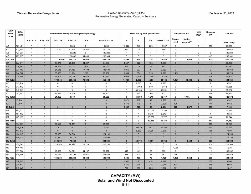
Western Renewable Energy Zones Qualified Resource Area (QRA)Renewable Energy Generating Capacity Summary
September 30, 2009
QRA state/ prov
QRA Name Solar thermal MW by DNI level (kWh/sqmtr/day)a Wind MW by wind power classa Geothermal MW
Hydro MWd
Biomass MW Total MW
6.5 - 6.75 6.75 - 7.0 7.0 - 7.25 7.25 - 7.5 7.5 + SOLAR TOTAL 3 4 5 + WIND TOTAL Discov-ered
Undis-coveredb,c
WREZ-only
AZ AZ_NE e e e 8,836 0 8,836 13,222 546 229 13,997 0 e 0 256 23,088
AZ AZ_NW e e 1,038 81,166 18,522 100,726 835 28 7 869 0 e 0 17 101,612
AZ AZ_SO e e e 189,226 0 189,226 e e e 0 0 e 0 8 189,234
AZ AZ_WE e e e 221,882 44,463 266,344 e e e 0 0 e 0 47 266,391
AZ Total 0 0 1,038 501,110 62,985 565,132 14,056 574 236 14,866 0 1,043 0 327 580,326CA CA_CT e e 14,277 25,463 24,807 64,546 4,647 827 165 5,639 0 e 0 11 70,196
CA CA_EA e e 29,562 45,005 1,966 76,533 851 79 18 947 0 e 0 11 77,491
CA CA_NE e e 34,648 81,759 17,193 133,599 1,955 297 9 2,260 0 e 0 0 135,860
CA CA_SO e e 85,053 11,214 1,015 97,282 1,909 554 515 2,978 1,434 e 2 19 101,714
CA CA_WE e e 14,507 38,018 34,618 87,143 5,045 3,298 3,999 12,342 0 e 0 106 99,590
CA Total 0 0 178,046 201,458 79,598 459,103 14,406 5,055 4,705 24,166 1,434 11,340 2 147 484,851CO CO_EA e e 0 0 0 0 e 9,780 0 9,780 0 e 0 7 9,787
CO CO_NE e e 0 0 0 0 e 16,062 810 16,872 0 e 0 13 16,885
CO CO_SE e e 0 0 0 0 e 35,109 142 35,251 0 e 0 16 35,267
CO CO_SO e e 61,462 4,340 0 65,802 e 447 366 813 0 e 0 118 66,732
CO Total 0 0 61,462 4,340 0 65,802 0 61,398 1,319 62,717 0 1,105 0 153 128,672ID ID_EA e e e e e 0 2,471 267 47 2,786 201 e 0 260 3,247
ID ID_SW e e e e e 0 3,570 52 5 3,628 128 e 8 98 3,862
ID Total 0 0 0 0 0 0 6,042 320 52 6,414 329 1,872 8 358 7,109MT MT_CT e e e e e 0 e e 10,109 10,109 0 e 0 77 10,185
MT MT_NE e e e e e 0 e e 9,349 9,349 0 e 0 4 9,353
MT MT_NW e e e e e 0 e e 20,777 20,777 0 e 0 66 20,844
MT Total 0 0 0 0 0 0 0 0 40,235 40,235 0 771 0 147 40,382NM NM_CT e e 76,554 13,111 0 89,665 e e e 0 0 e 0 110 89,775
NM NM_EA e e 2,382 0 0 2,382 e 39,429 5,731 45,160 0 e 0 44 47,586
NM NM_SE e e 0 0 0 0 e 5,350 2,226 7,576 0 e 0 22 7,598
NM NM_SO e e 89,376 34,814 0 124,191 e e e 0 0 e 0 12 124,203
NM NM_SW e e 50,980 124,714 0 175,694 e e e 0 0 e 0 34 175,728
NM Total 0 0 219,292 172,639 0 391,931 0 44,779 7,957 52,736 0 1,484 0 223 444,890NV NV_EA e e 116,549 94,428 12,229 223,205 e e e 0 24 e 0 134 223,363
NV NV_NO e e e e e 0 e e e 0 1,088 e 2 133 1,223
NV NV_SW e e 10,539 34,621 54,137 99,297 847 62 23 933 0 e 0 12 100,242
NV NV_WE e e 61,195 120,194 27,017 208,405 638 107 47 792 296 e 0 22 209,515
NV Total 0 0 188,283 249,243 93,382 530,908 1,485 169 70 1,725 1,408 4,364 2 300 534,343OR OR_NE e e e e e e 5,902 1,855 414 8,172 0 e 0 388 8,560
OR OR_SO e e e e e e 1,551 276 216 2,044 501 e 0 118 2,662
OR OR_WE e e e e e e 784 359 230 1,372 331 e 3 140 1,847
CAPACITY (MW)Solar and Wind Not Discounted
B-11

Western Renewable Energy Zones Qualified Resource Area (QRA)Renewable Energy Generating Capacity Summary
September 30, 2009
QRA state/ prov
QRA Name Solar thermal MW by DNI level (kWh/sqmtr/day)a Wind MW by wind power classa Geothermal MW
Hydro MWd
Biomass MW Total MW
6.5 - 6.75 6.75 - 7.0 7.0 - 7.25 7.25 - 7.5 7.5 + SOLAR TOTAL 3 4 5 + WIND TOTAL Discov-ered
Undis-coveredb,c
WREZ-only
OR Total 0 0 0 0 0 0 8,237 2,490 860 11,588 832 1,893 3 646 13,069TX TX 13,162 108,834 196 0 0 122,192 832 942 255 2,029 0 e 0 3 124,224
TX Total 13,162 108,834 196 0 0 122,192 832 942 255 2,029 0 0 0 3 124,224UT UT_WE 136,753 62,240 6,783 0 0 205,776 6,063 532 117 6,712 375 e 0 91 212,954
UT Total 136,753 62,240 6,783 0 0 205,776 6,063 532 117 6,712 375 1,464 0 91 212,954WA WA_SO e e e e e 0 10,266 2,408 367 13,040 0 e 544 101 13,685
WA Total 0 0 0 0 0 0 10,266 2,408 367 13,040 0 300 544 101 13,685WY WY_EA e e e e e 0 e e 29,028 29,028 0 e 0 5 29,033
WY WY_EC e e e e e 0 e e 10,376 10,376 0 e 0 0 10,376
WY WY_NO e e e e e 0 e e 12,253 12,253 0 e 0 5 12,258
WY WY_SO e e e e e 0 e 2,459 5,298 7,757 0 e 0 6 7,763
WY Total 0 0 0 0 0 0 0 2,459 56,955 59,415 0 174 0 16 59,430AB AB_EA e e e e e 0 f f f 1,319 0 e 0 96 1,415
AB AB_EC e e e e e 0 f f f 700 0 e 0 122 822
AB AB_NO e e e e e 0 f f f 0 0 e 1,800 0 1,800
AB AB_SE e e e e e 0 f f f 2,410 0 e 0 51 2,461
AB Total 0 0 0 0 0 0 0 0 0 4,429 0 0 1,800 268 6,497BC BC_CT e e e e e 0 f f f 902 0 e 4 122 1,027
BC BC_EA e e e e e 0 f f f 0 32 e 1,076 34 1,142
BC BC_NE e e e e e 0 f f f 4,081 16 e 1,006 109 5,212
BC BC_NO e e e e e 0 f f f 2,176 0 e 87 79 2,342
BC BC_NW e e e e e 0 f f f 1,285 32 e 572 85 1,974
BC BC_SE e e e e e 0 f f f 138 32 e 165 60 396
BC BC_SHPD g g g g g g g g g g g g g g 3,000g
BC BC_SO e e e e e 0 f f f 2,300 32 e 196 109 2,638
BC BC_SW e e e e e 0 f f f 1,744 16 e 198 162 2,119
BC BC_WC e e e e e 0 f f f 0 180 e 2,737 127 3,044
BC BC_WE e e e e e 0 f f f 1,318 0 e 50 53 1,421
BC Total 0 0 0 0 0 0 0 0 0 13,943 340 0 6,092 939 21,315BJ BJ_NO e e 86,153 27,193 363 113,709 e 3,032 3,702 6,734 0 e e e 120,442
BJ BJ_SO e e 12,531 14,939 1,432 28,902 e 2,456 2,555 5,011 0 e e e 33,914
BJ Total 0 0 98,684 42,132 1,795 142,611 0 5,488 6,257 11,745 0 0 0 0 154,356Grand Total 149,915 171,075 753,784 1,170,922 237,760 2,483,456 245,546 506,460 477,538 325,758 4,718 25,810 8,452 3,720 2,826,103
CAPACITY (MW)Solar and Wind Not Discounted
B-12

Western Renewable Energy Zones Qualified Resource Area (QRA)Renewable Energy Generation Summary
September 30, 2009
QRA state/ prov
QRA Name Solar thermal GWh/yr by DNI level (kWh/sqmtr/day)a Wind GWh/yr by wind power classa Geothermal GWh/yr
Hydro GWh/yrd
Biomass GWh/yr Total GWh/yr
6.5 - 6.75 6.75 - 7.0 7.0 - 7.25 7.25 - 7.5 7.5 + SOLAR TOTAL 3 4 5 + WIND TOTAL Discov-ered
Undis-coveredb,c WREZ-only
AZ AZ_NE e e e 19,892 0 19,892 32,430 1,484 729 34,643 0 e 0 1,903 56,439
AZ AZ_NW e e 2,409 188,418 42,998 233,825 2,047 75 22 2,144 0 e 0 127 236,096
AZ AZ_SO e e e 445,901 0 445,901 e e e e 0 e 0 59 445,960
AZ AZ_WE e e e 540,344 108,279 648,623 e e e e 0 e 0 350 648,973
AZ Total 0 0 2,409 1,194,555 151,276 1,348,241 34,477 1,559 751 36,788 0 7,309 0 2,438 1,387,467CA CA_CT e e 34,017 60,671 59,107 153,796 11,399 2,245 535 14,179 0 e 0 83 168,058
CA CA_EA e e 67,848 103,291 4,512 175,651 2,086 214 57 2,358 0 e 0 83 178,093
CA CA_NE e e 81,038 191,228 40,212 312,478 4,794 807 28 5,629 0 e 0 318,106
CA CA_SO e e 198,188 26,131 2,364 226,683 4,682 1,504 1,718 7,904 11,074 e 8 142 245,811
CA CA_WE e e 32,532 85,257 77,634 195,423 12,374 8,957 13,130 34,461 0 e 0 786 230,670
CA Total 0 0 413,624 466,577 183,830 1,064,031 35,335 13,727 15,467 64,530 11,074 79,471 8 1,095 1,140,737CO CO_EA e e 0 0 0 0 e 26,560 0 26,560 0 e 0 50 26,609
CO CO_NE e e 0 0 0 0 e 43,618 2,491 46,109 0 e 0 94 46,203
CO CO_SE e e 0 0 0 0 e 95,343 435 95,778 0 e 0 120 95,898
CO CO_SO e e 131,910 9,314 0 141,224 e 1,213 1,196 2,410 0 e 0 875 144,509
CO Total 0 0 131,910 9,314 0 141,224 0 166,733 4,123 170,857 0 7,744 0 1,139 313,220ID ID_EA e e e e e 0 6,062 726 154 6,942 1,448 e 0 1,936 10,325
ID ID_SW e e e e e 0 8,757 142 17 8,917 897 e 728 10,541
ID Total 0 0 0 0 0 0 14,819 868 171 15,858 2,345 13,119 0 2,663 20,867MT MT_CT e e e e e 0 e e 32,894 32,894 0 e 0 570 33,465
MT MT_NE e e e e e 0 e e 29,715 29,715 0 e 0 32 29,747
MT MT_NW e e e e e 0 e e 67,729 67,729 0 e 0 494 68,223
MT Total 0 0 0 0 0 0 0 0 130,338 130,338 0 5,403 0 1,097 131,435NM NM_CT e e 175,030 29,976 0 205,006 e e e e 0 e 0 823 205,829
NM NM_EA e e 5,216 0 0 5,216 e 107,072 17,710 124,782 0 e 0 330 130,328
NM NM_SE e e 0 0 0 0 e 14,528 6,994 21,522 0 e 0 162 21,684
NM NM_SO e e 209,043 81,428 0 290,472 e e e e 0 e 0 92 290,563
NM NM_SW e e 122,811 300,436 0 423,247 e e e e 0 e 0 254 423,501
NM Total 0 0 512,100 411,840 0 923,941 0 121,601 24,704 146,304 0 10,400 0 1,659 1,071,904NV NV_EA e e 259,326 210,106 27,210 496,641 e e e e 168 e 0 995 497,804
NV NV_NO e e e e e e e e e e 7,799 e 9 991 8,799
NV NV_SW e e 24,004 78,854 123,302 226,160 2,079 168 75 2,322 0 e 0 88 228,570
NV NV_WE e e 140,450 275,859 62,007 478,315 1,565 291 156 2,012 2,074 e 0 161 482,561
NV Total 0 0 423,779 564,818 212,518 1,201,115 3,643 459 231 4,334 10,041 30,583 9 2,235 1,217,735OR OR_NE e e e e e e 14,477 5,037 1,300 20,814 0 e 0 2,892 23,706
OR OR_SO e e e e e e 3,804 751 725 5,280 3,550 e 0 876 9,706
OR OR_WE e e e e e e 1,922 975 766 3,663 2,596 e 16 1,040 7,315
ENERGY (GWh/yr)Solar and Wind Not Discounted
B-13

Western Renewable Energy Zones Qualified Resource Area (QRA)Renewable Energy Generation Summary
September 30, 2009
QRA state/ prov
QRA Name Solar thermal GWh/yr by DNI level (kWh/sqmtr/day)a Wind GWh/yr by wind power classa Geothermal GWh/yr
Hydro GWh/yrd
Biomass GWh/yr Total GWh/yr
6.5 - 6.75 6.75 - 7.0 7.0 - 7.25 7.25 - 7.5 7.5 + SOLAR TOTAL 3 4 5 + WIND TOTAL Discov-ered
Undis-coveredb,c WREZ-only
OR Total 0 0 0 0 0 0 20,203 6,763 2,791 29,757 6,146 13,266 16 4,808 40,727TX TX 28,593 236,440 426 0 0 265,460 2,041 2,558 786 5,385 0 e 0 26 270,871
TX Total 28,593 236,440 426 0 0 265,460 2,041 2,558 786 5,385 0 0 0 26 270,871UT UT_WE 289,905 131,945 14,380 0 0 436,230 14,870 1,445 381 16,697 2,702 e 0 674 456,302
UT Total 289,905 131,945 14,380 0 0 436,230 14,870 1,445 381 16,697 2,702 10,260 0 674 456,302WA WA_SO e e e e e 0 25,179 6,538 1,181 32,898 0 e 2,531 754 36,183
WA Total 0 0 0 0 0 0 25,179 6,538 1,181 32,898 0 2,102 2,531 754 36,183WY WY_EA e e e e e 0 e e 98,281 98,281 0 e 0 35 98,316
WY WY_EC e e e e e 0 e e 35,205 35,205 0 e 0 0 35,205
WY WY_NO e e e e e 0 e e 38,425 38,425 0 e 0 41 38,466
WY WY_SO e e e e e 0 e 6,679 17,827 24,506 0 e 0 41 24,547
WY Total 0 0 0 0 0 0 0 6,679 189,738 196,417 0 1,219 0 117 196,534AB AB_EA e e e e e 0 f f f 4,044 0 e 0 713 4,757
AB AB_EC e e e e e 0 f f f 2,146 0 e 0 907 3,053
AB AB_NO e e e e e 0 f f f 0 0 e 6,307 1 6,308
AB AB_SE e e e e e 0 f f f 7,389 0 e 0 376 7,765
AB Total 0 0 0 0 0 0 0 0 0 13,579 0 0 6,307 1,997 21,883BC BC_CT e e e e e 0 f f f 1,953 0 e 10 905 2,868
BC BC_EA e e e e e 0 f f f 0 224 e 437 250 911
BC BC_NE e e e e e 0 f f f 11,389 112 e 4,953 811 17,265
BC BC_NO e e e e e 0 f f f 5,730 0 e 420 588 6,738
BC BC_NW e e e e e 0 f f f 3,159 224 e 1,984 632 5,999
BC BC_SE e e e e e 0 f f f 252 224 e 508 447 1,432
BC BC_SHPD g g g g g g g g g g g g g g 15,797g
BC BC_SO e e e e e 0 f f f 4,786 224 e 630 815 6,455
BC BC_SW e e e e e 0 f f f 3,630 112 e 717 1,204 5,663
BC BC_WC e e e e e 0 f f f 0 1,419 e 12,546 949 14,914
BC BC_WE e e e e e 0 f f f 3,205 0 e 167 393 3,766
BC Total 0 0 0 0 0 0 0 0 0 34,104 2,540 0 22,372 6,994 66,010BJ BJ_NO e e 200,750 63,363 846 264,959 e 8,234 12,440 20,674 0 e e e 285,633
BJ BJ_SO e e 29,200 34,811 3,336 67,347 e 6,671 8,310 14,981 0 e e e 82,328
BJ Total 0 0 229,950 98,174 4,182 332,306 0 14,904 20,751 35,655 0 0 0 0 367,961Grand Total 318,499 368,385 1,728,578 2,745,280 551,806 5,712,547 150,569 343,836 391,412 933,500 34,849 180,876 31,243 27,698 6,739,837
ENERGY (GWh/yr)Solar and Wind Not Discounted
B-14
F1146-E(10/2008)
REPORT DOCUMENTATION PAGE Form Approved OMB No. 0704-0188
The public reporting burden for this collection of information is estimated to average 1 hour per response, including the time for reviewing instructions, searching existing data sources, gathering and maintaining the data needed, and completing and reviewing the collection of information. Send comments regarding this burden estimate or any other aspect of this collection of information, including suggestions for reducing the burden, to Department of Defense, Executive Services and Communications Directorate (0704-0188). Respondents should be aware that notwithstanding any other provision of law, no person shall be subject to any penalty for failing to comply with a collection of information if it does not display a currently valid OMB control number. PLEASE DO NOT RETURN YOUR FORM TO THE ABOVE ORGANIZATION. 1. REPORT DATE (DD-MM-YYYY)
October 2009 2. REPORT TYPE
Subcontract Report 3. DATES COVERED (From - To)
4. TITLE AND SUBTITLE
Western Renewable Energy Zones, Phase 1: QRA Identification Technical Report
5a. CONTRACT NUMBER DE-AC36-08-GO28308
5b. GRANT NUMBER
5c. PROGRAM ELEMENT NUMBER
6. AUTHOR(S) R. Pletka and J. Finn
5d. PROJECT NUMBER NREL/SR-6A2-46877
5e. TASK NUMBER 6A20.1040
5f. WORK UNIT NUMBER
7. PERFORMING ORGANIZATION NAME(S) AND ADDRESS(ES) Black & Veatch 11401 Lamar Overland Park, KS 66211
8. PERFORMING ORGANIZATION REPORT NUMBER AXL-8-88300-01
9. SPONSORING/MONITORING AGENCY NAME(S) AND ADDRESS(ES) National Renewable Energy Laboratory 1617 Cole Blvd. Golden, CO 80401-3393
10. SPONSOR/MONITOR'S ACRONYM(S) NREL
11. SPONSORING/MONITORING AGENCY REPORT NUMBER NREL/SR-6A2-46877
12. DISTRIBUTION AVAILABILITY STATEMENT National Technical Information Service U.S. Department of Commerce 5285 Port Royal Road Springfield, VA 22161
13. SUPPLEMENTARY NOTES NREL Technical Monitor: David Hurlbut
14. ABSTRACT (Maximum 200 Words) This report describes the Western Renewable Energy Zones (WREZ) Initiative Phase 1 Qualified Resource Area identification process, including the identification and economic analysis of Qualified Resource Areas (QRAs) and “non-REZ” resources. These data and analyses will assist the Western US in its renewable energy transmission planning goals. The economic analysis in this report produced the input data for the WREZ Generation and Transmission model, which is a screening-level model to determine the optimal routing for and cost of delivering renewable energy from QRAs to load centers throughout the Western Interconnection. In June 2009, the Western Governors’ Association accepted the Western Governors’ Association WREZ Phase 1 Report in which the QRAs were mapped and the entire WREZ Phase 1 process was explained in general. That same month the Lawrence Berkeley National Laboratory released the WREZ Generation and Transmission Model (GTM), which was also developed by Black & Veatch. This report details the assumptions and methodologies that were used to produce the maps and resource analyses in the WGA report as well as the economic data used by the WREZ GTM. This report also provides the results of the non-REZ resource analysis for the first time in the WREZ initiative. 15. SUBJECT TERMS
Western Renewable Energy Zones; WREZ; qualified resource areas; QRAs; Western Governors' Association; Generation and Transmission Model; NREL; Lawrence Berkeley National Laboratory; LBNL; renewable energy resources; transmission; Black & Veatch
16. SECURITY CLASSIFICATION OF: 17. LIMITATION OF ABSTRACT
UL
18. NUMBER OF PAGES
19a. NAME OF RESPONSIBLE PERSON a. REPORT
Unclassified b. ABSTRACT Unclassified
c. THIS PAGE Unclassified 19b. TELEPHONE NUMBER (Include area code)
Standard Form 298 (Rev. 8/98) Prescribed by ANSI Std. Z39.18

![QRA Technical Guidance - National Environment Agency · QRA Technical Guidance [Revision No: 1] [Date of Revision: 31st March 2016] Contents 1 QRA Study ...](https://static.fdocuments.us/doc/165x107/5ace3a7d7f8b9a1d328b8ec2/qra-technical-guidance-national-environment-technical-guidance-revision-no-1.jpg)