Western Electricity Supply Company of Odisha Limited kv_11kvVCB55_Date… · Western Electricity...
112
~ 1 ~ Western Electricity Supply Company of Odisha Limited ************************************************* TENDER SPECIFICATION FOR PROCUREMENT OF 33 KV & 11 KV OUTDOOR VACUUM CIRCUIT BREAKBER (FOR CAPEX PROGRAMME) TENDER NOTICE No.: WESCO / CAPEX/ 33 KV & 11 KV VCB /55 Date: 03.11.2014 1) DATE OF OPENING OF TENDER : 24.11.2014 2) TIME : 04:00PM 3) PLACE : WESCO CORPORATE OFFICE, Burla
Transcript of Western Electricity Supply Company of Odisha Limited kv_11kvVCB55_Date… · Western Electricity...

~ 1 ~
Western Electricity Supply Company of Odisha Limited
*************************************************
TENDER SPECIFICATION FOR PROCUREMENT
OF 33 KV & 11 KV OUTDOOR VACUUM CIRCUIT BREAKBER
(FOR CAPEX PROGRAMME)
TENDER NOTICE No.: WESCO / CAPEX/ 33 KV & 11 KV VCB /55 Date: 03.11.2014
1) DATE OF OPENING OF TENDER : 24.11.2014
2) TIME : 04:00PM
3) PLACE : WESCO CORPORATE
OFFICE, Burla

~ 2 ~
Western Electricity Supply Company of Odisha Ltd.
(WESCO) Corporate Office, Burla
Ph. No.: 0663-2432804, Fax: 0663-2432804
***************************************************************************
TENDER NOTICE NO: WESCO / CAPEX/ 33 KV & 11 KV VCB /55 Date: 03.11.2014
Material Name: 33 KV & 11 KV OUT DOOR VACUUM CIRCUIT BREAKERS
CONTENTS
SECTION NO. DESCRIPTION PAGE NO.
TENDER NOTICE 3
SECTION: I INVITATION FOR BIDS (IFB) 4-9
SECTION: II INSTRUCTION TO BIDDERS (ITB) 10-22
SECTION: III GENERAL TERMS AND CONDITIONS OF CONTRACT (GTCC) 23-32
SECTION: IV TECHNICAL SPECIFICATION 33
GUARANTEED TECHNICAL PARTICULARS FOR 33KV
OUTDOOR VCB
34-53
GUARANTEED TECHNICAL PARTICULARS FOR 11KV
OUTDOOR VCB
54-73
SECTION: V
CHECKLIST OF TENDER DOCUMENTS 74
LIST OF ANNEXURES (SCHEDULES & FORMATS) 75
ANEXURE-I: Abstract of GCTC 76
ANNEXURE-II: Declaration Form 77
ANNEXURE-III: PBG Format 78-80
ANNEXURE-IV (A): GUARANTEED TECHNICAL PARTICULARS
FOR 33 KV OUTDOOR VCB
81-88
ANNEXURE-IV (B): GUARANTEED TECHNICAL PARTICULARS
FOR 11 KV OUTDOOR VCB
89-96
ANNEXURE-V: Price Schedule 97
ANNEXURE-VI (A): Technical Deviation Sheet 98
ANNEXURE-VI(B): Commercial Deviation Sheet 99
ANNEXURE – VII : Consortium Agreement 100-104
ANNEXURE – VIII : Power of Attorney 105-106
ANNEXURE – IX: Self Declaration Form 107-108
ANNEXURE- X(A&B) : Format for BG for EMD & Extension thereof 109-111
ANNEXURE XI: Format for Past Supply 112

~ 3 ~
Western Electricity Supply Company of Odisha Ltd.
(WESCO) Corporate Office, Burla – 768017
Ph. No.: 0663-2432804, Fax: 0663-2432804
***************************************************************************
TENDER NOTICE NO: WESCO / CAPEX/ 33 KV & 11 KV VCB /55 Date: 03.11.2014
For and on behalf of the Western Electricity Supply Company of Odisha Ltd. (WESCO) the
undersigned invites sealed tenders in duplicate on two part bidding system from the eligible
bidders, who comply to the terms and conditions for the supply of following materials
superscribing the Tender Specification No., Name of the material & date of opening (as
mentioned in the specifications).
The tender papers can be had from the undersigned at the above address on payment of the cost
of Tender Paper indicated below in shape of Account Payee bank Draft drawn on any Public
Sector Bank in favour of the Western Electricity Supply Company of Odisha Ltd. payable at
Burla/Sambalpur. The cost of tender paper is non-refundable.
SCHEDULE OF MATERIALS TENDERED: SL.
NO.
NAME OF MATERIALS UNIT QUANTITY COST OF
TENDER
PAPER (Rs.)
EMD (In
Rs.)
1. 33 KV VCB with (3 core) CT & CR
Panel
SET 10 15,000.00 +
VAT5% =
15, 750.00
37800.00
2. 11 KV VCB with (3 core) CT & CR
Panel
SET 15 40739.00
TIME SCHEDULES:
1. Last Date & Time for selling of tender papers 22.11.2014 till 05:00 PM
2. Last Date & Time for submission of Bid
Document
24.11.2014 up to 01:00 PM
3. Date & Time for opening of Technical Bid 24.11.2014 at 04:00 PM
The intending bidders can also download the tender document from our website
www.wescoOdisha.com. However the bidder has to furnish a Account Payee Bank Draft
drawn on any Public sector Bank in favour of the Western Electricity Supply Company of
Odisha Ltd. payable at Burla/Sambalpur for the cost of the Tender Paper indicated above,
along with his bid, failing of which the bid will be rejected outright. In the event of any
specified date for the sale, submission or opening of bids being declared as holiday for
WESCO the bids will be sold / received / opened up at the appointed time on the next
working day. WESCO also reserves the right to accept or reject any or all tenders without
assigning any reason thereof, if the situation so warrants.
For detail Tender Specification & Terms and Conditions, please visit our website
www.wescoOdisha.com. (sd/-)
GM (Purchase),WESCO

~ 4 ~
SECTION – I
INVITATION FOR BIDS (IFB)

~ 5 ~
Western Electricity Supply Company of Odisha Ltd. (WESCO)
Corporate Office:
Burla – 768017
Ph. No. 0663-2432804, Fax: 0663-2432804
******************************************************************
INVITATION FOR BIDS (IFB) FOR SUPPLY OF
33 KV & 11 KV VACUUM CIRCUIT BREAKERS WITH CT & CR PANELS
(COMPETITIVE BIDDING)
TENDER NOTICE NO: WESCO / CAPEX/ 33KV & 11 KV VCB /55 Date: 03.11.2014
SECTION – I
1.0 For and on behalf of the WESCO, the undersigned invites bids under two part bidding
system in sealed cover in duplicate duly superscribed with tender Notice no…….., and
date of opening………… from the reputed manufacturers only for design,
manufacture, supply, type testing, inspection, loading at factory, transportation to &
unloading at site / stores including guaranteed obligation for supply of 33 kV & 11 kV
VCBs with CT & CR Panels.
2.0 Submission of the Bids:
2.1 The Bidders are required to submit a detailed and comprehensive bid, consisting of
Technical and Commercial Proposal and conditions / schedule of non-compliance, if
any. The submission of the Bids shall be in the manner specified in the instruction to
Bidders. The due date of submission shall be 24.11.2014 up-to 1.00 PM.
3.0 WESCO will not be responsible for any costs or expenses incurred by bidders in
connection with the preparation and delivery of bids.
3.1 WESCO reserves the right to cancel, postpone, withdraw the invitation for Bids without
assigning any reason thereof and shall bear no liability whatsoever consequent upon such
a decision if the situation so warrants.
4.0 E.M.D & TIME SCHEDULES:
Description Date
Last date for sale of tender papers 22.11.2014 till 05:00 PM
Last Date for Submission of
Tenders
24.11.2014 up to 01:00 PM
Opening of Technical Bid 24.11.2014 at 04:00 PM
Completion of the delivery 60 days from the date of issue of Purchase Order as per delivery schedule

~ 6 ~
Cost of Tender Paper
(Non Refundable)
Rs. 15,750.00 (Rupees Fifteen Thousand Seven Hundred Fifty only) in shape of Cash/ Account Payee demand draft issued in favour of the Western Electricity Supply Company of Odisha Ltd. payable at Burla/Sambalpur only. NB: Cost of Tender shall be fully exempt for the
local SSI Units located in the State of Odisha having
valid registration in D.I.C/NSIC on the date of
submission of the tender. It is also applicable for
Consortium of SSI
Amount of E.M.D. Payable a) EMD of Rs. 37800.00 for 33 KV VACUUM CIRCUIT BREAKERS WITH CT & CR PANELS.
b) EMD of Rs. 40739.00 for 11 KV VACUUM
CIRCUIT BREAKERS WITH CT & CR PANELS.
In shape of account payee demand draft / Bank Guarantee in favour of the “Western Electricity Supply Company of Odisha Ltd.”. For details, please refer clause no. 9.2 of ITB (Page-12)
NOTE: Local SSI Units located in the state of
Odisha having valid registration in D.I.C/NSIC on
the date of submission the tender shall be allowed to
deposit 25% of the EMD amount as prescribed
above. It is also applicable for Consortium of SSI
Units.
NB: Bidders are free to quote for single or multiple items. But EMD is to be furnished
for each item separately.
5.0 SCHEDULE OF REQUIREMENTS & DELIVERY:
Sl. No. Description of Material Units Quantity Delivery quantity from
the date of Acceptance of
the Order
Within 60 Days
(Consignment-I)
1. 33 KV VCB with 2 core CT & CR Panel
SET 10 10
2. 11 KV VCB with 2 core CT & CR Panel
SET 15 15
6.0 QUALIFICATION OF BIDDERS:
6.1 Criteria for qualification:
6.1.1 Technical:
a) The bidder should be a manufacturer of 33 KV VCB / 11 KV VCB for which he submits
his offer.
~ 7 ~
b) The bidder has to quote at least 50% of the tendered quantity against any or both
voltage rating of VCB (11 KV & 33 KV) along with the CT, PT & Control relay
penal. The bidder should have supplied 33 KV & 11 KV VCB with CT & CR Panel
minimum 50% of the quoted/offered quantity during any one of the financial year
out of the immediate past three financial years. Bidders shall submit self attested
copies of P.O.‟s executed successfully for the relevant years and abstract thereof to
prove the quantity as supplied.
c) The bid shall be accompanied by user‟s certificate from any Distribution Utility/
Reputed Private Organization/ State Govt./ Central Govt. or their undertaking(s) in
support of satisfactory performance of their above materials supplied earlier to them.
d) The Bidder must have successfully carried out Type Test of offered materials at
CPRI/ NABL accredited laboratory as per ISS or at PHELA/KERI/KEMA/CESI as
per IEC of the VCB, CT, PT & CR Panels of the voltage class quoted by him. Such
Type Test should not be prior to 5 years from the date of opening of the Technical
Bid as indicated in the Tender, or any time extensions that may be allowed in this
regard, whichever is earlier. Bids not accompanied with type test report
conducted within five year & drawing of the offered materials duly approved by
the type testing agency shall not be considered for evaluation.
e) WESCO reserves the right to waive minor deviation, if they do not materially effect
the capacity of the bidder to perform the contract.
f) The bidders who have earlier failed to execute the Purchase Order(s) of WESCO
and or blacklisted by the WESCO /any of the distribution Utility shall not be
eligible to participate in this tender.
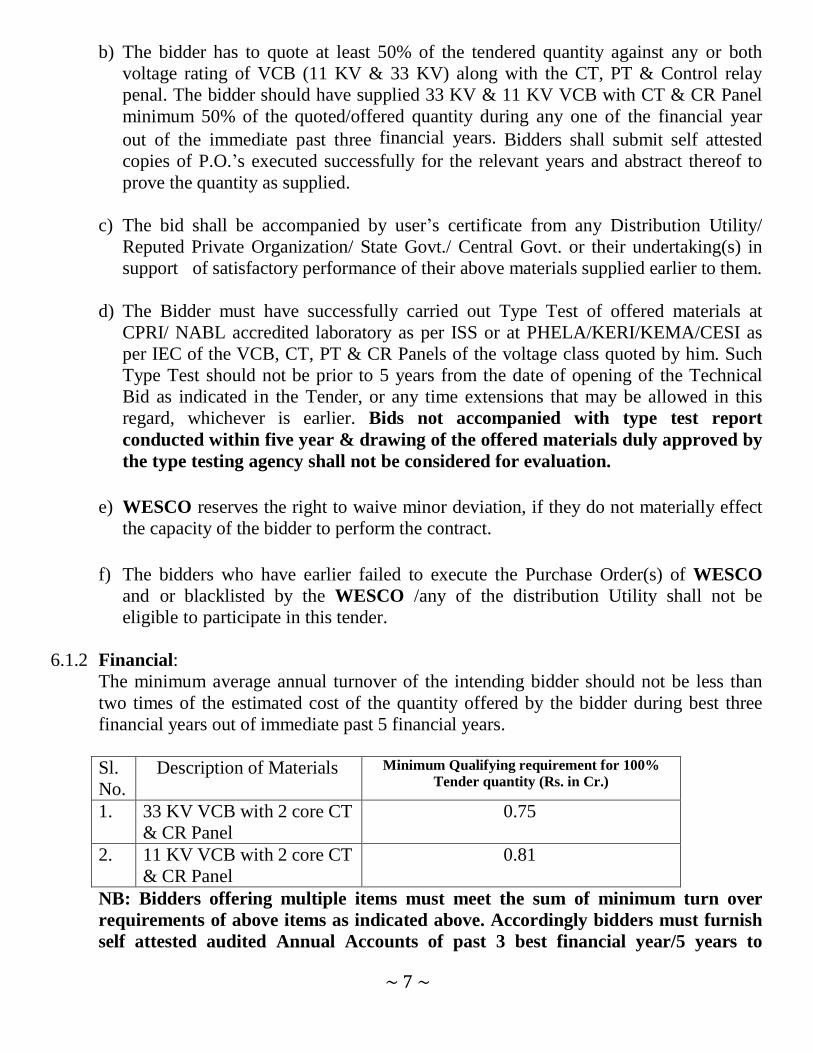
6.1.2 Financial:
The minimum average annual turnover of the intending bidder should not be less than
two times of the estimated cost of the quantity offered by the bidder during best three
financial years out of immediate past 5 financial years.
Sl.
No.
Description of Materials Minimum Qualifying requirement for 100%
Tender quantity (Rs. in Cr.)
1. 33 KV VCB with 2 core CT
& CR Panel
0.75
2. 11 KV VCB with 2 core CT
& CR Panel
0.81
NB: Bidders offering multiple items must meet the sum of minimum turn over
requirements of above items as indicated above. Accordingly bidders must furnish
self attested audited Annual Accounts of past 3 best financial year/5 years to

~ 8 ~
establish their Turnover requirement.
6.1.3 Participation of SSI Units by forming a CONSORTIUM: Two or more SSI Units having been manufacturer of tender items as per this tender
specification may form a Consortium among themselves and apply against
this specification, provided they fulfill the following eligible criteria.
a) They should have legally valid consortium agreement as per the prescribed format
for the purpose of participation in the bidding process. The total no of a consortium
shall be limited to four members.
b) All members of the Consortium should be the eligible manufacturer(s) of the
materials / equipments tendered.
c) Each member should have valid statutory license to use ISI Mark/BEE three star or
more level Certification/Type tested report from NABL accredited laboratory
conducted within last five years for the tendered materials/equipments as applicable
for the tender.
d) Consortium as a whole shall meet the qualifying norms specified in the tender, they
participate.
e) The lead member of the Consortium should meet at least 50% of the qualifying
norms in respect of the supply experience.
f) Besides the lead member, other member (s) of the Consortium should meet at least
15% of the qualifying norms in respect of the supply experience.
g) All the Consortium member(s) shall authorize the lead partner by submitting a
power of Attorney as per the prescribed format duly signed by the authorized
signatories. The lead partner shall be authorized to receive instructions for and on
behalf of all partners of the Consortium and entire execution of the contract.
h) The Consortium and its members shall be jointly and severally responsible and be
held liable for the purpose of guaranteed obligation and any other matter as required
under the contract.
i) Any member of the Consortium member(s) shall not be eligible either in an
individual capacity or part of any other consortium to participate in the tender, where
the said consortium participates.
j) Separate Purchase Orders will be placed to each members of the Consortium
considering their offer quantity and ability to supply.

~ 9 ~
k) The prescribed formats for Consortium Agreement (Annexure – VII) and Power of
Attorney (Annexure – VIII) are provided in the tender specification as enclosures.
6.1.4 Documentation:
6.1.4.1 Bidder shall furnish copies of original documents defining the constitution or legal
status, place of registration and principal place of business namely of Memorandum
and Article of Association.
6.1.4.2 Written power of attorney / Board Resolution of the authorized signatory of the bid.
6.1.4.3 Bidders shall submit their audited financial reports for best three financial years out
of last five years. In case the Bidder is in existence for less than 5 years the
audited financial report/s from the date of its incorporation should be furnished.
6.1.4.4 Copies of Purchase order successfully executed, Users Performance Certificate,
type Test Report if any.
7.0 All correspondence with regard to the above shall be made to the following address:
Western Electricity Supply Company of Odisha Ltd. (WESCO)
Corporate Office:
Burla – 768017
Ph. No. 0663-2432804, Fax: 0663-2432804

~ 10 ~
SECTION – II
INSTRUCTION TO BIDDERS (ITB)
SECTION – II

~ 11 ~
INSTRUCTION TO BIDDERS (ITB)
1.0 SOURCES OF FUNDS:
1.1 WESCO hereinafter referred to as the “Purchaser” is desirous of procurement of
materials for strengthening and improvement of distribution network under WESCO from
the funds available under CAPEX Programme of Govt. of Odisha.
2.0 SCOPE OF WORK:
2.1 The scope of work in brief shall include design, manufacture, type testing, inspection,
supply, loading at factory, transportation to site / stores, unloading at site/stores including
guaranteed obligation of complete supply of materials in conformity to the technical
specification enclosed herewith in Section – IV.
3.0 DISCLAIMER: 3.1 This Document includes statements, which reflect various assumptions, which may or
may not be correct. Each Bidder should conduct its own estimation and analysis and
should check the accuracy, reliability and completeness of the information in this
Document and obtain independent advice from appropriate sources in their own interest.
3.2 Neither Purchaser nor its employees will have any liability whatsoever to any Bidder or
any other person under the law or contract, the principles of restitution or unjust
enrichment or otherwise for any loss, expense or damage whatsoever which may arise
from or be incurred or suffered in connection with anything contained in this Document,
any matter deemed to form part of this Document, provision of Services and any other
information supplied by or on behalf of Purchaser or its employees, or otherwise arising
in any way from the selection process for the Supply / provision of Services for the
Project.
3.3 Though adequate care has been taken while issuing the Bid document, the Bidder
should satisfy himself that documents are complete in all respects. Intimation of any
discrepancy/ doubt shall be sent to the Purchaser address for speedy response.
3.4 This document and the information contained herein are Strictly Confidential and are for
use of only the person (s) to whom it is issued/ downloaded from the website. It may
not be copied or distributed by the recipient to third parties (other than in
confidence to the recipient‟s professional advisors).
4.0 COST OF BIDDING:
4.1 The Bidder shall bear all costs associated with the preparation and submission of its Bid
and Purchaser will in no case be responsible or liable for those costs.
5.0 BIDDING DOCUMENTS:
~ 12 ~
5.1 The Scope of Work, Bidding Procedures and Contract Terms are described in the
Bidding Documents. In addition to the covering Letter accompanying Bidding
Documents, the Bidding documents include:
a) Invitation of Bids (IFB) : Section - I
b) Instruction to Bidders (ITB) : Section - II
c) General Terms and Conditions of Contract (GTCC) : Section - III
d) Technical Specification : Section - IV
e) List of Annexure : Section – V
5.2 The Bidder is expected to examine the Bidding Documents, including all Instructions,
Forms, Terms and specifications. Failure to furnish all information required in the
Bidding documents or submission of a Bid not substantially responsive to the Bidding
Documents in every respect will / may result in the rejection of the Bid.
6.0 AMENDMENT OF BIDDING DOCUMENTS: 6.1 At any time prior to the deadline for submission of Bids, the Purchaser may, for any
reason, whether at its own initiative or in response to a clarification requested by a
prospective Bidder, modify the Bidding Documents by way of issuing an addendum.
6.2 The Amendment/ Addendum shall be part of the Bidding Documents, pursuant to Clause
6.1, and it will be binding on the bidders.
6.3 In order to afford prospective Bidders reasonable time in which to take the amendment
into account in preparing of their Bids, the Purchaser may, at its discretion, extend the
deadline for the submission of Bids.
7.0 LANGUAGE OF BID: The Bid, prepared by the Bidder, and all correspondence and documents relating to the Bid
exchanged by the Bidder and the Purchaser, shall be written in the English Language. Any
printed literature furnished by the Bidder may be written in another Language, provided
that the literature is accompanied by an English translation, in which case, for purposes of
interpretation of the Bid, the English translation shall govern.
8.0 DOCUMENTS COMPRISING THE BID:
8.1 The Bid prepared and submitted by the Bidder shall comprise of two parts i.e.
Part-I (Techno-Commercial Bid), & Part-II (Price Bid):
(A) The Part-I (Techno-Commercial Bid) must contain the following documents:
(a) Bid Document signed by the bidder in every page, all other Schedules / Formats
enclosed in the Bid-Document (i.e. Annexure-I, II, IV, V, VI (A), VI (B), VII, VIII, IX
& X) duly filled in & signed by the bidder with seal in a separate envelop superscribed
as Techno Commercial Bid. Bids containing information in formats other than our

~ 13 ~
prescribed formats shall not be acceptable and may make the bid non-responsive.
(b) Requisite Earnest Money Deposit (E.M.D) as per clause No. 4 of Section –I, IFB in a
separate envelop superscribed as “EMD” failing which the bid may be treated non-
responsive.
(c) Following Documentary evidence establishing in accordance with Clause-29, ITB,
that the Bidder is qualified to perform the Contract if the Bid is accepted:
i) Self attested copies of Purchase Orders executed in last 3 Years.
ii) Self attested copies of Performance Certificates / Successful contract
completion Certificates from the buyers preferably from Electricity Distribution
Utilities / Government Organizations.
iii) Self attested copies of Type Test Reports from CPRI / NABL Accredited
Testing Laboratory/PHELA/KERI/KEMA/CESI for the offered equipments along
with the copies of drawings duly approved by the Type Testing Agency for the tests
conducted not before 5 years from the date of opening of Bids.
iv) Copies of Profit & Loss Accounts & Audited Balance sheet indicating Turnover for
best 3 financial years out of last 5 financial years.
(d) Power of Attorney / Board resolution indicating that the person(s) signing the Bid
have the authority to sign the Bid and as such the Bid is binding upon the Bidder
during the full period of its validity, in accordance with clause 14.
(e) Requisite Cost of Tender Document as per clause 4 of Section –I, IFB in shape of
account payee Bank draft from a Public Sector Bank in favour of “The Western
Electricity Supply Company of Odisha Ltd.” Payable at Burla/Sambalpur is to be
enclosed along with the Bid, if the document is downloaded from our web-site. Or else,
the Original Copy of Money Receipt for the payment made towards the cost of Tender
Document is to be enclosed along with Bid, if the document is directly purchased
from our Cash Counter at our Regd. Office.
(B) Part – II (Price Bid):
The Price Bid shall contain the price schedules as per the prescribed format enclosed
as (Annexure-V) duly filled in & signed by the bidder with seal.
(This shall be submitted in a double sealed envelope separately duly superscribed
as “Price Bid”).
9.0 SUBMISSION OF BID:
9.1 The Bidder shall complete and submit the Bid Document in duplicate enclosing all
documents at clause “8” above in two sealed envelopes for Original & Duplicate
separately, superscribing the Tender Notice No.: WESCO / CAPEX/ 33 KV & 11 KV
VCB /55 Date: 03.11.2014, Date of Opening: 24.11.2014 & Description of Material.
9.2 E.M.D:

~ 14 ~
9.2.1 The bidder shall submit E.M.D as a part of the bid in the prescribed manner for the
amount mentioned in Clause No.4 of Section –I.
9.2.2 The E.M.D is required to protect the Purchaser against the risk of bidder‟s conduct,
which would warrant the security‟s forfeiture.
9.2.3 The E.M.D shall be in the following form:
A/C payee demand draft in favour of Western Electricity Supply Company of
Odisha Ltd. issued by a Public Sector Bank payable at Burla/Sambalpur.
OR
Bank Guarantee in favour of “Western Electricity Supply Company of Odisha
Ltd.” issued by a Public sector bank encashable at local branch at
Burla/Sambalpur only. The BG shall be strictly as per the format enclosed at
Section – V, Annexure – X.
NB: In case of any deficiency such as the ownership of the security bond (other
than the issuing bank), deviation from the approved format, absence of signature
of witness etc. found in the EMD Bank Guarantee, the same shall be liable for
rejection upfront. The bidder will not be given any chance to rectify the same.
9.2.4 Unsuccessful bidder‟s E.M.D shall be refunded back as promptly as possible, but
not later than thirty (30) days after the expiry of the period of bid validity. The
successful bidder‟s E.M.D shall be discharged upon furnishing of the performance
security.
9.2.5 The E.M.D may be forfeited due to following reasons:
1) If the bidder withdraws bid during the period of bid validity specified by the bidder
in the bid form.
2) In case the successful bidder fails to sign the contract in specified time and / or
fails to submit the requisite performance Bank guarantee.
3) In case of failure to supply the materials / equipment during the contractual
delivery Period.
10.0 BID PRICE:
10.1 Bidders have to quote for the entire quantity of materials/equipment covered under
this specification strictly as per the enclosed format in Section –V. The total Bid Price
shall also cover all the Supplier‟s obligations mentioned in or reasonably to be
inferred from the Bidding Documents in respect of Design, Supply, testing,
inspection, Transportation to site/stores, all in accordance with the requirement of
Tender Documents.
The Bidder shall complete the appropriate Price Schedules enclosed herein at

~ 15 ~
Annexure – V, stating the Unit Price for each item, all other livable taxes & duties,
freight & insurance separately and thereby arriving at the total amount.
10.2 In case there is any increase in the number of units as compared to those mentioned
in the IFB, the Contract Price shall be subject to increase proportionately on pro-rata
basis.
10.3 The Price offered shall be inclusive of all costs as well as Duties, Taxes and Levies
paid or payable during implementation of the contract. If the Bidder is exempted from
Excise duties, Concession in the Sales tax, levy of entry tax, same should be clearly
mentioned supported with documentary evidence.
10.4 Prices quoted by the Bidder shall be “Firm” and not subject to any price adjustment
during the performance of the Contract. A Bid submitted with variable Price or an
adjustable price clause shall be treated as non-responsive and rejected out rightly.
11.0 CONTRACT PRICE:
11.1 The Ex-Works Prices quoted for the Contract shall remain FIRM as per the above
Parameters and Purchaser shall not compensate Bidder for any variations. However any
variation in the taxes & duties within the schedule date of delivery shall be borne by the
Purchaser, else the same shall be borne by the bidder.
11.2 In case the Purchaser, revise the scope of woks, bidders shall be compensated based
on the Unit Rate (Ex-Works) agreed upon before Order placement or as per mutually
acceptable rates.
12.0 BID CURRENCIES: 12.1 Prices shall be quoted in Indian Rupees Only.
13.0 DOCUMENTS ESTABLISHING CONFORMITY TO THE BIDDING
DOCUMENTS: 13.1 The bidder shall confirm by documentary evidence of the Good‟s conformity to the
Bidding Documents by submitting materials/equipment data sheets.
14.0 PERIOD OF VALIDITY OF BIDS: 14.1 Bids shall remain valid for 180 days from the date of opening of commercial Bids.
14.2 Notwithstanding Clause 14.1 above, the Purchaser may solicit the Bidder‟s consent to
an extension of the Period of Bid Validity. The request and the responses thereto shall be
made in writing or by Fax.
15.0 ALTERNATIVE BIDS: 15.1 Bidders shall submit Bids, which comply with the Tender Documents. Alternative bids
shall not be considered for evaluation. However, if the bidder(s) prefer to submit the
revised price bid before the due date of opening of the price bid, the revised price bid
shall be considered for evaluation.

~ 16 ~
16.0 FORMAT AND SIGNING OF BID: 16.1 The original Bid Form and accompanying documents (as specified in Clause 9 ),
clearly marked “Original Bid”, plus one copy of the Techno-Commercial Proposal must
be received by the Purchaser at the date, time and place specified pursuant to Clauses 17
and 18.
The Price Bid in Original should be submitted in a separate sealed envelope marked as
“Price Bid”. In the event of any discrepancy between the original and the copies, the
original shall govern.
16.2 The original and the duplicate copy of the Bid shall be typed or written legibly and shall
be signed by the Bidder or a person or persons duly authorized to sign on behalf of the
Bidder. Such authorization shall be indicated by written Power-of-Attorney/
Board Resolution accompanying the Bid.
16.3 The Bid shall contain no interlineations, erasures, overwriting except as necessary to
correct errors, made by the Bidder, in which case such corrections shall be initialed by the
person or persons signing the Bid.
17.0 SEALING AND MARKING OF BIDS: 17.1 Bid submission: One Original, One Copy of all the Bid Documents shall be sealed
and submitted to the Purchaser before the last date & time for submission of the bid.
17.2 The Bid proposal should be divided into two parts and should be submitted in two
separate sealed envelopes, addressed to Purchaser. All the envelopes should bear the
Name and Address of the Bidder and marking is made for the Original and the duplicate
copy. The envelopes should be superscribed with the title of its contents, as follows:
i) TECHNO-COMMERCIAL BID ENVELOPE: Shall contain the Bid Security
(EMD), Cost of Tender Document, all supporting documents for qualifying
requirement of this tender, duly filled in formats Abstract of General Terms &
Conditions, Declaration Form, Technical Data Schedule, Technical & Commercial
Deviations formats, Un-quoted blank Price Schedule etc. enclosed at Annexure I, II,
IV, V, VI (A), VI (B), VII, VIII, IX & X at Section-V of this document.
ii) PRICE BID ENVELOPE: Shall contain the Price schedule duly filled in & signed
as per Annexure –V at Section-V of this document. (This shall be submitted in a
double sealed envelope separately.)
17.3 The inner and outer envelopes shall:

~ 17 ~
a) Be addressed to the Purchaser at the following address:
General Manager (O&M) & Purchase
Western Electricity Supply Company of Odisha Ltd. (WESCO)
Corporate Office, Burla – 768017
Ph. No. 0663-2432804, Fax: 0663-2432804
Bear the Project name as: “Design, Manufacture, Testing, Inspection and Supply of
33 kV & 11 kV VCBs with CT & CR Panels as per Schedule of Requirement in
Section-I) – Tender Notice No.: WESCO / CAPEX/ 33 KV & 11 KV VCB /55 Date:
03.11.2014.
In addition to the information required in sub clause (a) and (b) above, the outer
envelope shall indicate the name and address of the Bidder to enable the Bid to be
returned unopened in case it is declared “Late” pursuant to Clause 20.
17.4 The Bidders have the option of sending the Bids by Post/ Courier services or in person.
Bids submitted by Telex/Telegram/Fax will not be accepted. No request from any Bidder
to the Purchaser to collect the proposals from Airlines/ Cargo/Courier Agents etc. shall
be entertained by the Purchaser.
18.0 DEADLINE FOR SUBMISSION OF BIDS:
18.1 The original Bid together with required copies, must be received by the Purchaser at
the address specified in Clause 17.3 not later than 13.00 Hrs. (IST) on/before the due date
as indicated in the invitation for bids.
18.2 The Purchaser may, at its discretion, extend the deadline for the submission of Bids
by amending the Bidding Documents, in which case all rights and obligations of the
Purchaser and Bidders previously subject to the deadline will thereafter be subject to the
deadline as extended.
19.0 ONE BID PER BIDDER: 19.1 Each Bidder shall submit only one Bid either by himself, or as a partner in a
Joint Venture/Consortium. A Bidder who submits or participates in more than one Bid for
the same item, either individually or jointly, will cause all those Bids to be rejected out
rightly.
20.0 LATE BIDS: 20.1 Any Bid received by the Purchaser after the deadline for submission of Bids prescribed by
the Purchaser, pursuant to Clause 18, will be declared “Late” and will be rejected out
rightly and will be returned unopened to the Bidder.
21.0 MODIFICATION AND WITHDRAWAL OF BIDS:

~ 18 ~
21.1 The Bidder may modify or withdraw his Bid after the Bid‟s submission, provided that
written notice of the modification or withdrawal is received by the Purchaser prior to the
deadline prescribed for submission of Bids.
21.2 The Bidder‟s modification or withdrawal notice shall be prepared, sealed, marked
and dispatched in accordance with the provisions of Clause 17 & 18. A withdrawal notice
may be sent by fax but must be followed by an original signed confirmation copy.
21.3 No Bid can be modified subsequent to the deadline for submission of Bids.
21.4 No Bid can be withdrawn in the interval between the deadline for submission of Bids and
the expiry of the period of Bid validity specified by the Bidder on the Bid form as per
clause 14.
22.0 EVALUATION OF BID:
22.1 PROCESS TO BE CONFIDENTIAL:
Information relating to the examination, clarification, evaluation and comparison of Bids
and recommendations for the award of a contract shall not be disclosed to Bidders or any
other persons not officially concerned with such process. Any effort by a Bidder to
influence the Purchaser‟s processing of Bids or award decisions may result in the rejection
of the Bidder‟s Bid.
23.0 CLARIFICATION OF BIDS: To assist in the examination, evaluation and comparison of Bids, the Purchaser may, at its
discretion, ask the Bidder for a clarification of its Bid. All responses to requests for
clarification shall be in writing and no change in the price or substance of the Bid shall be
sought, offered or permitted.
24.0 PRELIMINARY EXAMINATION OF BIDS / RESPONSIVENESS: 24.1 Purchaser will examine the Bids to determine whether they are complete, whether
any computational error have been made , whether required sureties have been furnished,
whether the documents have been properly signed, and whether the Bids are generally in
order.
24.2 Arithmetical errors will be rectified on the following basis. If there is a discrepancy
between the unit price and the total price per item that is obtained by multiplying the unit
price and quantity, the unit price shall prevail and the total price per item will be
corrected. If there is a discrepancy between the total amount and the sum of the total price
per item, the sum of the total price per item shall prevail and the Total Amount will be
corrected.
24.3 Prior to the detailed evaluation, pursuant to Clause 25, the Purchaser will determine
the substantial responsiveness of each Bid to the Bidding Documents including production

~ 19 ~
capability and acceptable quality of the materials offered, pursuant to Clause 13.
Substantially responsive Bid is one, which conforms to all the terms and conditions of the
Bidding Documents without material deviation.
24.4 A Bid determined as not substantially responsive will be rejected by the Purchaser and
will not subsequently allowed to be made responsive by the Bidder by correction of the
non – conformity.
25.0 EVALUATION AND COMPARISON OF BIDS: 25.1 The evaluation of Bids shall be done basing on the delivered cost competitiveness
basis for each item separately.
25.2 The evaluation of the Bids shall be a stage-wise procedure. The following stages are
identified for evaluation purposes:
In the first stage, the Bids would be subjected to a responsiveness check as detailed in
the clause 24. The Technical Proposals and the Commercial terms & conditions of the
Bidders would be evaluated and discussed as per clause 26 of this document.
Subsequently, the Financial Proposals along with Supplementary Financial Proposals, if
any, of Bidders with Techno-commercially Acceptable Bids submitted prior to final
evaluation shall be considered.
25.3 The Purchaser’s evaluation of a Bid will take into account, in addition to the Bid
price, the following factors, in the manner and to the extent indicated in this Clause:
a) Delivery Schedule.
b) Deviations from Bidding Documents as mentioned in Non-Compliance Schedule.
c) Past performance and capability to execute the contract.
d) Type test reports from CPRI/ NABL Accredited Laboratories/
PHELA/KERI/KEMA/CESI.
Bidders shall base their Bid price on the terms and conditions specified in the Bidding
Documents. The Cost of all quantifiable deviations and omissions from the
specification, terms and conditions, specified in Bidding Documents shall be evaluated.
The Purchaser will make his own assessment of the cost of any deviation for the purpose
of ensuring fair comparison of Bids.
26.0 AWARD OF CONTRACT: In normal circumstances the Purchaser will generally award the Contract to the
successful Bidder whose Bid has been determined to be the lowest evaluated responsive
Bid, provided further that the Bidder has been determined to be qualified to perform the
Contract satisfactorily. If the lowest evaluated prices (L1) of more than one responsive
bidder(s) are same, then in such event the tender quantity shall be awarded in equal

~ 20 ~
proportion.
However, for timely completion of the project, the purchaser may distribute the order
among the bidders (maximum three) at L1 rate. In case of distributing between two
bidders, the ratio shall be 70% (L1): 30% (L2) or the quantity offered/quoted by the
bidders whichever is less. Similarly in case of distributing among 3 bidders, the ratio
shall be 50% (l1):30% (L2):20 (L3).
In case L2 & L3 bidders does not agree to match the L1 prices, negotiation can be held
with other techno-commercially responsive L4, L5 …….bidders in sequence to match L1
price (Landed cost).
26.1 CONTACTING THE PURCHASER: 26.1.1 From the time between Bid opening to award of contract, if any Bidder wishes to
contact the Purchaser on any matter related to the Bid, he should do so in writing.
26.1.2 Any effort by a Bidder to influence the Purchaser and / or in the Purchaser‟s
decisions in respect of Bid evaluation, Bid comparison or Contract of Award, will
result in the rejection of the Bidder‟s Bid.
26.2 THE PURCHASER’S RIGHT TO ACCEPT ANY BID AND TO REJECT ANY
OR ALL BIDS OR TO RELAX ANY TERMS AND CONDITIONS: 26.2.1 The Purchaser reserves the right to accept or reject any Bid and to annul the Bidding
process and reject all Bids at any time prior to award of Contract, without thereby
incurring any liability to the affected Bidder or Bidders or any obligation to inform
the affected Bidder or Bidders regarding the grounds for the Purchaser‟s action.
26.2.2 In the interest of work, the Purchaser reserves the right to relax any terms and
conditions without affecting the quality & price of the equipments.
26.3 The Purchaser will award the Contract to the successful Bidder whose Bid has
been determined to be the lowest- evaluated responsive Bid, provided further that the
Bidder has been determined to be qualified to perform the Contract satisfactorily. The
Purchaser at its option/ discretion may split the total quantity to be supplied between two
or more Techno- Commercially responsive Bidders in case of the bid prices are same
and early delivery is required by the purchaser.
26.4 THE PURCHASER’S RIGHT TO VARY QUANTITIES: The Purchaser reserves the right to vary the quantity i.e. increase or decrease the number
of materials without any change in terms and conditions at the time of placing the
orders or during the execution of the Contract.
26.5 LETTER OF INTENT / NOTIFICATION OF AWARD: 26.5.1 The letter of intent / Notification of Award shall be issued to the successful

~ 21 ~
Bidder(s) whose bid(s) have been considered responsive, techno-commercially
acceptable and evaluated to be the Lowest (L1). The successful Bidder shall be
required to furnish a letter of acceptance to it within 7 days of issue of the letter of
intent / Notification of Award by Purchaser.
27.0 PERFORMANCE SECURITY: 27.1 Within 10 days of the receipt of Notification of Award / Letter of Intent from the
Purchaser, the successful Bidder shall furnish the Performance Security in the form of
Bank Guarantee executed on non-judicial stamp paper worth Rs.100/- (Rupees One
hundred only) issued by a Public Sector Bank in favour of the Purchaser encashable at
Burla/Sambalpur only for an amount of 10% (ten percent) of the Contract Price in
accordance with the General Conditions of Contract in the Performance Security Form
provided in Section –V of Bidding Documents.
The Bank Guarantee shall be valid for a period not less than 90 days over and above the
guarantee period.
28.0 CORRUPT OR FRAUDULENT PRACTICE: 28.1 The Purchaser requires that the Bidders observe the highest standard of ethics during
the procurement and execution of the Project. In pursuance of this policy, the Purchaser:
a) Defines, for the purposes of this provision, the terms set forth below as follows:
i) “Corrupt practice” means behavior on the part of officials in the public or
private sectors by which they improperly and unlawfully enrich themselves
and/ or those close to them, or induce others to do so, by misusing the position in
which they are placed, and it includes the offering, giving, receiving, or
soliciting of anything of value to influence the action of any such official in the
procurement process or in contract execution; and
ii) “Fraudulent practice” means a misre1presentation of facts in order to influence
a procurement process or the execution of a contract to the detriment of the
Purchaser, and includes collusive practice amount Bidders (prior to or after Bid
submission ) designed to establish Bid prices at artificial non-competitive levels
and to deprive the Purchaser of the benefits of free and open competition.
b) Purchaser will reject a proposal for award if it determines that the Bidder
recommended for award has engaged in corrupt or fraudulent practice in
competing for the contract in question.
c) Purchaser will declare a firm ineligible, either indefinitely or for a stated period of
time, to be awarded an contract if he at any time determines that the firm is
engaged in corrupt or fraudulent practice in competing for, or in executing, the
Contract.

~ 22 ~
28.2 Further more, Bidders shall be aware of the provision stated in the General
Terms and Conditions of Contract.
29.0 LITIGATION HISTORY:
The Bidder should provide accurate information on any litigation or arbitration resulting
on contracts completed or under execution by him over the last three (3) years. A
consistent history of awards involving litigation against the Bidder or any Partner of the
joint venture/Consortium may result in disqualification of Bid.

~ 23 ~
SECTION – III
GENERAL TERMS AND CONDITIONS OF
CONTRACT (GTCC)
SECTION – III
GENERAL TERMS AND CONDITIONS OF CONTRACT (GTCC)
1.0 GENERAL INSTRUCTIONS:

~ 24 ~
1.01 All the Bids shall be prepared and submitted in accordance with these instructions.
1.02 Bidder shall bear all costs associated with the preparation and delivery of its Bid, and
the Purchaser will in no case shall be responsible or liable for these costs.
1.03 The Bid should be submitted by the Bidder in whose name the bid document has
been issued and under no circumstances it shall be transferred / sold to the other party.
1.04 The Purchaser reserves the right to request for any additional information and also
reserves the right to reject the proposal of any Bidder, if in the opinion of the
Purchaser, the data in support of Tender requirement is incomplete.
1.05 The Bidder is expected to examine all instructions, forms, terms & conditions and
specifications in the Bid Documents. Failure to furnish all information required in the
Bid Documents or Submission of a Bid not substantially responsive to the Bid
Documents in every respect may result in rejection of the Bid. However, the
Purchaser‟s decision in regard to the responsiveness and rejection of bids shall be final
and binding without any obligation, financial or otherwise, on the Purchaser.
2.0 DEFINITION OF TERMS:
2.1 WESCO shall mean the “Purchaser” on whose behalf this bid enquiry is issued by
its authorized representative / officers.
2.2 “Bidder” shall mean the firm who quotes against this bid document issued by the
Purchaser. “Contractor / Seller” shall mean the successful Bidder(s) whose bid has
been accepted by the Purchaser and shall include his heirs, legal representatives,
successors and permitted assigns.
2.3 “Site” shall mean the Electricity Distribution Area of the Purchaser.
2.4 “Specification” shall mean collectively all the terms and stipulations contained in those
portions of this bid document known as Instruction to Bidder, Bid form and other
forms as per Section –V, General Conditions of Contract, Specifications and the
Amendments, Revisions, Deletions or Additions, as may be made by the Purchaser
from time to time.
2.5 “Letter of Intent” shall mean the official notice issued by the Purchaser notifying the
Contractor that his proposal has been accepted and it shall include amendments thereto,
if any, issued by the Purchaser. The “Letter of Intent” issued by the Purchaser shall be
binding on the “Contractor”. The date of detailed Purchase Order shall be taken as the
effective date of the commencement of contract.
2.6 “Month” shall mean the calendar month and “Day” shall mean the calendar day.
2.7 “Codes and Standards” shall mean all the applicable codes and standards as indicated
in the Technical Specification.
2.8 “Offer Sheet” shall mean Bidder‟s firm offer submitted to Purchaser in accordance
with the specification.
2.9 “Contract” shall mean the “Detailed Purchase Order” issued by the Purchaser.
2.10 “Contract Price” shall mean the Price referred to in the “Detailed Purchase Order.
2.11 “Contract Period” shall mean the period during which the “Contract” shall be
executed as agreed between the Contractor and the Purchaser in the Contract
inclusive of extended contract period for reasons beyond the control of the Contractor

~ 25 ~
and / or Purchaser due to force majeure.
2.12 “Goods/Materials” shall mean all items to be supplied under Purchase Order whether
raw materials, processes materials, equipment, fabricated Materials, drawings
or other documents etc. as applicable.
2.13 “Store” shall mean the Purchaser‟s Store as given in the tender document.
2.14 “Project / Unit” shall mean supply of Materials as per enclosed technical specification.
3.0 CONTRACT DOCUMENTS & PRIORITY: 3.1 Contract Documents: The Specification, terms and conditions of the contract shall
consist solely of these Tender conditions and offer sheet.
3.2 Priority: Should there be any discrepancy between any terms hereto and any term of
the offer sheet, the terms of this tender document shall prevail.
4.0 SCOPE OF WORK: 4.1 The “Scope of Work” shall be on the basis of Bidder‟s responsibility, completely
covering the obligations, responsibility and workmanship, provided in this Bid Enquiry
whether implicit or explicit.
4.2 The Purchaser reserves the right to vary the quantity, i.e., increase or decrease, at the
time of placing order or during project execution.
4.3 All relevant drawings, data and instruction manuals and other necessary inputs shall
be under the scope of contract.
5.0 GENERAL REQUIREMENTS:
5.1 The seller shall supply, deliver best quality Goods/Materials/Equipments & conduct
the testing at their works of highest standards.
6.0 The seller shall be responsible & shall comply with the provisions of all statutory acts,
i.e., Electricity Act 2003, Indian Electricity Rules 1956, Income Tax Act-1961 etc.
7.0 INSPECTION & TESTING: (i) The Purchaser‟s representative shall be entitled at all reasonable times during
manufacture to inspect examine and test on the Contractor‟s premises the materials and
workman-ship of all equipment to be supplied under this contract and if part of the said
equipment is being manufactured elsewhere in any Sub-Contractor‟s premises, the
Contractor shall obtain for the Purchaser‟s representative, permission to inspect,
examine and test as if the equipment were being manufactured on the Contractor‟s
premises. Such inspection, examination and testing shall not release the Contractor
from his obligations under the contract.
(ii) The Contractor shall give to the Purchaser adequate time/ notice (minimum of two weeks
time) in writing for inspection of materials indicating the place at which the equipment
is ready for testing and inspection and shall also furnish the Routine Test Certificates
and Packing List along with offer for inspection to the Purchaser indicating the
quantity which can be delivered in full truck load / Mini truck load to facilitate issue of

~ 26 ~
dispatch instruction.
(iii) Where the contract provides for test on the Premises of the Contractor or of any of his
Sub-Contractors, the Contractor shall provide such assistance, labour, materials,
electricity, fuel and instruments as may be required or as may be reasonably demanded
by the Purchaser‟s representative to carry out such tests efficiently. The Contractor is
required to produce Shop Routine Test Certificates before offering their materials for
inspection.
(iv) After completion of the tests as indicated above, the Purchaser‟s representative shall
forward the test results to the Purchaser. If the test results confirm to the specific
standard, the Purchaser shall approve the test results and communicate the same to the
Contractor in writing. The Contractor shall provide atleast three copies of the test
certificates to the Purchaser.
(v) The Purchaser has the right to have the test carried out at his own cost by an
independent agency whenever there is a dispute regarding the quality of supply.
(vi) The Purchaser at its discretion may re-test the Materials/Equipment at its own
laboratory or laboratory of his choice for reconfirmation of the test results, particularly
no load losses, load losses and percentage impedance, etc.
(vii) Besides the above, the Third Party Independent Evaluation Agency (TPIEA)
engaged by GRIDCO shall have right to conduct the pre & post dispatch inspection
(as explained above) of the equipment/material procured by the Purchaser jointly
along with the representative of purchaser/independently by the TPIEA as the case
may be.
8.0 TRAINING FACILITIES: The Contractor shall provide all possible facilities for training of Purchaser‟s Technical
personnel, when deputed by the Purchaser for acquiring firsthand knowledge in
assembly of the equipment and for its proper operation and maintenance in service.
9.0 REJECTION OF MATERIALS:
In the event, any of the materials / equipment supplied by the Contractor is found
defective due to faulty design, bad workmanship, bad materials used or otherwise not in
conformity with the requirements of the Specification, the Purchaser shall either reject the
materials / equipment or ask the Contractor in writing to rectify the same.
The Contractor on receipt of such notification shall either rectify or replace the
defective materials/equipment free of cost to the Purchaser. If the Contractor fails to do
so, the Purchaser may:
a) At its option replace or rectify such defective materials/equipment and recover the
extra costs so involved from the Contractor plus (15%) fifteen percent and / or.

~ 27 ~
b) Terminate the contract for balance work / supplies with enforcement of penalty
Clause as per contract for the un-delivered materials and with forfeiture of Performance
Guarantee/ Composite Bank Guarantee.
c) Acquire the defective equipment / materials at reduced price considered equitable
under the circumstances.
10.0 EXPERIENCE OF BIDDERS : 10.1 The bidder(s) should furnish information regarding experience particularly on the
following points :
a) Name of the manufacturer:
b) Standing of the firm for manufacture of equipment/material quoted:
c) Description of materials/equipment supplied during the last 3 (three) years with the
name (s) of the party (s) to whom supplies were made.
d) Testing facilities at manufacturer‟s work with copies of calibrated certificates of the
major testing equipment.
e) If the manufacturer is having collaboration with other firm(s), details regarding the
same:
f) A list of Purchase orders, executed during the last three years along with user‟s
certificate and copies of Purchase orders. Excise invoices & Store Receiving Voucher
to be submitted for the supplied materials is a must for the bidder.
10.2 Bids may not be considered if the past manufacturing experience is found to be
un- satisfactory as mentioned under clause -6 of the IFB.
11.0 LANGUAGE AND MEASURES: All documents pertaining to the contract including Specifications, Schedule, Notice,
Correspondence, Operating & Maintenance instructions, Drawings or any other
writing shall be written in English language. The metric system of measurement shall be
used exclusively in this contract.
12.0 DEVIATION FROM SPECIFICATION : It is in the interest of the Bidders to study the Specification, drawing etc. specified in the
tender document thoroughly before tendering so that, if any deviations are made by the
Bidders, the same are prominently brought out on a separate sheet in the Technical &
Commercial Deviation Formats enclosed at Annexure VI (A) & VI (B) in this document.
Deviation mentioned in any other format or any other part of the offer document shall
not be considered as a deviation & in such case it will be presumed that the bidder has
accepted all the conditions, stipulated in the tender Specification, notwithstanding any
exemptions mentioned therein.
13.0 PRICE BASIS:

~ 28 ~
13.01 (a) Bidder shall quote “FIRM” price.
The breakup of prices shall indicate all types of Taxes, Duties and other
Levies of whatsoever nature indicated separately and clearly, Packing & forwarding,
transportation to site/store including transit insurances and entry tax etc. Exemption
from any duties/taxes, if any, shall be supported with relevant documentary evidence.
(b) The above Prices shall also include loading at factory site & unloading at Purchaser‟s
site/stores. Price evaluation will be based on total landing cost, taking into account all
taxes and duties.
(c) CST / VAT clearance certificate, Copy of PAN card.
14.0 TERMS OF PAYMENT: 100 % value of each consignment will be paid within 30 days of receipt of materials in
good conditions at stores/ desired destination and verification there of subject to approval
of the Guarantee certificates & Test Certificates and submission & acceptance of
Performance Bank Guarantee equivalent to 10 % of Total Contract Price on non-
judicial stamp paper worth Rs.100 in the prescribed format from a Public Sector
Bank encashable at Burla/Sambalpur only.
Or
Else an equivalent amount of 10 % of the Total Contract Price shall be deducted from
the invoice of the first consignment & the same shall be refunded after submission and
approval of the required Performance Bank Guarantee or expiry of Guarantee Period
whichever is earlier.
15.0 PRICE VALIDITY: 15.1 All bids submitted shall remain valid, firm and subject to unconditional acceptance
by Purchaser for 180 days post bid date. For award of Contract, the prices shall remain
valid and firm till contract completion.
16.0 GUARANTEE:
16.1 The bidder shall guarantee for satisfactory performance of the
equipments/materials for a minimum period of 60 months from the date of
Commissioning or 66 months from the date of receipt of last consignment
whichever is earlier. In the event of any defect in the equipment/ materials arising
out of faulty design, inferior quality of raw material used or bad workmanship within
the guarantee period, the Seller shall guarantee to replace/ repair to the satisfaction of the
Purchaser the defective equipments free of cost. Should however, the manufacturer fails
to do so within a reasonable time, the Purchaser reserves the right to recover the amount
from the seller either from the bills pending or may recover from the Performance
Guarantee submitted by the firm. Seller shall give a Performance Bank Guarantee in
favour of the Purchaser for 10% of the order value valid for 90 days over and
above the guarantee obligation.
16.2 If during the defect liability period any services performed found to be defective, these

~ 29 ~
shall be promptly rectified by seller at its own cost (including the cost of dismantling and
reinstallation) on the instruction of Purchaser.
17.0 RELEASE:
The seller‟s Performance Bank Guarantees / Assignable Bank Guarantee will be released
without interest within thirty (30) days from the last date up to which the Performance
Bank Guarantee has to be kept valid (as defined in Clause 16.01).
18.0 TECHNICAL INFORMATION / DATA: The Purchaser and the Contractor, to the extent of their respective rights permitting to do
so, shall exchange such technical information and data as is reasonably required by each
party to perform its obligations and responsibilities. The Purchaser and the Contractor
agree to keep each other in confidence and to use the same degree of care as he uses with
respect to his own proprietary data to prevent its disclosure to third parties of all
technical and confidential information. The technical information, drawings, records and
other document shall not be copied, transferred, traced or divulged and / or disclosed to
third party in full / part nor misused in any other form. This technical information,
drawing etc. shall be returned to the Purchaser with all approved copies and
duplicates. In the event of any breach of this Contract, the Contractor shall indemnify
the Purchaser against any loss, cost of damages of claim by any party in respect of such
breach.
19.0 EFFECTIVE DATE OF COMMENCEMENT OF CONTRACT:
19.1 The date of the issue of the detailed Purchase Order shall be treated as the effective date
of the commencement of Contract.
20.0 The bidder shall quote the basic price as well as all taxes & duties as per the enclosed
format for bid prices.
21.0 PENALTY:
21.1 If supply of materials / equipments is delayed beyond the supply schedule as stipulated
in Purchase order, then the seller shall be liable to pay to the Purchaser as penalty for
delay, a sum of 0.5% (half percent) of the contract price for every week delay or part
thereof.
21.2 The total amount of penalty for delay under the contract will be subject to a maximum
of five percent (5%) of the contract price.
21.3 The Purchaser may, without prejudice to any method of recovery, deduct the amount
for such damages from any amount due or which may become due to the seller or from
the Performance Bank Guarantee or file a claim against the seller.
22.0 VALIDITY OF THE ORDER: The Order is valid for 10 weeks beyond the schedule date of delivery, unless otherwise
extended by the Competent Authority. The Order shall stand cancelled automatically
beyond the validity period without any correspondences and liabilities to the purchaser.

~ 30 ~
23.0 PACKING: The materials / equipments shall be packed by the seller suitably as per the standard
procedure for safe transport to the site / store. The cases shall be clearly marked showing
distinctly the name and address of the consignee. In case of special instructions, such
as “this end up”, “fragile”, “handles with care” etc., the same shall be clearly displayed on
the cases.
24.0 COMMISSIONING SPARES: The seller shall replace, free of cost, any spares which may be found defective by the
buyer during commissioning.
25.0 DISPUTE RESOLUTION & JURISDICTION OF CONTRACT:
25.1 Any dispute arising out of this contract shall be referred to the MD/CMD, OPTCL
who shall decide the case as sole arbitrator.
25.2 For the purpose of dispute resolution, this agreement shall be governed by the provision
of Arbitration & Conciliation Act, 1996.
25.3 All disputes shall be subject to exclusive jurisdiction of the Court at Burla/Sambalpur
and Writ jurisdiction of Hon‟ble High Court of Odisha at Cuttack.
26.0 EVENTS OF DEFAULT: 26.1 Events of Default. Each of the following events or occurrences shall constitute an event
of default (“Event of Default”) under the Contract :
26.1.1 Seller fails or refuses to pay any amount due under the Contracts.
26.1.2 Seller fails or refuses to deliver Commodities conforming to his Bid document/
specifications, or fails to deliver Commodities and, or execute the works assigned to
them within the period specified in P.O or any extension thereof.
26.1.3 Seller becomes insolvent or unable to pay its debts when due, or commits any act of
bankruptcy, such as filing any petition in any bankruptcy, winding-up or
reorganization proceeding, or acknowledges in writing its insolvency or inability to
pay its debts; or the Seller‟s creditors file any petition relating to bankruptcy of Seller;
26.1.4 Seller otherwise fails or refuses to perform or observe any term or condition of the
Contract and such failure is not remediable or, if remediable, continues for a period of
30 days after receipt by the Seller of notice of such failure from Purchaser.
27.0 CONSEQUENCES OF DEFAULT:
a) If an Event of Default occurs and would be continuing, Purchaser may forthwith
terminate the Contract by written notice.
In the Event of Default, Purchaser may, without prejudice to any other right granted to it
by law, or the Contract, take any or all of the following actions;
(i) present for payment, to the relevant bank the Contract Performance Bank
Guarantee;
(ii) Recover any losses and / or additional expenses, Purchaser may incur as a result of
Seller‟s default.

~ 31 ~
28.0 FORCE MAJEURE: 28.01 The term “Force Majeure” as employed herein include, acts of God or force of
nature, landslide, earthquake, flood, fire, lightning, explosion, major storm (hurricane,
typhoon, cyclone etc. ) or major storm warning, tidal wave, shipwreck and perils of
navigation, act of war (declared or undeclared ) or public enemy, strike (excluding
employee strikes, lockouts or other industrial disputes or action solely among employee
of Contractor or its subcontractors ) act or omission of Sovereign States or those
purporting to represent Sovereign States, blockade, embargo, quarantine, public
disorder, sabotage, accident or similar events beyond the control of the parties or either
of them.
Force Majeure shall not include occurrences as follows:
1. Late delivery of materials caused by congestion of Seller‟s facilities or elsewhere, and
oversold condition of the market, inefficiencies, or similar occurrences.
2. Late performance by Seller and / or Sub-Seller caused by unavailability of raw
materials, supervisors or labour, inefficiencies of similar occurrences.
3. Mechanical breakdown of any item of Seller‟s or its Sub-Seller‟s equipment, plant or
machinery.
4. Delays due to ordinary storm or inclement weather or
5. Non-conformance by Sub-Seller.
Unless the delay arises out of a Force Majeure occurrence and is beyond both Seller‟s
and Sub-Seller‟s or Seller‟s control and an alternate acceptable source of services,
equipment or material is unavailable. Additionally, Force Majeure shall not include
financial distress of Seller or any Sub-Seller.
28.02 In the event of either party being rendered unable by Force Majeure to perform
any obligation required to be performed by them under the Contract, the relative
obligation of the party affected by such Force Majeure shall be suspended for the
period during which such cause lasts. Time for performance of the relative obligation
suspended by Force Majeure shall then stand extended by the period for which the
cause lasts.
28.03 Upon the occurrence of any Force Majeure event, the party so affected in the
discharge of its obligation shall promptly, but no later than seven (7) days give
written notice of such even to the other party. The affected party shall make every
reasonable effort to remove or remedy the cause of such Force majeure or mitigate its
effect as quickly as possible. If such occurrence results in the suspension of all or part
of the work for a continuous period of more than 10(ten) days, the parties shall meet
and determine the measures to be taken.
28.04 Any delay or failure in performance by either party hereto shall not give rise to any
claims for damages or loss of anticipated profits if and to the extent, such delay or

~ 32 ~
failure is caused by Force Majeure.
29.0 EMBOSSING / PUNCHING / CASTING: 29.1 The all equipments and materials supplied under the CAPEX Programme shall bear
distinct mark of “Name of the Purchaser, GoO, CAPEX Programme, Purchase Order No.
& Date” by a way of embossing / punching / casting etc. This should be clearly visible to
naked eye.
30.0 INDEMNIFY 30.1 The Vendor, its successor and assignee shall indemnify the Purchaser, its successor and
assignee from all current & future liabilities that may arise out of purchase contract(s)
entered into between the vendor & the Purchaser under this CAPEX Programme. The
Purchaser in term shall indemnify the GoO & GRIDCO.
~ 33 ~
SECTION – IV
TECHINICAL SPECIFICATION
33 KV & 11 KV OUTDOOR VACUUM
CIRCUIT BREAKERS
DETAILED TECHINCIAL SPECIFICATION
TECHNICAL SPECIFICATION FOR 33 KV OUTDOOR
VACUUM CIRCUIT BREAKERS

~ 34 ~
1.0 SCOPE: 1.1 This specification covers design, engineering, manufacture, testing, inspection before
dispatch packing, forwarding, transportation, insurance during transit, delivery to site/
stores of 33 KV Outdoor Vacuum Circuit Breakers for use the 33/11 KV primary
substations under the distribution networks of WECO.
1.2 All vacuum circuit breakers must be manufactured by ISO 9000 certified Organization
and shall have been type tested at CPRI or any NABL Accredited
laboratory/PHELA/KERI/KEMA/CESI within five years as on the date of bid opening and
in satisfactory operation for a period not less than three years. The Bidder shall
demonstrate compliance with this requirement by supplying with the bid, copies of the
type test certificates together with performance certificates from purchasers/ users.
1.3 The scope of supply includes the provision of type tests at CPRI or any NABL
Accredited laboratory/PHELA/KERI/KEMA/CESI within last five years.
1.4 The scope also includes the circuit breaker and current and potential transformers,
supporting structures, operating mechanism, local/ remote control cabinet, relay control
panel, foundation bolts, all the accessories and auxiliary equipment mandatory spares and
special tools for satisfactory installation and operation.
1.5 The circuit breakers shall conform in all respects to the highest standards of engineering,
design, workmanship, this specification and the latest revisions of relevant standards at the
time of offer and the purchaser shall have the power to reject any work or materials,
which, in his judgment, is not in full accordance therewith.
2.0 STANDARDS: Except where modified by this specification, the circuit breakers and the accessories
shall be designed, manufactured and tested in accordance with latest editions of the
following standards.
IEC/ISO/BS IS Subject
IEC: 56, IEC:62271-100
& 200
IS : 13118 High voltage alternating current circuit
breakers general requirement.
IEC: 694 IS : 12729 Common clauses of high voltage switch-gear and
control gear standards (for voltage exceeding 1000 V)
IEC: 60 IS : 9135 High Voltage testing techniques
IEC: 427 IS:13516 Method of synthetic testing of HV A.C circuit
breakers
IEC: 1233 HV. AC. Circuit breakers- inductive load switching
IEC: 17A/CD: 474 HV. AC. Circuit breakers- capacitive switching
IEC: 529 IS: 13947 Degree of protection provided by enclosure
IEC:137 IS: 2099 Insulating bushing for A.C. voltages above 1000V
IEC:233 IS : 5621 Hollow insulators for use in electrical equipment &
testing
IEC:273 IS: 5350 Characteristics of indoor and outdoor post insulators

~ 35 ~
for systems with nominal voltages greater than 1000
V
IEC:815 IS: 13134 Guide for selection of insulators in respect of polluted
conditions
IEC: 34 IS : 996 A.C motors
ISO:1460 BS:729 IS:2629 Hot dip galvanizing
IS:2633 Method of testing uniformity of zinc coated articles
IS: 5 Colour for ready missed paints and enamels
IS: 6005 Code of practice for phosphating or iron and steel
IEC: 227 IS:1554 P.V.C Insulated cables for voltages up to and
including 1100 Volt
IEC:269 IS:13703 Low voltage fuses for voltages not exceeding 1000
volt
ISO:800 IS:1300 Phenolic moulding materials
IS:13118 Guide for uniform marking and identification of
conductors and apparatus terminals
IEC: 185 IS: 2705 Current transformers
IEC: 296 IS: 335 Specification for unused insulating oil for
transformer and switchgear
IEC:186 IS: 3156 Potential transformers
CBIP Technical Report
No. 88 revised July,
1996 read with
amendment issued
(April, 99, September,
99 and also any other
amendment thereafter)
Specification for AC Static Electrical Energy Meter
This list is not to be considered exhaustive and reference to a particular standard or
recommendation in this specification does not relieve the Supplier of the necessity of
providing the goods and services complying with other relevant standards or
recommendations.
3.0 REQUIREMENTS: The circuit breakers to be supplied against this specification shall be required to control
the primary side of 33/11 KV power transformers in the primary sub-stations (incoming 33
KV feeders) or Bus coupler or the outgoing feeders in these sub-stations. The circuit
breakers shall be suitable for 3 phase 50 Hz solidly grounded neutral system and shall
have normal current carrying capacity and symmetrical short circuit current breaking
capability as mentioned hereunder. The required 33 KV Vacuum Circuit Breakers suitable
for outdoor installations are to be quoted by Manufacturers only with a valid ISO 9000
certification.

~ 36 ~
3.1 BASIC TECHNICAL REQUIREMENTS:
The vacuum circuit breakers are required to meet the following basic technical
requirements. (Reference standards IEC: 56, IEC: 62271-100&200, IS: 13118 and
associated standards listed in this specification.
Basic Technical Requirements
Sl.
No.
Particulars Requirements
1. Service type Outdoor
2. No. of Poles 3
3. Nominal system voltage 33 KV
4. Highest system voltage 36 KV
5. Rated normal current at 500C
(i) For Bus-bar of Circuit Breaker 1250 A
(ii) For Interrupter 2000 A
(iii) For Outgoing Feeders -
6. Rated short circuit breaking current (rms) 25 KA
7. Rated short circuit making current (peak) 63 KA
8. Rated short time current withstand capability for 1 sec. 25 KA(Panel)/ 25 KA
(Interrupter)
9. Rated insulation level:
(i) One minute power frequency withstand voltage to earth
(wet and dry) rms
70 KV
(ii) Impulse withstand voltage to earth with 1.2/50sec, wave
of +ve and –ve polarity (Peak)
170 KV
10. First – pole – to clear factor 1.5
11. Rated operating sequence (for auto reclosing) O-0.3 Sec- CO-3 min-CO
12. Maximum break time 3 cycles
13. Rated out of phase breaking current 25% of the symmetrical
short circuit breaking
current
14. Maximum pole scatter 10 mili seconds
15. Rated Auxiliary supply for spring charge motor, lamp
& heater circuit
230V A.C
16. Rated supply voltage for trip/close coil 24V D.C
17. Minimum Creepage distance (mm) 900 mm
18. Minimum protected Creepage distance (mm) 580 mm
4.0 SERVICE CONDITIONS: The service conditions shall be as follows:
(i) Max. Altitude above mean sea level : 1000 mtrs.

~ 37 ~
(ii) Maximum ambient air temperature : 500C
(iii) Maximum daily average ambient air temperature : 350C
(iv) Minimum ambient air temperature : 50C
(v) Maximum temperature attainable by an
Object exposed to the sun : 600C
(vi) Maximum yearly weight average ambient
Temperature : 320C
(vii) Maximum relative humidity : 100%
(viii) Average number of thunderstorm days per annum
(Isokeraunic level) : 70
(ix) Average number of rainy days per annum : 120
(x) Average annual rainfall : 1500 mm
(xi) Maximum wind pressure : 260 Kg/m2
The climatic conditions are prone to wide variations in ambient conditions and hence the
equipment shall be of suitable design to work satisfactorily under these conditions.
5.0 33 KV VACUUM CIRCUIT BREAKERS:
5.1 General: The circuit breakers shall be structure mounted open type with vacuum as interrupting
media incorporating separate interrupters of 2000 A rating for each phase mounted on
single frame. There shall be a common drive mechanism actuating the interrupters, which
must work in synchronism. These breakers shall be provided with suitable local control
while provision shall be made for remote control.
The circuit breakers shall be fitted with spring mechanism. The inherent design of these
circuit breakers shall be such that they shall satisfactorily perform all test duties and
interrupt out-of- phase current and produce very low over voltage (<2.0p.u.) on all
switching circuits, capacitive and inductive to IEC:56, IS:13118 and other associated
standards mentioned in the clause of this specification.
The terminal pads shall have aluminum alloy with smooth finishing. The design of the
circuit breakers shall be such that inspection and replacement of contracts, coils,
vacuum bottles and any worn or damaged components can be carried out quickly and this
ease. The contract gaps shall be adjustable to allow for wear. The mechanism and the
connected interrupters shall satisfy the mechanical endurance requirements of
IEC:56, IS:13118 and all additional requirements specified herein.
5.2 Porcelain Insulator: External parts of the circuit breakers, which are under continuous electrical stress, shall be
of hollow porcelain. The Creepage and flashover distance of the insulators shall be

~ 38 ~
dimensioned and the type and profile designed in accordance with IEC: 815 or IS: 13134
and shall be suitable for the worst environmental conditions specified in this specification.
The Creepage distance across the interrupting chambers shall suite the outdoor service
conditions mentioned in the relevant standards for heavily polluted atmosphere and shall
be not less than 900 mm with protected Creepage distance 50 percent of the total. Internal
surfaces of hollow insulators shall also be glazed. The insulators shall comply with IS:
5621 and tested in accordance with IEC: 233. All porcelain whether, used on the
interrupting chamber or on the support insulator shall have the following properties:
Higher strength, homogeneity, uniform glaze, free from cavities and other flaws and high
quality uniform finish porcelain components and shall withstand the maximum expected
static and dynamic loads to which the circuit breakers may be subjected during their
service life.
5.3 Interrupting Media:
5.3.1 Vacuum:
In vacuum circuit breakers, facilities shall be provided for monitoring the contract
erosion and any change in contact gap. The vacuum bottles shall be easily replaceable on
site and the mechanism shall be conveniently adjustable to permit resetting the contact
gap.
The vacuum circuit breaker poles shall be sealed to prevent contamination of the spaces
surrounding the interrupters. The Bidder shall demonstrate how this is achieved by
supplying technical details with the bid.
5.4 Auxiliary Contracts:
Auxiliary contacts (6 N.O. + 6 N.C.) of 24 Volt D.C grade and 10 amps DC rating shall be
provided in each circuit breaker.
5.5 Indication:
A mechanically operated circuit breaker position indicator of non corroding material shall
be provided in a location visible from the operating side of the breaker without the
necessity to open the mechanism door. The word “OFF” in white letter on green
background shall be used to indicate that the breaker is in the opening position and the
word “ON” in white letter on a red background to indicate that the breaker is in the closed
position. The drive for the device shall be positive in both directions and provision shall be
made for local and remote electrical indication. Indication of spring charging condition
shall be provided as mentioned in this specification. Mechanical counters to record the
number of closing operations shall be provided for each circuit breaker mechanism.
5.6 Operation and controls:
The breaker shall normally be operated by remote electrical control with electrical
tripping by shunt trip coil. Provision shall be made for local electrical operation and

~ 39 ~
mechanical operation.
The following facilities shall be provided in the circuit breaker local control cabinet:
a) Local / Remote selector switch of stay put type. The selection of “Local” operation shall
inhibit the operation of the breaker from any remote source.
b) ON/NEUTRAL/ OFF control switch or ON and OFF push buttons. The push buttons
shall be momentary contract type with rear terminal connections. The close push button
shall be of green colour and the open push button red colour.
c) MECHANICAL EMERGENCY TRIP DEVICE: suitable for manual operation in the
event of failure of electrical supplies. The device shall be accessible without opening
any access doors and distinctly labeled. It shall be shrouded and protected against
inadvertent operation.
d) Means shall be provided for manual operation of these circuit breakers during failure of
auxiliary power in addition to electrical operation.
e) Means shall be provided to prevent the mechanism from responding to a close signal
when the trip coil is energized or to reclosing from a sustained close signal either
opening due to a trip signal or failure to hold in the closed position.
f) The circuit breaker shall be able to perform 10, 000 operating cycles at no load in
accordance with IEC: 17A/474/CD for circuit breakers for auto reclosing duties.
6.0 CURRENT TRANSFORMERS: Current transformers, three per circuit breaker, shall be of outdoor, single phase oil
immersed dead tank type and shall comply with IEC: 185 and IS: 2705, suitable for
operation in hot and humid atmospheric conditions described in service condition. They
shall be mounted on the bracket. The CT tank should be Hot Dip galvanized as per
relevant ISS to prevent corrosion of all exposed metal parts.
6.1 CORE:
High grade non- ageing cold rolled grain oriented (CRGO M4 or better grade) silicon
steel of low hysteresis loss and permeability shall be used for the core so as to ensure
specified accuracy at both normal and over currents. The flux density shall be limited to
ensure that there is no saturation during normal service. The instrument security factor of
the core shall be low enough so as not to cause damage to the instruments in the event of
maximum short circuit current.
6.2 Winding:
The secondary windings shall be made of electrolytic copper with suitable insulation. The
conductor shall be of adequate cross- section so as to limit the temperature rise even

~ 40 ~
during short circuit conditions. The insulation of windings and connections shall be free
from composition liable to soften coze, shrink or collapse during service.
Polarity shall be indelibly marked on each current transformer and at the lead and
termination at associated terminal blocks. CTs with multi ratio winding shall be clearly
tabulated to show the connections required for different ratios. Similar numbers shall be
marked on terminal block arrangement and wiring diagram. Apart from the above marking
and those to be provided as per IEC: 185 or IS 2705, other markings shall be provided in
consultation with owner.
The continuous current rating of the primary winding shall be one hundred and fifty
percent of the normal rated current. Secondary windings of current transformers shall be
used for metering, instrumentation and protection and shall be rated for continuous current
of one hundred and fifty percent of normal rated current of primary winding.
Secondary winding stud should be 6mm dia of length 15 mm. TB should be stud type
with 3 nos. of nuts (min). The horizontal distance from studs should be 1.5 times the
outside circular – dia of the nuts. Test tap should be with shorting arrangement.
6.3 Construction:
The current transformer enclosures shall be made of high quality steel and shall be hot dip
galvanized and shall be able to withstand and stresses occurring during transportation and
the terminal and mechanical stresses resulting from maximum short circuit current in
service. The primary winding and terminals shall be in a tank and supported by a hollow
porcelain insulator. The secondary connection shall be conducted through the hollow
insulator and terminated in a terminal box mounted on the base plate.
6.4 Hermetic sealing: Each current transformer shall be supplied filled with insulating oil complying with IEC:
296 or IS: 335 and shall be hermetically sealed to prevent atmosphere coming in contact
with oil, avoiding frequent filtration and change of oil. Nitrogen or any oil inert gas above
the oil level shall be provided to permit expansion and contraction of oil without any
contract with the atmosphere. The current transformers shall have provision for draining
and re-filling insulation oil after drying.
6.5 Insulating oil:
The current transformer shall be complete with new insulating oil. The quantity of
insulating oil for first filling of the equipment and complete specification of oil proposed
to be used shall be stated in the bid. The oil shall conform to the requirements of latest
issue of IEC: 296 or IS: 335.
6.6 Fittings and accessories:
Fittings and accessories listed below shall be supplied with each current transformer:
a) Oil level gauge

~ 41 ~
b) Oil filling hole and cap
c) Pressure relief device
d) HV terminal connectors
e) Two earthing terminals and strips with necessary nut, bolts and washers
f) Name and rating plate
g) Terminal box with LV terminal connections
h) Mounting nuts, bolts and washers
Any other fittings deemed essential by the Supplier shall also be supplied with each
current transformer.
The oil level gauge shall be mounted in such a way that the oil level can be clearly seen
from ground level.
A dust, vermin and weather proof terminal box shall be provided at the lower end of the
current transformer for terminating the secondary windings. The box shall have a bolted
cover plate complete with gaskets. The terminal box shall have terminal blocks, cable
gland plate and cable glands with shrouds suitable for different sizes of PVC insulated
control cables 650/1100 V grade as per IEC: 227 or IS: 1554. The terminal blocks shall
have covering of molded insulation materials complete with brass studs, washers, nuts
and lock nuts suitable for termination of 2x2.5 sq mm wires. The termination shall be
made by crimping lugs or bare wire with insulating sleeves at ends.
The terminal box enclosure shall have protection as per class IP 55 as defined in IEC: 529
or IS: 13947.
6.7 CT Junction Box/Console Box:
Each set of 3 current transformers for three phases shall be provided with a common
junction box mounted on the circuit breaker supporting structure at a convenient
position to accommodate the secondary wire of CT and other control cables of
Purchaser. Separate terminals for testing the relays and instruments and short circuiting of
each current transformer secondary wires shall be provided in it. The junction box
enclosure shall have the same protection features as for the terminal box. It shall be
provided with terminal blocks, gland plates and glands suitable for different sizes of
cables. Facilities shall be provided for earthing the CT secondary wires in the junction
box.
6.8 Hollow porcelain insulators: The insulators of the current transformers shall conform to latest edition of IS: 5621 and
shall be subjected to and successfully pass the tests listed in this standard and in IEC: 233.
The hollow porcelain insulators shall be brown glazed and shall meet the requirements
indicated in this specification. The insulators shall be cemented with Portland cement to
the flanges resulting in high mechanical, tensile and breaking strength.
6.9 Insulation level:

~ 42 ~
The current transformers shall be designed to withstand impulse test voltages and power
frequency test voltages as specified in this specification.
6.10 Terminal connections:
The CTs shall be provided with bi-metallic solder less clamp and rigid type terminal
connectors on the top tank for connection to the HV terminals. The other requirements
shall be same as for the terminal connectors of the circuit breaker described in this
specification. They shall be universal type suitable for both horizontal and vertical
connections.
Two earthing terminals complete with necessary hardware shall be provided on each CT
for connecting to earth continuity conductor to be provided. The earthing terminals shall
be identified by means of appropriate symbol marked in a legible and indelible manner
adjacent to the terminals. The terminals shall be adequately sized to meet the full
earth fault current envisaged.
6.11 Basic technical requirement:
Ratings: The CTs shall conform to the following ratings and other particulars of the circuit
breakers.
Technical Requirements – For 2 Core CT
Sl.
No.
Particulars Requirements
1. Function For 33 KV Feeder control in 33/11 KV primary substations.
2. Requirement Core-1: Instrumentation and
Metering
Core-2:Combined over current
and earth fault protection
3. Transformation Ratio 400-200-100 /1-1 A
4. Rated Burden (VA) Core:1:15 Core:2:15
5. Class of Accuracy Core-1: 0.5 Core- 2:5P
6. Instrument Security Factor Core-1 < 5
7. Accuracy Limit Factor Core-2 : 20
8. Rated Voltage 36 KV
9. Short Time Rating 25 KA rms for 3 seconds
10. Creepage distance
Protected Creepage
distance
900 mm minimum 450 mm minimum
11. Insulation Level:
Impulse
Voltage1.2/50µs wave
withstand level
170 KV
Power frequency 1 min
voltage withstand level
70 KV

~ 43 ~
6.12 Tests and inspection:
The CTs shall be tested in accordance with the requirements of the type tests and
routine tests as per the latest issues IEC: 185 or IS: 2705.
The tests to be conducted shall include:
6.12.1 Type Tests
a) Lightning impulse voltage
b) Power frequency wet withstand voltage
c) Temperature rise
d) Short time current
e) Composite error
f) Accuracy test (for measuring core)
g) Instrument security current (for measuring core)
h) Current error and phase displacement (for protection core)
6.12.2 Routine tests
a) Verification of terminal marking and polarity
b) Power frequency dry withstand test on primary windings
c) Power frequency dry withstand test on secondary windings
d) Power frequency dry withstand test between sections
e) Over voltage inter-turn test
f) Composite error
g) Turn ratio
h) Accuracy test (for measuring core)
i) Current error and phase displacement (for protection core)
j) Knee point voltage and magnetizing current test (for PS class)
k) Secondary winding resistance (for PS class)
l) Insulation Resistance Test
7.0 PROTECTIVE RELAY & CONTROL PANEL:
Outdoor control panels with protective relay and meter shall be provided by the supplier
suitable for above breakers. The equipment shall have protection scheme with the
following relays:
(i) Triple pole IDMTL type combined over current (2 Nos.) & Earth fault (1 No.) relay
(Draw out type) preferably Non communicable numerical relay. Plug setting range of
the over current and earth fault relays shall be 5% to 250%.
(ii) Elements auxiliary relay for transformer fault, trip for Buchholz, winding
temperature & oil temperature.
(iii) Master trip relay for inter tripping
(iv) Differential relay
(v) One alarm bell scheme with bell (24V DC)
N.B: The relays should be Areva, Easun Rerolle, ABB, AVANA or of any reputed

~ 44 ~
make (subject to approval during technical evaluation)
8.0 METERS:
The following meters shall be provided:
a) Ammeter : 1 No. , 0-100-200 A/ 1 Amp Preferable
Make- IMP/ AE (Dial type)
b) Volt meter : 1 No., 0- 40 KV (size :144mm x 144 mm)
Make IMP/AE (Dial type)
c) Ammeter selector switch : 1 No. Make – Kaycee or any other reputed make
d) Volt meter selector switch : 1No. Make- Kaycee or any other reputed make
e) 40 watt lamp with switch : 1 No.
f) Plug & Socket : 1 No.
g) Fuses & Links : 1 No.
h) Test terminal Blocks : Test terminal Block need be provided for
Testing relays & breakers
i) Indication Lamp : Red - Breaker “ON”
(24 V DC LED type) Green – Breaker “OFF”
Amber – Breaker “AUTO TRIP”
Blue- Spring charge indication
White-Healthy Trip illuminated push bottom
Switch
9.0 OTHER EQUIPMENTS:
9.1 Out Door Control- Relay Panel:
9.1.1 General:
The electrical controls, relays, instruments, meters, annunciation scheme shall be
provided in a sheet steel enclosure conforming to IEC: 298 or IS: 3427 mounted on
support base on the floor. The panel shall be free standing, dust, moisture and rodent
and vermin proof suitable for outdoor installation. The panel shall have a high degree
of protection for outdoor installation with relevant standard.
Each panel shall comprise of rigid welded structure frame enclosed completely by
metal sheet of thickness not less than 2mm. The sheets shall be cold rolled with smooth
finish leveled and free from flaws. The structural frame and all load bearing members of
the enclosure shall have minimum thickness of 2.5 mm.
The enclosure shall have hinged door at the front and back for access to the low voltage
wiring. All door panels and removable covers shall be gasketed all round with neoprene
bonded gasket. Ventilating louvers shall be provided to limit the temperature rise as
provided in IEC: 694 and 298 or IS: 12729 and 3427. They shall be provided with filters
encased in fine wire screens for non-ferrous metal or stainless steel unaffected by
moisture and rain water. A 230V AC heater with auto temperature control shall be
provided in the cabinet to prevent moisture condensation. The housing shall be surface

~ 45 ~
treated and painted in accordance with the clause on Surface Treatment of this
specification.
9.1.2 Panel Wiring:
Each panel shall be supplied with all internal wiring completed. Panel wiring shall be
suitably bunched and clamped for neat appearance. The conductors used for wiring
purpose shall be PVE insulated 650/1100 volt grade semi-flexible heat resistant,
flame retardant and vermin proof electrolytic copper cable conforming to IEC:227, 502
or IS:1554. The wiring shall be securely supported and taken though PVC through PVC
troughs. Each wire shall be continuous from end to end without any joint in between. All
panel wiring shall be capable of withstanding a voltage of 2 KV AC 50 Hz for one
minute.
Cable and wire for connections within the switchgear and between the switchgear and
terminal blocks shall have a minimum temperature rating of 90 degree Celsius.
The size of the conductors for panel wiring shall be not less than 2.5 mm2. For CT
secondary wiring, two such wires shall be used in parallel.
9.1.3 Panel wiring protection:
The panels shall be equipped with links and HRC cartridge fuses conforming to IEC: 269
or IS: 13703 in 650 Volt grade phenolic moulded fuse holder consisting of fuse carrier
and base or miniature circuit breakers conforming to IEC: 947-2 or IS: 13947-2 at
appropriate locations. The carriers and bases shall be made of high grade flame retardant
and non hygroscopic phenolic moulded material with hard glass surface. Each fuse or
MCB shall be identified with engraved plastic label.
In general, fuses and MCBs shall be limited to the minimum required for safety. The
protection scheme shall include fuses for VT secondary circuits and DC supply to each
panel and fuses for MCB for spring charging motor and incoming AC supply.
9.1.4 Terminal blocks:
Terminal blocks of brass studs rated for 10 amps continuous current, 650 volt DC
grade covered by moulded insulating materials with adequate electrical clearances shall
be provided for terminating the panel wiring and outgoing connections. The termination
shall be made by crimping lugs or bare conductor with insulating sleeves at ends. The
arrangement can be horizontal or vertical as per standard practice adopted by the
manufacturer. All terminals must be numbered and wire termination provided with
numbered ferrules for identification. All numbering and marking including those in
wiring diagram shall follow the guidelines provided in IS: 11353. All circuit breaker
auxiliary contracts including spare contacts shall be wired to the terminal blocks. Ten
percent spare terminals shall be provided.
The CT Terminal Box should be bolted Type with stud dia 6mm & length 15mm with 3
nos. of nuts. The distance from stud to stud be 1.5 times the outside circular dia of nuts.

~ 46 ~
9.1.5 Colour and Numbering:
The wiring used for 230 V AC supply for illumination lamp, panel heater and other
devices shall be coloured red for phase wire and black for the neutral. The colour of
wires connecting directly to Earth shall be black. All other panel wires shall be of one
colour to be approved.
Engraved core identification plastic ferrules marked to correspond with the panel
wiring diagram shall be fixed at both ends of each wire. Ferrules shall fit tightly on the
wire and shall not fall off when the wire is disconnected from the terminal block.
Numbers 6 and 9, if used shall be under scored to enable differentiation.
9.1.6 Circuit Diagram:
A durable copy of the circuit wiring diagram shall be affixed to the inner side of the door
of the switchgear compartment. Labels shall be provided inside the compartment to
describe the functions of the various items of equipment.
The scope of the supply shall include the panel mounting base plate and all special
equipment, bolts, nuts and washers necessary for making the supporting.
9.1.7 Supporting Structure:
The supply of the material shall be complete with mounting structures of mild steel
sections conforming to IS: 226 or equivalent ISO. The supporting structure shall be
designed and constructed to withstand the maximum combined effects of the circuit
breaker dead weight, its maximum dynamic load and maximum effect of wind loading.
The supporting structure shall be hot dip galvanized as per clause on surface treatment of
this specification.
9.1.8 CT Mounting Bracket:
The supporting structure shall be fitted with a bracket for supporting the three oil filled
33 KV single phase current transformers. The support bracket shall be provided opposite
the circuit breaker poles and shall ensure adequate clearance between the breaker poles
and the CTs as well as between the CTs. The CTs shall be supplied by the Supplier as
per specification above and is included in the scope. The drawings of the structure with
bracket shall be subject to purchaser‟s approval before fabrication. The CT mounting
bracket shall be hot dip galvanized as per clause on surface treatment of this
specification.
9.1.9 Local control cabinet:
The operating mechanism, local controls and monitoring shall be provided in a metal
clad control cabinet fitted to the same structure supporting the breaker and mounted at a
convenient height for safe operation from ground level or from platform to be supplied

~ 47 ~
under the contract.
The cabinet shall be made of minimum 2 mm sheet steel and shall be constructed as a
dust, weather and vermin proof outdoor housing with protection of IP-54 class as defined
in IEC: 529 or IS: 13947. It shall have single door and transparent windows for reading
the circuit breaker ON or OFF position and spring charge position without opening the
door. The door and any removable covers shall be gasketed all round with neoprene
bonded gaskets. A ventilating louver shall be provided with fine wire non-ferrous
metal or stainless steel screen and filter. 230 V AC heather with auto temperature
control shall be provided in the cabinet to prevent moisture condensation and also a 230
volt lamp for internal illumination with door operated switch. The local control cabinet
shall be subjected to surface treatment and painting as per clause on surface treatment of
this specification.
9.2.0 Panel wiring and accessories:
Panel wiring shall be suitably bunched and clamped for neat appearance. The
conductor used for wiring purpose shall be PVC insulated 650 volt/ 1100 V grade semi-
flexible copper cable conforming to IEC: 227 or IS: 1554, heat resistant, flame, vermin
and rodent proof. The wiring shall be securely supported and taken through PVC
troughs. All panel wiring shall be capable of withstanding a voltage of 2 KV AC 50 Hz
for 1 minute. Each wire shall be continuous from end to end without any joint in
between.
The sizes of the control cable for wiring in the cabinet shall be not less than 2.5
mm2. CT secondary wiring shall be though two such wires in parallel.
9.2.1 Fuse protection:
The cabinet shall be equipped with links and HRC cartridge fuses in 650 volt grade fuse
holders consisting of fuse carrier and base. The holders shall be made of high grade,
flame retardant and non hygroscopic phenolic moulded material of dark brown colour
with hard glass surface. Each fuse shall be identified with engraved plastic labels.
9.2.2 Terminal blocks:
Terminal blocks rated for 10 amps continuous current, 650 volt grade covered by
moulded insulating materials with adequate electrical clearances shall be provided for
terminating the panel wiring and outgoing connections. The termination shall be made
by crimping lugs or bare wire with insulating sleeves at ends. The arrangement can be
horizontal or vertical as per standard practice adopted by the manufacturer. All terminals
must be numbered and wire termination provided with numbered ferrule for
identification. All numbering and marking include those in wiring diagram shall follow
the guidelines provided in IS: 11353. Ten percent spare terminals shall be provided.
9.2.3 Colours:
A removable gland plate shall be provided at the bottom of cabinet for entry of

~ 48 ~
Purchaser‟s control and auxiliary power cables in the cabinet. Required number of
electroplated brass cable glands of appropriate sizes with shrouds shall be provided in
consultation with the Purchaser in the gland plate for the control and power cables.
Provision shall be make for earthing of the cable armours in the gland.
10.0 OPERATING MECHANISM:
10.1 General:
The operating mechanism of the circuit breaker shall be motor wound spring charged type.
It shall be electrically and mechanically trip free with anti pumping device (as per IEC:
694 definition). All working parts in the mechanism shall be of corrosion resistant
material. Self lubricating, wearing resistant bearings shall be provided in the mechanism.
The mechanism shall fully close the circuit breaker and sustain it in the closed position
against the forces of the rated making current and shall fully open the circuit breaker
without undue contact bounce at a speed commensurate with that shown by tests to be
necessary to achieve the rated breaking capacity in accordance with IEC:56 or
IS:13118. The mechanism shall be capable of being locked in either the open or closed
position. The mechanism shall be capable of fully closing and opening again after the
auto-reclose time interval specified as 0.3 second in this specification.
10.2 Spring mechanism:
The spring operating mechanism shall be with spring charging motor, opening and closing
springs with limit switches and all accessories necessary for automatic charging. In normal
operation, recharging of the operating springs shall commence immediately and
automatically upon completion of the closing operation so that a complete sequence of
closing and opening operation should be possible.
It shall be possible to hand charge the operating spring with the circuit breaker in either
the open or closed position conveniently from the ground level. Closure whilst a spring
charging operation is in progress shall be prevented and release of the springs shall not be
possible until they are fully charged.
The state of charge of the operating springs shall be indicated by a mechanical device
showing:
“SPRING CHARGED‟ when closing spring is fully charged and operation is
permissible and
“SPRING FREE‟ when closing spring is not fully charged and the operation is not
possible. Provision shall be made for remote electrical indication of “Spring Charged” &
“Spring Free” conditions.
The operating mechanism shall be such that the failure of any auxiliary spring shall not
cause tripping or closing the circuit breaker but shall not prevent tripping against trip
command. Closing action of the circuit breaker shall charge the opening spring ready for

~ 49 ~
tripping. From the close position with spring charged, one open-close-open operation
shall be possible without recharging the spring.
10.3 Motor:
The motor for spring charging shall be single phase 230 Volt A. C motor. Continuous
motor rating shall be at least ten percent above the maximum load demand of the driven
equipment. It shall remain within its rated capacity at all operating points that will arise in
service. It shall be protected by H.R.C cartridge fuses or MCB. The motor shall comply
with IEC: 34 or IS: 996.
11.0 AUXILIARY POWER SUPPLY:
The operating mechanism shall be suitable to operate with the following auxiliary
power supplies.
230V,50Hz Single phase AC For spring charging motor
DC supply 24 Volts For close and open coils, indication &
Alarm (Power pack input supply: 230V &
110V AC and Output: 24V DC)
The DC supply shall be from a Power Pack. The Input to Power Pack is 110V from PT
and 230V from main supply. The power pack should be capable for minimum 3
Trippings even if input to power pack is failed.
The mechanism shall be designed to operate satisfactorily despite fluctuations of
auxiliary power supplies as under:
AC supply Voltage From 115% to 85% of normal voltage
Frequency From 105% to 95% of normal frequency
Combined voltage and
frequency variation
From 115% to 85% of normal
DC supply Voltage From 120% to 70% of normal voltage
12.0 INTERLOCKS:
The circuit breaker shall be capable of being mechanically and electrically interlocked
with the associated line isolator so that the isolator cannot be operated with the breaker in
the closed position. All doors or shutters which give access to live parts shall be
interlocked in such a way that these cannot be opened unless the circuit breaker is in the
open position. Other interlocks shall be provided as deemed necessary for safety.
13.0 PROTECTION AND METERING:
Protective relays and metering will be provided in a control panel by separate agency
in Purchaser‟s Control room. The circuit breaker shall be particularly suitable for the
following protection scheme.

~ 50 ~
a) Inter-tripping for simultaneous tripping other circuit breaker
14.0 TERMINAL CONNECTOR:
Suitable terminal connectors of bi-metallic type suitable for both horizontal and vertical
connection shall be provided on the terminal pad both on the incoming and the outgoing
side for connection of jumpers of ACSR or AAAC conductor. The size of the conductor
may vary between 50 mm2 and 232 mm2 depending upon the location of the circuit
breaker. The terminal connection drawing and details are to be approved by the Purchaser
before fabrication. The terminal connectors shall be bi-metallic type to avoid bi-metallic
corrosion.
15.0 INSULATION AND CLEARANCE:
The insulation to ground, the insulation between open contacts and insulation between
phases of the circuit breaker shall be capable of satisfactorily withstanding dielectric test
voltages.The minimum clearance in open air shall be as follows:
Between poles 460 mm
Phase to earth 400 mm
Ground clearance for live part 3700 mm
16.0 TEMPERATURE RISE:
The temperature rise and the maximum temperature of any part of the circuit breaker
under continuous load condition and exposed in the direct rays of the sun shall not exceed
the permissible limits as provided in Table V of IEC publication 694 or table 4 of
IS:12729. These limits shall not be exceeded when corrected for the difference between
the ambient temperature at site and the ambient temperature specified in the standard. The
correction proposed shall be stated in the tender.
17.0 TESTS:
17.1 Type and routine tests:
The circuit breakers shall be subjected to routine and type tests in accordance with the
standards listed in this specification including the following IEC and IS standards with the
latest amendments.
a) Circuit breaker : IEC: 56 and IS:13118 and relevant other standards
b) Porcelain insulator : IEC: 233 and IS:5621 and relevant other standards
The tests shall include but not limited to the following:
17.1.1 Short circuit tests:
The circuit breaker shall satisfactorily perform the out of phase and short circuit duties
specified in IEC: 56, IEC: 17A (Sect.) and IEC: 17A/CD/474, IS: 13118 and IS:
13516.The circuit breaker shall be capable of performing at least twenty five (25) open

~ 51 ~
operations at the rated short circuit current before maintenance or inspection is required.
17.1.2 Capacitive current switching:
Capacitive switching tests shall be performed in accordance with IEC: 56 or IS: 13118
and IEC: 17A/CD/474 at 1.3U preferably by direct test method or alternatively using
synthetic method to IEC: 427 or IS: 13516. The test circuits shall simulate the most
onerous site conditions.
17.1.3 Reactor Switching:
In addition to the capacitive current switching tests to IEC: 56 or IS:13118
and IEC:17A/CD/474, the circuit breakers shall be tested for shunt reactor switching in
accordance with IEC:1233, Examination of the interrupter after the tests shall not show
any evidence of surface tracking or erosion of contracts.
17.1.4 Dielectric tests:
At zero gauge loss of vacuum inside the interrupter chamber, the open contracts shall
withstand continuously, the rated phase to ground voltage and it shall be possible to
break normal current in these conditions. During the dielectric type tests, no flashover
external or internal shall be acceptable.
The circuit breakers shall be subjected to a power frequency AC voltage test for one
minute in dry and wet conditions and there shall be no external flash over to earth.
17.1.5 Mechanical endurance:
In addition to the requirements of IEC: 56, an extended mechanical endurance test is
required to show that the circuit breaker is capable of at least 10,000 operations at no
load in accordance with IEC: 17A/474/CD. Between the specified test series in IEC:
17A/474/CD, some maintenance such as lubrication and mechanical adjustment is
allowed and shall be performed in accordance with manufacturer‟s instruction. Change
of contract is not permitted.
17.1.6 Low current switching:
The circuit breakers shall produce very low over voltage (<2.0 pu) on all switching
circuits inductive current including reactor switching to IEC-1233 and capacitive current
switching to IEC:17A (Secretariat) 438 and IEC 17A/CD/474 the circuit breaker shall be
re-ignition or re- strike free for all duties.
17.1.7 Duty requirement tests:
Apart from auto-reclosing and the other duties mentioned above, the breakers shall be
able to perform the following duties for which type tests are to be conducted as
per IEC:56 or IS:13118.
a) Breaking the steady and the transient magnetizing current of the transformer.
b) Breaking 25% of rated fault current at twice the rated voltage as per IEC/IS.

~ 52 ~
c) Cable charging breaking current.
d) Back-to-back capacitor bank breaking current.
e) Single capacitor bank breaking current.
f) Capacitor bank in rush making current.
Test for the resistance of the main circuit shall also be conducted.
17.1.8 Temperature rise test:
Temperature rise test is to be conducted on the circuit breaker and the accessories in
accordance with IEC: 56 or IS: 13118. The temperature rise shall be limited as per this
specification.
18.0 PERFORMANCE REQUIREMENTS:
The supplier shall declare the circuit breaker opening and closing times at 120 percent,
100 percent and 70 per cent of the rated voltage of the opening and closing devices when
measured at the terminals of the trip and closing coils. The minimum make break time
at rated voltage and total break time of the CB shall be stated. The total break time must
not exceed 60m.sec.
19.0 EARTHING:
All metal parts not intended for carrying current or not alive shall be connected to
duplicate earthing system and suitable electroplated brass earthing terminals shall be
provided on each circuit breaker in conformity with IEC:56 or IS:13118. Suitable
identification mark for the earth terminals shall be provided adjacent to the terminal.
Earth continuity conductors shall be provided down to the ground level for earth
connection to purchaser‟s earthing grid. It shall have sufficient cross sectional area to
afford a low resistance path for the full fault current envisaged. Such conductor shall also
be provided for the CTs up to the ground level.
The size of the earth continuity conductor shall be large enough to reduce the potential
rise of the metal frame of the breaker in the event of fault to minimum but in any case
not more than 10V. The size of the conductor shall also be adequate to restrict the
temperature rise without causing any damage to the earth connection in the case of fault.
No riveted joints in the earth conducting path shall be permissible and only bolted joints of
adequate size shall be provided with nuts, bolts and plain and spring washers. The surfaces
to be jointed shall be perfectly flat without any unevenness to ensure that there is no
contact resistance.
20.0 Mandatory Spare Parts for 33 KV VCB:
The supplier shall provide the mandatory spares as follows FREE OF COST without any
extra price for these spares Parts.

~ 53 ~
Sl.
No.
Description Quantity
1. Complete pole assembly of the circuit breaker 4
2. Vacuum interrupter bottle (for vacuum type only) 4
3. Tripping coils 4
4. Closing coils 4
5. Insulated drive rod 4
6. Spring charging motor 4
7. Set of spring charging limit switches 4
8. Set for gaskets complete for one circuit breaker 4
9. Upper Housing assembly 4
10. Lower Housing assembly 4
DETAILED TECHINCIAL SPECIFICATION
TECHNICAL SPECIFICATION FOR 11 KV OUTDOOR

~ 54 ~
VACUUM CIRCUIT BREAKERS
1.0 SCOPE:
1.1 This specification covers design, engineering, manufacture, testing, inspection before
dispatch packing, forwarding, transportation, insurance during transit, delivery to site/
stores of 11 KV Outdoor Vacuum Circuit Breakers for use the 33/11 KV primary
substations under the distribution networks of WESCO.
1.2 All vacuum circuit breakers must be manufactured by ISO: 9000 certified Organization
and shall have been type tested at CPRI or any NABL Accredited
laboratory/PHELA/KERI/KEMA/CESI within five years as on the date of bid opening and
in satisfactory operation for a period not less than three years. The Bidder shall
demonstrate compliance with this requirement by supplying with the bid, copies of the
type test certificates together with performance certificates from purchasers/ users.
1.3 The scope of supply includes the provision of type tests at CPRI or any NABL
Accredited laboratory/PHELA/KERI/KEMA/CESI within last 5 years.
1.4 The scope also includes the circuit breaker and current and potential transformers,
supporting structures, operating mechanism, local/ remote control cabinet, relay control
panel, foundation bolts, all the accessories and auxiliary equipment mandatory spares and
special tools for satisfactory installation and operation.
1.5 The circuit breakers shall conform in all respects to the highest standards of engineering,
design, workmanship, this specification and the latest revisions of relevant standards at the
time of offer and the purchaser shall have the power to reject any work or materials,
which, in his judgment, is not in full accordance therewith.
2.0 STANDARDS:
Expect where modified by this specification, the circuit breakers and the accessories
shall be designed, manufactured and tested in accordance with latest editions of the
following standards:
IEC/ISO/BS IS Subject
IEC: 56, IEC:62271-100
& 200
IS : 13118 High voltage alternating current circuit
breakers general requirement.
IEC: 694 IS : 12729 Common clauses of high voltage switch-gear and
control gear standards (for voltage exceeding 1000 V)
IEC: 60 IS : 9135 High Voltage testing techniques
IEC: 427 IS:13516 Method of synthetic testing of HV .A.C circuit
breakers
IEC: 1233 HV. AC. Circuit breakers- inductive load switching
IEC: 17A/CD: 474 HV. AC. Circuit breakers- capacitive switching

~ 55 ~
IEC: 529 IS: 13947 Degree of protection provided by enclosure
IEC:137 IS: 2099 Insulating bushing for A.C. voltages above 1000V
IEC:233 IS : 5621 Hollow insulators for use in electrical equipment &
testing
IEC:273 IS: 5350 Characteristics of indoor and outdoor post insulators
for systems with nominal voltages greater than 1000
V
IEC:815 IS: 13134 Guide for selection of insulators in respect of polluted
conditions
IEC: 34 IS : 996 A.C motors
ISO:1460 BS:729 IS:2629 Hot dip galvanizing
IS:2633 Method of testing uniformity of zinc coated articles
IS: 5 Colour for ready missed paints and enamels
IS: 6005 Code of practice for phosphating or iron and steel
IEC: 227 IS:1554 P.V.C Insulated cables for voltages up to and
including 1100 Volt
IEC:269 IS:13703 Low voltage fuses for voltages not exceeding 1000volt
ISO:800 IS:1300 Phenolic moulding materials
IS:13118 Guide for uniform marking and identification of
conductors and apparatus terminals
IEC: 185 IS: 2705 Current transformers
IEC: 296 IS: 335 Specification for unused insulating oil for
transformer and switchgear
IEC:186 IS: 3156 Potential transformers
CBIP Technical Report
No. 88 revised July,
1996 read with
amendment issued
(April, 99, September,
99 and also any other
amendment thereafter)
Specification for AC Static Electrical Energy Meter
3.0 REQUIREMENTS: The circuit breakers to be supplied against this specification shall be required to control
the secondary side of 33/11 KV power transformers in the primary sub-stations or
outgoing 11 KV feeders or Bus coupler or the outgoing feeders in these sub-stations. The
circuit breakers shall be suitable for 3 phase 50 Hz solidly grounded neutral system and
shall have normal current carrying capacity and symmetrical short circuit current breaking
capability as mentioned hereunder. The required 11 KV Vacuum Circuit Breakers suitable
for outdoor installations are to be quoted by Manufacturers only with a valid ISO 9000
certification.
3.1 BASIC TECHNICAL REQUIREMENTS:

~ 56 ~
The vacuum circuit breakers are required to meet the following basic technical
requirements. (Reference standards IEC: 56, IEC: 62271-100&200, IS: 13118 and
associated standards listed in this specification.
Basic Technical Requirements
Sl.
No.
Particulars Requirements
1. Service type Outdoor
2. No. of Poles 3
3. Nominal system voltage 11 KV
4. Highest system voltage 12 KV
5. Rated normal current at 500C
(i) For Bus-bar of Circuit Breaker 800 A
(ii) For Interrupter 1250 A
(iii) For Outgoing Feeders 1250 A
6. Rated short circuit breaking current (rms) 25 KA
7. Rated short circuit making current (peak) 63 KA
8. Rated short time current withstand capability for 3 sec. 25 KA
9. Rated insulation level:
(i) One minute power frequency withstand voltage to earth
(wet and dry) rms
28 KV
(ii) Impulse withstand voltage to earth with 1.2/50sec, wave
of +ve and –ve polarity (Peak)
75 KV
10. First – pole – to clear factor 1.5
11. Rated operating sequence (for auto reclosing) O-0.3 Sec- CO-3 min-CO
12. Maximum break time 3 cycles
13. Rated out of phase breaking current 25% of the symmetrical
short circuit breaking
current
14. Maximum pole scatter 10 mili seconds
15. Rated Auxiliary supply for spring charge motor, lamp
& heater circuit
230V A.C
16. Rated supply voltage for trip/close coil 24V D.C
17. Minimum Creepage distance (mm) 350 mm
18. Minimum protected Creepage distance (mm) 280 mm
4.0 SERVICE CONDITIONS:
The service conditions shall be as follows:
(i) Max. Altitude above mean sea level : 1000 mtrs.
(ii) Maximum ambient air temperature : 500C
(iii) Maximum daily average ambient air temperature : 350C
(iv) Minimum ambient air temperature : 50C

~ 57 ~
(v) Maximum temperature attainable by an
Object exposed to the sun : 600C
(vi) Maximum yearly weight average ambient
Temperature : 320C
(vii) Maximum relative humidity : 100%
(viii) Average number of thunderstorm days per annum
(Isokeraunic level) : 70
(ix) Average number of rainy days per annum : 120
(x) Average annual rainfall : 1500mm
(xi) Maximum wind pressure : 260Kg/m2
The climatic conditions are prone to wide variations in ambient conditions and hence the
equipment shall be of suitable design to work satisfactorily under these conditions.
5.0 11 KV VACUUM CIRCUIT BREAKERS:
5.1 General: The circuit breakers shall be structure mounted open type with vacuum as interrupting
media incorporating separate interrupters of 2000 A rating for each phase mounted on
single frame. There shall be a common drive mechanism actuating the interrupters, which
must work in synchronism. These breakers shall be provided with suitable local control
while provision shall be made for remote control.
The circuit breakers shall be fitted with spring mechanism. The inherent design of these
circuit breakers shall be such that they shall satisfactorily perform all test duties and
interrupt out-of- phase current and produce very low over voltage (<2.0p.u.) on all
switching circuits, capacitive and inductive to IEC:56, IS:13118 and other associated
standards mentioned in the clause of this specification.
The terminal pads shall have silver plated of at least 50 micron thickness. The design of
the circuit breakers shall be such that inspection and replacement of contracts, coils,
vacuum bottles and any worn or damaged components can be carried out quickly and this
ease. The contract gaps shall be adjustable to allow for wear.
The mechanism and the connected interrupters shall satisfy the mechanical
endurance requirements of IEC:56, IS:13118 and all additional requirements specified
herein.
5.2 Porcelain Insulator: External parts of the circuit breakers, which are under continuous electrical stress, shall be
of hollow porcelain. The Creepage and flashover distance of the insulators shall be
dimensioned and the type and profile designed in accordance with IEC: 815 or IS: 13134
and shall be suitable for the worst environmental conditions specified in this specification.
The Creepage distance across the interrupting chambers shall suite the outdoor service

~ 58 ~
conditions mentioned in the relevant standards for heavily polluted atmosphere and shall
be not less than 350 mm with protected Creepage distance 280 mm. Internal surfaces of
hollow insulators shall also be glazed. The insulators shall comply with IS: 5621 and
tested in accordance with IEC: 233. All porcelain whether, used on the interrupting
chamber or on the support insulator shall have the following properties:
Higher strength, homogeneity, uniform glaze, free from cavities and other flaws and high
quality uniform finish porcelain components and shall withstand the maximum expected
static and dynamic loads to which the circuit breakers may be subjected during their
service life.
5.3 Interrupting Media:
5.3.1 Vacuum:
In vacuum circuit breakers, facilities shall be provided for monitoring the contract
erosion and any change in contact gap. The vacuum bottles shall be easily replaceable on
site and the mechanism shall be conveniently adjustable to permit resetting the contact
gap.
The vacuum circuit breaker poles shall be sealed to prevent contamination of the spaces
surrounding the interrupters. The Bidder shall demonstrate how this is achieved by
supplying technical details with the bid.
5.3.2 Auxiliary Contracts:
12 Auxiliary contacts (6 N.O. + 6 N.C.) of 24 Volt D.C grade and 10 amps DC rating shall
be provided in each circuit breaker.
5.3.3 Indication:
A mechanically operated circuit breaker position indicator of non corroding material shall
be provided in a location visible from the operating side of the breaker without the
necessity to open the mechanism door. The word “OFF” in white letter on green
background shall be used to indicate that the breaker is in the opening position and the
word “ON” in white letter on a red background to indicate that the breaker is in the closed
position. The drive for the device shall be positive in both directions and provision shall be
made for local and remote electrical indication. Indication of spring charging condition
shall be provided as mentioned in this specification. Mechanical counters to record the
number of closing operations shall be provided for each circuit breaker mechanism.
5.3.4 Operation and controls:
The breaker shall normally be operated by remote electrical control with electrical
tripping by shunt trip coil. Provision shall be made for local electrical operation and
mechanical operation.
The following facilities shall be provided in the circuit breaker local control cabinet:

~ 59 ~
a) Local / Remote selector switch of stay put type. The selection of “Local” operation shall
inhibit the operation of the breaker from any remote source.
b) ON/NEUTRAL/ OFF control switch or ON and OFF push buttons. The push buttons
shall be momentary contract type with rear terminal connections. The close push button
shall be of green colour and the open push button red colour.
c) MECHANICAL EMERGENCY TRIP DEVICE: suitable for manual operation in the
event of failure of electrical supplies. The device shall be accessible without opening
any access doors and distinctly labeled. It shall be shrouded and protected against
inadvertent operation.
d) Means shall be provided for manual operation of these circuit breakers during failure of
auxiliary power in addition to electrical operation.
e) Means shall be provided to prevent the mechanism from responding to a close signal
when the trip coil is energized or to reclosing from a sustained close signal either
opening due to a trip signal or failure to hold in the closed position.
f) The circuit breaker shall be able to perform 10,000 operating cycles at no load in
accordance with IEC: 17A/474/CD for circuit breakers for auto reclosing duties
6.0 CURRENT TRANSFORMERS:
Current transformers, three per circuit breaker, shall be of outdoor, single phase oil
immersed dead tank type and shall comply with IEC:185 and IS:2705, suitable for
operation in hot and humid atmospheric conditions described in service condition. They
shall be mounted on the bracket. The CT tank should be Hot Dip galvanized as per
relevant ISS to prevent corrosion of all exposed metal parts.
6.1 CORE:
High grade non- ageing cold rolled grain oriented (CRGO M4 or better grade) silicon
steel of low hysteresis loss and permeability shall be used for the core so as to ensure
specified accuracy at both normal and over currents. The flux density shall be limited to
ensure that there is no saturation during normal service.
The instrument security factor of the core shall be low enough so as not to cause damage
to the instruments in the event of maximum short circuit current.
6.2 Winding:
The secondary windings shall be made of electrolytic copper with suitable insulation. The
conductor shall be of adequate cross- section so as to limit the temperature rise even
during short circuit conditions. The insulation of windings and connections shall be free
from composition liable to soften coze, shrink or collapse during service.

~ 60 ~
Polarity shall be indelibly marked on each current transformer and at the lead and
termination at associated terminal blocks. CTs with multi ratio winding shall be clearly
tabulated to show the connections required for different ratios. Similar numbers shall be
marked on terminal block arrangement and wiring diagram. Apart from the above marking
and those to be provided as per IEC 185 or IS 2705, other markings shall be provided in
consultation with owner.
The continuous current rating of the primary winding shall be one hundred and fifty
percent of the normal rated current. Secondary windings of current transformers shall be
used for metering, instrumentation and protection and shall be rated for continuous current
of one hundred and fifty percent of normal rated current of primary winding.
6.3 Construction:
The current transformer enclosures shall be made of high quality steel and shall be hot dip
galvanized and shall be able to withstand and stresses occurring during transportation and
the terminal and mechanical stresses resulting from maximum short circuit current in
service. The primary winding and terminals shall be in a tank and supported by a hollow
porcelain insulator. The secondary connection shall be conducted through the hollow
insulator and terminated in a terminal box mounted on the base plate.
6.4 Hermetic sealing: Each current transformer shall be supplied filled with insulating oil complying with IEC:
296 or IS: 335 and shall be hermetically sealed to prevent atmosphere coming in contact
with oil, avoiding frequent filtration and change of oil. Nitrogen or any oil inert gas above
the oil level shall be provided to permit expansion and contraction of oil without any
contract with the atmosphere.
The current transformers shall have provision for draining and re-filling insulation oil
after drying.
6.5 Insulating oil: The current transformer shall be complete with new insulating oil. The quantity of
insulating oil for first filling of the equipment and complete specification of oil proposed
to be used shall be stated in the bid. The oil shall conform to the requirements of latest
issue of IEC: 296 or IS: 335.
6.6 Fittings and accessories:
Fittings and accessories listed below shall be supplied with each current transformer:
i) Oil level gauge
j) Oil filling hole and cap
k) Pressure relief device
l) HV terminal connectors
m) Two earthing terminals and strips with necessary nut, bolts and washers
n) Name and rating plate
o) Terminal box with LV terminal connections

~ 61 ~
p) Mounting nuts, bolts and washers
Any other fittings deemed essential by the Supplier shall also be supplied with each
current transformer.
The oil level gauge shall be mounted in such a way that the oil level can be clearly seen
from ground level.
A dust, vermin and weather proof terminal box shall be provided at the lower end of the
current transformer for terminating the secondary windings. The box shall have a bolted
cover plate complete with gaskets. The terminal box shall have terminal blocks, cable
gland plate and cable glands with shrouds suitable for different sizes of PVC insulated
control cables 650/1100V grade as per IEC:227 or IS:1554. The terminal blocks shall
have covering of molded insulation materials complete with brass studs, washers, nuts
and lock nuts suitable for termination of 2x2.5 sq mm wires. The termination shall be
made by crimping lugs or bare wire with insulating sleeves at ends.
The terminal box enclosure shall have protection as per class IP 55 as defined in IEC: 529
or IS: 13947.
6.7 CT Junction Box/Console Box:
Each set of 3 current transformers for three phases shall be provided with a common
junction box mounted on the circuit breaker supporting structure at a convenient
position to accommodate the secondary wire of CT and other control cables of
Purchaser. Separate terminals for testing the relays and instruments and short circuiting of
each current transformer secondary wires shall be provided in it. The junction box
enclosure shall have the same protection features as for the terminal box. It shall be
provided with terminal blocks, gland plates and glands suitable for different sizes of
cables. Facilities shall be provided for earthing the CT secondary wires in the junction
box.
6.8 Hollow porcelain insulators: The insulators of the current transformers shall conform to latest edition of IS: 5621 and
shall be subjected to and successfully pass the tests listed in this standard and in IEC: 233.
The hollow porcelain insulators shall be brown glazed and shall meet the requirements
indicated in this specification. The insulators shall be cemented with Portland cement to
the flanges resulting in high mechanical, tensile and breaking strength.
6.9 Insulation level:
The current transformers shall be designed to withstand impulse test voltages and power
frequency test voltages as specified in this specification.
6.10 Terminal connections: The CTs shall be provided with bi-metallic solder less clamp and rigid type terminal
connectors on the top tank for connection to the HV terminals. The other requirements

~ 62 ~
shall be same as for the terminal connectors of the circuit breaker described in this
specification. They shall be universal type suitable for both horizontal and vertical
connections.
Two earthing terminals complete with necessary hardware shall be provided on each CT
for connecting to earth continuity conductor to be provided. The earthing terminals shall
be identified by means of appropriate symbol marked in a legible and indelible manner
adjacent to the terminals. The terminals shall be adequately sized to meet the full
earth fault current envisaged.
6.11 Basic technical requirement: Ratings: The CTs shall conform to the following ratings and other particulars of the circuit
breakers.
Technical Requirements – For CT
Sl.
No.
Particulars Requirements
1. Rated Voltage 12 KV
2. Insulation Level:
a) Impulse withstand
voltage
75 KVP
b) One minute power
frequency with voltage
on
(i) Primary winding 28 KV rms
(ii) Secondary winding 3 KV rms
3. Frequency 50 HZ
4. Rated continuous
thermal current
120% of rated primary current
5. Short time thermal
rating and its duration
25 KA for 3 sec.
6. Category: B
a) Transformation Ratio 400-200-100/1-1 A
b) Requirement Core-I: Protection Core-2: Metering
c) Rated Burden (VA) Core-1: 15 Core-2: 15
d) Class of Accuracy 5P 0.5
e) Accuracy Limit Factor 20
g) Maximum Instrument
Security Factor
Core-I: - Core-II : 10

~ 63 ~
h) Type Single Phase, Outdoor, Dead Tank, Oil Filled & Hermetically
Sealed
6.12 Tests and inspection:
The CTs shall be tested in accordance with the requirements of the type tests and
routine tests as per the latest issues IEC: 185 or IS: 2705.
The tests to be conducted shall include:
6.12.1 Type Tests
a) Lightning impulse voltage
b) Power frequency wet withstand voltage
c) Temperature rise
d) Short time current
e) Composite error
f) Accuracy test (for measuring core)
g) Instrument security current (for measuring core)
h) Current error and phase displacement (for protection core)
6.12.2 Routine tests a) Verification of terminal marking and polarity
b) Power frequency dry withstand test on primary windings
c) Power frequency dry withstand test on secondary windings
d) Power frequency dry withstand test between sections
e) Over voltage inter-turn test
f) Composite error
g) Turn ratio
h) Accuracy test (for measuring core)
i) Current error and phase displacement (for protection core)
j) Knee point voltage and magnetizing current test (for PS class)
k) Secondary winding resistance (for PS class)Insulation Resistance Test
7.0 PROTECTIVE RELAY & CONTROL PANEL:
Outdoor control panels with protective relay and meter shall be provided by the supplier
suitable for above breakers. The equipment shall have protection scheme with the
following relays:
(i) Triple pole IDMTL type combined over current (2Nos) & Earth fault (1No) relay
(Draw out type) preferably Non communicable numerical relay. Plug setting range
of the over current and earth fault relays shall be 5% to 250%.
(ii) 3 Elements auxiliary relay for transformer fault, trip for Buchholz, winding
temperature & oil temperature.
(iii) Master trip relay for inter tripping
(iv) Differential relay
(v) One alarm bell scheme with bell (24V DC)

~ 64 ~
N.B: The relays should be Areva, Easun Rerolle, ABB, AVANA or of any reputed
make (subject to approval during technical evaluation)
8.0 METERS:
The following meters shall be provided:
a) Ammeter : 1 No. , 0-300-600 A/ 1 Amp Preferable
Make- IMP/ AE (Dial type)
b) Volt meter : 1 No., 0- 15 KV (size :144mm x 144mm)
Make IMP/AE (Dial type)
c) Ammeter selector switch : 1 No. Make – Kaycee or any other reputed make
d) Volt meter selector switch : 1No. Make- Kaycee or any other reputed make
e) 40 watt lamp with switch : 1 No.
f) Plug & Socket : 1 No.
g) Fuses & Links : 1 No.
h) Test terminal Blocks : Test terminal Block need be provided for
Testing relays & breakers
i) Indication Lamp : Red - Breaker “ON”
(24V DC LED type) Green – Breaker “OFF”
Amber – Breaker “AUTO TRIP”
Blue- Spring charge indication
White-Healthy Trip illuminated push bottom
Switch
9.0 OTHER EQUIPMENTS:
9.1 Out Door Control- Relay Panel:
9.1.1 General:
The electrical controls, relays, instruments, meters, annunciation scheme shall be
provided in a sheet steel enclosure conforming to IEC: 298 or IS: 3427 mounted on
support base on the floor. The panel shall be free standing, dust, moisture and rodent
and vermin proof suitable for outdoor installation. The panel shall have a high degree
of protection for outdoor installation with relevant standard.
Each panel shall comprise of rigid welded structure frame enclosed completely by
metal sheet of thickness not less than 2 mm. The sheets shall be cold rolled with smooth
finish leveled and free from flaws. The structural frame and all load bearing members of
the enclosure shall have minimum thickness of 2.5 mm.
The control & relay panel board shall consist of panel, vertical independent, structure
mounted with equipment mounted & wiring access on front and having double door
protection (inside door to be glass covered) to prevent water entry inside the panel.
Doors shall have handles with built in locking facility. All door panels and removable
covers shall be gasketed all round with neoprene bonded gasket. Ventilating louvers

~ 65 ~
shall be provided to limit the temperature rise as provided in IEC: 694 and 298 or IS:
12729 and 3427. They shall be provided with filters encased in fine wire screens for non-
ferrous metal or stainless steel unaffected by moisture and rain water. A 230V AC heater
with auto temperature control shall be provided in the cabinet to prevent moisture
condensation.
The housing shall be surface treated and painted in accordance with the clause on
Surface Treatment of this specification.
9.1.2 Panel Wiring:
Each panel shall be supplied with all internal wiring completed. Panel wiring shall be
suitably bunched and clamped for neat appearance. The conductors used for wiring
purpose shall be PVE insulated 650/1100 volt grade semi-flexible heat resistant,
flame retardant and vermin proof electrolytic copper cable conforming to IEC:227, 502
or IS:1554. The wiring shall be securely supported and taken though PVC through PVC
troughs. Each wire shall be continuous from end to end without any joint in between. All
panel wiring shall be capable of withstanding a voltage of 2KV AC 50Hz for one minute.
Cable and wire for connections within the switchgear and between the switchgear and
terminal blocks shall have a minimum temperature rating of 90 degree Celsius.
The size of the conductors for panel wiring shall be not less than 2.5 mm2. For CT
secondary wiring, two such wires shall be used in parallel.
9.1.3 Panel wiring protection:
The panels shall be equipped with links and HRC cartridge fuses conforming to IEC:269
or IS: 13703 in 650 Volt grade phenolic moulded fuse holder consisting of fuse carrier
and base or miniature circuit breakers conforming to IEC:947-2 or IS:13947-2 at
appropriate locations. The carriers and bases shall be made of high grade flame retardant
and non hygroscopic phenolic moulded material with hard glass surface. Each fuse or
MCB shall be identified with engraved plastic label.
In general, fuses and MCBs shall be limited to the minimum required for safety. The
protection scheme shall include fuses for VT secondary circuits and DC supply to each
panel and fuses for MCB for spring charging motor and incoming AC supply.
9.1.4 Terminal blocks:
Terminal blocks of brass studs rated for 10 amps continuous current, 650 volt DC
grade covered by moulded insulating materials with adequate electrical clearances shall
be provided for terminating the panel wiring and outgoing connections. The termination
shall be made by crimping lugs or bare conductor with insulating sleeves at ends. The
arrangement can be horizontal or vertical as per standard practice adopted by the
manufacturer. All terminals must be numbered and wire termination provided with
numbered ferrules for identification. All numbering and marking including those in
wiring diagram shall follow the guidelines provided in IS: 11353. All circuit breaker

~ 66 ~
auxiliary contracts including spare contacts shall be wired to the terminal blocks. Ten
percent spare terminals shall be provided.
The CT Terminal Box should be bolted Type with stud dia 6mm & length 15mm with
3nos.of nuts. The distance from stud to stud be 1.5times the outside circular dia of nuts.
9.1.5 Colour and Numbering:
The wiring used for 230V AC supply for illumination lamp, panel heater and other
devices shall be coloured red for phase wire and black for the neutral. The colour of
wires connecting directly to Earth shall be black. All other panel wires shall be of one
colour to be approved.
Engraved core identification plastic ferrules marked to correspond with the panel
wiring diagram shall be fixed at both ends of each wire. Ferrules shall fit tightly on the
wire and shall not fall off when the wire is disconnected from the terminal block.
Numbers 6 and 9, if used shall be under scored to enable differentiation.
9.1.6 Circuit Diagram:
A durable copy of the circuit wiring diagram shall be affixed to the inner side of the door
of the switchgear compartment. Labels shall be provided inside the compartment to
describe the functions of the various items of equipment.
The scope of the supply shall include the panel mounting base plate and all special
equipment, bolts, nuts and washers necessary for making the supporting.
9.1.7 Supporting Structure:
The supply of the material shall be complete with mounting structures of mild steel
sections conforming to IS: 226 or equivalent ISO. The supporting structure shall be
designed and constructed to withstand the maximum combined effects of the circuit
breaker dead weight, its maximum dynamic load and maximum effect of wind loading.
The supporting structure shall be hot dip galvanized as per clause on surface treatment of
this specification.
9.1.8 CT Mounting Bracket:
The supporting structure shall be fitted with a bracket for supporting the three oil filled
11 KV single phase current transformers. The support bracket shall be provided opposite
the circuit breaker poles and shall ensure adequate clearance between the breaker poles
and the CTs as well as between the CTs. The CTs shall be supplied by the Supplier as
per specification above and is included in the scope. The drawings of the structure with
bracket shall be subject to purchaser‟s approval before fabrication. The CT mounting
bracket shall be hot dip galvanized as per clause on surface treatment of this
specification.
9.1.9 Local control cabinet:

~ 67 ~
The operating mechanism, local controls and monitoring shall be provided in a metal
clad control cabinet fitted to the same structure supporting the breaker and mounted at a
convenient height for safe operation from ground level or from platform to be supplied
under the contract.
The cabinet shall be made of minimum 2 mm sheet steel and shall be constructed as a
dust, weather and vermin proof outdoor housing with protection of IP-54 class as defined
in IEC:529 or IS:13947. It shall have single door and transparent windows for reading
the circuit breaker ON or OFF position and spring charge position without opening the
door. The door and any removable covers shall be gasketed all round with neoprene
bonded gaskets. A ventilating louver shall be provided with fine wire non-ferrous
metal or stainless steel screen and filter. 230 V AC heather with auto temperature
control shall be provided in the cabinet to prevent moisture condensation and also a 230
volt lamp for internal illumination with door operated switch. The local control cabinet
shall be subjected to surface treatment and painting as per clause on surface treatment of
this specification.
9.2.0 Panel wiring and accessories:
Panel wiring shall be suitably bunched and clamped for neat appearance. The
conductor used for wiring purpose shall be PVC insulated 650 volt/ 1100 V grade semi-
flexible copper cable conforming to IEC: 227 or IS: 1554, heat resistant, flame, vermin
and rodent proof. The wiring shall be securely supported and taken through PVC
troughs. All panel wiring shall be capable of withstanding a voltage of 2 KV AC 50 Hz
for 1 minute. Each wire shall be continuous from end to end without any joint in
between.
The sizes of the control cable for wiring in the cabinet shall be not less than 2.5
mm2. CT secondary wiring shall be though two such wires in parallel.
9.2.1 Fuse protection:
The cabinet shall be equipped with links and HRC cartridge fuses in 650 volt grade fuse
holders consisting of fuse carrier and base. The holders shall be made of high grade,
flame retardant and non hygroscopic phenolic moulded material of dark brown colour
with hard glass surface. Each fuse shall be identified with engraved plastic labels.
9.2.2 Terminal blocks:
Terminal blocks rated for 10 amps continuous current, 650 volt grade covered by
moulded insulating materials with adequate electrical clearances shall be provided for
terminating the panel wiring and outgoing connections. The termination shall be made
by crimping lugs or bare wire with insulating sleeves at ends. The arrangement can be
horizontal or vertical as per standard practice adopted by the manufacturer. All terminals
must be numbered and wire termination provided with numbered ferrule for
identification. All numbering and marking include those in wiring diagram shall follow
the guidelines provided in IS: 11353. Ten percent spare terminals shall be provided.

~ 68 ~
9.2.3 Colours:
A removable gland plate shall be provided at the bottom of cabinet for entry of
Purchaser‟s control and auxiliary power cables in the cabinet. Required number of
electroplated brass cable glands of appropriate sizes with shrouds shall be provided in
consultation with the Purchaser in the gland plate for the control and power cables.
Provision shall be make for earthing of the cable armours in the gland.
10.0 OPERATING MECHANISM:
10.1 General:
The operating mechanism of the circuit breaker shall be motor wound spring charged type.
It shall be electrically and mechanically trip free with anti pumping device (as per IEC:
694 definition). All working parts in the mechanism shall be of corrosion resistant
material. Self lubricating, wearing resistant bearings shall be provided in the mechanism.
The mechanism shall fully close the circuit breaker and sustain it in the closed position
against the forces of the rated making current and shall fully open the circuit breaker
without undue contact bounce at a speed commensurate with that shown by tests to be
necessary to achieve the rated breaking capacity in accordance with IEC:56 or
IS:13118. The mechanism shall be capable of being locked in either the open or closed
position. The mechanism shall be capable of fully closing and opening again after the
auto-reclose time interval specified as 0.3 second in this specification.
10.2 Spring mechanism:
The spring operating mechanism shall be with spring charging motor, opening and closing
springs with limit switches and all accessories necessary for automatic charging. In normal
operation, recharging of the operating springs shall commence immediately and
automatically upon completion of the closing operation so that a complete sequence of
closing and opening operation should be possible.
It shall be possible to hand charge the operating spring with the circuit breaker in either
the open or closed position conveniently from the ground level. Closure whilst a spring
charging operation is in progress shall be prevented and release of the springs shall not be
possible until they are fully charged.
The state of charge of the operating springs shall be indicated by a mechanical device
showing:
“SPRING CHARGED‟ when closing spring is fully charged and operation is
permissible and
“SPRING FREE‟ when closing spring is not fully charged and the operation is not
possible. Provision shall be made for remote electrical indication of “Spring Charged” &
“Spring Free” conditions.

~ 69 ~
The operating mechanism shall be such that the failure of any auxiliary spring shall not
cause tripping or closing the circuit breaker but shall not prevent tripping against trip
command. Closing action of the circuit breaker shall charge the opening spring ready for
tripping. From the close position with spring charged, one open-close-open operation
shall be possible without recharging the spring.
10.3 Motor:
The motor for spring charging shall be single phase 230 Volt A. C motor. Continuous
motor rating shall be at least ten percent above the maximum load demand of the driven
equipment. It shall remain within its rated capacity at all operating points that will arise in
service. It shall be protected by H.R.C cartridge fuses or MCB. The motor shall comply
with IEC: 34 or IS: 996.
11.0 AUXILIARY POWER SUPPLY:
The operating mechanism shall be suitable to operate with the following auxiliary
power supplies.
230V,50Hz Single phase AC For spring charging motor
DC supply 24 Volts For close and open coils, indication &
Alarm (Power pack input supply: 230V &
110V AC and Output: 24V DC)
The DC supply shall be from a Power Pack. The Input to Power Pack is 110 V from PT
and 230V from main supply. The power pack should be capable for minimum 3
Trippings even if input to power pack is failed.
The mechanism shall be designed to operate satisfactorily despite fluctuations of
auxiliary power supplies as under:
AC supply Voltage From 115% to 85% of normal voltage
Frequency From 105% to 95% of normal frequency
Combined voltage and
frequency variation
From 115% to 85% of normal
DC supply Voltage From 120% to 70% of normal voltage
12.0 INTERLOCKS:
The circuit breaker shall be capable of being mechanically and electrically interlocked
with the associated line isolator so that the isolator cannot be operated with the breaker in
the closed position. All doors or shutters which give access to live parts shall be
interlocked in such a way that these cannot be opened unless the circuit breaker is in the
open position. Other interlocks shall be provided as deemed necessary for safety.
13.0 PROTECTION AND METERING:
Protective relays and metering will be provided in a control panel by separate agency
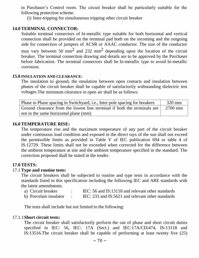
~ 70 ~
in Purchaser‟s Control room. The circuit breaker shall be particularly suitable for the
following protection scheme.
(i) Inter-tripping for simultaneous tripping other circuit breaker
14.0 TERMINAL CONNECTOR:
Suitable terminal connectors of bi-metallic type suitable for both horizontal and vertical
connection shall be provided on the terminal pad both on the incoming and the outgoing
side for connection of jumpers of ACSR or AAAC conductor. The size of the conductor
may vary between 50 mm2 and 232 mm2 depending upon the location of the circuit
breaker. The terminal connection drawing and details are to be approved by the Purchaser
before fabrication. The terminal connectors shall be bi-metallic type to avoid bi-metallic
corrosion.
15.0 INSULATION AND CLEARANCE:
The insulation to ground, the insulation between open contacts and insulation between
phases of the circuit breaker shall be capable of satisfactorily withstanding dielectric test
voltages.The minimum clearance in open air shall be as follows:
Phase to Phase spacing in Switchyard, i.e., Inter pole spacing for breakers 320 mm
Ground clearance from the lowest line terminal if both the terminals are
not in the same horizontal plane (mm)
2700 mm
16.0 TEMPERATURE RISE:
The temperature rise and the maximum temperature of any part of the circuit breaker
under continuous load condition and exposed in the direct rays of the sun shall not exceed
the permissible limits as provided in Table V of IEC publication 694 or table 4 of
IS:12729. These limits shall not be exceeded when corrected for the difference between
the ambient temperature at site and the ambient temperature specified in the standard. The
correction proposed shall be stated in the tender.
17.0 TESTS:
17.1 Type and routine tests:
The circuit breakers shall be subjected to routine and type tests in accordance with the
standards listed in this specification including the following IEC and ARE standards with
the latest amendments.
a) Circuit breaker : IEC: 56 and IS:13118 and relevant other standards
b) Porcelain insulator : IEC: 233 and IS:5621 and relevant other standards
The tests shall include but not limited to the following:
17.1.1 Short circuit tests:
The circuit breaker shall satisfactorily perform the out of phase and short circuit duties
specified in IEC: 56, IEC: 17A (Sect.) and IEC:17A/CD/474, IS-13118 and
IS:13516.The circuit breaker shall be capable of performing at least twenty five (25)

~ 71 ~
open operations at the rated short circuit current before maintenance or inspection is
required.
17.1.2 Capacitive current switching:
Capacitive switching tests shall be performed in accordance with IEC:56 or IS:13118
and IEC:17A/CD/474 at 1.3U preferably by direct test method or alternatively using
synthetic method to IEC:427 or IS:13516. The test circuits shall simulate the most
onerous site conditions.
17.1.3 Reactor Switching:
In addition to the capacitive current switching tests to IEC: 56 or IS: 13118
and IEC:17A/CD/474, the circuit breakers shall be tested for shunt reactor switching in
accordance with IEC:1233, Examination of the interrupter after the tests shall not show
any evidence of surface tracking or erosion of contracts.
17.1.4 Dielectric tests:
At zero gauge loss of vacuum inside the interrupter chamber, the open contracts shall
withstand continuously, the rated phase to ground voltage and it shall be possible to
break normal current in these conditions. During the dielectric type tests, no flashover
external or internal shall be acceptable.
The circuit breakers shall be subjected to a power frequency AC voltage test for one
minute in dry and wet conditions and there shall be no external flash over to earth.
17.1.5 Mechanical endurance:
In addition to the requirements of IEC: 56, an extended mechanical endurance test is
required to show that the circuit breaker is capable of at least 10,000 operations at no
load in accordance with IEC: 17A/474/CD. Between the specified test series in IEC:
17A/474/CD, some maintenance such as lubrication and mechanical adjustment is
allowed and shall be performed in accordance with manufacturer‟s instruction. Change
of contract is not permitted.
17.1.6 Low current switching:
The circuit breakers shall produce very low over voltage (<2.0 pu) on all switching
circuits inductive current including reactor switching to IEC-1233 and capacitive current
switching to IEC:17A (Secretariat) 438 and IEC 17A/CD/474 the circuit breaker shall be
re-ignition or re- strike free for all duties.
17.1.7 Duty requirement tests:
Apart from auto-reclosing and the other duties mentioned above, the breakers shall be
able to perform the following duties for which type tests are to be conducted as
per IEC:56 or IS:13118.
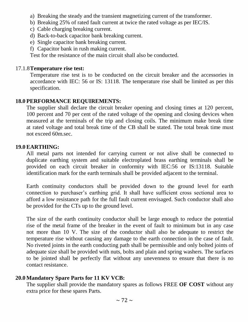
~ 72 ~
a) Breaking the steady and the transient magnetizing current of the transformer.
b) Breaking 25% of rated fault current at twice the rated voltage as per IEC/IS.
c) Cable charging breaking current.
d) Back-to-back capacitor bank breaking current.
e) Single capacitor bank breaking current.
f) Capacitor bank in rush making current.
Test for the resistance of the main circuit shall also be conducted.
17.1.8 Temperature rise test:
Temperature rise test is to be conducted on the circuit breaker and the accessories in
accordance with IEC: 56 or IS: 13118. The temperature rise shall be limited as per this
specification.
18.0 PERFORMANCE REQUIREMENTS:
The supplier shall declare the circuit breaker opening and closing times at 120 percent,
100 percent and 70 per cent of the rated voltage of the opening and closing devices when
measured at the terminals of the trip and closing coils. The minimum make break time
at rated voltage and total break time of the CB shall be stated. The total break time must
not exceed 60m.sec.
19.0 EARTHING:
All metal parts not intended for carrying current or not alive shall be connected to
duplicate earthing system and suitable electroplated brass earthing terminals shall be
provided on each circuit breaker in conformity with IEC:56 or IS:13118. Suitable
identification mark for the earth terminals shall be provided adjacent to the terminal.
Earth continuity conductors shall be provided down to the ground level for earth
connection to purchaser‟s earthing grid. It shall have sufficient cross sectional area to
afford a low resistance path for the full fault current envisaged. Such conductor shall also
be provided for the CTs up to the ground level.
The size of the earth continuity conductor shall be large enough to reduce the potential
rise of the metal frame of the breaker in the event of fault to minimum but in any case
not more than 10 V. The size of the conductor shall also be adequate to restrict the
temperature rise without causing any damage to the earth connection in the case of fault.
No riveted joints in the earth conducting path shall be permissible and only bolted joints of
adequate size shall be provided with nuts, bolts and plain and spring washers. The surfaces
to be jointed shall be perfectly flat without any unevenness to ensure that there is no
contact resistance.
20.0 Mandatory Spare Parts for 11 KV VCB:
The supplier shall provide the mandatory spares as follows FREE OF COST without any
extra price for these spares Parts.

~ 73 ~
Sl.
No.
Description Quantity
1. Complete pole assembly of the circuit breaker 4
2. Vacuum interrupter bottle (for vacuum type only) 4
3. Tripping coils 6
4. Closing coils 6
5. Insulated drive rod 6
6. Spring charging motor 4
7. Set of spring charging limit switches 4
8. Set for gaskets complete for one circuit breaker 4
9. Upper Housing assembly 4
10. Lower Housing assembly 4
CHECK LIST OF THE TENDER ENQUIRY

~ 74 ~
Sl.No. Document Page No.*
1 EMD (Draft / BG) Y/N
2 Cost of Tender Document Y/N
3 Forwarding Letter of the firm Y/N
4 Quantity Offered in forwarding letter Y/N
5 Authorized Signatory Y/N
6 POA/Board resolution for Authorized
Signatory Y/N
7 Duly signed Tender Documents Y/N
8 MOA & AOA Y/N
9 ITCC/STCC/VTCC Y/N
10 A copy of PAN / TIN no. of Firm Y/N
11 Annexure – I Y/N
12 Annexure – II Y/N
13 Annexure –IV (G.T.P) Y/N
14
Annexure-V, Price Bid (This shall be
submitted in a double sealed envelope
separately)
Y/N
15 Annexure-VI (A),Technical Deviation Sheet Y/N
16 Annexure-VI (B),Commercial Deviation
Sheet Y/N
17 Annexure-VII ( Format for Consortium
Agreement) Y/N
18 Annexure-VIII, (FORM OF POWER OF
ATTORNEY FOR CONSORTIUM) Y/N
19 Annexure-IX (Self Declaration Form) Y/N
20 Annexure XI, Past Supply Format Y/N
21 User’s performance certificate Y/N
22 Type Test Report Y/N

~ 75 ~
23 Any other document(s) Y/N
*All the documents should be having running page number e,g say if the total
documents have 50 pages, the first document should be page numbered as 01
and the last document should be page numbered as 50.
Signature of the Tenderer with seal

~ 76 ~
SECTION – V
LIST OF ANNEXURES
(SCHEDULES AND FORMATS)

~ 77 ~
TENDER NOTICE NO: WESCO / CAPEX/ 33 KV & 11 KV VCB /55 Date: 03.11.2014
Annexure – I
ABSTRACT OF GENERAL TERMS AND CONDITIONS
(For supply of 33 & 11KV VCB with CT & CR Panel) Tender Specification No:- ---------------------------------------
1. Name of the material and Quantity offer :-
2.Whether the bidder is a Manufacturer & furnished relevant documents
( Factory Registration Documents ): Yes /
No
3.Required Cost of Tender Furnished ( M.R / Bank Draft Details)-------------------------------------------------
4.Required Earnest Money Furnished:- Bank Draft /BG Details to be furnished) ------------------------------------------
5.Whether Type test certificates for the offered material conducted within last
5 years enclosed with the bid: Yes / No
6.Manufacturer‟s past supply experience
including user‟s certificate furnished or not: - Yes / No
7.Audited annual reports along with Profit & Loss Accounts
for the last 5 years furnished or not: Yes / No
8.Deviation to the specification , if any furnished
as per format at Annexure VI ( A) & VI (B) ):- Yes / No
9.Whether agreed to WESCO‟s Delivery schedule: Yes / No
If agreed, a) Date of commencement
b) Rate of delivery per month
10.Whether agreed to WESCO‟s Guarantee clause :- Yes / No
11.Whether agreed for 180 days‟ validity period of Prices Yes / No
12.Whether the Prices are FIRM? Yes / No
13.Whether agreed to furnish security deposit in shape of
B.G. encashable at Burla/Sambalpur in case his tender is successful Yes / No
14.Whether agreed to stipulated penalty for delayed delivery: - Yes / No
15.Whether agreed to WESCO‟s standard terms of payment
(Clause-14 of Section III): Yes / No
16. Whether agree to WESCO Inspection & testing Clause Yes / No
17.Valid ITCC & STCC /VTCC furnished or not: Yes / No
18.Address with the e-mail for correspondence & contacting person with mobile no to be furnished
----------------------
Signature of the bidder
With seal of company This form is to be duly filled up & ink signed by the Bidder along with seal & submitted along with the
Part-I of tender. The bidder has to quote quantity offered at Sl.No-1.

~ 78 ~
TENDER NOTICE NO: WESCO / CAPEX/ 33 KV & 11 KV VCB /55 Date: 03.11.2014
Annexure – II DECLARATION FORM
To
Sir, Having examined the above specifications together with the Tender terms and conditions
referred to therein.
1. I / we the undersigned do hereby offer to supply the materials covered thereon in
complete shape in all respects as per the rules entered in the attached contract schedule of
prices in the tender.
2. I / we do hereby undertake to have the materials delivered within the time specified in the
tender.
3. I / we do hereby guarantee the technical particulars given in the tender supported with
necessary reports from concerned authorities.
4. I / we do hereby certify to have furnished a copy of the tender specifications by remitting
Cash/ Demand draft & this has been duly acknowledged by you in your letter
No……………..Dt……………….
5. I / we do hereby agree to furnish the composite Bank Guarantee in the manner specified /
acceptable by THE <PURCHASER>& for the sum as applicable to me / us as per clause
No.23 in Annexure-III(A) of this specification within fifteen days of issue of Letter of
intent / Purchase Order, in the event of Purchase order being decided in my / us favour ,
failing which I / we clearly understand that the said LOI / P.O. shall be liable to be
withdrawn by the Purchaser.
Signed this __________ Day of ___________ 20____
Yours faithfully,
(Signature of Bidder with Seal)
(This form should be duly filled up & signed by the bidder & submitted along with the original
copy of the bid)

~ 79 ~
TENDER NOTICE NO: WESCO / CAPEX/ 33 KV & 11 KV VCB /55 Date: 03.11.2014
ANNEXURE – III
PROFORMA FOR COMPOSITE BANK GUARANTEE FOR SECURITY
DEPOSIT, PAYMENT AND PERFORMANCE
This Guarantee Bond is executed this ___ day of ___ by us the __________ Bank at _______
P.O._____ P.S. _______ Dist ________ State __________
(Indicate designation of Purchaser)
Whereas as Western Electricity Supply Company of Odisha Ltd.(WESCO) Regd. Office: N
1/22, IRC Village, Nayapalli, Bhubaneswar – 751015 registered under the Company Act 1956
(here in after called “the Purchaser”) has placed Purchase Order No._________
Dt.___________ (hereinafter called “the Agreement”) with M/s_________________
(hereinafter called “the Contractor”) for supply of ________________ (name of the material)
and whereas WESCO has agreed (1) to exempt the Contractor from making payment of
security deposit, (2) to release 100% payment of the cost of materials as per the said agreement
and (3) to exempt from performance guarantee on furnishing by the Contractor to the WESCO
a composite Bank Guarantee of the value of 10% (ten percent) of the Contract price of the said
Agreement.
1. Now, therefore, in consideration of WESCO having agreed (1) to exempt the Contractor for
making payment of security deposit, (2) to release 100% payment to the Contractor and (3)
to exempt from furnishing performance guarantee in terms of the said Agreement as
aforesaid, we the ___________ Bank, Address ___________ (code No. ____) (hereinafter
referred to as “the Bank”) do hereby undertake to pay to the WESCO an amount not
exceeding Rs.________ (Rupees ___________) only against any loss or damage caused to
or suffered by WESCO by reason of any breach by the said Contractor(s) of any of the
terms or conditions contained in the said Agreement.
2. We, the_____ Bank do hereby undertake to pay the amounts due and payable under the
guarantee without any demur, merely on a demand WESCO stating that the amount claimed
is due by way of loss or damage caused to or suffered by WESCO by reason of any breach
by the said Contractor(s) of any of the terms or conditions contained in the said Agreement
or by the reason of any breach by the said Contractor‟s failure to perform the said
Agreement. Any such demand made on the Bank shall be conclusive as regards the amount
due and payable by the Bank under this Guarantee. However, our liability under this
guarantee shall be restricted to an amount not exceeding Rs.______ (Rupees ______ ) only.
3. We, the ________________________ Bank also undertake to pay to WESCO any money
so demanded not withstanding any dispute or dispute raised by the Contractor(s) in any suit

~ 80 ~
or proceeding instituted/ pending before any court or Tribunal relating thereto our liability
under this Agreement being absolute and irrevocable.
The payment so made by us under this bond shall be valid discharge of our liability for
payment there under and the Contractor(s) shall have no claim against us for making such
payment.
4. We, the ____________ Bank further agree that the guarantee herein contain shall remain in
full force and affect during the period that would be taken for the performance of the said
Agreement and it shall continue to remain in force endorsable till all the dues of WESCO
under by virtue of the said Agreement have been fully paid and its claim satisfied or
discharged or till WESCO certifies that the terms and conditions of the said Agreement
have been fully and properly carried out by the said Contractor(s) and accordingly discharge
this guarantee and will not be revoked by us during the validity of the guarantee period.
Unless a demand or claim under this guarantee is made on us or with_____________
____________________________________ (Local Bank Name, address and code No.)
_________________________________________________, Burla / Sambalpur in writing
on or before __________________ (date) we shall be discharged from all liability under
this guarantee thereafter.
5. We, the _________________________ Bank further agree that WESCO shall have the
fullest liberty without our consent and without affecting in any manner our obligations
hereunder to vary any of the terms and conditions of the said Agreement or to extend time
of performance by the said Contractor(s) and we shall not be relieved from our liability by
reason of any such variation or extension being granted to the said Contractor(s) or for any
forbearance act or omission on part of WESCO or any indulgence by WESCO to the said
Contractor(s) or by any such matter or thing whatsoever which under the law relating to
sureties would but for this provisions have effect of so relieving us.
6. The Guarantee will not be discharged due to change in the name, style and constitution of
the Bank and or Contractor(s).
7. We, the _________________________ Bank lastly undertake not to revoke this Guarantee
during its currency except with the previous consent of WESCO in writing.
Dated ___________ the __________ day of Two thousand _________.
Notwithstanding anything contained herein above.
Our liability under this Bank Guarantee shall not exceed Rs.______________ (Rupees
_______ ________________________________________ ) only.
The Bank Guarantee shall be valid up to _____________________ only.

~ 81 ~
We or our Bank at Burla / Sambalpur (Name & Address of the Local Bank) are liable to pay
the guaranteed amount depending on the filing of claim and any part thereof under this
Bank Guarantee only and only if you serve upon us or our local Bank at Burla / Sambalpur
a written claim or demand and received by us or by Local Branch at Burla / Sambalpur on
or before Dt.__________ otherwise bank shall be discharged of all liabilities under this
guarantee thereafter.
For _____________________________________
(Indicate the name of the Bank)
N.B.:
1. Name of the Contractor:
2. No. & date of the Purchase order / agreement:
3. Amount of P.O.:
4. Name of Materials:
5. Name of the Bank:
6. Amount of the Bank Guarantee:
7. Name, Address and Code No. of the Local Branch:
8. Validity period or date up to which the agreement is valid:
9. Signature of the Constituent Authority of the Bank with seal:
10. Name & addresses of the Witnesses with signature:
11. The Bank Guarantee shall be accepted only after getting confirmation from the
respective Banks.
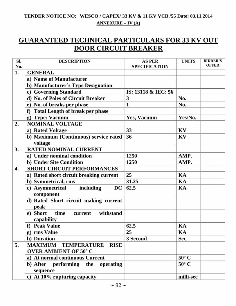
~ 82 ~
TENDER NOTICE NO: WESCO / CAPEX/ 33 KV & 11 KV VCB /55 Date: 03.11.2014
ANNEXURE – IV (A)
GUARANTEED TECHNICAL PARTICULARS FOR 33 KV OUT
DOOR CIRCUIT BREAKER Sl.
No.
DESCRIPTION AS PER
SPECIFICATION
UNITS BIDDER’S
OFFER
1. GENERAL
a) Name of Manufacturer
b) Manufacturer’s Type Designation
c) Governing Standard IS: 13118 & IEC: 56
d) No. of Poles of Circuit Breaker 3 No.
e) No. of breaks per phase 1 No.
f) Total Length of break per phase
g) Type: Vacuum Yes, Vacuum Yes/No.
2. NOMINAL VOLTAGE
a) Rated Voltage 33 KV
b) Maximum (Continuous) service rated
voltage
36 KV
3. RATED NOMINAL CURRENT
a) Under nominal condition 1250 AMP.
b) Under Site Condition 1250 AMP.
4. SHORT CIRCUIT PERFORMANCES
a) Rated short circuit breaking current 25 KA
b) Symmetrical, rms 31.25 KA
c) Asymmetrical including DC
component
62.5 KA
d) Rated Short circuit making current
peak
e) Short time current withstand
capability
f) Peak Value 62.5 KA
g) rms Value 25 KA
h) Duration 3 Second Sec
5. MAXIMUM TEMPERATURE RISE
OVER AMBIENT OF 50º C
a) At normal continuous Current 50º C
b) After performing the operating
sequence
50º C
c) At 10% rupturing capacity milli-sec

~ 83 ~
6. Make & Break Time
Total Break Time
a) At 10% rupturing capacity 60 milli-sec
b) At rated rupturing capacity 60 milli
c) Arcing time at rated breaking current 60 milli
d) Make time from giving close
command
60 milli
e) Minimum reclose time at full rated
interrupting capacity from trip coil
enrgisation
f) Minimum dead time for 3 phase
reclosing
milli-sec
g) Circuit breaker opening time
(i) At 125% of rated voltage of
opening device
60 milli-sec
(ii) At 100% of rated voltage of
opening device
60 milli-sec
(iii) At 70% of rated voltage of opening
device
60 milli-sec
h) Circuit Breaker closing time
(i) At 125% of rated voltage of
opening device
60 milli-sec
(ii) At 100% of rated voltage of
opening device
60 milli-sec
(iii) At 70% of rated voltage of opening
device
60 milli-sec
7. RESTRIKING VOLTAGE FOR 100%
RATED CAPACITY
a) Amplitude Factor KV
b) Phase Factor KV
c) Natural Frequency KHz
d) Rate of rise of recovery voltage KV/µs
8. RATED INSULATION LEVEL
a) Dry & Wet Power Frequency
withstand Test voltage (rms) for 1
min.
(i) Between live terminals and
grounded objects
70 KV
(ii) Between terminals with breaker
contacts open
70 KV
b) 1.2 / 50µsec full wave impulse
withstand voltage + ve & - ve
polarity (peak)
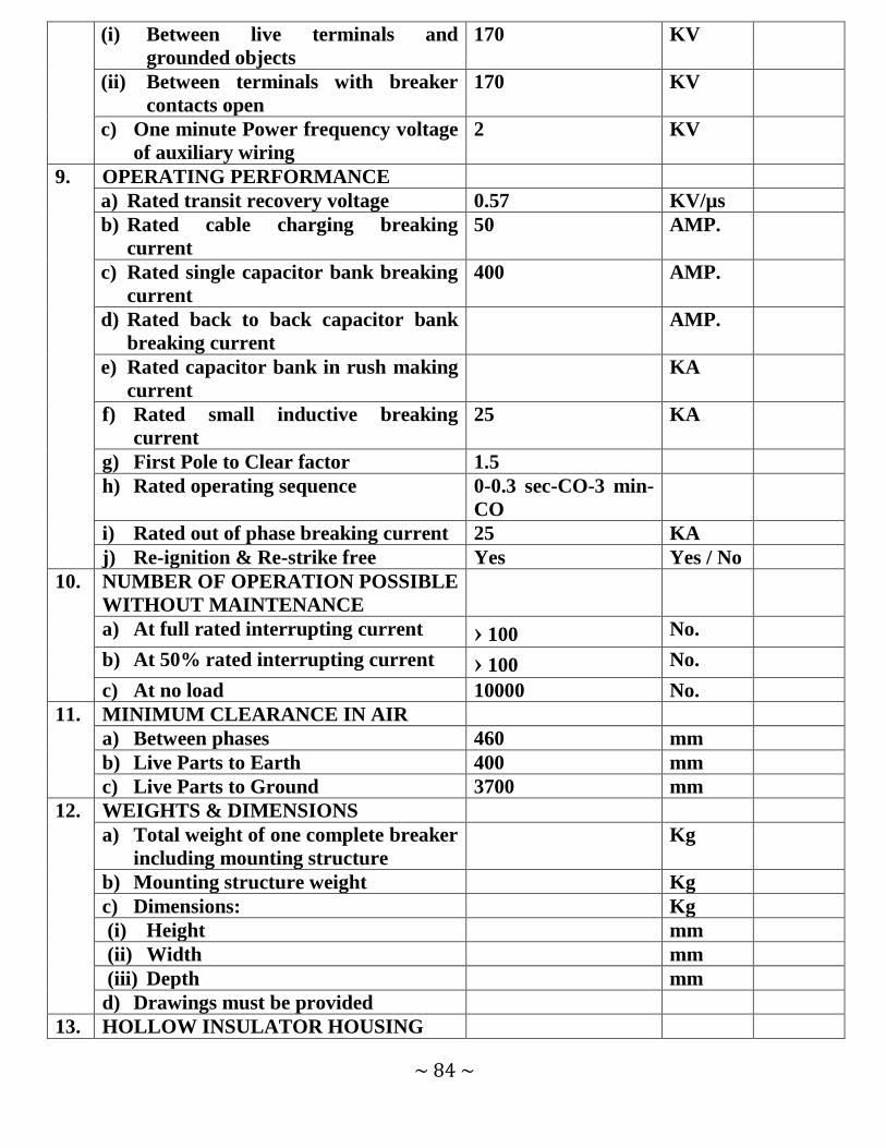
~ 84 ~
(i) Between live terminals and
grounded objects
170 KV
(ii) Between terminals with breaker
contacts open
170 KV
c) One minute Power frequency voltage
of auxiliary wiring
2 KV
9. OPERATING PERFORMANCE
a) Rated transit recovery voltage 0.57 KV/µs
b) Rated cable charging breaking
current
50 AMP.
c) Rated single capacitor bank breaking
current
400 AMP.
d) Rated back to back capacitor bank
breaking current
AMP.
e) Rated capacitor bank in rush making
current
KA
f) Rated small inductive breaking
current
25 KA
g) First Pole to Clear factor 1.5
h) Rated operating sequence 0-0.3 sec-CO-3 min-
CO
i) Rated out of phase breaking current 25 KA
j) Re-ignition & Re-strike free Yes Yes / No
10. NUMBER OF OPERATION POSSIBLE
WITHOUT MAINTENANCE
a) At full rated interrupting current › 100 No.
b) At 50% rated interrupting current › 100 No.
c) At no load 10000 No.
11. MINIMUM CLEARANCE IN AIR
a) Between phases 460 mm
b) Live Parts to Earth 400 mm
c) Live Parts to Ground 3700 mm
12. WEIGHTS & DIMENSIONS
a) Total weight of one complete breaker
including mounting structure
Kg
b) Mounting structure weight Kg
c) Dimensions: Kg
(i) Height mm
(ii) Width mm
(iii) Depth mm
d) Drawings must be provided
13. HOLLOW INSULATOR HOUSING

~ 85 ~
a) Type & Make of Insulator
b) Power frequency withstand test
voltage for one minute
(i) Dry: 70 KV
(ii) Wet 70 KV
c) Flash Over Value
(i) Dry 135 KV
(ii) Wet 95 KV
d) 1.2 / 50 Impulse voltage withstand
capability
(i) Positive Polarity 170 KVp
(ii) Negative Polarity 170 KVp
e) Total Creepage Distance 900 mm
f) Protected Creepage Distance 450 mm
g) Weight of assembled housing Kg
h) Corona shield provided or not Yes
14. SUPPORT INSULATOR
a) Type & Make of Insulator
b) Power frequency withstand test
voltage for one minute
(i) Dry 70 KV
(ii) Wet 70 KV
i) Flash Over Value
(iii) Dry 135 KV
(iv) Wet 95 KV
j) 1.2 / 50 Impulse voltage withstand
capability
(iii) Positive Polarity 170 KVp
(iv) Negative Polarity 170 KVp
k) Total Creepage Distance 900 mm
l) Protected Creepage Distance 450 mm
m) Weight of assembled housing Kg
n) Corona shield provided or not Yes
15. CONTACTS
a) Type of main contacts Butt
b) Type of Auxiliary
c) Materials of Auxiliary Contacts Silver plated brass
d) Type of platings, if any Silver
e) Thickness of plating 20 Micron
f) Contact pressure
g) No. of auxiliary contacts provided 6 NO + 6 NC
h) Those closed when breakers is
closed
6 Nos.

~ 86 ~
i) Those open when breaker is closed 6 Nos.
j) Those adjustable
16. OPERATING MECHANISM
a) Opening Type Shunt Type
b) Closing Type Motor / Manual
Spring Charge,
Shunt / Magnetic
actuator operation
c) Force applied by charged spring
for closing
d) Time taken by motor for charging
the spring from fully discharged to
fully charged position
‹ 30
e) Full sequence of operation 0-0.3 Sec-CO-3 min-
CO
f) Whether limit switches are
provided with spring
Yes Yes / No
g) Whether spring limit switches
start & stop the motor
Yes Yes / No
h) Type & materials of spring
employed
i) Whether Trip free Yes
j) Whether anti pumping device
provided
Yes
17. AUXILIARY & CONTROL POWER
SUPPLY
a) Normal auxiliary AC supply
voltage
230 Volt
b) Voltage limits for proper
operation
Volt
(i) Maximum 115% Volt
(ii) Minimum 85% Volt
c) Frequency limits for proper
operation
(i) Maximum +5% Hz
(ii) Minimum -5% Hz
d) For Circuit Breakers:
(i) Normal DC control circuit
voltage
24 Volt
e) Voltage limits for proper
operation
(i) Maximum 120% Volt
(ii) Minimum 70% Volt

~ 87 ~
f) Power required for trip coil 300 Watt
g) Power required for closing coil 300 Watt
18. LOCAL CONTROL PANEL
a) Material
b) Degree of Protection
c) Vermin proof provisions Yes Yes/No
d) Weather proof provision Yes Yes/No
e) Dust proof provision Yes Yes/No
f) Ventilation provision Yes Yes/No
g) Thickness of sheet materials used 3 mm
h) Overall Dimensions mm
i) Total weight Kg
j) Mounting
19. TERMINAL CONNECTOR
a) Material
b) Bi-metallic or not Yes
c) Weight
d) Dimension
e) Size & Type of Conductor it can
accommodate
100 sq mm
f) Terminal pads silver plated or not Yes
g) Thickness of Silver plating micron
20. CORROSSION PREVENTION
SYSTEM FOR CIRCUIT BREAKER &
CONTROL CABINET
Preferably
galvanized
a) Surface Preparation
b) Rust inhibition
c) Zinc thickness / Paint thickness micron
d) Treatment of fasteners
21. CORROSSION PREVENTION
SYSTEM FOR SUPPORT
STRUCTURE
Hot Dip Galvanized
a) Surface preparation
e) Rust inhibition
f) Zinc thickness
g) Treatment of fasteners
22. VACUUM CIRCUIT BREAKER
SEALING
Hermetically Sealed
a) Degree of protection of Circuit
Breaker pole enclosure (IEC 529,
IS: 13947)
b) Method of sealing the circuit
breaker pole enclosure

~ 88 ~
GUARANTEED TECHNICAL PARTICULARS FOR 33 KV
CURRENT TRANSFORMER
Sl.
No.
DESCRIPTION AS PER
SPECIFICATION
UNITS BIDDER’S
OFFER
Make of Manufacturer
Make & Type of Current Transformer
CURRENT TRANSFORMER RATIO: 400-200-100 / 1-1 Amp.
1. Core: 1
a) Burden 15 VA
b) Accuracy Class 0.5
c) Saturation Factor
d) Instrument Security Factor ‹ 5
e) Accuracy Limit Factor
f) Knee Point Voltage
g) Magnetizing current at Vk / 2 milliamp
h) Secondary Resistance Rct ≤ 2 at 75º C Ω
2. Core: 2
a) Burden 15 VA
b) Accuracy Class 5P
c) Saturation Factor
d) Instrument Security Factor
e) Accuracy Limit Factor 20
4. Short time current rating 25
5. Time 3 sec
6. Impulse voltage withstand level 170 KVp
7. Power frequency voltage withstand level
a) Primary Winding 70 KV
b) Secondary Winding 3 KV
8. Specification of Oil IS: 335
9. Quantity of Oil ltr.
10. Creepage Distance 900 mm
11. Protected Creepage Distance 450 mm
12. Weight of CT complete with oil Kg
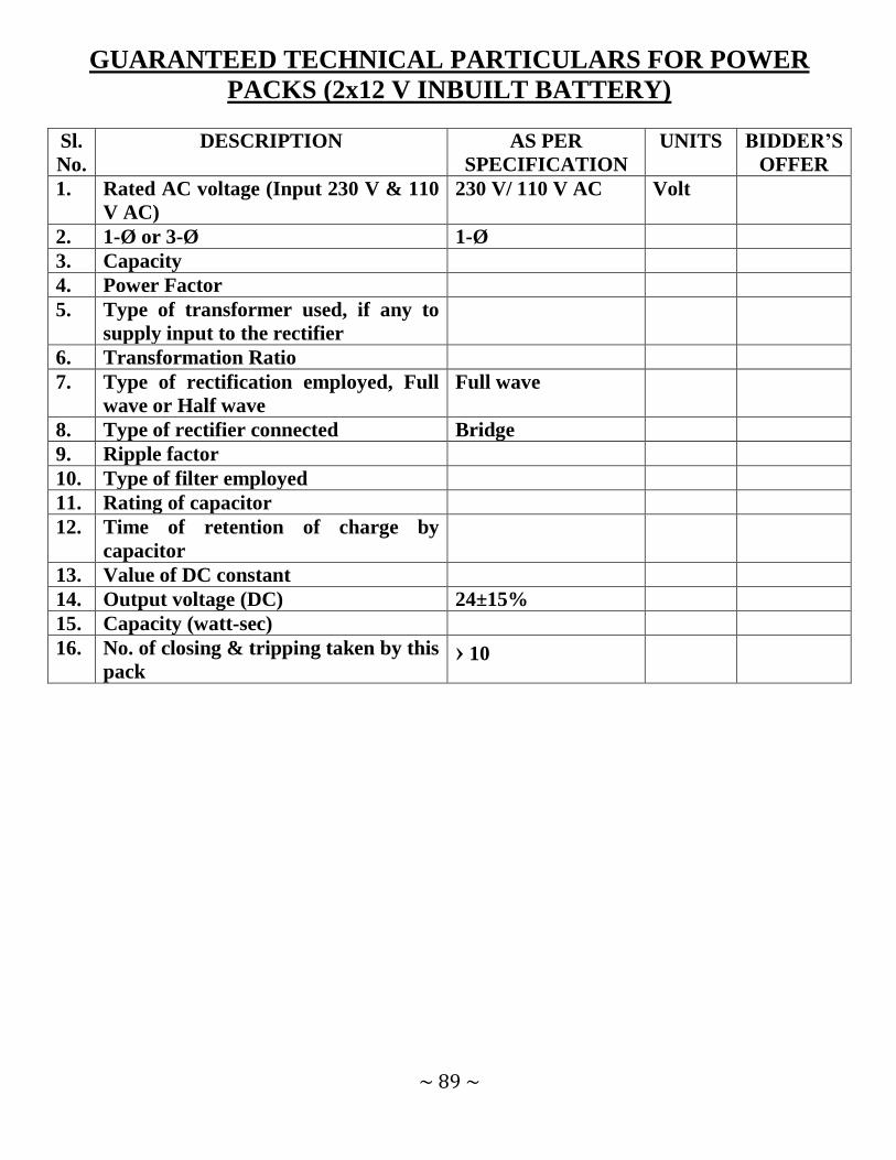
~ 89 ~
GUARANTEED TECHNICAL PARTICULARS FOR POWER
PACKS (2x12 V INBUILT BATTERY)
Sl.
No.
DESCRIPTION AS PER
SPECIFICATION
UNITS BIDDER’S
OFFER
1. Rated AC voltage (Input 230 V & 110
V AC)
230 V/ 110 V AC Volt
2. 1-Ø or 3-Ø 1-Ø
3. Capacity
4. Power Factor
5. Type of transformer used, if any to
supply input to the rectifier
6. Transformation Ratio
7. Type of rectification employed, Full
wave or Half wave
Full wave
8. Type of rectifier connected Bridge
9. Ripple factor
10. Type of filter employed
11. Rating of capacitor
12. Time of retention of charge by
capacitor
13. Value of DC constant
14. Output voltage (DC) 24±15%
15. Capacity (watt-sec)
16. No. of closing & tripping taken by this
pack › 10

~ 90 ~
TENDER NOTICE NO: WESCO / CAPEX/ 33 KV & 11 KV VCB /55 Date: 03.11.2014
ANNEXURE – IV (B)
GUARANTEED TECHNICAL PARTICULARS FOR 11 KV OUT
DOOR CIRCUIT BREAKER
Sl.
No.
DESCRIPTION AS PER
SPECIFICATION
UNITS BIDDER’S
OFFER
1. GENERAL
a) Name of Manufacturer
b) Manufacturer’s Type Designation Out Door Type
c) Governing Standard IS: 13118 & IEC:
62271-100
d) No. of Poles of Circuit Breaker 3 No.
e) No. of breaks per phase 1 No.
f) Total Length of break per phase
g) Type: Vacuum Vacuum Yes/No.
2. NOMINAL VOLTAGE
a) Rated Voltage 11 KV
b) Maximum (Continuous) service rated
voltage
12 KV
3. RATED NOMINAL CURRENT
a) Under nominal condition 800 AMP.
b) Under Site Condition 800 AMP.
4. SHORT CIRCUIT PERFORMANCES
a) Rated short circuit breaking current
b) Symmetrical, rms 25 KA
c) Asymmetrical including DC
component
30 KA
d) Rated Short circuit making current
peak
62.5 KA
e) Short time current withstand
capability
f) Peak Value 62.5 KA
g) rms Value 25 KA
h) Duration 3 Sec
5. MAXIMUM TEMPERATURE RISE
OVER AMBIENT OF 50º C
a) At normal continuous Current º C
b) After performing the operating º C

~ 91 ~
sequence
c) At 10% rupturing capacity milli-sec
6. Make & Break Time
Total Break Time
a) At 10% rupturing capacity ‹ 60 milli-sec
b) At rated rupturing capacity ‹ 60 milli
c) Arcing time at rated breaking
current
15 milli
d) Make time from giving close
command ‹ 60 milli
e) Minimum reclose time at full rated
interrupting capacity from trip coil
enrgisation
300
f) Minimum dead time for 3 phase
reclosing
milli-sec
g) Circuit breaker opening time
(i) At 125% of rated voltage of
opening device ‹ 60 milli-sec
(ii) At 100% of rated voltage of
opening device ‹ 60 milli-sec
(iii) At 70% of rated voltage of opening
device ‹ 60 milli-sec
7. RESTRIKING VOLTAGE FOR 100%
RATED CAPACITY
a) Amplitude Factor 62 KV
b) Phase Factor 3 KV
c) Natural Frequency KHz
d) Rate of rise of recovery voltage KV/µs
8. RATED INSULATION LEVEL
a) Dry & Wet Power Frequency
withstand Test voltage (rms) for 1
min.
(i) Between live terminals and
grounded objects
28 KV
(ii) Between terminals with breaker
contacts open
28 KV
b) 1.2 / 50µsec full wave impulse
withstand voltage + ve & - ve
polarity (peak)
(i) Between live terminals and
grounded objects
75 KVp
(ii) Between terminals with breaker
contacts open
75 KVp

~ 92 ~
c) One minute Power frequency voltage
of auxiliary wiring
2 KVp
9. OPERATING PERFORMANCE
a) Rated transit recovery voltage KV/µs
b) Rated cable charging breaking
current
25 AMP.
c) Rated single capacitor bank breaking
current
400 AMP.
d) Rated back to back capacitor bank
breaking current
400 AMP.
e) Rated capacitor bank in rush making
current
20 KA
f) Rated small inductive breaking
current
25 KA
g) First Pole to Clear factor 1.5
h) Rated operating sequence 0-0.3 sec-CO-3 min-
CO
i) Rated out of phase breaking current KA
j) Re-ignition & Re-strike free Yes Yes / No
10. NUMBER OF OPERATION POSSIBLE
WITHOUT MAINTENANCE
a) At full rated interrupting current › 100 No.
b) At 50% rated interrupting current › 100 No.
c) At no load 10000 No.
11. MINIMUM CLEARANCE IN AIR
a) Between phases › 150 mm
b) Live Parts to Earth › 120 mm
c) Live Parts to Ground mm
12. WEIGHTS & DIMENSIONS
a) Total weight of one complete breaker
including mounting structure
Kg
b) Mounting structure weight Kg
c) Dimensions: Kg
(i) Height mm
(ii) Width mm
(iii) Depth mm
d) Drawings must be provided Yes / No
13. HOLLOW INSULATOR HOUSING
a) Type & Make of Insulator
b) Power frequency withstand test
voltage for one minute
(i) Dry: 28 KV
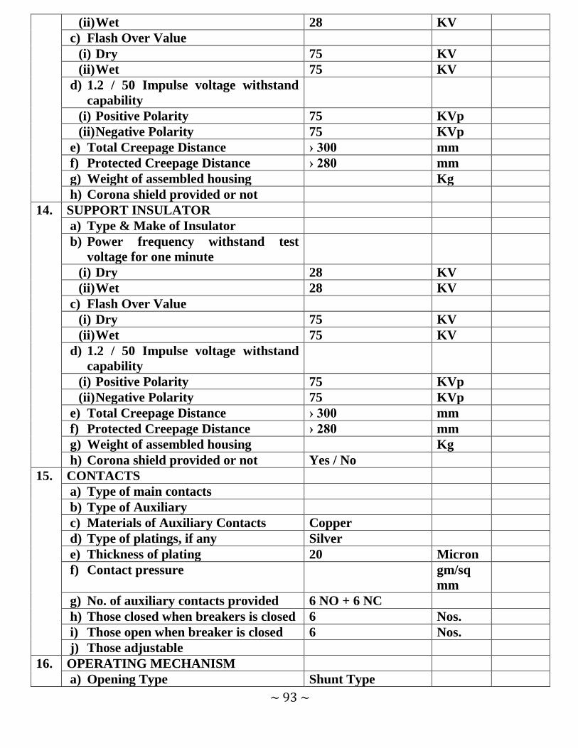
~ 93 ~
(ii) Wet 28 KV
c) Flash Over Value
(i) Dry 75 KV
(ii) Wet 75 KV
d) 1.2 / 50 Impulse voltage withstand
capability
(i) Positive Polarity 75 KVp
(ii) Negative Polarity 75 KVp
e) Total Creepage Distance › 300 mm
f) Protected Creepage Distance › 280 mm
g) Weight of assembled housing Kg
h) Corona shield provided or not
14. SUPPORT INSULATOR
a) Type & Make of Insulator
b) Power frequency withstand test
voltage for one minute
(i) Dry 28 KV
(ii) Wet 28 KV
c) Flash Over Value
(i) Dry 75 KV
(ii) Wet 75 KV
d) 1.2 / 50 Impulse voltage withstand
capability
(i) Positive Polarity 75 KVp
(ii) Negative Polarity 75 KVp
e) Total Creepage Distance › 300 mm
f) Protected Creepage Distance › 280 mm
g) Weight of assembled housing Kg
h) Corona shield provided or not Yes / No
15. CONTACTS
a) Type of main contacts
b) Type of Auxiliary
c) Materials of Auxiliary Contacts Copper
d) Type of platings, if any Silver
e) Thickness of plating 20 Micron
f) Contact pressure gm/sq
mm
g) No. of auxiliary contacts provided 6 NO + 6 NC
h) Those closed when breakers is closed 6 Nos.
i) Those open when breaker is closed 6 Nos.
j) Those adjustable
16. OPERATING MECHANISM
a) Opening Type Shunt Type

~ 94 ~
b) Closing Type Motor / Manual
Spring Charge,
Shunt / Magnetic
actuator operation
c) Force applied by charged spring for
closing
Kg/N
d) Time taken by motor for charging
the spring from fully discharged to
fully charged position
‹ 30 sec
e) Full sequence of operation 0-0.3 Sec-CO-3 min-
CO
f) Whether limit switches are provided
with spring
Yes / No
g) Whether spring limit switches start
& stop the motor
Yes / No
h) Type & materials of spring employed
i) Whether Trip free Yes
j) Whether anti pumping device
provided
Yes
17. AUXILIARY & CONTROL POWER
SUPPLY
a) Normal auxiliary AC supply voltage 230 Volt
b) Voltage limits for proper operation Volt
(i) Maximum 115% Volt
(ii) Minimum 85% Volt
c) Frequency limits for proper
operation
(i) Maximum 105% Hz
(ii) Minimum 95% Hz
d) For Circuit Breakers:
(i) Normal DC control circuit voltage 24 Volt
e) Voltage limits for proper operation
(i) Maximum 120% Volt
(ii) Minimum 70% Volt
f) Power required for trip coil 300 Watt
g) Power required for closing coil 300 Watt
18. LOCAL CONTROL PANEL
a) Material
b) Degree of Protection
c) Vermin proof provisions Yes/No
d) Weather proof provision Yes/No
e) Dust proof provision Yes/No
f) Ventilation provision Yes/No

~ 95 ~
g) Thickness of sheet materials used 3 mm
h) Overall Dimensions mm
i) Total weight Kg
j) Mounting
19. TERMINAL CONNECTOR
a) Material
b) Bi-metallic or not Yes/No
c) Weight
d) Dimension
e) Size & Type of Conductor it can
accommodate
100 sq mm
f) Terminal pads silver plated or not Yes/No
g) Thickness of Silver plating micron
20. CORROSSION PREVENTION
SYSTEM FOR CIRCUIT BREAKER &
CONTROL CABINET
a) Surface Preparation
b) Rust inhibition
c) Zinc thickness / Paint thickness micron
d) Treatment of fasteners
21. CORROSSION PREVENTION
SYSTEM FOR SUPPORT
STRUCTURE
Hot Dip Galvanized
a) Surface preparation
b) Rust inhibition
c) Zinc thickness
d) Treatment of fasteners
22. VACUUM CIRCUIT BREAKER
SEALING
a) Degree of protection of Circuit
Breaker pole enclosure (IEC 529, IS:
13947)
b) Method of sealing the circuit breaker
pole enclosure

~ 96 ~
GUARANTEED TECHNICAL PARTICULARS FOR 11 KV
CURRENT TRANSFORMER
Sl.
No.
DESCRIPTION AS PER
SPECIFICATION
UNITS BIDDER’S
OFFER
Make of Manufacturer
Make & Type of Current Transformer Out Door Type, 1-
Ph, Oil cooled, Dead
Tank
CURRENT TRANSFORMER RATIO: 400-200-100 / 1-1 Amp.
1. Core: 1
i) Burden 15 VA
j) Accuracy Class 0.5
k) Saturation Factor
l) Instrument Security Factor 10
m) Accuracy Limit Factor
2. Core: 2
f) Burden 15 VA
g) Accuracy Class 5P
h) Saturation Factor
i) Instrument Security Factor
j) Accuracy Limit Factor 20
4. Short time current rating 25 KA for 3 sec
5. Impulse voltage withstand level 75 KVp
6. Power frequency voltage withstand level
c) Primary Winding 28 KV
d) Secondary Winding 3 KV
7. Weight of CT complete with oil Kg

~ 97 ~
GUARANTEED TECHNICAL PARTICULARS FOR POWER
PACKS (2x12 V INBUILT BATTERY)
Sl.
No.
DESCRIPTION AS PER
SPECIFICATION
UNITS BIDDER’S
OFFER
1. Rated AC voltage (Input 230 V & 110
V AC)
230 V/ 110 V AC Volt
2. 1-Ø or 3-Ø 1-Ø
3. Capacity
4. Power Factor
5. Type of transformer used, if any to
supply input to the rectifier
6. Transformation Ratio
7. Type of rectification employed, Full
wave or Half wave
Full wave
8. Type of rectifier connected Bridge
9. Ripple factor
10. Type of filter employed
11. Rating of capacitor
12. Time of retention of charge by
capacitor
13. Value of DC constant
14. Output voltage (DC) 24±15%
15. Capacity (watt-sec)
16. No. of closing & tripping taken by this
pack › 10

~ 98 ~
Annexure- V Price Schedule for materials /equipments offered as per TENDER NOTICE
No.: WESCO / CAPEX/ 33KV & 11KV VCB /55 Date: 03.11.2014
WESCO Name of Bidder: ________________________________
Price for each Unit Sl. No. Item Description Unit Quant
ity
Unit
Ex-
Works
Price
(Rs.)
Unit Packing
&
Forwarding
Charges
(Rs.)
Unit
Excise
Duty with
Education
Cess (Rs.)
Unit
Sales
Tax /
VAT
(Rs.)
Unit
freight &
Insurance
and other
local
costs
incidental
to
delivery
(Rs.)
Unit
Entry
Tax
if
any
(Rs.)
Total Unit
Price
Inclusive
of Taxes &
Duties
(Rs.)
Total
Landi
ng
Price
Inclus
ive of
Taxes
&
Dutie
s
(Rs.) 1 2 3 4 5 6 7 8 9 10 11=
(5+6+7+8+9+10)
12= 4 x
11
1. 33 KV VCB
with 2 Core CT
& CR Panel
Set 10
2. 11 KV VCB
with 2 Core CT
& CR Panel
Set 15
Total amount in Words: Rupees ____________________________ only
Signature of Bidder along with Seal & date
Note:
1. Any column left blank shall be treated as NIL / Inclusive of. 2. Unit price under Column-11 is inclusive of all. 3. In case of discrepancy between unit price and total price, the unit price shall prevail over
the total price.

~ 99 ~
ANNEXURE VI (A) TENDER NOTICE No.: WESCO / CAPEX/ 33 KV & 11 KV VCB /55 Date: 03.11.2014
TECHNICAL DEVIATION FORMAT
Clause No. Prescribed as per Tender
Specification
Deviation in the bidder’s offer
Bidder‟s Signature with Seal.
N.B:
The bidder has to mention all technical deviations in his offer which differs from the Technical
Requirement of this Tender in above format. Deviations not mentioned in above format but
mentioned in any other format or in any other part of the offer document shall not be
considered as deviation and the bidder shall be deemed to have accepted our technical
requirement without deviation.

~ 100 ~
ANNEXURE VI (B)
TENDER NOTICE No.: WESCO / CAPEX/ 33 KV & 11 KV VCB /55 Date: 03.11.2014
COMMERCIAL DEVIATION FORMAT
Clause No. Prescribed as per Tender Specification Provided in the bidder’s offer
Bidder’s Signature with Seal
N.B.:
The bidder has to mention all commercial deviations in his offer which differs from the
Commercial Requirement of this Tender in above format. Deviations not mentioned in this
format but mentioned in any other format or in any other part of the offer document shall not
be considered as deviation and the bidder shall be deemed to have accepted our commercial
requirement without deviation.

~ 101 ~
TENDER NOTICE No.: WESCO / CAPEX/ 33 KV & 11 KV VCB /55 Date: 03.11.2014
ANNEXURE – VII
Format for Consortium Agreement (On non-judicial stamp paper of appropriate value to be purchased in the name of executants
companies or as required by the jurisdiction in which executed)
This Consortium Agreement executed on this …………….. day of
……………………Two Thousand………………….. M/s ……………………………..a
Company (SSI Unit) incorporated under the companies Act – 1956
………………………………………and having its registered office at
………………………….(hereinafter called the “Lead Member/First member” which
expression shall include its successors); and
M/s ………………………………….a company (SSI Unit) incorporated under the
Companies Act – 1956 …………………………………….and having its registered office at
…………………(hereinafter called the “Second Member” which expression shall include its
successors)and
M/s. …………………………….……..a company (SSI Unit) incorporated under the
companies Act- 1956…………………………………………………..and having its registered
office at ……………… (hereinafter called the “Fourth Member” which expression shall
include its successors)
The Lead Member/First Member, the Second Member, the Third Member and the Fourth
Member shall collectively hereinafter be called as the “Consortium Members” for the purpose
of submitting a bid proposal to Western Electricity Supply Company of Odisha Ltd. (WESCO)
(Hereinafter referred to as DISCOM) , being a Company incorporated/Constituted under the
Companies Act,1956 having its office at Burla/Sambalpur - 751015, India (hereinafter called
the “Purchaser”) in response to the invitation of bids (hereinafter called as “Tender Notice
No………” Document) Dated …………… for supply of Materials/Equipments (hereinafter
called as “the Transaction”).
WHEREAS Clause-6.1.2 of the Invitation for Bids (IFB),stipulates that Two or more Local
SSI Units having been manufacturers of tender item(s) as per this tender specification,
provided they fulfill the following eligible criteria;
a) They should have legally valid consortium agreement as per the prescribed
format for the purpose of participation in the bidding process. The total no of a
consortium shall be limited to four members.
b) All members of the Consortium should be the eligible manufacturer(s) of the materials /
equipments tendered.
c) Each member should have valid statutory license to use BEE three star or more level
Certification/Type tested report for the tendered materials/equipments conducted within

~ 102 ~
last five years as applicable for the tender.
d) Consortium as a whole shall meet the qualifying norms specified in the tender, they
participate.
e) The lead member of the Consortium should meet at least 50% of the qualifying norms in
respect of the supply experience.
f) Besides the lead member, other member (s) of the Consortium should meet at least
15% of the qualifying norms in respect of the supply experience.
g) All the Consortium member(s) shall authorize the lead partner by submitting a power
of Attorney as per the prescribed format duly signed by the authorized signatories. The
lead partner shall be authorized to receive instructions for and on behalf of all partners
of the Consortium and entire execution of the contract including receipt of payment
exclusively done through the lead partner.
h) The Consortium and its members shall be jointly and severally responsible and be held
liable for the purpose of guaranteed obligation and any other matter as required under
the contract.
i) Any member of the Consortium member(s) shall not be eligible either in an individual
capacity or part of any other consortium to participate in the tender, where the said
consortium participates.
j) The prescribed formats for Consortium Agreement (Annexure – VII) and Power of
Attorney (Annexure – VIII) are provided in the tender specification as enclosures.
AND WHEREAS the members of the Consortium strictly comply the eligible criteria of the
CLAUSE -6.1.2 of the Invitation for Bids (IFB) as stipulated above, AND WHEREAS bid has
been proposed to be submitted to the purchaser vide bid by Lead Member based on this
CONSORTIUM agreement between all the members, signed by all the members.
NOW THIS INDENTURE WITNESSETH AS UNDER:
In consideration of the above premises, in the event of the selection of Consortium as
successful bidder, all the Parties to this Consortium Agreement do hereby agree abide
themselves as follows:
1. M/s ……………………….shall act as Lead Member for and on behalf of Consortium
Members. The said Consortium members further declare and confirm that they shall
jointly and severally be bound and shall be fully responsible to the Purchaser for the
design, manufacture, supply, and successful performance of the materials /equipment,
obligations under the supply contract under Agreement(s) submitted/executed by the
Lead Member.
2. Despite any breach by the Lead Member or other member(s) of the CONSORTIUM
agreement, the Member(s) do hereby agree and undertake to ensure full and effectual an
successful performance of the contract with Purchaser and to carry out all the
obligations and responsibilities under the said Contract in accordance with the
requirements of the Contract.

~ 103 ~
3. If the Purchaser suffers any loss or damage on account of any breach of the Contract or
any shortfall in the performance in meeting the performance guaranteed as per the
specification in terms of the Contract, the Member(s) of these presents undertake to
promptly make such loss or damage caused to the purchaser, on its demand without any
demur. It shall not be necessary or obligatory for the purchaser to proceed against Lead
member to these presents before proceeding against or dealing with the other
members. The obligation of each of the member is absolute and not independent of the
consortium or any member.
4. The financial liability of the members of this CONSORTIUM agreement to the
Purchaser, with respect to any of the claims arising out of the performance or non-
performance of the obligations set forth in the said CONSORTIUM agreement, read in
conjunction with relevant conditions of the contract shall, however, not be limited in
anyway so as to restrict or limit the liabilities of any of the members of the
CONSORTIUM agreement. The liability of each member is absolute and not
severable.
5. It is expressly understood and agreed between the members to this CONSORTIUM
agreement that the responsibilities inter se amongst the members shall not in any way be
a limitation of joint and several responsibilities and liabilities of the Members to the
Purchaser. It is clearly understood that the lead member shall ensure performance under
the agreement(s) and if one or more Consortium members fail to perform its/their
respective obligations under the agreements, the same shall be deemed to be a default by
all the Consortium Members. It will be open for the purchaser to take any steps, punitive
and corrective action including the termination of contract in case of such default also.
6. This CONSORTIUM agreement shall be construed and interpreted in accordance with
the laws of India and shall be subjected to exclusive jurisdiction within Burla/Sambalpur
in all matters arising there under.
7. In case of an award of a Contract, all the members to the CONSORTIUM agreement do
hereby agree that they shall be jointly and severally responsible for furnishing a
contract performance security from a bank in favour of the purchaser in the forms
acceptable to purchaser for value of 10% of the Contract price. It is also hereby agreed
that the lead member shall, on behalf of the CONSORTIUM submit the contract
performance security in the form of an unconditional irrecoverable Bank guarantee
in the prescribed format and as per terms of the contract.
8. It is further agreed that the CONSORTIUM agreement shall be irrevocable and shall
form an integral part of the Contract, and shall continue to be enforceable till the
Purchaser discharges the same. It shall be effective from the date first mentioned above

~ 104 ~
for all purposes and intents.
9. Capitalized terms used but not defined herein shall have the meaning as assigned to
them to the Tender Documents and/or the agreements.
10. In case of any dispute amongst the members of the Consortium, purchaser shall not be
in any way liable and also the consortium members shall not be absolved from the
contractual obligation in any manner.
IN WITNESS WHEREOF the Members to the CONSORTIUM agreement have
through their authorized representatives executed these presents and affixed Common Seals of
their companies, on the day, month and year first mentioned above.
1. Common Seal of <…………………..> For Lead/First Member
Has been affixed in my/our presence
Pursuant to the Board of Director‟s
resolution dated……………… (Signature of authorized representative)
Name …………………Signature…………………………..
Designation …………………….
Name…………………………… Common Seal of the company
Designation …………………………..……………………………………
2. Common Seal of <…………………..> For Second Member
Has been affixed in my/our presence Pursuant to the Board of Director‟s
resolution dated……………… (Signature of authorized Representative)
Name …………………
Signature…………………………..
Designation …………………….
Name…………………………… Common Seal of the company
Designation…………………………..
3. Common Seal of <…………………..> For Third Member
Has been affixed in my/our presence
Pursuant to the Board of Director‟s
resolution dated……………… (Signature of authorized representative)
Name…………………………… Common Seal of the company
Designation…………………………..

~ 105 ~
4. Common Seal of <…………………..> For Third Member
Has been affixed in my/our presence
Pursuant to the Board of Director‟s
resolution dated……………… (Signature of authorized representative)
Name…………………………… Common Seal of the company
Designation…………………………..
WITNESSES 1………………………………… 2. ……………………………………
(Signature) (Signature)
Name ………………………….. Name ………………………….
(Official address) (Official address)

~ 106 ~
TENDER NOTICE No.: WESCO / CAPEX/ 33KV & 11KV VCB /55 Date: 03.11.2014
ANNEXURE – VIII FORM OF POWER OF ATTORNEY FOR CONSORTIUM
(On Non-Judicial Stamp Paper of Appropriate value to be purchased in the Name of CONSORTIUM) KNOW ALL MEN BY THESE PRESENTS THAT WE, the Members whose details are given hereunder……………………have formed a CONSORTIUM and having our Registered Office (s)/Head Office (s) at …………………………………… (hereinafter called the „Consortium‟ which expression shall unless repugnant to the context or meaning thereof, include its successors, administrators and assigns) do hereby constitute, nominate and appoint M/s ………………………………. A company incorporated under the laws of ……………… and having its Registered/Head office at ……………….as our duly constituted lawful Attorney (hereinafter called “Lead Member”) to exercise all or any of the powers for supply ……………………………………. for which bids have been invited by the Purchaser namely Western Electricity Supply Company of Odisha Ltd. (WESCO) ,to undertake the following acts:
(i) To submit proposal, participate and negotiate in respect of the aforesaid Bid –
Specification of the Purchaser on behalf of the “Consortium” (ii) To negotiate with Purchaser the terms and conditions for award of the contract
pursuant to the aforesaid Bid and to sign the contract with the Purchaser for and on behalf of the “Consortium”
(iii) To do any other act or submit any document related to the above. (iv) To receive, accept and execute the contract for and on behalf of the “”Consortium”. (v) To submit the contract performance security in the form of an unconditional
irrecoverable Bank guarantee in the prescribed format and as per terms of the contract.
It is clearly understood that the Lead Member shall ensure performance of the contracts(s) and if one or more Member fail to perform their respective portion of the contracts (s), the same shall be deemed to be a default by all the members. It is expressly understood that this power of Attorney shall remain valid binding and irrevocable till completion of the defect or liability period in terms of the contract. The CONSORTIUM hereby agrees and undertakes to ratify and confirm all the whatsoever the said Lead Member quotes in the bid, negotiates and signs the contract with the Purchaser and / or proposes to act on behalf of the CONSORTIUM by virtue of this Power of Attorney and the same shall bind the CONSORTIUM as if done by itself. IN WITNESS THEREOF the members Constituting the CONSORTIUM as aforesaid have executed these presents on this …………..day of ………..under the Common Seal (s) of their Companies. For and on behalf of the Members of CONSORTIUM

~ 107 ~
1. -----------------------------------------
2. -----------------------------------------
3. -----------------------------------------
4. -------------------------------------------
The Common Seal of the above Members of the CONSORTIUM:
The Common Seal has been affixed there unto in the presence of: WITNESS
1. Signature…………………………..
Name……………………………. Designation……………………………
Occupation……………………………
2. Signature…………………………..
Name……………………………. Designation……………………………
Occupation……………………………

~ 108 ~
TENDER NOTICE No.: WESCO / CAPEX/ 33 KV & 11 KV VCB /55 Date: 03.11.2014
ANNEXURE-IX
Name of the Purchaser: -------------------------
Tender Notice No: -----------------------------
Sir,
1. I / we, the undersigned do hereby declare that, I / we have never ever been blacklisted
and / or there were no debarring actions against us for any default in supply of material /
equipments or in the performance of the contract entrusted to us in any of the Electricity
Utilities of India.
2. In the event of any such information pertaining to the aforesaid matter found at any
given point of time either during the course of the contract or at the bidding stage, my
bid/contract shall be liable for truncation / cancellation / termination without any notice
at the sole discretion of the purchaser
Yours faithfully,
Signature of the bidder With seal
Place:
Date:
(This form shall be duly filled-up and signed by the bidder & submitted along with the original
copy of the Bid.)

~ 109 ~
TENDER NOTICE No.: WESCO / CAPEX/ 33KV & 11KV VCB /55 Date: 03.11.2014
ANNEXURE – X (A)
PROFORMA FOR BANK GUARANTEE FOR EARNEST MONEY DEPOSIT
(ON NON-JUDICIAL STAMP PAPER OF Rs.100/-)
Ref. Date Bank Guarantee No:
In accordance with invitation to Tender Notice No. ______ Dated ____ of Western Electricity
Supply Company of Odisha Ltd. [herein after referred to as the WESCO] for the purpose
of ________________ (name of the material) M/s. ________________ Address __________
wish/wished t o pa r t i c ipa te i n the said tender and as the Bank Guarantee for
the sum of Rs. [Rupees ________ Valid for a period of _________ days (in words)
is required to be submitted by the Bidder.
1. We, the __________________ (indicate the name of the bank) [herein after referred to
as the Bank] at the request of M/s. ______________ [herein after referred to as the
supplier (s)] do hereby unequivocally and unconditionally guarantee and under take to
pay during the above said period, on written request by WESCO an amount not
exceeding Rs. ____________ to the WESCO, without any reservation. The guarantee
would remain valid up to 4.00 PM of ______________ (date) and if any further
extension to this is required, the same will be extended on receiving instructions from
M/s. ___________ on whose behalf this guarantee has been issued.
2. We, the _______________ [indicate the name of the bank] do hereby further undertake
to pay the amounts due and payable under this guarantee without any demur, merely on
a demand from the WESCO starting that the amount claimed is due by way of loss or
damage caused to or would be caused to or suffered by the WESCO by reason of any
breach by the said supplier(s) of any of the terms or conditions or failure to perform the
said bid. Any such demand made on the bank shall be conclusive as regards the amount
due and payable by the bank under this guarantee. However, our liability under this
guarantee shall be restricted to an amount not exceeding Rs. __________ (in wards).
3. We, the ____________ bank undertake to pay the WESCO any money so
demanded not Withstanding any dispute or disputes so raised by the supplier [s] in any
suit or proceeding instituted/pending before any Court or Tribunal relating thereto, our
liability under this agreement being absolute and unequivocal. The payment so made by
us under this bond shall be a valid discharge of our liability for payment there under and
the supplier(s) shall have no claim against us for making such payment.
4. We, the _______________ Bank (indicate the name of the bank) or our local branch at
Burla / Sambalpur further agree that the guarantee herein contain shall remain in full

~ 110 ~
force and effect during the aforesaid period of ___________ days and it shall continue
to be so enforceable till all the dues of the WESCO under by virtue of the said Bid
have been fully paid and its claims satisfied or discharged or till WESCO certifies
that the terms and conditions of the said Bid have been fully and properly carried out by
the said Supplier [s] and accordingly discharges this guarantee. Unless a demand or
claim under this guarantee is made on us in writing on or before __________ (date) we
shall be discharged from all liability under this guarantee thereafter.
5. We, the _______________ Bank (indicate the name of the bank) or our local branch at
Burla / Sambalpur further agree that the WESCO shall have the fullest liberty without
our consent and without affecting in any manner our obligations here under to vary any
of the terms and conditions of the said Bid or to extend time of performance by the said
Supplier [s] from time to time or to postpone for any time or from time to time any of
the powers exercisable by the WESCO against the said supplier [s] and to forbear or
enforce any of the terms and conditions relating to the said bid and we shall not be
relieved from our liability by reason of any such variation, postponement or extension
being granted to the said Supplier [s] or for any forbearance act or omission on the part
of the WESCO or any indulgence by the WESCO to the said Supplier[s] or by any such
matter or thing whatsoever which under the law relating to sureties would but for this
provision, have effect of so relieving us.
6. This guarantee will not be discharged due to the change in the name, style and
constitution of the Bank or the supplier [s].
7. We, the _______________ Bank (indicate the name of the bank) or our local branch at
Burla / Sambalpur lastly undertake not revoke this Guarantee during its currency
except with the previous consent of the WESCO in writing.
8. We, the _______________ Bank further agree that this guarantee shall also be
irrevocable at our place of business at Burla / Sambalpur (Indicate detail address of
local branch with code no.) in the State of Odisha.
Dated __________ day of 2012.
Witness (Signature, names & address) For _______________ [Indicate the name
of the bank]
1. Power of Attorney No.: ___________
2. Date: _________
SEAL OF BANK
The non-judicial stamp paper of worth Rs. 100/- shall be purchased in the name of the
bank, which has issued the bank guarantee.

~ 111 ~
TENDER NOTICE No.: WESCO / CAPEX/ 33 KV & 11 KV VCB /55 Date: 03.11.2014
ANNEXURE – X (B)
PROFORMA FOR EXTENSION OF BANK GUARANTEE
(ON NON-JUDICIAL STAMP PAPER OF Rs.100/-)
Ref. No.: _________
Date: ___________
Western Electricity Supply Company of Odisha Ltd. (WESCO)
Corporate Office: Burla – 768017
Ph. No. 0663-2432804, Fax: 0663-2432804
Dear Sirs,
Sub: Extension of Bank Guarantee No._________ for Rs. ____________ favouring
yourselves expiring _________ on account of M/s. ______ in respect of contract No.
_________ dated ________ 9herein after called original bank guarantee).
At the request of M/s. _________ we _______ bank branch office at having its head office at
________ do hereby extend our liability under the above mentioned guarantee No. _________
dtd. _________ for a further period of __________ years / months from ________ to expire
on ________ except as provided above, all other terms & conditions of the original bank
guarantee No. ___________ dtd. _________ shall remain unaltered and binding.
Please treat this as an integral part of the original guarantee to which it would be attached.
Yours faithfully
Yours faithfully,
For ___________
Manager/Agent/Accountant
Power of Attorney No.: ___________
Date: __________
SEAL OF BANK
Note: The non-judicial stamp paper of worth Rs.100/- shall be purchased in the name of the
bank, which has issued the bank guarantee.
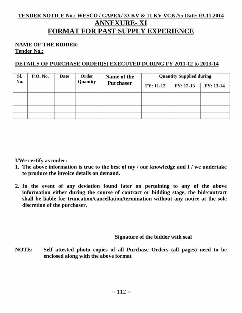
~ 112 ~
TENDER NOTICE No.: WESCO / CAPEX/ 33 KV & 11 KV VCB /55 Date: 03.11.2014 ANNEXURE- XI
FORMAT FOR PAST SUPPLY EXPERIENCE
NAME OF THE BIDDER:
Tender No.:
DETAILS OF PURCHASE ORDER(S) EXECUTED DURING FY 2011-12 to 2013-14
Sl.
No. P.O. No. Date Order
Quantity Name of the
Purchaser
Quantity Supplied during
FY: 11-12 FY: 12-13 FY: 13-14
I/We certify as under:
1. The above information is true to the best of my / our knowledge and I / we undertake
to produce the invoice details on demand.
2. In the event of any deviation found later on pertaining to any of the above
information either during the course of contract or bidding stage, the bid/contract
shall be liable for truncation/cancellation/termination without any notice at the sole
discretion of the purchaser.
Signature of the bidder with seal
NOTE: Self attested photo copies of all Purchase Orders (all pages) need to be
enclosed along with the above format