Werkstoff: Glasfaserverstärktes Vinylesterharz (VE ...
28
2.0 VE-PN16 VE-Klebesystem PN 16 VE-Bonded System PN 16 Date: Release: 30.06.2009 05 Werkstoff: Glasfaserverstärktes Vinylesterharz (VE), Druckstufe: PN16 Material: Glass-fiber reinforced Vinylester Resin, Pressure Classification: PN 16 (16 bar) Artikelübersicht / Product Listing: Artikel/ Article Regis- ter Nennweite/ Diameter Verbindung/ Type of connection Allgemeine Beschreibung Wickelrohr/ 2.0 a General description filament-would Pipe Rohr / Pipe 2.1 a DN 25 – DN 150 zyl./ cylindrical 2.1 b DN 200 – DN 500 kon./ conical Bogen 45° / Elbow 45° 2.2 a DN 25 – DN 150 zyl./ cylindrical 2.2 b DN 200 – DN 500 kon./ conical Bogen 90° / Elbow 90° 2.3 a DN 25 – DN 150 zyl./ cylindrical 2.3 b DN 200 – DN 500 kon./ conical T-Stück / Tee 2.4 a DN 25 – DN 150 zyl./ cylindrical 2.4 b DN 200 – DN 500 kon./ conical Konz. Reduzierung / Conc. Reducer 2.6 a DN 25 – DN 150 zyl./ cylindrical 2.6 b DN 200 – DN 500 kon./ conical Exz. Reduzierung / Ecc. Reducer 2.7 a DN 25 – DN 150 zyl./ cylindrical 2.7 b DN 200 – DN 500 kon./ conical Bund/ Collar, DIN 2501 2.8 a DN 25 – DN 150 zyl./ cylindrical 2.8 b DN 200 – DN 500 kon./ conical Bund/ Collar, ANSI B 16.5 2.8 c DN 25 – DN 150 zyl./ cylindrical 2.8 d DN 200 – DN 500 kon./ conical Losflansche / Loose Flange DIN 2501 2.9 a DN 25 – DN 500 ANSI B 16.5 2.9 b DN 25 – DN 500 Blindflansche / Blind Flange DIN 2501 2.11 a DN 25 – DN 500 ANSI B 16.5 2.11 b DN 25 – DN 500 Muffen / Coupling 2.14 a DN 25 – DN 150 zyl./ cylindrical 2.14 b DN 200 – DN 500 kon./ conical
Transcript of Werkstoff: Glasfaserverstärktes Vinylesterharz (VE ...

2.0
VE-PN16
VE-Klebesystem PN 16
VE-Bonded System PN 16 Date: Release:
30.06.2009 05
Werkstoff: Glasfaserverstärktes Vinylesterharz (VE), Druckstufe: PN16 Material: Glass-fiber reinforced Vinylester Resin, Pressure
Classification: PN 16 (16 bar)
Artikelübersicht / Product Listing:
Artikel/ Article Regis-
ter Nennweite/ Diameter
Verbindung/ Type of connection
Allgemeine Beschreibung Wickelrohr/ 2.0 a General description filament-would Pipe
Rohr / Pipe 2.1 a DN 25 – DN 150 zyl./ cylindrical
2.1 b DN 200 – DN 500 kon./ conical
Bogen 45° / Elbow 45° 2.2 a DN 25 – DN 150 zyl./ cylindrical
2.2 b DN 200 – DN 500 kon./ conical
Bogen 90° / Elbow 90° 2.3 a DN 25 – DN 150 zyl./ cylindrical
2.3 b DN 200 – DN 500 kon./ conical
T-Stück / Tee 2.4 a DN 25 – DN 150 zyl./ cylindrical
2.4 b DN 200 – DN 500 kon./ conical
Konz. Reduzierung / Conc. Reducer 2.6 a DN 25 – DN 150 zyl./ cylindrical
2.6 b DN 200 – DN 500 kon./ conical
Exz. Reduzierung / Ecc. Reducer 2.7 a DN 25 – DN 150 zyl./ cylindrical 2.7 b DN 200 – DN 500 kon./ conical
Bund/ Collar, DIN 2501 2.8 a DN 25 – DN 150 zyl./ cylindrical 2.8 b DN 200 – DN 500 kon./ conical Bund/ Collar, ANSI B 16.5 2.8 c DN 25 – DN 150 zyl./ cylindrical 2.8 d DN 200 – DN 500 kon./ conical
Losflansche / Loose Flange DIN 2501 2.9 a DN 25 – DN 500 ANSI B 16.5 2.9 b DN 25 – DN 500
Blindflansche / Blind Flange DIN 2501 2.11 a DN 25 – DN 500 ANSI B 16.5 2.11 b DN 25 – DN 500
Muffen / Coupling 2.14 a DN 25 – DN 150 zyl./ cylindrical 2.14 b DN 200 – DN 500 kon./ conical
2.0a allg. Beschreibung general description
Wickelrohre und Formstücke
Filament-Wound Pipes and Fittings
Date: Release:
16.09.2009 05
ALLGEMEINE BESCHREIBUNG FKT - WICKELROHRE UND FITTINGS DN 25 – DN 1000
WICKELROHRE FKT - Wickelrohre werden aus Vinylesterharz und Glasfaserrovings im Wickelverfahren (Filament-
Winding-Verfahren) hergestellt. Das automatisch ablaufende maschinelle Fertigungsverfahren mit anschließender Härtung sichert hohe und gleichblei-
bende mechanische Festigkeiten. Für besonders aggressive Medien erhalten die Rohrsysteme eine Chemieschutzschicht von 2,5 mm. FKT Wickelrohre
Typ VE und CSVE (Vinylesterharz) sind als Standardprogramm in den Nennweiten von 25 mm bis 1000 mm für die Druckstufen PN 10 und 16,
sowie auf Anfrage in Nennweiten bis 2000 lieferbar. FKT-Wickelrohre werden standardmäßig mit werk-seitig angewickelter Glockenmuffe und entspre-
chend vorbereitetem Spitzende für eine Verbindung durch kleben oder mit glatten Enden zum verbinden durch Laminatverbindung geliefert. Die Klebever-
bindung ermöglicht bei langem und überwiegend geradem Leitungsverlauf oberirdisch und erdverlegt
eine schnelle Montage.
GENERAL DESCRIPTION OF THE FKT FILAMENT - WOUND PIPES AND FITTINGS DN 25 – DN 1000
FILAMENT - WOUND PIPES Filament-wound FKT pipes are manufactured from vinyl ester resin and glass fiber roving in the filament-winding process. The automated produc-
tion process followed by temperature controlled curing, ensures consistent and high mechanical strength. The piping system can be provided with a
protective chemical barrier of 2.5 mm which provides protection and long service life against especially aggressive media.
FKT filament-wound pipes of type VE (Vinyl Ester) and CSVE (Corrosive Service Vinyl Ester) are
available in the standard product range with nominal diameters of 25-1000 mm for pressures 10 and 16 bar (nominal pressure). Nominal diameters up to
2000 mm are available on request. FKT filament-wound pipes are supplied with integral bell and spigot ends for a bonded connection or with
plain ends for laminated bond. The bell spigot joint allows for fast installation in the case of long and mainly straight runs both for buried and above
ground applications. The laminated joint allows for complex piping configurations and close quarter installation in confined spaces as well as proven
long term reliability.
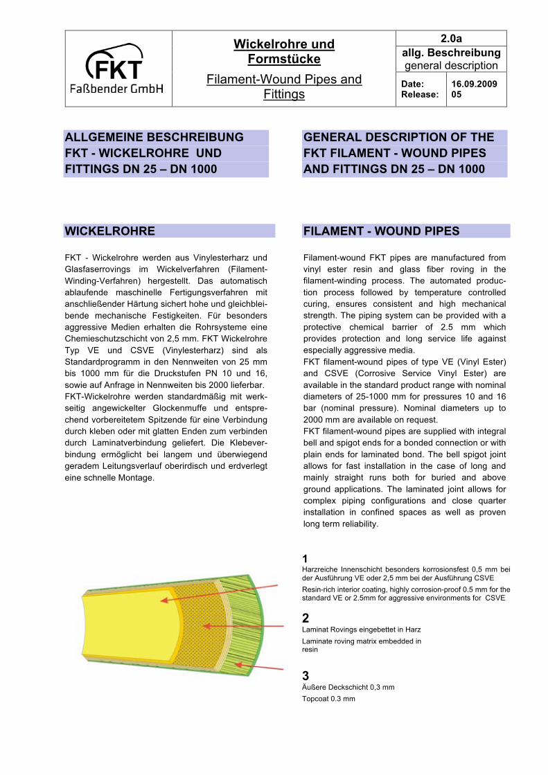
1 Harzreiche Innenschicht besonders korrosionsfest 0,5 mm bei der Ausführung VE oder 2,5 mm bei der Ausführung CSVE
Resin-rich interior coating, highly corrosion-proof 0.5 mm for the standard VE or 2.5mm for aggressive environments for CSVE
2 Laminat Rovings eingebettet in Harz
Laminate roving matrix embedded in resin
3 Äußere Deckschicht 0,3 mm
Topcoat 0.3 mm

2.0a allg. Beschreibung general description
Wickelrohre und Formstücke
Filament-Wound Pipes and Fittings
Date: Release:
16.09.2009 05
FITTINGS
FKT – Formstücke werden aus Vinylesterharz herge-stellt.
Es kommen bei der Herstellung Glasmatten und Gewebe zum Einsatz. Dabei werden die Formstücke
ebenfalls entsprechend dem Rohr mit einer Chemie-schutzschicht von 0,5 mm (Typ VE) oder 2,5 mm (Typ CSVE) geliefert.
Die folgenden Maßtabellen enthalten alle lieferbaren Standardformstücke. Durch die Vielzahl der ver-schiedenen Arten von Formstücken ist die Aus-
führung auch komplizierter Rohrsysteme möglich. Die Formstücke werden im Wickelverfahren, oder im Handauflegeverfahren hergestellt. Neben den in
diesen Tabellen aufgeführten Standardformstücken werden für besondere Rohrverläufe auch Sonder-formstücke erstellt.
WERKSTOFF GFK ist ein Verbundwerkstoff, der sich aus zwei
unterschiedlichen Komponenten zusammensetzt. Verstärkungsfasern aus Textilglas zeichnen sich durch ihre hohe mechanische Belastbarkeit aus,
duroplastische Harzsysteme sind bekannt für ihre ausgezeichnete Chemikalienbeständigkeit. Kombi-niert man die beiden Komponenten, erhält man ein
Produkt, das die Vorteile beider vereinigt. Die charakteristischen Eigenschaften dieses Ver-bundwerkstoffes lassen sich durch den Volumen-
gehalt und Orientierung der Glasfasern ebenso wie durch die Wahl des Harztypes individuell einstellen. Als Matrixwerkstoff verwendet FKT Vinylester-
harzsysteme. Diese sind vor und während der Verarbeitung flüssig. Die Glasfasern werden mit dem Harz getränkt und bei Rohren im Kreuzwickel-
Verfahren in die gewünschte Form gebracht. Nach der Formgebung härtet der Verbundwerkstoff unter
Zugabe von Wärme durch chemische Reaktion aus. Wegen seiner duroplastischen Eigenschaften ist der Verbundwerkstoff GFK auch bei hohen Temperaturen
nicht mehr verformbar und zeichnet sich durch hohe mechanische Belastbarkeit aus. Berücksichtigt man zudem die optimale Korrosions-
und Chemikalienbeständigkeit bei gleichzeitig geringem Gewicht, eröffnen sich GFK-Rohrsystemen vielseitige Einsatzgebiete bei langzeitiger Betriebs-
sicherheit. Die Korrosionsfestigkeit ist einer separa-ten Korrosionstabelle zu entnehmen.
FITTINGS
The standard fittings from FKT are made of vinyl ester resin. At the production there is glass woven roving and veil applied. The fittings are
manufactured and supplied in accordance with the Pipe Specification, with a protective chemical barrier of 0.5 mm (type VE) or 2.5 mm (type CSVE).
The dimension table, includes all available standard fittings. The wide range of standard and custom
fittings enables the realization of complex piping systems. FKT fittings are manufactured utilizing the filament-winding or hand lay-up processes. In
addition to the standard fittings contained in these tables, special fittings are available for special pipeline configurations.
MATERIAL Glass Fiber Reinforced plastic is a composite material, comprising two different components.
Reinforcing fibers made of textile glass that possess excellent mechanical strength, while duroplastic resins are known for their excellent resistance to
chemical attack. The combination of these two components results in a single product that provides the advantages of both.
The characteristic properties of this composite material can be individually fine-tuned by modification of the proportion by volume and
orientation of the glass fibers and selection of the type of resin. FKT uses both Epoxy and Vinyl Ester resins as the
resin matrix material. These remain liquid before and during the production process. The glass fibers are impregnated with resin and are applied under
tension into the desired shape in the filament-winding process. After forming the desired shape, the composite material is cured under controlled
temperature. Because of its duroplastic properties, glass fiber reinforced plastic retains its shape and high
mechanical strength even at elevated temperatures. These properties, together with optimum resistance
to corrosion, chemical attack and light weight, allow glass fiber reinforced plastic piping systems to be used in many applications where long-term
operational safety is a must.(see corrosion brochure)

2.0a allg. Beschreibung general description
Wickelrohre und Formstücke
Filament-Wound Pipes and Fittings
Date: Release:
16.09.2009 05
Die werkstoffgerechte Fertigung, unter Berück-sichtigung der branchenspezifischen DIN und EN -Normen, unterliegt einem strengen Qualitätssicher-
ungssystem. Aufgrund kontinuierlicher amtlicher Qualitätsüberwachungen haben FKT-Rohrsysteme Zu-
lassungen für zahlreiche Anwendungsbereiche.
VERBINDUNGSTECHNIKEN
Ein wesentlicher Faktor bei der Bewertung von
Kunststoff-Rohrsystemen stellt die Verbindungs-technik der Rohre und Formstücke miteinander dar. FKT-Rohrsysteme bieten dafür einen weiten Bereich
an bewährten, werkstoffgerechten Möglichkeiten.
KLEBEVERBINDUNG
Die Klebetechnik ist die häufigste eingesetzte Verbindungsmethode für GFK-Rohrleitungssysteme. Besonders bewährt hat sich die Klebetechnik für
Anwendungen in der chemischen Industrie. FKT wendet standardmäßig die Klebetechnik bis zur
Nennweite DN 500 unter Verwendung spezieller, auf das jeweilige Rohrsystem und den Anwendungsfall abgestimmter Mehrkomponenten-Kleber an.
Vorbereitung und Handhabung erfolgen nach der „Verarbeitungsanleitung für FKT-Rohrsysteme“.
LAMINIERVERBINDUNG
Bei Nennweiten > 500 und besonderen Anfor-derungen können die Verbindungen durch Laminier-
verbindung erfolgen. Glatte Rohrenden und Formteile werden durch die Laminierverbindung in der Vorkon-fektion und auf der Baustelle langzeitig sicher
zusammengefügt.
FLANSCHVERBINDUNG
Bei komplizierten Isometrien mit häufigen Demon-tageerfordernissen werden lösbare Flanschver-bindungen mit Anschlußmaßen nach DIN oder ANSI
verwendet. Ein Sortiment von Fest- und Los-flanschen aus GFK und Metall stehen hierbei zur Verfügung.
Our material-oriented production is subject to strict quality control systems, according to the relevant DIN and EN standards in force. Continuous monitoring of
quality and compliance with official standards has resulted in FKT piping systems being approved for many areas of application.
CONNECTING TECHNIQUES An essential benchmark in evaluating plastic piping systems is the technology applied in connecting pipes
and fittings. Here, FKT provides a wide-range of tried-and-tested material-based options
BONDED CONNECTION
Bonding is the most frequently used technique for connecting glass fiber reinforced pipeline systems.
Bonding has proved especially effective in chemical industry applications. At FKT, the bonding technique is standard for nominal diameters up to 500 mm. The
adhesive system used depends on the piping system and application. Preparation and handling are described in “Handling
Instructions for FKT Pipe Systems”.
LAMINATED CONNECTION
For diameters > 500 and in the case of special
requirements, connections can be made by laminated process. Laminated joints provide safe and lasting connections for plain end pipe and fittings for both
prefabricated subassemblies and assembly on site.
FLANGE CONNECTION
In the case of complicated isometrics which may
have to be frequently disassembled, connections are carried out using flanges with bolt patterns in accordance with DIN or ANSI standards.
2.0a allg. Beschreibung general description
Wickelrohre und Formstücke
Filament-Wound Pipes and Fittings
Date: Release:
16.09.2009 05
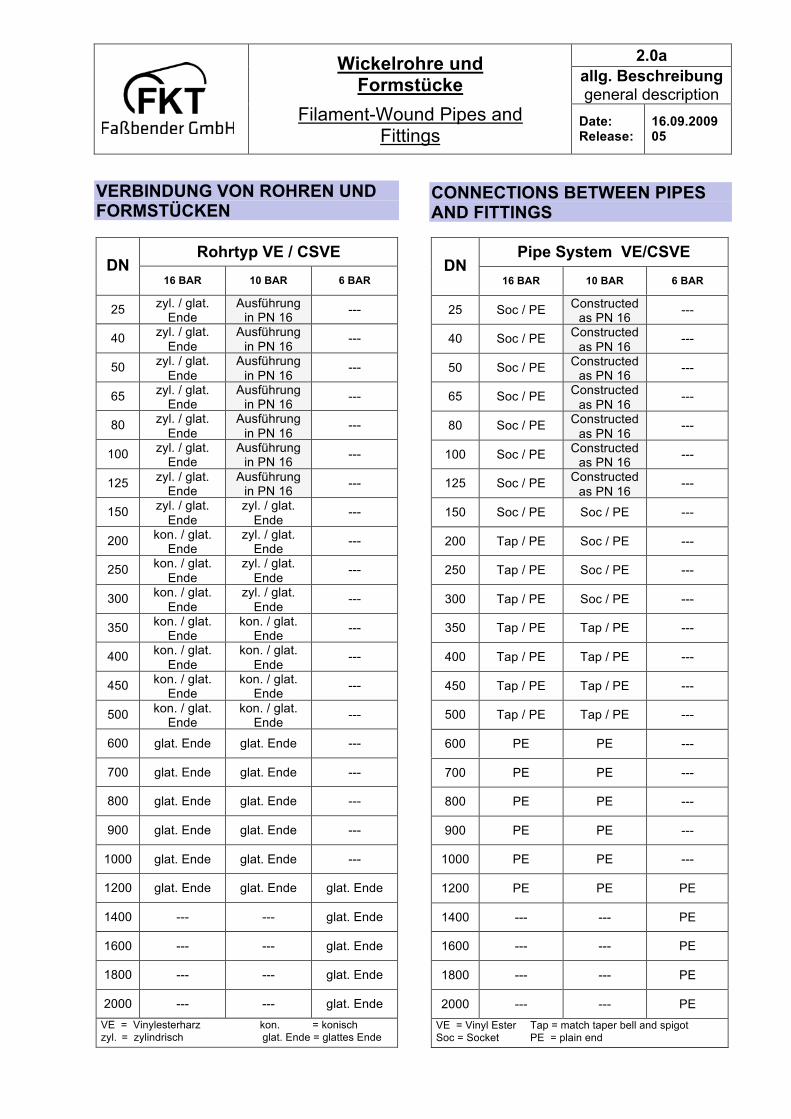
VERBINDUNG VON ROHREN UND FORMSTÜCKEN
Rohrtyp VE / CSVE DN
16 BAR 10 BAR 6 BAR
25 zyl. / glat. Ende
Ausführung in PN 16
---
40 zyl. / glat. Ende
Ausführung in PN 16
---
50 zyl. / glat. Ende
Ausführung in PN 16
---
65 zyl. / glat. Ende
Ausführung in PN 16
---
80 zyl. / glat. Ende
Ausführung in PN 16
---
100 zyl. / glat. Ende
Ausführung in PN 16
---
125 zyl. / glat. Ende
Ausführung in PN 16
---
150 zyl. / glat. Ende
zyl. / glat. Ende
---
200 kon. / glat. Ende
zyl. / glat. Ende
---
250 kon. / glat. Ende
zyl. / glat. Ende
---
300 kon. / glat. Ende
zyl. / glat. Ende
---
350 kon. / glat. Ende
kon. / glat. Ende
---
400 kon. / glat. Ende
kon. / glat. Ende
---
450 kon. / glat. Ende
kon. / glat. Ende
---
500 kon. / glat. Ende
kon. / glat. Ende
---
600 glat. Ende glat. Ende ---
700 glat. Ende glat. Ende ---
800 glat. Ende glat. Ende ---
900 glat. Ende glat. Ende ---
1000 glat. Ende glat. Ende ---
1200 glat. Ende glat. Ende glat. Ende
1400 --- --- glat. Ende
1600 --- --- glat. Ende
1800 --- --- glat. Ende
2000 --- --- glat. Ende
VE = Vinylesterharz kon. = konisch zyl. = zylindrisch glat. Ende = glattes Ende
CONNECTIONS BETWEEN PIPES AND FITTINGS
Pipe System VE/CSVE DN
16 BAR 10 BAR 6 BAR
25 Soc / PE Constructed as PN 16
---
40 Soc / PE Constructed as PN 16 ---
50 Soc / PE Constructed as PN 16 ---
65 Soc / PE Constructed as PN 16 ---
80 Soc / PE Constructed as PN 16 ---
100 Soc / PE Constructed as PN 16 ---
125 Soc / PE Constructed as PN 16 ---
150 Soc / PE Soc / PE ---
200 Tap / PE Soc / PE ---
250 Tap / PE Soc / PE ---
300 Tap / PE Soc / PE ---
350 Tap / PE Tap / PE ---
400 Tap / PE Tap / PE ---
450 Tap / PE Tap / PE ---
500 Tap / PE Tap / PE ---
600 PE PE ---
700 PE PE ---
800 PE PE ---
900 PE PE ---
1000 PE PE ---
1200 PE PE PE
1400 --- --- PE
1600 --- --- PE
1800 --- --- PE
2000 --- --- PE VE = Vinyl Ester Tap = match taper bell and spigot Soc = Socket PE = plain end

2.0a allg. Beschreibung general description
Wickelrohre und Formstücke
Filament-Wound Pipes and Fittings
Date: Release:
16.09.2009 05
QUALITÄTSSICHERUNG FKT ist der weltweit geschützte Handelsname unserer bewährten Erzeugnisse aus glasfaser-verstärktem Kunststoff. Er steht für Sicherheit und
Fortschritt. Eine breite Produktpalette von Rohrsystemen aus
GFK in Verbindung mit einem soliden Engineering und einer eigenen Montage unterstreicht unsere Leistungen für die Bewältigung immer höherer
technischer Erfordernisse in Gegenwart und Zukunft. Erzeugnisse der FKT bieten Vorteile durch jahrelange
Erfahrungen mit GFK, durch werkstoffgerechte Ver-arbeitungsmethoden und ein umfangreiches Qua-litätssicherungssystem nach DIN EN ISO 9001.
Systematisch durchgeführte Prüfungen und Tests sichern die gleichbleibende hohe Qualität aller FKT-
Erzeugnisse. Der Verwendung von Standard-Test-methoden kommt eine große Bedeutung zu bei der Konstruktion, Qualitätskontrolle und der Erstellung
von technischen Spezifikationsdaten für unsere FKT-Rohrsysteme. Hierdurch werden wichtige Eigen-schaften des Werkstoffes regelmäßig überprüft. Es
wird verhindert, daß Produkte zum Einsatz gelangen, die nicht den in FKT-Katalogen aufgeführten An-gaben entsprechen.
Die FKT-Qualitätskontrolle bringt Ihnen Sicherheit bei der Verwendung von FKT-Materialien und Produkten.
Nach den FKT-Standard-Testmethoden werden die zur Produktion erforderlichen Rohstoffe und die End-produkte geprüft. Diese Testmethoden werden so-
wohl auf das Rohmaterial über den Herstellungs-prozess als auch auf das fertige Produkt angewandt.
Die Standard-Testmethoden entsprechen den inter-nationalen Anforderungen, d.h. den DIN-, EN- oder ASTM-Prüfnormen. Die FKT verwendet weiterhin
Werknormen, die an diese Prüfnormen angelehnt sind. Diese Prüfungen gewährleisten einen gleich-
bleibend hohen Qualitätsstandard der FKT-Produkte.
QUALITY CONTROL FKT is the world-copyright commercial name of the quality glass fiber reinforced products which we have produced and supplied. The FKT Company stands
for and promotes safety and the technical advancement of engineering, composites and manufacturing.
A wide range of piping system products made of glass fiber reinforced plastic backed by solid
engineering know-how and in house assembly ensures our ability to cope successfully with the
technically and evermore challenging tasks of both today and tomorrow. The advantages provided by FKT products are attributable to years of experience
with glass fiber reinforced plastics, manufacturing techniques adapted to raw materials, and a comprehensive quality control system to DIN EN ISO
9001. Systematically carried-out checks and tests ensure
the continually high quality standard of FKT products. The application of standard test procedures is of central importance in the design, quality control and
technical data gathering for our FKT pipe systems. In this way, the key properties of the raw materials are systematically controlled. This ensures that no
product can be supplied unless it meets the specification details outlined in the FKT catalogue.
FKT’s quality control means that customers can have full confidence when using our products. The raw materials used in our production, as well as the final
products, undergo comprehensive testing to FKT’s standard test procedures. These test procedures are applied to raw materials in the manufacturing
process, and also to our finished products. The standard test procedures are in compliance with
international testing requirements, i. e. German DIN, EN or ASTM test standards. In addition, FKT applies
factory developed and client specified test procedures. These tests ensure the consistently high quality standard of FKT products.
2.1a
VE-PN16
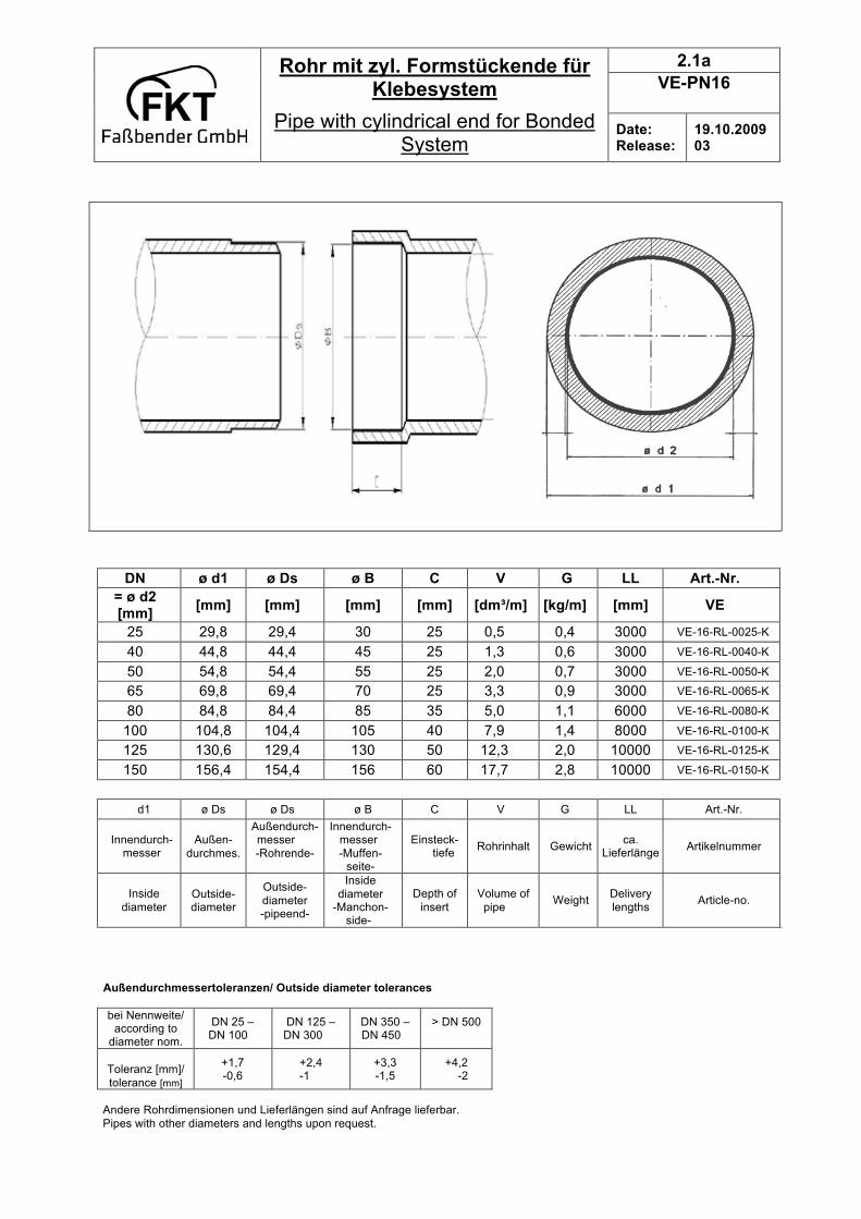
Rohr mit zyl. Formstückende für Klebesystem
Pipe with cylindrical end for Bonded System
Date: Release:
19.10.2009 03
DN ø d1 ø Ds ø B C V G LL Art.-Nr.
= ø d2 [mm]
[mm] [mm] [mm] [mm] [dm³/m] [kg/m] [mm] VE
25 29,8 29,4 30 25 0,5 0,4 3000 VE-16-RL-0025-K
40 44,8 44,4 45 25 1,3 0,6 3000 VE-16-RL-0040-K
50 54,8 54,4 55 25 2,0 0,7 3000 VE-16-RL-0050-K
65 69,8 69,4 70 25 3,3 0,9 3000 VE-16-RL-0065-K
80 84,8 84,4 85 35 5,0 1,1 6000 VE-16-RL-0080-K
100 104,8 104,4 105 40 7,9 1,4 8000 VE-16-RL-0100-K
125 130,6 129,4 130 50 12,3 2,0 10000 VE-16-RL-0125-K
150 156,4 154,4 156 60 17,7 2,8 10000 VE-16-RL-0150-K
d1 ø Ds ø Ds ø B C V G LL Art.-Nr.
Innendurch-messer
Außen-
durchmes.
Außendurch-messer
-Rohrende-
Innendurch-messer
-Muffen- seite-
Einsteck- tiefe
Rohrinhalt Gewicht ca.
Lieferlänge Artikelnummer
Inside
diameter
Outside- diameter
Outside-
diameter -pipeend-
Inside
diameter -Manchon-
side-
Depth of
insert
Volume of
pipe Weight
Delivery
lengths Article-no.
A Außendurchmessertoleranzen/ Outside diameter tolerances
bei Nennweite/ according to
diameter nom.
DN 25 – DN 100
DN 125 – DN 300
DN 350 – DN 450
> DN 500
Toleranz [mm]/
tolerance [mm]
+1,7 -0,6
+2,4 -1
+3,3 -1,5
+4,2 -2
Andere Rohrdimensionen und Lieferlängen sind auf Anfrage lieferbar.
Pipes with other diameters and lengths upon request.
2.1b
VE-PN16
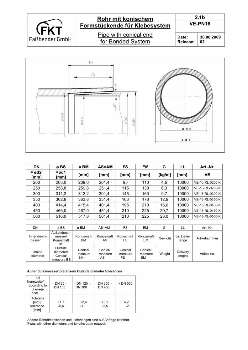
Rohr mit konischem Formstückende für Klebesystem
Pipe with conical end for Bonded System
Date: Release:
30.06.2009 02
DN ø BS ø BM AS=AM FS EM G LL Art.-Nr.
= ød2 [mm]
=ød1 [mm]
[mm] [mm] [mm] [mm] [kg/m] [mm] VE
200 208,0 209,0 201,4 95 110 4,6 10000 VE-16-RL-0200-K
250 258,8 259,8 251,4 115 130 6,3 10000 VE-16-RL-0250-K
300 311,2 312,2 301,4 145 160 9,7 10000 VE-16-RL-0300-K
350 362,8 363,8 351,4 163 178 12,9 10000 VE-16-RL-0350-K
400 414,4 415,4 401,4 195 210 16,6 10000 VE-16-RL-0400-K
450 466,0 467,0 451,4 210 225 20,7 10000 VE-16-RL-0450-K
500 516,0 517,0 501,4 210 225 23,0 10000 VE-16-RL-0500-K
DN ø BS ø BM AS=AM FS EM G LL Art.-Nr.
Innendurch-messer
Außendurch-messer/
Konusmaß BS
Konusmaß BM
Konusmaß AS
Konusmaß FS
Konusmaß EM
Gewicht ca. Liefer-
länge Artikelnummer
Inside
diameter
Outside
diameter/ Conical
measure BS
Conical
measure BM
Conical
measure AS
Conical
measure FS
Conical
measure EM
Weight Delivery
lengths Article-no.
Außendurchmessertoleranzen/ Outside diameter tolerances
bei Nennweite/ according to
diameter nom.
DN 25 – DN 100
DN 125 – DN 300
DN 350 – DN 450
> DN 500
Toleranz
[mm]/ tolerance
[mm]
+1,7
-0,6
+2,4
-1
+3,3
-1,5
+4,2
-2
Andere Rohrdimensionen und- lieferlängen sind auf Anfrage lieferbar. Pipes with other diameters and lengths upon request.
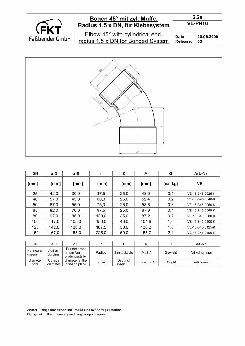
2.2a
VE-PN16
Bogen 45° mit zyl. Muffe, Radius 1,5 x DN, für Klebesystem
Elbow 45° with cylindrical end, radius 1,5 x DN for Bonded System
Date: Release:
30.06.2009 03
DN ø D ø B r C A G Art.-Nr.
[mm]
[mm] [mm] [mm] [mm] [mm] [ca. kg] VE
25 42,0 30,0 37,5 25,0 43,0 0,1 VE-16-B45-0025-K
40 57,0 45,0 60,0 25,0 52,4 0,2 VE-16-B45-0040-K
50 67,0 55,0 75,0 25,0 58,6 0,3 VE-16-B45-0050-K
65 82,0 70,0 97,5 25,0 67,9 0,4 VE-16-B45-0065-K
80 97,0 85,0 120,0 35,0 87,2 0,7 VE-16-B45-0080-K
100 117,0 105,0 150,0 40,0 104,6 1,0 VE-16-B45-0100-K
125 142,0 130,0 187,5 50,0 130,2 1,8 VE-16-B45-0125-K
150 167,0 155,0 225,0 60,0 155,7 2,1 VE-16-B45-0150-K
DN ø D ø B r C A G Art.-Nr.
Nenndurch
-messer
Außen-
durchm.
Durchmesser
an der Ver- bindungsstelle
Radius Einstecktiefe Maß A Gewicht Artikelnummer
diameter nom.
Outside diameter
diameter at the bonding place
radius Depth of insert
measure A Weight Article-no.
Andere Fittingdimensionen und -maße sind auf Anfrage lieferbar.
Fittings with other diameters and lengths upon request.

2.2b
VE-PN16
Bogen 45° mit konischer Muffe, Radius 1,5 x DN, für Klebesystem
Elbow 45° with conical end, radius 1,5 x DN, for Bonded System
Date: Release:
30.06.2009 03
DN ø D ø B1 ø B2 r C A G Art.-Nr.
[mm]
[mm] [mm] [mm] [mm] [mm] [mm] [ca. kg] VE
200 223 209,0 201,4 300 110 236,8 3,8 VE-16-B45-0200-K
250 275 259,8 251,4 375 130 287,8 5,9 VE-16-B45-0250-K
300 331 312,2 301,4 450 160 348,9 11,0 VE-16-B45-0300-K
350 385 363,8 351,4 525 178 400,5 16,8 VE-16-B45-0350-K
400 439 415,4 401,4 600 210 461,0 24,4 VE-16-B45-0400-K
450 493 467,0 451,4 675 225 509,6 33,9 VE-16-B45-0450-K
500 543 517,0 501,4 750 225 540,7 39,7 VE-16-B45-0500-K
DN ø D ø B1 ø B2 r C A G Art.-Nr.
Nenndurch
-messer
Außen-
durchm.
Durchmesser 1
an der Ver- bindungsstelle
Durchmesser 2
an der Ver- bindungsstelle
Radius Einsteck-
tiefe Maß A Gewicht Artikelnummer
diameter
nom.
Outside
diameter
diameter 1 at
bonding place
diameter 2 at
bonding place radius
Depth of
insert measure A Weight Article-no.
Andere Fittingdimensionen und -maße sind auf Anfrage lieferbar.
Fittings with other diameters and lengths upon request.

2.3a
VE-PN16
Bogen 90° mit zyl. Muffe, Radius 1,5 x DN für Klebesystem
Elbow 90° with cylindrical end, radius 1,5 x DN for Bonded System
Date: Release:
30.06.2009 02
DN ø D ø B r C A G Art.-Nr.
[mm]
[mm] [mm] [mm] [mm] [mm] [ca. kg] VE
25 42,0 30,0 37,5 25 65,0 0,1 VE-16-B90-0025-K
40 57,0 45,0 60,0 25 87,5 0,2 VE-16-B90-0040-K
50 67,0 55,0 75,0 25 102,5 0,3 VE-16-B90-0050-K
65 82,0 70,0 97,5 25 125,0 0,4 VE-16-B90-0065-K
80 97,0 85,0 120,0 35 157,5 0,7 VE-16-B90-0080-K
100 117,0 105,0 150,0 40 192,5 1,0 VE-16-B90-0100-K
125 142,0 130,0 187,5 50 240,0 1,8 VE-16-B90-0125-K
150 167,0 156,0 225,0 60 287,5 2,3 VE-16-B90-0150-K
DN ø D ø B r C A G Art.-Nr.
Nenndurch-messer
Außen- durchm.
Durchmesser an der Ver-
bindungsstelle
Radius Einstecktiefe Maß A Gewicht Artikelnummer
diameter nom.
Outside diameter
diameter at the bonding place
radius Depth of insert
measure A Weight Article-no.
Andere Fittingdimensionen und -maße sind auf Anfrage lieferbar.
Fittings with other diameters and lengths upon request.
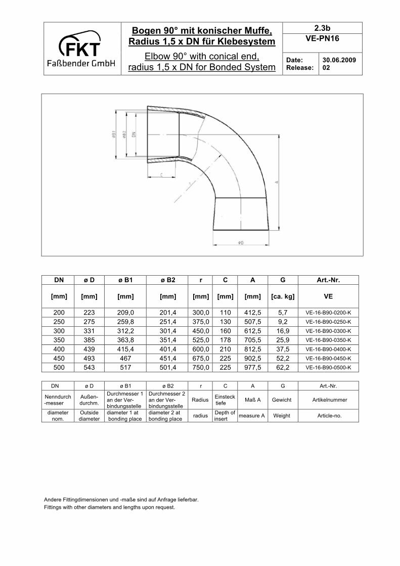
2.3b
VE-PN16
Bogen 90° mit konischer Muffe, Radius 1,5 x DN für Klebesystem
Elbow 90° with conical end, radius 1,5 x DN for Bonded System
Date: Release:
30.06.2009 02
DN ø D ø B1 ø B2 r C A G Art.-Nr.
[mm]
[mm] [mm] [mm] [mm] [mm] [mm] [ca. kg] VE
200 223 209,0 201,4 300,0 110 412,5 5,7 VE-16-B90-0200-K
250 275 259,8 251,4 375,0 130 507,5 9,2 VE-16-B90-0250-K
300 331 312,2 301,4 450,0 160 612,5 16,9 VE-16-B90-0300-K
350 385 363,8 351,4 525,0 178 705,5 25,9 VE-16-B90-0350-K
400 439 415,4 401,4 600,0 210 812,5 37,5 VE-16-B90-0400-K
450 493 467 451,4 675,0 225 902,5 52,2 VE-16-B90-0450-K
500 543 517 501,4 750,0 225 977,5 62,2 VE-16-B90-0500-K
DN ø D ø B1 ø B2 r C A G Art.-Nr.
Nenndurch
-messer
Außen-
durchm.
Durchmesser 1
an der Ver- bindungsstelle
Durchmesser 2
an der Ver- bindungsstelle
Radius Einsteck
tiefe Maß A Gewicht Artikelnummer
diameter
nom.
Outside
diameter
diameter 1 at
bonding place
diameter 2 at
bonding place radius
Depth of
insert measure A Weight Article-no.
Andere Fittingdimensionen und -maße sind auf Anfrage lieferbar.
Fittings with other diameters and lengths upon request.

2.4a
VE-PN16
T-Stück mit zyl. Formstückende für Klebesystem
Tee with cylindrical end for Bonded System
Date: Release:
30.06.2009 02
DN ø D ø B C A E G Art.-Nr.
= ød1 [mm]
[mm] [mm] [mm] [mm] [mm] [ca. kg] VE
25 42,0 30,0 25 65 130 0,2 VE-16-T-0025-K
40 57,0 45,0 25 75 150 0,4 VE-16-T-0040-K
50 67,0 55,0 25 85 170 0,5 VE-16-T-0050-K
65 82,0 70,0 25 95 190 0,7 VE-16-T-0065-K
80 97,0 85,0 35 115 230 1,1 VE-16-T-0080-K
100 117,0 105,0 40 135 270 1,6 VE-16-T-0100-K
125 142,0 130,0 50 160 320 2,7 VE-16-T-0125-K
150 167,0 155,0 60 190 380 4,3 VE-16-T-0150-K
d1 ø D ø B C A E G Art.-Nr.
Innendurch-messer
Außendurch-
messer
Innendurch-messer
Einsteck- tiefe
Maß Muffenanfang
bis Fitting- mitte
Maß E Gewicht Artikelnummer
Inside
diameter
Outside-
diameter
Inside
diameter
Depth of
insert
measure
manchon to center of
fitting
measure E weight Article-no.
Andere Fittingdimensionen und -längen sind auf Anfrage lieferbar. Fittings with other diameters and lengths upon request.

2.4b
VE-PN16
T-Stück mit konischem Form-stückende für Klebesystem
Tee with conical end for Bonded System
Date: Release:
30.06.2009 02
DN ø D ø B1 ø B2 C A E G Art.-Nr.
= ød1 [mm]
[mm] [mm] [mm] [mm] [mm] [mm] [ca. kg] VE
200 223 209,0 201,4 110 287 574 7,4 VE-16-T-0200-K
250 275 259,8 251,4 130 349 698 11,7 VE-16-T-0250-K
300 331 312,2 301,4 160 420 840 21,3 VE-16-T-0300-K
350 385 363,8 351,4 178 448 896 30,2 VE-16-T-0350-K
400 439 415,4 401,4 210 520 1040 43,7 VE-16-T-0400-K
450 493 467 451,4 225 570 1140 60,3 VE-16-T-0450-K
500 543 517 501,4 225 605 1210 70,7 VE-16-T-0500-K
d1 ø D ø B1 ø B2 C A E G Art.-Nr.
Innendurch-messer
Außendurch
-messer
Innendurch-messer 1
Innendurch-messer 12
Einsteck- tiefe
Maß Muffenanfang
bis Fitting- mitte
Maß E Gewicht Artikelnummer
Inside
diameter
Outside-
diameter
Inside
diameter 1
Inside
diameter 2
Depth of
insert
measure
manchon to center of
fitting
measure E weight Article-no.
Andere Fittingdimensionen und -längen sind auf Anfrage lieferbar.
Fittings with other diameters and lengths upon request.
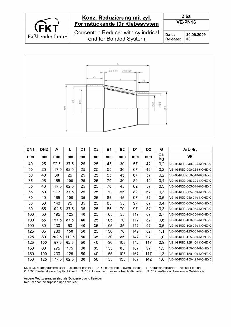
2.6a
VE-PN16
Konz. Reduzierung mit zyl. Formstückende für Klebesystem
Concentric Reducer with cylindrical end for Bonded System
Date: Release:
30.06.2009 03
DN1/ DN2: Nenndurchmesser – Diameter nominal A: Gesamtlänge – overall length L: Reduzierungslänge – Reducer length C1/ C2: Einstecktiefe – Depth of insert B1/ B2: Innendurchmesser – Inside diameter D1/ D2: Außendurchmesser – Outside dia.
Andere Reduzierungen sind als Sonderfertigung lieferbar. Reducer can be supplied upon request.
DN1 DN2 A L C1 C2 B1 B2 D1 D2 G Art.-Nr.
mm mm mm mm mm mm mm mm mm mm Ca. kg
VE
40 25 92,5 37,5 25 25 45 30 57 42 0,2 VE-16-RED-040-025-KONZ-K
50 25 117,5 62,5 25 25 55 30 67 42 0,2 VE-16-RED-050-025-KONZ-K
50 40 80 25 25 25 55 45 67 57 0,2 VE-16-RED-050-040-KONZ-K
65 25 155 100 25 25 70 30 82 42 0,4 VE-16-RED-065-025-KONZ-K
65 40 117,5 62,5 25 25 70 45 82 57 0,3 VE-16-RED-065-040-KONZ-K
65 50 92,5 37,5 25 25 70 55 82 67 0,3 VE-16-RED-065-050-KONZ-K
80 40 165 100 35 25 85 45 97 57 0,5 VE-16-RED-080-040-KONZ-K
80 50 140 75 35 25 85 55 97 67 0,4 VE-16-RED-080-050-KONZ-K
80 65 102,5 37,5 35 25 85 70 97 82 0,3 VE-16-RED-080-065-KONZ-K
100 50 195 125 40 25 105 55 117 67 0,7 VE-16-RED-100-050-KONZ-K
100 65 157,5 87,5 40 25 105 70 117 82 0,6 VE-16-RED-100-065-KONZ-K
100 80 130 50 40 35 105 85 117 97 0,5 VE-16-RED-100-080-KONZ-K
125 65 230 150 50 25 130 70 142 82 1,1 VE-16-RED-125-065-KONZ-K
125 80 202,5 112,5 50 35 130 85 142 97 1,0 VE-16-RED-125-080-KONZ-K
125 100 157,5 62,5 50 40 130 105 142 117 0,8 VE-16-RED-125-100-KONZ-K
150 80 275 175 60 35 155 85 167 97 1,5 VE-16-RED-150-080-KONZ-K
150 100 230 125 60 40 155 105 167 117 1,3 VE-16-RED-150-100-KONZ-K
150 125 177,5 62,5 60 50 155 130 167 142 1,0 VE-16-RED-150-125-KONZ-K

2.6b
VE-PN16
Konz. Reduzierung mit konischem Formstückende für Klebesystem
Concentric Reducer with conical end for Bonded System
Date: Release:
30.06.2009 03
DN1 DN2 A L C1 C2 B11 B12 B21 B22 D1 D2 G Art.-Nr.
mm mm mm mm mm mm mm mm mm mm mm mm Ca. kg
VE
200 100 405 250 110 40 209 201,4 106 105 223 117 3,4 VE-16-RED-200-
100-KONZ-K
200 125 352,5 187,5 110 50 209 201,4 131 130 223 142 3,1 VE-16-RED-200-
125-KONZ-K
200 150 300 125 110 60 209 201,4 157 156 223 167 2,7 VE-16-RED-200-
150-KONZ-K
250 125 497,5 312,5 130 50 259,8 251,4 131 130 271 142 6,4 VE-16-RED-250-
125-KONZ-K
250 150 445 250 130 60 259,8 251,4 157 156 271 167 6,0 VE-16-RED-250-
150-KONZ-K
250 200 370 125 130 110 259,8 251,4 209 201,4 275 223 5,2 VE-16-RED-250-
200-KONZ-K
300 150 600 375 160 60 312,2 301,4 157 156 331 167 11,1 VE-16-RED-300-
150-KONZ-K
300 200 525 250 160 110 312,2 301,4 209 201,4 331 223 10,5 VE-16-RED-300-
200-KONZ-K
300 250 420 125 160 130 312,2 301,4 259,8 251,4 331 275 8,4 VE-16-RED-300-
250-KONZ-K
400 350 518 125 210 178 415,4 401,4 363,8 351,4 427 385 13,7 VE-16-RED-400-
350-KONZ-K
400 300 625 250 210 160 415,4 401,4 312,2 301,4 439 331 12,6 VE-16-RED-400-
300-KONZ-K
400 250 720 375 210 130 415,4 401,4 259,8 251,4 439 275 11,3 VE-16-RED-400-
250-KONZ-K
450 300 765 375 225 160 467 451,4 312,2 301,4 493 331 VE-16-RED-450-
300-KONZ-K
500 350 783 375 225 178 517 501,4 363,8 351,4 543 385 27,2 VE-16-RED-500-
350-KONZ-K
500 400 690 250 225 210 517 501,4 415,4 401,4 543 439 25,1 VE-16-RED-500-
400-KONZ-K
500 450 580 125 225 225 517 501,4 467 451,4 543 493 23,0 VE-16-RED-500-
450-KONZ-K
DN1/ DN2: Nenndurchmesser – Diameter nominal A: Gesamtlänge – overall length L: Reduzierungslänge – Reducer length C1/ C2: Einstecktiefe – Depth of insert B1/ B2: Innendurchmesser – Inside diameter D1/ D2: Außendurchmesser – Outside dia.
Andere Reduzierungen sind als Sonderfertigung lieferbar. Reducer can be supplied upon request.

2.7a
VE-PN16
Exz. Reduzierung mit zyl. Formstückende für Klebesystem
Eccentric Reducer with cylindrical end for Bonded System
Date: Release:
30.06.2009 03
DN1/ DN2: Nenndurchmesser – Diameter nominal A: Gesamtlänge – overall length L: Reduzierungslänge – Reducer length
C1/ C2: Einstecktiefe – Depth of insert B1/ B2: Innendurchmesser – Inside diameter D1/ D2: Außendurchmesser – Outside dia. Andere Reduzierungen sind als Sonderfertigung lieferbar.
Reducer can be supplied upon request.
DN1 DN2 A L C1 C2 B1 B2 D1 D2 G Art.-Nr.
mm mm mm mm mm mm mm mm mm mm Ca. kg
VE
40 25 92,5 37,5 25 25 45 30 57 42 0,2 VE-16-RED-040-025-
EXZ-K
50 25 117,5 62,5 25 25 55 30 67 42 0,2 VE-16-RED-050-025-
EXZ-K
50 40 80 25 25 25 55 45 67 57 0,2 VE-16-RED-050-040-
EXZ-K
65 25 155 100 25 25 70 30 82 42 0,4 VE-16-RED-065-025-
EXZ-K
65 40 117,5 62,5 25 25 70 45 82 57 0,3 VE-16-RED-065-040-
EXZ-K
65 50 92,5 37,5 25 25 70 55 82 67 0,3 VE-16-RED-065-050-
EXZ-K
80 40 165 100 35 25 85 45 97 57 0,5 VE-16-RED-080-040-
EXZ-K
80 50 140 75 35 25 85 55 97 67 0,4 VE-16-RED-080-050-
EXZ-K
80 65 102,5 37,5 35 25 85 70 97 82 0,3 VE-16-RED-080-065-
EXZ-K
100 50 195 125 40 25 105 55 117 67 0,7 VE-16-RED-100-050-
EXZ-K
100 65 157,5 87,5 40 25 105 70 117 82 0,6 VE-16-RED-100-065-
EXZ-K
100 80 130 50 40 35 105 85 117 97 0,5 VE-16-RED-100-080-
EXZ-K
125 65 230 150 50 25 130 70 142 82 1,1 VE-16-RED-125-065-
EXZ-K
125 80 202,5 112,5 50 35 130 85 142 97 1,0 VE-16-RED-125-080-
EXZ-K
125 100 157,5 62,5 50 40 130 105 142 117 0,8 VE-16-RED-125-100-
EXZ-K
150 80 275 175 60 35 155 85 167 97 1,5 VE-16-RED-150-080-
EXZ-K
150 100 230 125 60 40 155 105 167 117 1,3 VE-16-RED-150-100-
EXZ-K
150 125 177,5 62,5 60 50 155 130 167 142 1,0 VE-16-RED-150-125-
EXZ-K
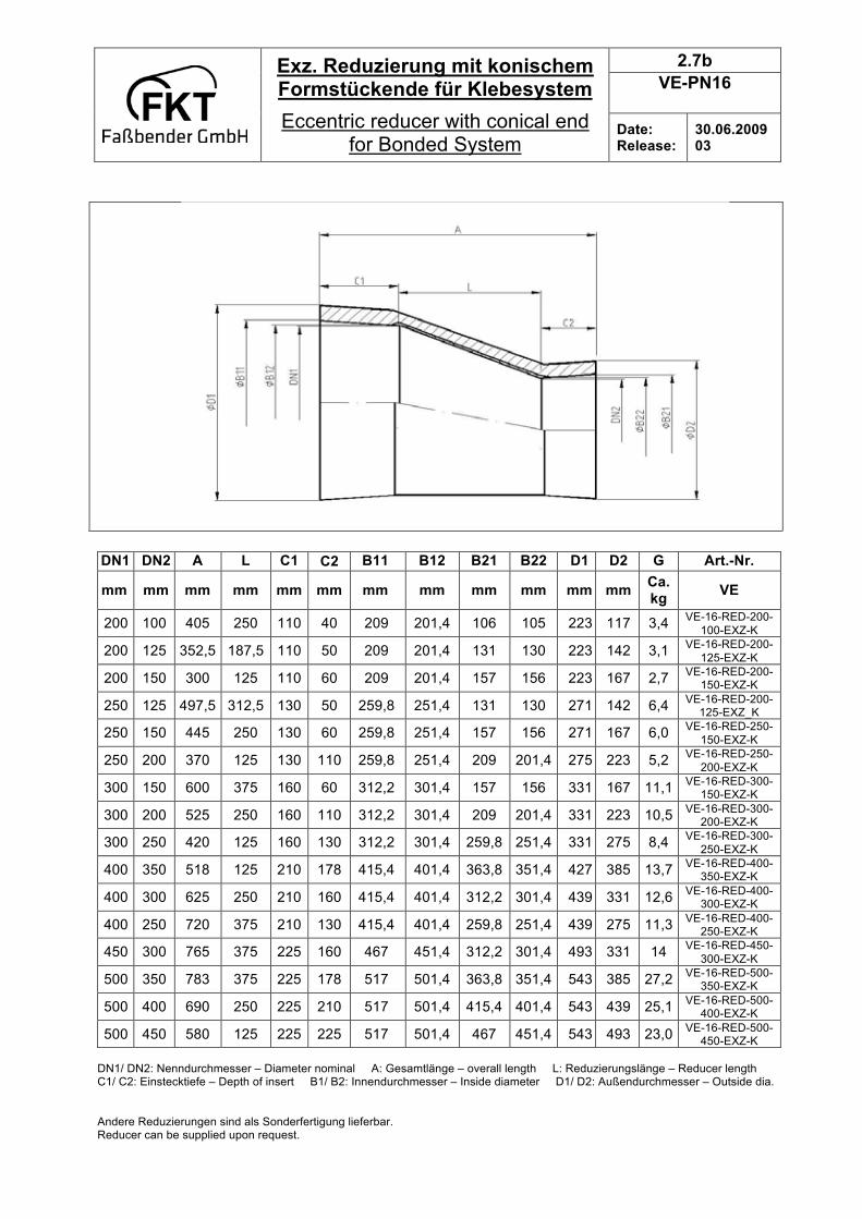
2.7b
VE-PN16
Exz. Reduzierung mit konischem Formstückende für Klebesystem
Eccentric reducer with conical end for Bonded System
Date: Release:
30.06.2009 03
DN1 DN2 A L C1 C2 B11 B12 B21 B22 D1 D2 G Art.-Nr.
mm mm mm mm mm mm mm mm mm mm mm mm Ca. kg
VE
200 100 405 250 110 40 209 201,4 106 105 223 117 3,4 VE-16-RED-200-
100-EXZ-K
200 125 352,5 187,5 110 50 209 201,4 131 130 223 142 3,1 VE-16-RED-200-
125-EXZ-K
200 150 300 125 110 60 209 201,4 157 156 223 167 2,7 VE-16-RED-200-
150-EXZ-K
250 125 497,5 312,5 130 50 259,8 251,4 131 130 271 142 6,4 VE-16-RED-200-
125-EXZ_K
250 150 445 250 130 60 259,8 251,4 157 156 271 167 6,0 VE-16-RED-250-
150-EXZ-K
250 200 370 125 130 110 259,8 251,4 209 201,4 275 223 5,2 VE-16-RED-250-
200-EXZ-K
300 150 600 375 160 60 312,2 301,4 157 156 331 167 11,1 VE-16-RED-300-
150-EXZ-K
300 200 525 250 160 110 312,2 301,4 209 201,4 331 223 10,5 VE-16-RED-300-
200-EXZ-K
300 250 420 125 160 130 312,2 301,4 259,8 251,4 331 275 8,4 VE-16-RED-300-
250-EXZ-K
400 350 518 125 210 178 415,4 401,4 363,8 351,4 427 385 13,7 VE-16-RED-400-
350-EXZ-K
400 300 625 250 210 160 415,4 401,4 312,2 301,4 439 331 12,6 VE-16-RED-400-
300-EXZ-K
400 250 720 375 210 130 415,4 401,4 259,8 251,4 439 275 11,3 VE-16-RED-400-
250-EXZ-K
450 300 765 375 225 160 467 451,4 312,2 301,4 493 331 14 VE-16-RED-450-
300-EXZ-K
500 350 783 375 225 178 517 501,4 363,8 351,4 543 385 27,2 VE-16-RED-500-
350-EXZ-K
500 400 690 250 225 210 517 501,4 415,4 401,4 543 439 25,1 VE-16-RED-500-
400-EXZ-K
500 450 580 125 225 225 517 501,4 467 451,4 543 493 23,0 VE-16-RED-500-
450-EXZ-K
DN1/ DN2: Nenndurchmesser – Diameter nominal A: Gesamtlänge – overall length L: Reduzierungslänge – Reducer length C1/ C2: Einstecktiefe – Depth of insert B1/ B2: Innendurchmesser – Inside diameter D1/ D2: Außendurchmesser – Outside dia.
Andere Reduzierungen sind als Sonderfertigung lieferbar. Reducer can be supplied upon request.
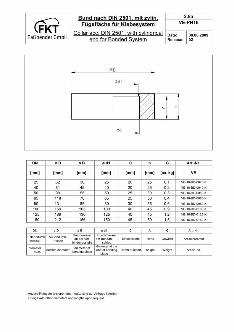
2.8a
VE-PN16
Bund nach DIN 2501, mit zylin. Fügefläche für Klebesystem
Collar acc. DIN 2501, with cylindrical end for Bonded System
Date: Release:
30.06.2009 02
DN ø D ø B ø d1 C h G Art.-Nr.
[mm]
[mm] [mm] [mm] [mm] [mm] [ca. kg] VE
25 62 30 25 20 25 0,1 VE-16-BD-0025-K
40 81 45 40 20 25 0,2 VE-16-BD-0040-K
50 99 55 50 25 30 0,3 VE-16-BD-0050-K
65 118 70 65 25 30 0,4 VE-16-BD-0065-K
80 131 85 80 30 35 0,6 VE-16-BD-0080-K
100 159 105 100 40 45 0,9 VE-16-BD-0100-K
125 189 130 125 40 45 1,2 VE-16-BD-0125-K
150 212 156 150 45 50 1,5 VE-16-BD-0150-K
DN ø D ø B ø d1 C A G Art.-Nr.
Nenndurch-messer
Außendurch- messer
Durchmesser an der Ver-
bindungsstelle
Durchmesser am Bundan-
schlag
Einstecktiefe Höhe Gewicht Artikelnummer
diameter nom.
outside diameter diameter at
bonding place
diameter at the end of bonding
place
Depth of insert height Weight Article-no.
Andere Fittingdimensionen und -maße sind auf Anfrage lieferbar.
Fittings with other diameters and lengths upon request.

2.8b
VE-PN16
Bund nach DIN 2501, mit koni. Fügefläche für Klebesystem
Collar acc. DIN 2501 with conical end for Bonded System
Date: Release:
30.06.2009 02
DN ø D ø B1 ø B2 C h G Art.-Nr.
[mm]
[mm] [mm] [mm] [mm] [mm] [ca. kg] VE
200 265 208,0 204,8 55 55 2,3 VE-16-BD-0200-K
250 320 259,6 255,7 75 75 4,0 VE-16-BD-0250-K
300 370 311,6 306,7 75 75 4,6 VE-16-BD-0300-K
350 430 363,8 358,0 85 85 7,4 VE-16-BD-0350-K
400 485 415,4 408,9 95 95 10,0 VE-16-BD-0400-K
450 535 467,0 460,2 100 100 11,7 VE-16-BD-0450-K
500 600 517,0 509,1 115 115 15,7 VE-16-BD-0500-K
DN ø D ø B1 ø B2 C h G Art.-Nr.
Nenndurch-messer
Außendurch- messer
Durchmesser 1 an der Ver-
bindungsstelle
Durchmesser 2 an der Ver-
bindungsstelle
Einstecktiefe Höhe Gewicht Artikelnummer
diameter nom.
outside diameter diameter 1 at bonding place
diameter 2 at bonding place
Depth of insert height Weight Article-no.
Andere Fittingdimensionen und -maße sind auf Anfrage lieferbar.
Fittings with other diameters and lengths upon request.
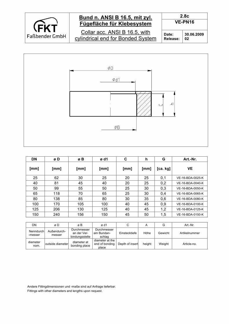
2.8c
VE-PN16
Bund n. ANSI B 16.5, mit zyl. Fügefläche für Klebesystem
Collar acc. ANSI B 16.5, with cylindrical end for Bonded System
Date: Release:
30.06.2009 02
DN ø D ø B ø d1 C h G Art.-Nr.
[mm]
[mm] [mm] [mm] [mm] [mm] [ca. kg] VE
25 62 30 25 20 25 0,1 VE-16-BDA-0025-K
40 81 45 40 20 25 0,2 VE-16-BDA-0040-K
50 99 55 50 25 30 0,3 VE-16-BDA-0050-K
65 118 70 65 25 30 0,4 VE-16-BDA-0065-K
80 138 85 80 30 35 0,6 VE-16-BDA-0080-K
100 170 105 100 40 45 0,9 VE-16-BDA-0100-K
125 206 130 125 40 45 1,2 VE-16-BDA-0125-K
150 240 156 150 45 50 1,5 VE-16-BDA-0150-K
DN ø D ø B ø d1 C A G Art.-Nr.
Nenndurch-messer
Außendurch- messer
Durchmesser an der Ver-
bindungsstelle
Durchmesser am Bundan-
schlag
Einstecktiefe Höhe Gewicht Artikelnummer
diameter nom.
outside diameter diameter at
bonding place
diameter at the end of bonding
place
Depth of insert height Weight Article-no.
Andere Fittingdimensionen und -maße sind auf Anfrage lieferbar.
Fittings with other diameters and lengths upon request.
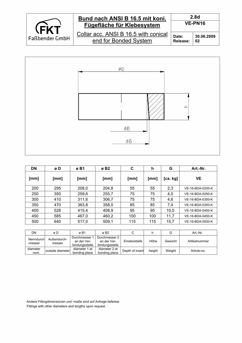
2.8d
VE-PN16
Bund nach ANSI B 16.5 mit koni. Fügefläche für Klebesystem
Collar acc. ANSI B 16.5 with conical end for Bonded System
Date: Release:
30.06.2009 02
DN ø D ø B1 ø B2 C h G Art.-Nr.
[mm]
[mm] [mm] [mm] [mm] [mm] [ca. kg] VE
200 295 208,0 204,8 55 55 2,3 VE-16-BDA-0200-K
250 350 259,6 255,7 75 75 4,0 VE-16-BDA-0250-K
300 410 311,6 306,7 75 75 4,6 VE-16-BDA-0300-K
350 470 363,8 358,0 85 85 7,4 VE-16-BDA-0350-K
400 528 415,4 408,9 95 95 10,0 VE-16-BDA-0400-K
450 585 467,0 460,2 100 100 11,7 VE-16-BDA-0450-K
500 640 517,0 509,1 115 115 15,7 VE-16-BDA-0500-K
DN ø D ø B1 ø B2 C h G Art.-Nr.
Nenndurch
-messer
Außendurch-
messer
Durchmesser 1
an der Ver- bindungsstelle
Durchmesser 2
an der Ver- bindungsstelle
Einstecktiefe Höhe Gewicht Artikelnummer
diameter
nom. outside diameter
diameter 1 at
bonding place
diameter 2 at
bonding place Depth of insert height Weight Article-no.
Andere Fittingdimensionen und -maße sind auf Anfrage lieferbar.
Fittings with other diameters and lengths upon request.

2.9a
VE-PN16
Stahllosflansch nach DIN 2501, PN16, für Klebesystem
Steelflange according DIN 2501, PN16, for Bonded system
Date: Release:
30.06.2009 02
DN
[mm]
D
[mm]
d1
[mm]
b
[mm]
k
[mm]
Anz./ Number
of screws
d2
[mm]
G
[ca. kg]
Art.-Nr.
25 115 36 16 85 4 14 1,1 PN-16-SLFL-0025-K
40 150 54 16 110 4 18 1,8 PN-16-SLFL-0040-K
50 165 65 16 125 4 18 2,1 PN-16-SLFL-0050-K
65 185 81 16 145 4 18 2,6 PN-16-SLFL-0065-K
80 200 108 18 160 8 18 3,2 PN-16-SLFL-0080-K
100 220 135 18 180 8 18 3,5 PN-16-SLFL-0100-K
125 250 158 18 210 8 18 4,3 PN-16-SLFL-0125-K
150 285 188 18 240 8 22 5,2 PN-16-SLFL-0150-K
200 340 238 20 295 12 22 7,4 PN-16-SLFL-0200-K
250 405 294 24 355 12 26 12,0 PN-16-SLFL-0250-K
300 460 345 28 410 12 26 17,0 PN-16-SLFL-0300-K
350 520 395 32 470 16 26 23,5 PN-16-SLFL-0350-K
400 580 448 36 525 16 30 31,1 PN-16-SLFL-0400-K
450 640 480 40 585 20 30 40,3 PN-16-SLFL-0450-K
500 715 550 44 650 20 33 50,7 PN-16-SLFL-0500-K
DN: Nenndurchmesser – Diameter nominal D: Außendurchmesser – Outside diameter d1: Innendurchm. – Inside diameter b: Flanschdicke – Flange thickness K: Lochkreisdurchmesser – Bolt circle diameter d2: Bohrungsdurchm. – Drilling diameter
Alle Anschlussmaße nach DIN 2501 und für den Nenndruck 16 bar. Auf Anfrage lieferbar: - Flansche in versch. Werkstoffen (z.B. C 22.8) / die benötigten Dichtungen und Schraubenverbindungen - mit beschichteten Oberflächen
All measure according to DIN 2501 and constructed for working pressure of 16 bar. Upon request can be delivered: flanges in different kinds of materials (example: C 22.8)/ gaskets and bolting sets / different coatings
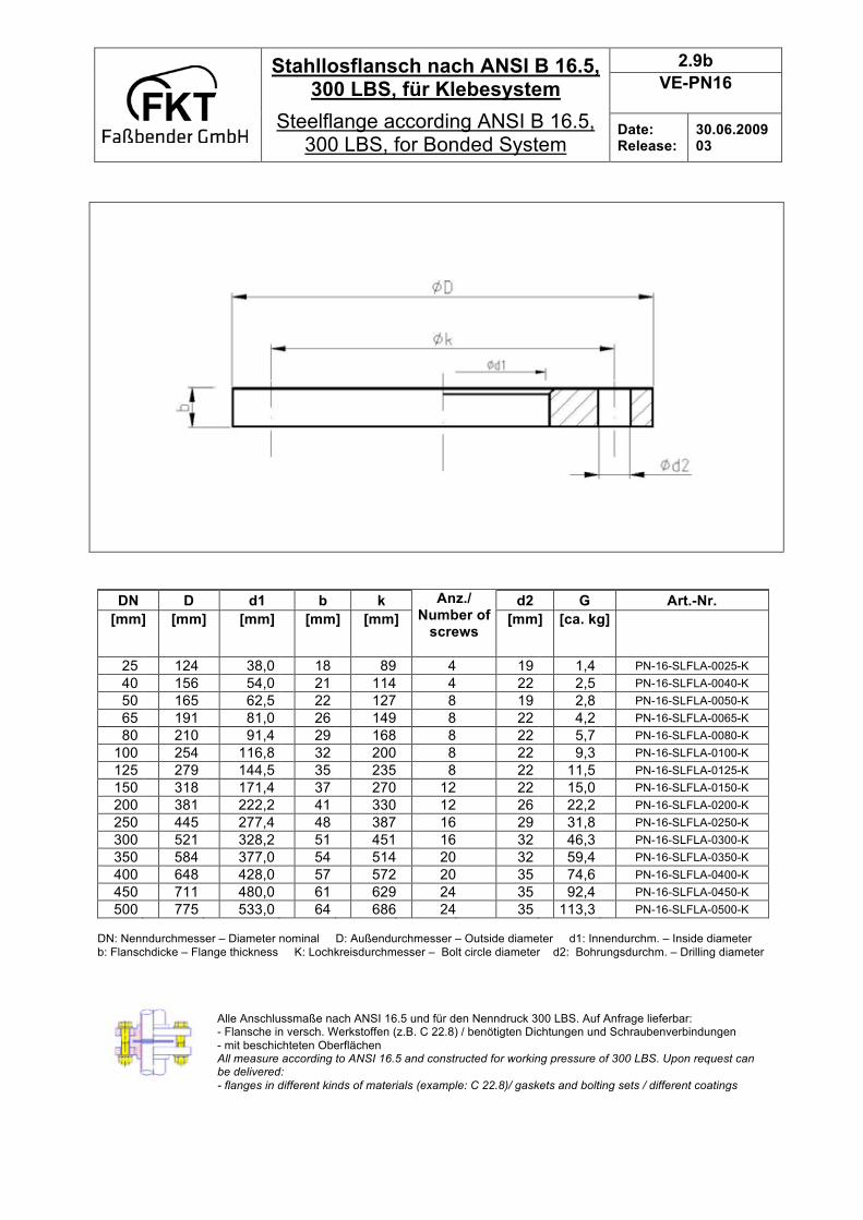
2.9b
VE-PN16
Stahllosflansch nach ANSI B 16.5, 300 LBS, für Klebesystem
Steelflange according ANSI B 16.5, 300 LBS, for Bonded System
Date: Release:
30.06.2009 03
DN
[mm]
D
[mm]
d1
[mm]
b
[mm]
k
[mm]
Anz./ Number of
screws
d2
[mm]
G
[ca. kg]
Art.-Nr.
25 124 38,0 18 89 4 19 1,4 PN-16-SLFLA-0025-K
40 156 54,0 21 114 4 22 2,5 PN-16-SLFLA-0040-K
50 165 62,5 22 127 8 19 2,8 PN-16-SLFLA-0050-K
65 191 81,0 26 149 8 22 4,2 PN-16-SLFLA-0065-K
80 210 91,4 29 168 8 22 5,7 PN-16-SLFLA-0080-K
100 254 116,8 32 200 8 22 9,3 PN-16-SLFLA-0100-K
125 279 144,5 35 235 8 22 11,5 PN-16-SLFLA-0125-K
150 318 171,4 37 270 12 22 15,0 PN-16-SLFLA-0150-K
200 381 222,2 41 330 12 26 22,2 PN-16-SLFLA-0200-K
250 445 277,4 48 387 16 29 31,8 PN-16-SLFLA-0250-K
300 521 328,2 51 451 16 32 46,3 PN-16-SLFLA-0300-K
350 584 377,0 54 514 20 32 59,4 PN-16-SLFLA-0350-K
400 648 428,0 57 572 20 35 74,6 PN-16-SLFLA-0400-K
450 711 480,0 61 629 24 35 92,4 PN-16-SLFLA-0450-K
500 775 533,0 64 686 24 35 113,3 PN-16-SLFLA-0500-K DN: Nenndurchmesser – Diameter nominal D: Außendurchmesser – Outside diameter d1: Innendurchm. – Inside diameter
b: Flanschdicke – Flange thickness K: Lochkreisdurchmesser – Bolt circle diameter d2: Bohrungsdurchm. – Drilling diameter
Alle Anschlussmaße nach ANSI 16.5 und für den Nenndruck 300 LBS. Auf Anfrage lieferbar: - Flansche in versch. Werkstoffen (z.B. C 22.8) / benötigten Dichtungen und Schraubenverbindungen
- mit beschichteten Oberflächen All measure according to ANSI 16.5 and constructed for working pressure of 300 LBS. Upon request can be delivered:
- flanges in different kinds of materials (example: C 22.8)/ gaskets and bolting sets / different coatings
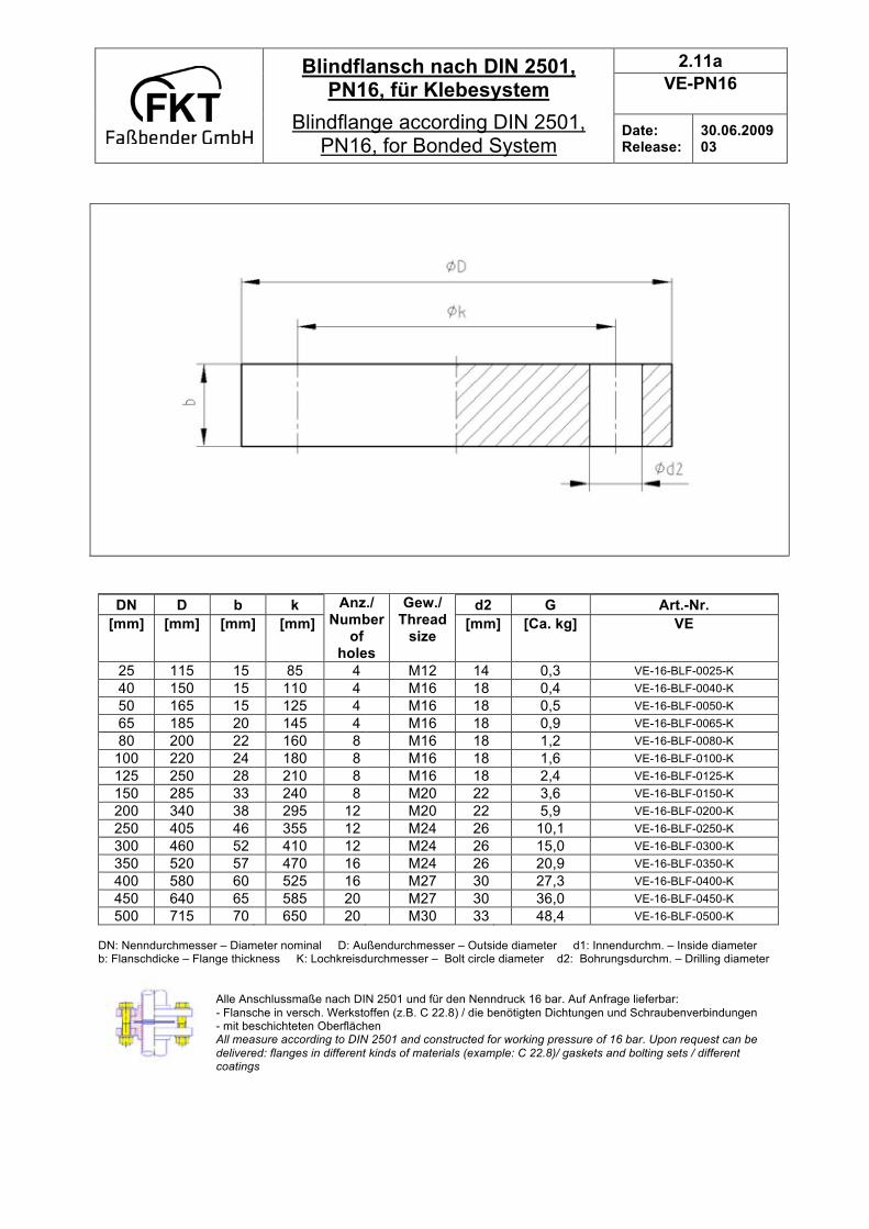
2.11a
VE-PN16
Blindflansch nach DIN 2501, PN16, für Klebesystem
Blindflange according DIN 2501, PN16, for Bonded System
Date: Release:
30.06.2009 03
DN
[mm]
D
[mm]
b
[mm]
k
[mm]
Anz./ Number
of holes
Gew./ Thread
size
d2
[mm]
G
[Ca. kg]
Art.-Nr.
VE
25 115 15 85 4 M12 14 0,3 VE-16-BLF-0025-K
40 150 15 110 4 M16 18 0,4 VE-16-BLF-0040-K
50 165 15 125 4 M16 18 0,5 VE-16-BLF-0050-K
65 185 20 145 4 M16 18 0,9 VE-16-BLF-0065-K
80 200 22 160 8 M16 18 1,2 VE-16-BLF-0080-K
100 220 24 180 8 M16 18 1,6 VE-16-BLF-0100-K
125 250 28 210 8 M16 18 2,4 VE-16-BLF-0125-K
150 285 33 240 8 M20 22 3,6 VE-16-BLF-0150-K
200 340 38 295 12 M20 22 5,9 VE-16-BLF-0200-K
250 405 46 355 12 M24 26 10,1 VE-16-BLF-0250-K
300 460 52 410 12 M24 26 15,0 VE-16-BLF-0300-K
350 520 57 470 16 M24 26 20,9 VE-16-BLF-0350-K
400 580 60 525 16 M27 30 27,3 VE-16-BLF-0400-K
450 640 65 585 20 M27 30 36,0 VE-16-BLF-0450-K
500 715 70 650 20 M30 33 48,4 VE-16-BLF-0500-K DN: Nenndurchmesser – Diameter nominal D: Außendurchmesser – Outside diameter d1: Innendurchm. – Inside diameter b: Flanschdicke – Flange thickness K: Lochkreisdurchmesser – Bolt circle diameter d2: Bohrungsdurchm. – Drilling diameter
Alle Anschlussmaße nach DIN 2501 und für den Nenndruck 16 bar. Auf Anfrage lieferbar:
- Flansche in versch. Werkstoffen (z.B. C 22.8) / die benötigten Dichtungen und Schraubenverbindungen - mit beschichteten Oberflächen All measure according to DIN 2501 and constructed for working pressure of 16 bar. Upon request can be
delivered: flanges in different kinds of materials (example: C 22.8)/ gaskets and bolting sets / different coatings
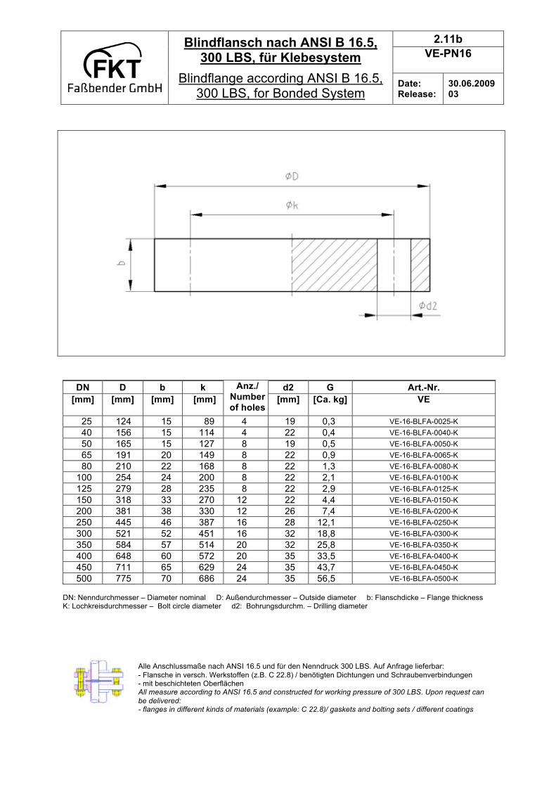
2.11b
VE-PN16
Blindflansch nach ANSI B 16.5, 300 LBS, für Klebesystem
Blindflange according ANSI B 16.5, 300 LBS, for Bonded System
Date: Release:
30.06.2009 03
DN
[mm]
D
[mm]
b
[mm]
k
[mm]
Anz./ Number of holes
d2
[mm]
G
[Ca. kg]
Art.-Nr.
VE
25 124 15 89 4 19 0,3 VE-16-BLFA-0025-K
40 156 15 114 4 22 0,4 VE-16-BLFA-0040-K
50 165 15 127 8 19 0,5 VE-16-BLFA-0050-K
65 191 20 149 8 22 0,9 VE-16-BLFA-0065-K
80 210 22 168 8 22 1,3 VE-16-BLFA-0080-K
100 254 24 200 8 22 2,1 VE-16-BLFA-0100-K
125 279 28 235 8 22 2,9 VE-16-BLFA-0125-K
150 318 33 270 12 22 4,4 VE-16-BLFA-0150-K
200 381 38 330 12 26 7,4 VE-16-BLFA-0200-K
250 445 46 387 16 28 12,1 VE-16-BLFA-0250-K
300 521 52 451 16 32 18,8 VE-16-BLFA-0300-K
350 584 57 514 20 32 25,8 VE-16-BLFA-0350-K
400 648 60 572 20 35 33,5 VE-16-BLFA-0400-K
450 711 65 629 24 35 43,7 VE-16-BLFA-0450-K
500 775 70 686 24 35 56,5 VE-16-BLFA-0500-K
DN: Nenndurchmesser – Diameter nominal D: Außendurchmesser – Outside diameter b: Flanschdicke – Flange thickness K: Lochkreisdurchmesser – Bolt circle diameter d2: Bohrungsdurchm. – Drilling diameter
Alle Anschlussmaße nach ANSI 16.5 und für den Nenndruck 300 LBS. Auf Anfrage lieferbar:
- Flansche in versch. Werkstoffen (z.B. C 22.8) / benötigten Dichtungen und Schraubenverbindungen - mit beschichteten Oberflächen All measure according to ANSI 16.5 and constructed for working pressure of 300 LBS. Upon request can
be delivered: - flanges in different kinds of materials (example: C 22.8)/ gaskets and bolting sets / different coatings

2.14a
VE-PN16
Rohrmuffe mit zylindrischer Fügefläche für Klebesystem
Coupling with cylindrical end for Bonded System
Date: Release:
30.06.2009 02
DN ø D ø B C A G Art.-Nr.
[mm]
[mm] [mm] [mm] [mm] [ca. kg] VE
25 42 30 25 55 0,1 VE-16-MU-0025-K
40 57 45 25 55 0,1 VE-16-MU-0040-K
50 67 55 25 55 0,1 VE-16-MU-0050-K
65 82 70 25 55 0,1 VE-16-MU-0065-K
80 97 85 35 75 0,2 VE-16-MU-0080-K
100 117 105 40 85 0,3 VE-16-MU-0100-K
125 142 130 50 105 0,5 VE-16-MU-0125-K
150 167 155 60 125 0,5 VE-16-MU-0150-K
DN ø D ø B C A G Art.-Nr.
Nenndurch-messer
Außen- durchm.
Durchmesser an der Ver-
bindungsstelle
Einstecktiefe Maß A Gewicht Artikelnummer
diameter nom.
Outside diameter
diameter at the bonding place
Depth of insert
measure A Weight Article-no.
Andere Fittingdimensionen und -maße sind auf Anfrage lieferbar. Fittings with other diameters and lengths upon request.

2.14b
VE-PN16
Rohrmuffe mit konischer Fügefläche für Klebesystem
Coupling with conical end for Bonded System
Date: Release:
30.06.2009 02
DN ø D ø B1 ø B2 C A G Art.-Nr.
[mm]
[mm] [mm] [mm] [mm] [mm] [ca. kg] VE
200 223 209,0 201,4 110 221 1,9 VE-16-MU-0200-K
250 275 259,8 251,4 130 261 2,8 VE-16-MU-0250-K
300 331 312,2 301,4 160 321 5,3 VE-16-MU-0300-K
350 385 363,8 351,4 178 357 8,0 VE-16-MU-0350-K
400 439 415,4 401,4 210 421 11,5 VE-16-MU-0400-K
450 493 467,0 451,4 225 451 15,9 VE-16-MU-0450-K
500 543 517,0 501,4 225 451 17,6 VE-16-MU-0500-K
DN ø D ø B1 ø B2 C A G Art.-Nr.
Nenndurch
-messer
Außendurch-
messer
Durchmesser 1
an der Ver- bindungsstelle
Durchmesser 2
an der Ver- bindungsstelle
Einstecktiefe Maß A Gewicht Artikelnummer
diameter
nom. outside diameter
diameter 1 at
bonding place
diameter 2 at
bonding place Depth of insert measure A Weight Article-no.
Andere Fittingdimensionen und -maße sind auf Anfrage lieferbar.
Fittings with other diameters and lengths upon request.