Well control equipment - RGN
82
Well control equipment Matanović Davorin, professor
Transcript of Well control equipment - RGN

Well control equipment
Matanović Davorin, professor

Blowout Preventers
Blowout preventers (BOPs), in conjunction with other equipment and techniques, are used to close the well in and allow the crew to control a kick before it becomes a blowout.
Blowout preventer equipment should be designed to:
1. Close the top of the hole.
2. Control the release of fluids.
3. Permit pumping into the hole.
4. Allow movement of the inner string of pipe.

Blowout Preventers
These requirements mean that there;must be enough casing in the well to provide an anchor for the wellhead equipment,
there must be provision for equipment to close the hole with or without pipe in well,
the equipment must provide for the attachment of lines for bleeding off pressure, and
it must allow pumping into the working string or annulus.
Blowout Preventers
Basic types of blowout preventers on drilling rig are:
annular preventers
ram preventers
rotational preventers and
diverters

Blowout Preventers
The recommended component codes for designation of BOP stack arrangements are as follows:

Blowout Preventers
BOP components are typically described upward from the uppermost piece of the permanent wellhead equipment, or from the bottom of the BOP stack:
10K – 13 5/8 – SRRA
This BOP stack would be rated 10000 psi (69 MPa) working pressure, would have a through bore of 13 5/8 inches (34,61 cm), and would be arranged according to picture.

Blowout Preventers
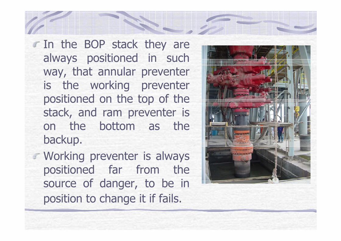
In the BOP stack they are always positioned in such way, that annular preventer is the working preventer positioned on the top of the stack, and ram preventer is on the bottom as the backup.
Working preventer is always positioned far from the source of danger, to be in
position to change it if fails.

BOPs Rating
Any assembly of blowout prevention equipment can be rated by the lowest pressure item in the hookup;
whether it is casing,
casing head,
preventers, or
other fitting primarily exposed to well pressure.

BOPs Rating
The bursting pressure of the casing will often be the determining factor for rating the working pressure of the assembly.
API Bulletin D 13 gives the pressure ratings for blowout preventer equipment:

BOPs Rating
extreme pressure
1034 (15000)15 M
high pressure689 (10000)10 M
medium pressure
345 (5000)5 M
low pressure207 (3000)3 M
light duty138 (2000)2 M
Service Condition
Working pressure 105 Pa (psi)
API Class
Annular-type
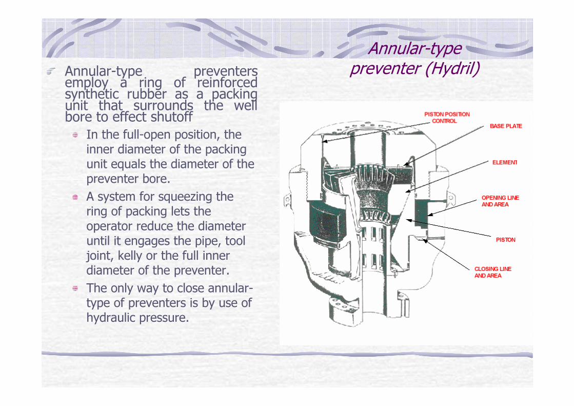
preventer (Hydril)Annular-type preventers employ a ring of reinforced synthetic rubber as a packing unit that surrounds the well bore to effect shutoff
In the full-open position, the inner diameter of the packing unit equals the diameter of the preventer bore.
A system for squeezing the ring of packing lets the operator reduce the diameter until it engages the pipe, tool joint, kelly or the full inner diameter of the preventer.
The only way to close annular-type of preventers is by use of hydraulic pressure.

Annular-typepreventer (Hydril)Cutaway view of the blowout
preventer can help to show the main parts:
body,cover,packing element, andoperating cylinder.
The pressure of hydraulic fluid introduced under the piston (A) produces lifting power that raises the operating cylinder.The tapered bowl of operating cylinder compresses the packing element to make the annular shutoff.Pumping the hydraulic fluid in opposite direction (B) forces the operating cylinder downward, thus permitting the packing unit to open by expansion.
A
B

Annular-typepreventer (Hydril)
Although initial closure of the packing unit is obtained by hydraulic pressure from an external source, well pressure will increase sealing effect and thus insure positive closure under high well pressure.The preventer is normally operated by a fluid pressure of 103�105 Pa (1500 psi).
A pressure regulator should be employed to insure the lowest closing pressure to permit slight leakage of well fluid around the drill pipe when rotating or stripping in or out of the hole.A small amount of fluid leaking past the pipe will lubricate and cool the packing unit.

Annular-type preventer(Shaffer)

The pressure of hydraulic fluid introduced under the piston (A) produces lifting power that raises the operating cylinder.The tapered bowl of operating cylinder compresses the packing element to make the annular shutoff.
A

Packing element
Packing element (Hydril)
Note the steel finger inserts which strengthen and reinforce the resilient packing material.
Packing element (Shaffer)

Natural rubber is used with water based mud, and working temperatures from –35 °C to 107 °C.
High duration and reliability.
Identification code is R or NR with serial number and black color on the upper edge.
Nitrile rubber (synthetic components in natural rubber), is used with oil based muds or with mudsthat have oil based additives,and working temperatures from – 7 °C to 88 °C.
Identification code is S or NBR with serial number and red color on the upper edge.
Neoprene rubber is used with oil based muds and low temperatures from – 35 °C to 77 °C.
Higher duration than natural rubber with better elasticity on lower temperatures than nitrilerubbers.
Identification code is N or CR with serial numberand green color on the upper edge.

Ram-typepreventers
They close the annular space outside the string of pipe in a well or open hole, by moving rams from a retracted position clear of the bore into a position where they close around the pipe.
Rams operate in pairs and seal space below them closed.

Ram-typepreventers
Pipe rams are provided with semicircular openings which match the diameter of the pipe sizes for which they are designed.
It is absolutely vital that the pipe rams in a preventer fit the drill pipe or tubing in the use, and all concerned must be certain in this regard at all times.
If more than one size of drill pipe is in the hole, most operators require a second ram preventer in the stack.

Ram-type preventers
Blank units which will close on the open hole are commonly termed “blind” rams.
Blind rams will flatten drill pipe or tubing if they are inadvertently closed in them, and the driller should always be certain not to operate the blind rams when the pipe is in the hole.
Ram-type preventers were originally manually operated, but most preventers of this type today are closed and opened by hydraulicmeans, using fluid that is under 35�105 Pa (500 psi) to 103�105 Pa (1500 psi) of pressure.
Most ram-type preventers are provided with screws to lock the rams in the closed position.
Manually operated preventers are similar to hydraulic units, except for the hydraulic cylinders.

Shaffer ram-type hydraulic blowout preventer with automatic lock
On the picture (left) there is the closing system with ram in opened position, and on the picture (right) is the same system in fully closed position.
Closingelement
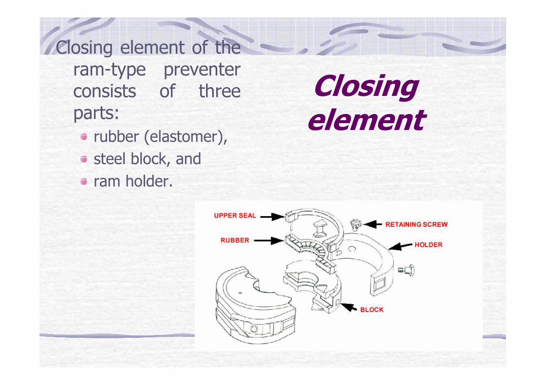
Closing element of the ram-type preventer consists of three parts:
rubber (elastomer),
steel block, and
ram holder.

It is also possible (available), to use rams that can be closed around different drill pipe diameters: from 88,9 mm (3 ½˝) to 127,0 mm (5");
That is just to avoid the necessity to change the rams in preventer, when the drill pipe diameter is changed.
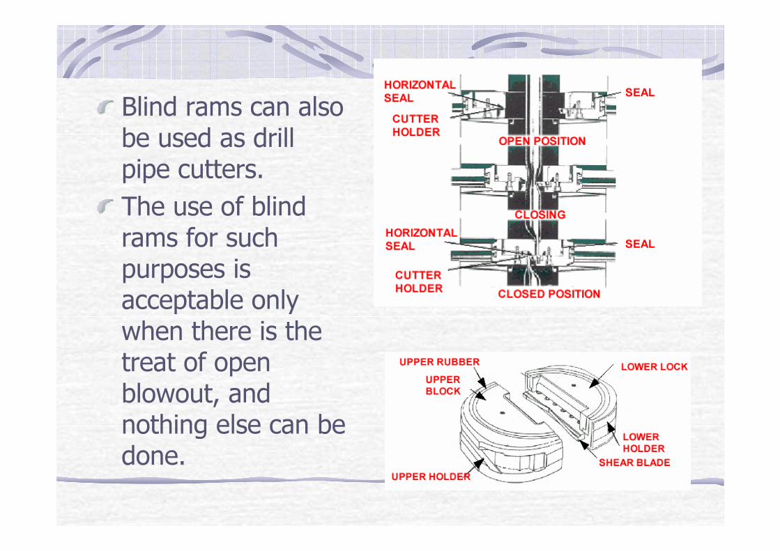
Blind rams can also be used as drill pipe cutters.
The use of blind rams for such purposes is acceptable only when there is the treat of open blowout, and nothing else can be done.

Rotationalpreventers
Rotational preventers are used:
For drilling in layers that are suspected to cause possible kick off.
When drilling on the balance or under balanced (drilling the rocks of great permeability or porosity; to avoid pollution with mud).
When using indirect circulation.
When the drilling is done using air or gas.

Rotationil preventers
Rotational preventer is always positioned at the top of the stack above annular preventer.
It is used when differential pressure at the wellhead does not exceed 34,5�105
Pa (500 PSI),
and in such situation it must enable manipulation (withdrawing and embedding) and rotation of drill stem through the closed working (sealing) element.

Rotational part of the preventer is mounted on the drill pipe by use of unique prong, and is posted on the working floor.When needed, the rotational head is connected to the housing, mounted on the top of annular preventer.
Rotational sleeve is rotated by the rotation of the kelly, and is at the same time rotating the working rubber element on the cylindrical bearing.

DivertersDiverters as the name says are used to, direct eventualinvaded higher pressure fluid from the well, to the cleaning and reservoir system, and not to danger the workers on the working platform of the derrick.
That is accomplished by closing the working sealing element of the diverter and opening diverter pipe lines whose diameter is from 101,6 mm (4") to 304,8 mm (12").
There are usually two relief lines, and one that is opened must be always in the direction that provide that gas or dangerous fluid will be carried away of the rig floor.

The line is opened at the same moment the working sealing element is closed.
It is important because failing to do so it is possible to fracture shallow rocks and the gas or high pressure fluid can rupture to the surface near or far from the rig uncontrolled.
That is especially dangerous off-shore when using the platform that is standing on the see-bottom on the legs, because the material can be washed over below one leg, and the platform can turn over.

Diverters are mainly used in off-shore drilling.
On shore they are rare in use: mainly in drilling for the conductor when the well is to be with total depth over 6000 m.
That is because there is not other preventer that will enable the passage of the bit of 660,4 mm (26“) diameter, that is used to drill the hole for casingwith diameter of 508 mm (20“).

Inside preventers
An:kelly cock
inside blowout preventer,
drill pipe float valve, or
drop in check valve
should be available for use when stripping the drill string into or out of the hole.
The valve(s), sub(s), or profile nipple should be equipped to screw into any drill string member in use.

Kelly valves (kelly cocks)
An upper kelly valve is installed between the swivel and the kelly.
A lower kelly valve is installed imediatellybelow the kelly.
Upper kelly has on the top the left-hand screw to avoid uncontrolled screw of, and on the bottom there will be a right-hand screw.

Inside Blowout preventer
The inside blowout preventer protects the rotary swivel, drilling hose, standpipe and mud pumps when a kick occurs through the drill string.
It will effectively seal against the pressures up to 69 MPa.
Permits downward flow of circulation fluid through the drill pipe while preventing upward flow after circulation stops.
Always on the working floor near the rotary table.

In Shaffer type kelly valve, closingelement is a (roller)cylinder.
Sealing is achieved by rubber to metal contact.

Drill string safety valveA spare drill pipe safety valve should be readily available (i.e. stored in open position with wrench accessible) on the rig floor at all times.
This valve or valves should be equipped to screw into any drill string member in use.
The outside diameter of the drill pipe safety valve should be suitable for running in the hole.

Drill string float valves
A float valve is placed in the drill string to prevent upward flow of fluid or gas inside the drill string.
This is a special type of back pressure check valve.
When in good working order it will prohibit backflow and a potential blowout through the drill string.

The drill string float valve is usually placed in the lower-most portion of the drill string, between two drill collars or between the drill bit and drill collar.
Since the float valve prevents the drill string from being filled with fluid through the bit as it is run into the hole, the drill string must be filled from the top, at the drill floor, to prevent collapse of the drill pipe.

Flapper-type float valve
The flapper-type float valve offers the advantage of having the opening through the valve that is approximately the same inside diameter as that of the tool joint.
This valve will permit the passage of balls, or go-devils, which may be required for operation of tools inside the drill string below the float valve.

Spring-loaded float valves
The spring-loaded ball, or dart, and seat float valve offers the advantage of an instantaneous and positive shut off of backflow through the drill string.
These valves are not full-bore and thus cannot sustain long duration or high volume pumping of drilling or kill fluid.
A wireline retrievable valve that seals in a profiled body that has an opening approximately the same inside diameter as that of tool joint may be used to provide a full-open access, if needed.

Well head
• The wellhead includes all equipment placed on top of the well to support tubulars, provide seals, and control the paths and flow rates of fluids.− All wellheads include at
least;− one casing head and casing
hanger,− a tubing head and tubing
hanger, and a Christmas tree.

Well head• Casing heads are
attached to surface casing or to another casing head to provide a hanging point for the next string of casing.
− If there is one casing head, it is welded or screwed (depending on diameter) to the surface casing, and the production casing is hung from it.

Well head− If more than one casing string is used inside the surface casing, then more than one casing head may be needed.
− An intermediate casing head may be added with each new casing string until the production casing has been hung.

Well headThe top of a casing head has a cone-shaped bowl that holds the casing hanger.
A casing hanger is a set of slips that grips and supports a casing string.Metal and rubber packing rings fit over the slips to complete the casing hanger assembly and provide an annular seal.Threaded or flanged outlets on the side of the casing head allow access to the sealed annulus for pressure gauges that warn of casing leaks.

Three types of end and outlet flanges are controlled by API Spec. 6A. (10-4)
That are 6B and 6BX flanges that can be used as integral, blind or weld neck flanges.
Type 6B may also be used as threaded flanges.
Some type of 6BX blind flanges may also be used as test flanges.
The third type – segmented flanges are used on dual completion wells and are integral with the equipment.
X – diameter of hub, m
B – maximum bore, m
T – flange thickness, m
K – diameter of raised face, m
BC – diameter of bolt circle, m
OD – outside flange diameter, m

The bolt length is established using:
LCSB
=A+n
Where:
LCSB
– calculated stud length (effective thread length, excluding end points), m
LSSB
- specified stud bolt length (which is LCSB rounded off to the nearest commercially available length), m

A=2⋅(T+0,5⋅t+d)+S A - stud bolt length exclusive of negative length tolerance, m
T – flange thickness, m
t – plus tolerance for flange thickness, m
d – nut thickness (equals nominal bolt diameter), m
S – flange face standoff (for BX assemblies it is zero), m
n – negative tolerance on bolt length : 1,5875 mm (1/16") for lengths up to 304,8mm (12"); 3,175 mm (1/8") for lengths over304,8 mm (12") to 457,2 mm(18"); 6,35 mm (1/4") for lengths over457,2 mm (18"), m

Type R and RX gaskets are used on 6B flanges.
Only type BX gaskets are to be used with 6BX flanges.
RX and BX provide a pressure energized seal but are not interchangeable .
E – groove depth, m
F – groove width, m
R2
– radius in groove, m
R1
– radius in ring (octagonal ring), m
H,B – ring height
P – standard ring or groove diameter, m
A – width of ring, m
C – width of flat (octagonal ring), m
Gasket and groove type "R"

Note! The pressure passage hole in the RX ring has a hole whose centerline is located at midpoint of dimension ˝C˝. Hole diameter is 1,524 mm (0,06 in) for rings RX-82 to RX-85, 2,286 mm (0,09 in) for rings RX-86 and RX-87, and 3,048 mm (0,12 in) for rings RX-88 to RX-91.(10-27)
Ring and groove "RX" Ring and groove "BX"

Sealing systemsPack off system consists of lip seal packing and two metal packing supports.
Each crossover spool, multistage crossover spool, crossover adapter; shall have at least one restricted area pack off.

Testing and Maintenance of surface BOP stack
and well control equipment
The purpose for various test programs on drilling well control equipment is to verify:
1. That specific functions are operationally ready.
2. The pressure integrity of the installed equipment.
3. The control system and BOP compatibility

Testing and Maintenance of surface BOP stack
and well control equipment
All operational components of the BOP equipment should be functioned at least once a weak to verify the component’s intended operations, Function tests may or may not include pressure tests.
They should be alternated from the driller’s panel and from mini-remote panels, if on location.
Actuation times should be recorded as a data base for evaluating trends.

When testing BOP stack the hole is separated by the use of so called “cup tester”.

Pressure tests
All blowout prevention components that my be exposed to well pressure should be tested first to a low pressure of 1,38 to 2,1 MPa (200 to 300 psi) and then to a high pressure.
When performing the low pressure test, do not apply a higher pressure and bleed down to the low test pressure.
A stable low test pressure should be maintained for at least 5 minutes.

Pressure tests
The initial high pressure test on components that could be exposed to well pressure (BOP stack, choke manifold and choke lines) should be to the rated working pressure of the ram BOP’s or to the rated working pressure of the wellhead that the stack is installed on, whichever is lower.
Initial pressure tests are defined as those tests that should be performed on location before the well is spaded or before the equipment is put into operational service.

Pressure tests
Diverter systems are typically pressure tested to a low pressure only.
Annular BOPs, with a joint of drill pipe installed, may be tested to the pressure applied to the ram BOPs or to a minimum of 70% of the annular preventer working pressure, whichever is the lesser

Pressure tests
The lower kelly valves, kelly, kelly cock, drill pipe safety valves, inside BOPs and top drive safety valves, should be tested with water pressure applied from below to a low pressure of 1,38 to 2,1 MPa(200 to 300 psi) and then to the rated working pressure.

Pressure tests
For instance: The producer of ram-type preventer (18 3/4“; 15000 psi) defines test pressures as:
around drill pipes 800 to 1100 psi; from 5,5 to 7,6 MPa,
full bore rams 800 to 1100 psi; from 5,5 to 7,6 MPa,
cutting rams 1100 to 1400 psi; od 7,6 to 9,7 MPa.

Pressure tests
Subsequent high pressure tests on the well control components should be to a pressure greater than the maximum anticipated surface pressure, but not to exceed the working pressure of the ram BOPs.
The maximum anticipated pressure should be determined by the operator based on specific anticipated well conditions..

The pressure test performed on hydraulic chambers of annular BOPs, connectors, hydraulic lines and manifolds, should not exceed (should be at least) 10,3 MPa (1500 psi).
Initial pressure tests on hydraulic chambers of ram BOPs and hydraulically operated valves should be to the maximum operating pressure recommended by the manufacturer.

For annular preventers closing pressures differ because of the higher closing area.
Figure shows closing pressures for annular preventers depending on working pressure and closing area (full closing or around specific pipe diameter).

Pressure testing of an annular preventer

Pressure testing of an ram-type preventer, closing around the pipe body.

Hydraulic control fluids
Preventers are activated by the use of special hydraulic control fluid. The fluid must:
not freeze on low temperatures (temperature range from 84 °C to –46 °C)
lubricate moving parts and avoid wearing out
not cause corrosion
disperse in salt or fresh water and not pollute or contaminate.
For such purpose it is possible to use:original manufacturer product
Koomey hydraulic fluid C-50F is mixed with fresh water and ethylene glycol must be added to the diluted fluid for freeze protection.

Schematic of conventional hydraulic BOP control (KOOMEY)

Schematic of conventional hydraulic BOP control (KOOMEY)
Air operated hydraulic pumps (1) and electric motor driven triplex or duplex pump (2) pressurize the working fluid in accumulators.

Shematic of conventional hydraulic BOP control (KOOMEY)
System pressure is 20,7 MPa and is visible on the pressure gauge (3). Such pressure is reduced for ram preventers over the reducing and regulating valve (4) and read on the pressure gauge (5), and for annular preventers over the reducing and regulating valve (6) and read on the pressure gauge (7).
Preventer closing is regulated over the valve (8).

Shematic of conventional hydraulic BOP control (KOOMEY)
Each ram pair or annular preventer are controlled through one control valve.
Pneumatic pressure transmitters (9,10,11) and air regulators for pneumatic pressure transmitters (12, 13, 14) enable the calibration of panel gauge to hydraulic pressure gauge on the unit.

Recommended installation of Blowout Preventer Control Systems

Recommendedinstallation of BlowoutPreventer Control
Systems
Quick and efficient closing and control of preventer stack units is possible from:
accumulator (pumping) unit,
master control panel, and
auxiliary control panel.

Safety distance for accumulator unit is recommended to be minimum 30 meters away from the wellhead. All commands have graphical and textual explanation. Commands are used to transfer the initial pressure that opens or closes the hydraulic fluid passage in accumulator unit to enable preventer closing or opening.

Hydro-Nitrogen Accumulators
Three different types of accumulators are on disposal: (1) separator type, (2) cylindrical guided float type, and (3) spherical guided float type.
The separator type is recommended for maximum safety, and are available in sizes ranging from 0.0245 liter to 42 liters, and 20,7 to 41,4 MPa working pressure.
The operating temperature range is –34 °C to 85 °C.

Hydro-Nitrogen Accumulators (Krištafor,Z., Golub,M., Matanović,D., Kavedžija,B.:More Accurate Approach in Accumulator Capacity
Calculating, 5th International Scientific - Technical Conference …,
Academy of Mining and Metallurgy, Krakow, october 1992
Adequate accumulator capacity is necessary for a reliable operation of each and particularly of sub sea BOP stack.
By calculating a real accumulator capacity of working fluid according to the equation of state for real gas, and assuming that the expansion of nitrogen is a polytrophic change of state,more accurate parameters of usable volume of working fluid are obtained.
This is very important in the extreme field conditions, like when the equipment operates under high bore hole pressures.

Hydro-Nitrogen Accumulators (Krištafor,Z., Golub,M., Matanović,D., Kavedžija,B.:More Accurate Approach in Accumulator Capacity
Calculating, 5th International Scientific - Technical Conference …,
Academy of Mining and Metallurgy, Krakow, october 1992
The temperature of nitrogen in the process of compression or expansion is not constant, since there is a heat exchange between nitrogen and oil and surrounding air or sea water.
Actual measurements confirm that nitrogen behavior in the mentioned conditions correspond to the polytrophic change of state, as defined by Zeuner’s relation:
p�Vn=const.
This is an exponential function and the exponent is obtained by logarithm polytrophic equation for initial and final state, where subscript “i” is for initial state and “f” for final state.
n=(log pi– log p
f)/(log V
f– log V
i)
Applying actual values of initial and final pressures and volumes, the critical values of polytrophic exponent n=1,32 and n=1,58 are obtained.

Choke and kill manifolds
Choke and kill manifolds can be made to meet any customer requirements. But for optimal work, they should consist of:
one, two or more drilling choke system (operated hydraulically or manual)
manual and/ hydraulically or air operated gate valves,
pressure transmitters,
pressure gauges,
crosses,
tees, and
a buffer tank as required.

Choke and kill manifolds

Drilling choke systemHydraulically actuated drilling chokes are available in working pressures from 34,5 to 138 MPa (5000 to 20000 psi).
Inlet and outlet flange sizes from 77,8 to 103,2 mm.
The standard size of orifice is 44,5 mm (1 ¾”).
Working temperature is up to 121 °C.
Hydraulic pressure of 2 MPa (300 psi) is applied to the actuator, which results in opening or closing the choke.

Drilling choke system
Manually actuated drilling chokes are available in working pressures from 34,5 to 138 MPa (5000 to 20000 psi).Inlet and outlet flange sizes from 77,8 to 103,2 mm.
The standard size of orifice is 44,5 mm (1 ¾”).
Working temperature is up to 121 °C.

Drilling choke system
Pressure transmitters, located on the standpipe and the choke manifold, use actual mud pressure as a pilot to regulate low pressure pneumatic signals which are transmitted through hoses to the control console where pressure readings are registered on the panel gauges.

Gate valves• The valves used on the
choke manifold are of the gate valve type. Their main parts are:
1. positive rotating seats2. gate and seat assembly3. solid gate4. thrust bearings5. threaded packing retainer6. back-seating7. stem pin8. grease injection port9. body and trim

Gate valves• The air or
hydraulically operated models are identical in construction, except for the size and pressure rating of the operating cylinder.