
Welding of Zirconium Alloys - ANT International · PDF filePiezo Electric Transducer ......
47
ZIRATI2 SPECIAL TOPIC REPORT WELDING OF ZIRCONIUM ALLOYS 2007 Welding of Zirconium Alloys Authors Peter Rudling, Advanced Nuclear Technology International Europe AB, Skultuna, Sweden Alfred Strasser, Aquarius Services Corp., Sleepy Hollow, NY, USA Friedrich Garzarolli Erlangen, Germany Reviewed by Leo van Swam Richland, W A, USA A.N.T. INTERNATIONAL" © October 2007 Advanced Nuclear Technology International Krongjutarvagen 2C, SE-730 50 Skultuna Sweden [email protected] www.antinternational.com
Transcript of Welding of Zirconium Alloys - ANT International · PDF filePiezo Electric Transducer ......
ZIRATI2 SPECIAL TOPIC REPORT WELDING OF ZIRCONIUM ALLOYS 2007
Welding of Zirconium Alloys
Authors
Peter Rudling, Advanced Nuclear Technology International Europe AB,
Skultuna, Sweden
Alfred Strasser, Aquarius Services Corp., Sleepy Hollow, NY, USA
Friedrich Garzarolli Erlangen, Germany
Reviewed by
Leo van Swam Richland, W A, USA
A.N.T. INTERNATIONAL"
© October 2007
Advanced Nuclear Technology International
Krongjutarvagen 2C, SE-73 0 50 Skultuna
Sweden
www.antinternational.com
ZIRATr 2 SPECIAL TOPIC REPORT 2007 - WELDING OF ZIRCONIUM ALLOYS
Disclaimer
The information presented in this report has been compiled and analysed by
Advanced Nuclear Technology International Europe AB (ANT International®)
and its subcontractors . ANT International has exercised due diligence in this work,
but does not warrant the accuracy or completeness of the information.
ANT International does not assume any responsibility for any consequences
as a result of the use of the information for any party, except a warranty
for reasonable technical skill, which is limited to the amount paid for this
assignment by each ZIRAT program member.
Copyright © Advanced Nuclear Technology International Europe AB, ANT International, 2007. This information is the property of Advanced
Nuclear Technology International Europe AB or is licensed for use by Advanced Nuclear Technology International Europe AB by its customers or partners. The information may not be given to, shared with, or cited to third party, used for unauthorised purpose, or be copied
or reproduced in any form without the written permission of Advanced Nuclear Technology International Europe AB.
II(VII)
ZIRATr 2 SPECIAL TOPIC REPORT 2007 - WELDING OF ZIRCONIUM ALLOYS
Acronyms and explanations
AC AES ANSI ASME ASQ ASTM BWR CANDU CFR DC DT DX EB EC ECT EFQM ELS EMA FA GE GNF GT GTA HAZ HPA IAEA ISO IRT KKG LB LPI LWR MDA MHI MLFT MOX MPI NDA NDT NFl NRC PCI PD PET PWR QA QC QM QMS R RBMK
RBW
Alternating Current Auger Electron Spectroscopy American National Standards Institute American Society of Mechanical Engineers American Society for Quality American Society for Testing Materials Boiling Water Reactor Canadian Deuterium Uranium Code of Federal Regulations Direct Current Destructive testing Duplex Electron Beam Eddy Current Eddy current testing (European) Performance Excellence Models Extra -Low Sn Electron Microprobe Analysis Fuel Assembly General Electric Global Nuclear Fuel Guide Tube Gas Tungsten Arc Heat Affected Zone High Performance Alloy International Atomic Energy Agency International Organization for Standardization Infrared Thermography KernKraftwerk Gosgen Laser Beam Liquid Penetrant Inspection Light Water Reactor Mitsubishi Developed Alloy Mitsubishi Heavy Industries Magnetic Flux Leakage Technique Mixed Oxide Magnetic Particle Inspection New Developed Alloy Non Destructive Testing Nuclear Fuel Industries Nuclear Regulatory Commission Pellet Cladding Interaction Potential Drop Piezo Electric Transducer Pressurised Water Reactor Quality Assurance Quality Control Quality Management Quality Management Systems Resistance Reaktor Bolshoi Mozhnosti Kanalov (in English Large Boiling Water Channel type reactor) Resistance Butt Welding
Copyright © Advanced Nuclear Technology International Europe AB, ANT International, 2007. This information is the property of Advanced
Nuclear Technology International Europe AB or is licensed for use by Advanced Nuclear Technology International Europe AB by its customers or partners. The information may not be given to, shared with, or cited to third party, used for unauthorised purpose, or be copied
or reproduced in any form without the written permission of Advanced Nuclear Technology International Europe AB.
III (VII)
RSW RT RW RXA S SGHWR SPP SRA SS STR TIG TQM TTT USW UT VVER ZIRAT ZIRLO
ZIRATr 2 SPECIAL TOPIC REPORT 2007 - WELDING OF ZIRCONIUM ALLOYS
Resistance Spot Welding Radiography Resistance Welding Recrystallised Annealed Spot welding Steam Generating Heavy Water Reactor Second Phase Particle Stress Relieved Annealed Stainless Steel Special Topic Report Tungsten Inert Gas Total Quality Management Time Temperature Transition Upset Shape Welding Ultrasonic Testing Voda Voda Energo Reactor (Russian type PWR) ZIRconium Alloy Technology ZIRconium Low Oxidation
Copyright © Advanced Nuclear Technology International Europe AB, ANT International, 2007. This information is the property of Advanced
Nuclear Technology International Europe AB or is licensed for use by Advanced Nuclear Technology International Europe AB by its customers or partners. The information may not be given to, shared with, or cited to third party, used for unauthorised purpose, or be copied
or reproduced in any form without the written permission of Advanced Nuclear Technology International Europe AB.
IV(VII)
ZIRATr 2 SPECIAL TOPIC REPORT 2007 - WELDING OF ZIRCONIUM ALLOYS
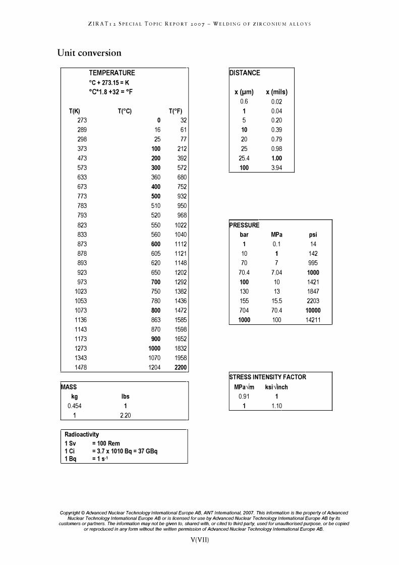
Unit conversion
TEMPERATURE DISTANCE
°C + 273.15 = K
°C*1.S +32 = of x (!.1m) x (mils) 0.6 0.02
T(K) T(°C) T(OF) 0.04
273 0 32 5 0.20
289 16 61 10 0.39
298 25 77 20 0.79
373 100 212 25 0.98
473 200 392 25.4 1.00
573 300 572 100 3.94
633 360 680
673 400 752
773 500 932
783 510 950
793 520 968
823 550 1022 PRESSURE
833 560 1040 bar MPa psi
873 600 1112 0.1 14
878 605 1121 10 142
893 620 1148 70 7 995
923 650 1202 70.4 7.04 1000
973 700 1292 100 10 1421
1023 750 1382 130 13 1847
1053 780 1436 155 15.5 2203
1073 SOO 1472 704 70.4 10000
1136 863 1585 1000 100 14211
1143 870 1598
1173 900 1652
1273 1000 1832
1343 1070 1958
1478 1204 2200
STRESS INTENSITY FACTOR
MASS MPa-vm ksi-vinch
kg Ibs 0.91 1
0.454 1 1.10
2.20
Radioactivity 1 Sv = 100 Rem 1 Ci = 3.7 x 10¹⁰ 8q = 37 G8q 18q = 1 S·1
Copyright © Advanced Nuclear Technology International Europe AB, ANT International, 2007. This information is the property of Advanced
Nuclear Technology International Europe AB or is licensed for use by Advanced Nuclear Technology International Europe AB by its customers or partners. The information may not be given to, shared with, or cited to third party, used for unauthorised purpose, or be copied
or reproduced in any form without the written permission of Advanced Nuclear Technology International Europe AB.
V(VII)
ZIRATr 2 SPECIAL TOPIC REPORT 2007 - WELDING OF ZIRCONIUM ALLOYS
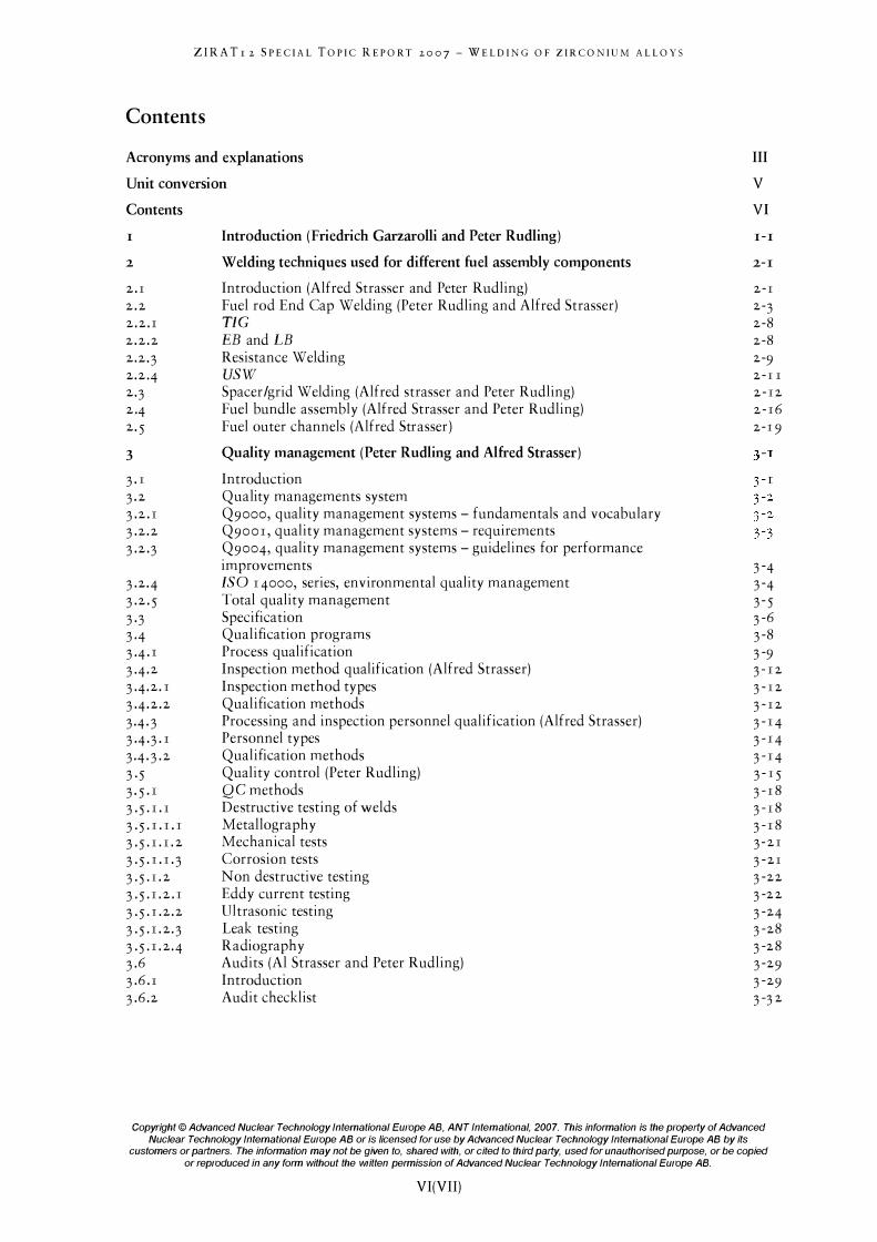
Contents
Acronyms and explanations
Unit conversion
Contents
I
2
2 . 1 2 . 2 2 . 2 . 1 2 . 2 . 2 2 .2·3 2 .2·4 2·3 2·4 2· 5
3 3 . 1 3 . 2 3 .2 . 1 3 .2 .2 3 .2 .3
3 .2 .4 3 .2 . 5 3·3 3·4 3 .4 . 1 3 .4 .2 3 .4 .2 . 1 3 .4 .2 .2 3+3 3+3 . 1 3+3 . 2 3 · 5 3 . 5 . 1 3 · 5· 1 . 1 3 · 5· 1 . 1 . 1 3 · 5· 1 . 1 . 2 3 · 5· 1 . 1 .3 3 · 5· 1 . 2 3 · 5· 1 . 2 . 1 3 · 5· 1 . 2 . 2 3 · 5· 1 . 2·3 3 · 5· 1 . 2·4 3 .6 3 .6 . 1 3 .6 .2
Introduction (Friedrich Garzarolli and Peter Rudling)
Welding techniques used for different fuel assembly components
Introduction (Alfred Strasser and Peter Rudling) Fuel rod End Cap Welding (Peter Rudling and Alfred Strasser) TIC EB and LB Resistance Welding USW Spacer/grid Welding (Alfred strasser and Peter Rudling) Fuel bundle assembly (Alfred Strasser and Peter Rudling) Fuel outer channels (Alfred Strasser )
Quality management (Peter Rudling and Alfred Strasser)
Introduction Quality managements system Q9000, quality management systems - fundamentals and vocabulary Q9001 , quality management systems - requirements Q9004, quality management systems - guidelines for performance improvements ISO 1 4000, series, environmental quality management Total quality management Specifica tion Qualification programs Process qualification Inspection method qualification (Alfred Strasser) Inspection method types Qualification methods Processing and inspection personnel qualification (Alfred Strasser) Personnel types Qualification methods Quality control (Peter Rudling) QC methods Destructive testing of welds Metallogra phy Mechanical tests Corrosion tests N on destructive testing Eddy current testing Ultrasonic testing Leak testing Radiography Audits (AI Strasser and Peter Rudling) Introduction Audit checklist
III
V
VI
I-I
2-1
2-1 2-3 2-8 2-8 2-9 2 - 1 I 2 - 12 2 - 16 2-19
3 -4 3 -4 3 - 5 3 -6 3 -8 3 -9 3 - 1 2 3 - 1 2 3 - 1 2 3 - 1 4 3 - 1 4 3 - 1 4 3 - 1 5 3 - 18 3 - 18 3 - 18 3 - 2 1 3 -21 3 -22 3 -2 2 3 -24 3 -28 3 -28 3 -29 3 -29 3 -3 2
Copyright © Advanced Nuclear Technology International Europe AB, ANT International, 2007. This information is the property of Advanced
Nuclear Technology International Europe AB or is licensed for use by Advanced Nuclear Technology International Europe AB by its customers or partners. The information may not be given to, shared with, or cited to third party, used for unauthorised purpose, or be copied
or reproduced in any form without the written permission of Advanced Nuclear Technology International Europe AB.
VI(VII)
4
4 . 1 4· 1 . 1 4· 1 .2 4· 1 .3
ZIRATr 2 SPECIAL TOPIC REPORT 2007 - WELDING OF ZIRCONIUM ALLOYS
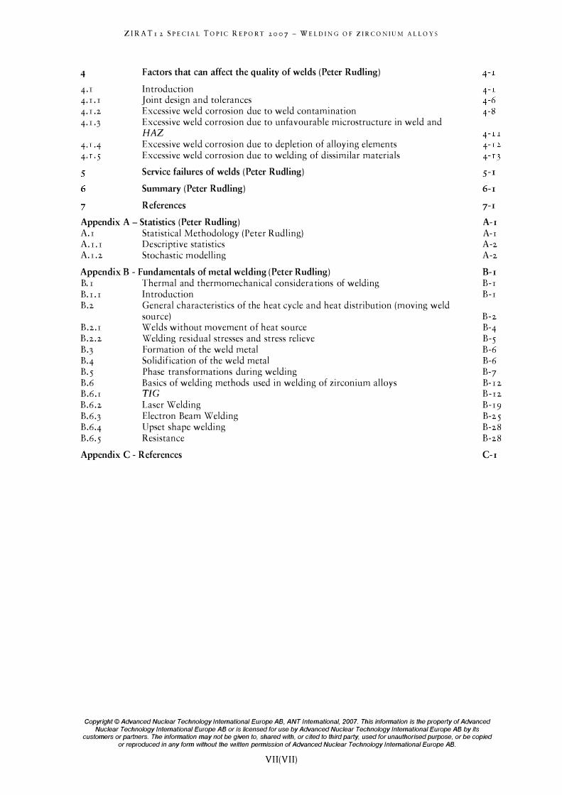
Factors that can affect the quality of welds (Peter Rudling)
Introduction J oint design and tolerances Excessive weld corrosion due to weld contamination Excessive weld corrosion due to unfavourable microstructure in weld and HAZ Excessive weld corrosion due to depletion of alloying elements Excessive weld corrosion due to welding of dissimilar materials
Service failures of welds (Peter Rudling)
Summary (Peter Rudling)
References
Appendix A - Statistics (Peter Rudling) A.I Statistical Methodology (Peter Rudling) A.I.I Descriptive statistics A.I. 2 Stochastic modelling
Appendix B - Fundamentals of metal welding (Peter Rudling) B. I Thermal and thermomechanical consider a tions of welding B.I.I Introduction B .2 General characteristics of the heat cycle and heat distribution (moving weld
B .2 . 1 B .2 .2 B·3 B·4 B· 5 B .6 B .6 . 1 B .6 .2 B. 6·3 B .6·4 B .6· 5
source) Welds without movement of heat source Welding residual stresses and stress relieve Formation of the weld metal Solidification of the weld metal Phase transformations during welding Basics of welding methods used in welding of zirconium alloys TIC Laser Welding Electron Beam Welding Upset shape welding Resistance
Appendix C - References
5-1
6-1
7-1
A-I A-I A-2 A-2
B-1 B-1 B-1
B-2 B-4 B-5 B-6 B-6 B-7 B- 1 2 B - 12 B-19 B-2 5 B-28 B-28
C-I
Copyright © Advanced Nuclear Technology International Europe AB, ANT International, 2007. This information is the property of Advanced
Nuclear Technology International Europe AB or is licensed for use by Advanced Nuclear Technology International Europe AB by its customers or partners. The information may not be given to, shared with, or cited to third party, used for unauthorised purpose, or be copied
or reproduced in any form without the written permission of Advanced Nuclear Technology International Europe AB.
VII(VII)

I
ZIRATr 2 SPECIAL TOPIC REPORT 2007 - WELDING OF ZIRCONIUM ALLOYS
Introduction (Friedrich Garzarolli and Peter Rudling)
The welding of Zirconium Alloy components is one of the most critical manufacturing processes of Nuclear Reactor fuel. Small amounts of contamination resulting from inadequate cleanliness or from poor atmospheric control during welding may lead to diminished corrosion resistance of the weld and in severe cases to weld failure. Other weld defects such as piping, pore formation or insufficient weld penetration may also result in costly fuel failures.
This Special Topic Report (STR) describes the different welding processes used for the various fuel assembly components. A comprehensive discussion of welding Quality Management is included. The fundamental aspects of the welding process, focussing on Tungsten Inert Gas (TIC), Electron Beam, Laser and Resistance welding as well as solid state bonding are made an integral part of the report.
This Topical Report has been specifically prepared for the use of utility personnel, engineers and auditors that are involved in the procurement of nuclear fuel and which may have limited indept knowledge of welding processes and procedures. A discussion of the fundamentals of Zirconium Alloy Welding Metallurgy is for the benefit of metallurgists and welding engineers as well as for others that wish to obtain greater insight into this topic. However, before we start to look into the welding technology in the next sections it is instructive to look back in history to find out which different Zr-alloys were developed, why and, which Zr alloys are being used today. The latter alloys are the ones that should be weldable.
The initial fuel rods of early Boiling Water Reactor (BWRs) and Pressurised Water Reactor (PWRs) applied very thin Stainless Steel (SS) clad. This material was selected due to its rather high strength and excellent corrosion resistance in high temperature water. The behavior of these SS cladding was quite good in PWRs but manifested severe longitudinal intergranular cracking in BWRs after burnups in excess of 6 MWd/kgU. Because of these defects and economic considerations, ZircaloY-2 and ZircaloY-4 ( see Table I - I ) , Zr-based alloys with very low neutron absorption cross section developed at the Bettis Atomic Power Laboratory, e.g., Kass, 1962 were used later for PWRs and BWRs.
Copyright © Advanced Nuclear Technology International Europe AB, ANT International, 2007. This information i s the property o f Advanced
Nuclear Technology International Europe AB or is licensed for use by Advanced Nuclear Technology International Europe AB by its customers or partners. The information may not be given to, shared with, or cited to third party, used for unauthorised purpose, or be copied
or reproduced in any form without the written permission of Advanced Nuclear Technology International Europe AB.
1 - 1 ( 1 - 5 )
ZIRA Tr 2 SPECIAL TOPIC REPORT 2007 - WELDING OF ZIRCONIUM ALLOYS
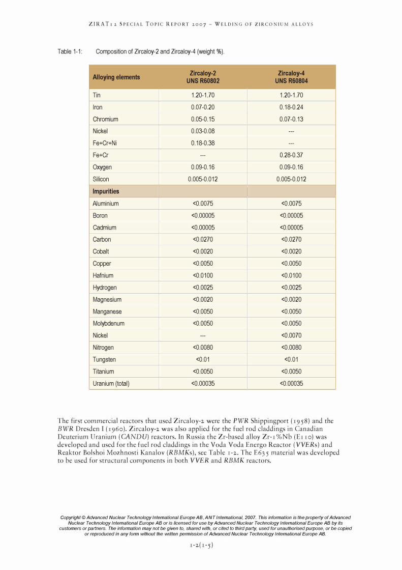
Table 1-1: Composition of Zircaloy-2 and Zircaloy-4 (weight %).
.....--Alloying elements
Zircaloy-2 Zircaloy-4 UNS R60802 UNS R60804
Tin I 1.20-1.70 1.20-1.70 -Iron 0.07-0.20 0.18-0.24 -Chromium 0.05-0.15 0.07-0.13 -Nickel 0.03-0.08 --- -Fe+Cr+Ni 0.18-0.38 --- -Fe+Cr --- 0.28-0.37 -Oxygen 0.09-0.16 0.09-0.16 -Silicon 0.005-0.012 0.005-0.012
-----. Impurities
Aluminium <0.0075 <0.0075 -Boron <0.00005 <0.00005 -Cadmium <0.00005 <0.00005 -Carbon <0.0270 <0.0270 -Cobalt <0.0020 <0.0020 -Copper <0.0050 <0.0050 -Hafnium <0.0100 <0.0100 -Hydrogen <0.0025 <0.0025 -Magnesium <0.0020 <0.0020 -Manganese <0.0050 <0.0050 -Molybdenum <0.0050 <0.0050 -Nickel --- <0.0070 -Nitrogen <0.0080 <0.0080 -Tungsten <0.01 <0.01 -Titanium <0.0050 <0.0050 -Uranium (total) <0.00035 <0.00035
The first commercial reactors that used ZircaloY-2 were the PWR Shippingport ( r9 58) and the BWR Dresden I ( r960) . ZircaloY-2 was also applied for the fuel rod claddings in Canadian Deuterium Uranium (CANDU) reactors. In Russia the Zr-based alloy Zr- r %Nb (Er ro) was developed and used for the fuel rod claddings in the Voda Voda Energo Reactor (VVERs) and Reaktor Bolshoi Mozhnosti Kanalov (RBMKs), see Table r -2 . The E63 5 material was developed to be used for structural components in both VVER and RBMK reactors.
Copyright © Advanced Nuclear Technology International Europe AB. ANT Intemational. 2007. This information is the property of Advanced
Nuclear Technology International Europe AB or is licensed for use by Advanced Nuclear Technology International Europe AB by its customers or partners. The information may not be given to. shared with. or cited to third party. used for unauthorised purpose. or be copied
or reproduced in any form without the written permission of Advanced Nuclear Technology International Europe AB.
r-2 ( r - 5 )
ZIRATr 2 SPECIAL TOPIC REPORT 2007 - WELDING OF ZIRCONIUM ALLOYS
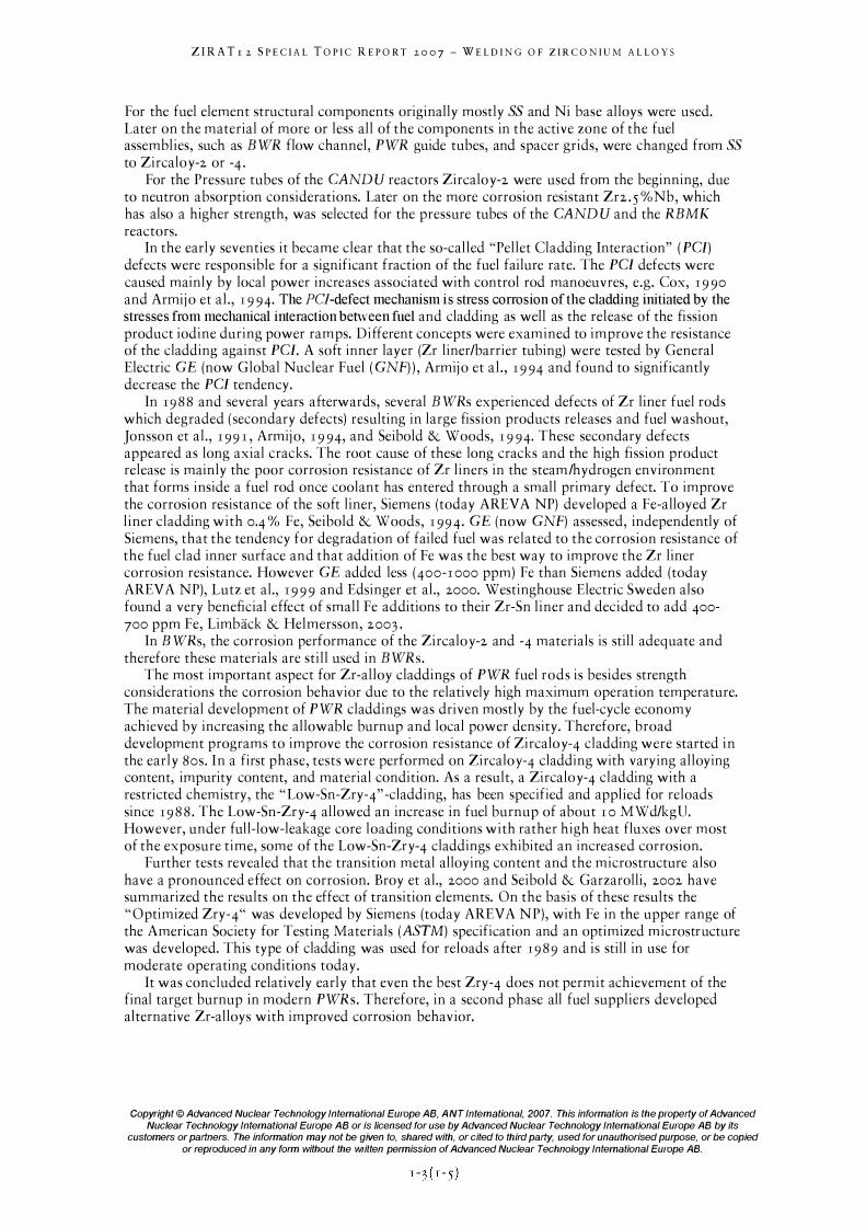
For the fuel element structural components originally mostly SS and Ni base alloys were used. Later on the material of more or less all of the components in the active zone of the fuel assemblies, such as BWR flow channel, PWR guide tubes, and spacer grids, were changed from SS to ZircaloY-2 or -4 .
For the Pressure tubes of the CANDU reactors ZircaloY-2 were used from the beginning, due to neutron absorption considerations. Later on the more corrosion resistant Zf2 . 5 %Nb, which has also a higher strength, was selected for the pressure tubes of the CAND U and the RBMK reactors.
In the early seventies it became clear that the so-called "Pellet Cladding Interaction" (PCI) defects were responsible for a significant fraction of the fuel failure rate. The PCI defects were caused mainly by local power increases associated with control rod manoeuvres, e.g. Cox, 1990 and Armij o et aI., 1994. The pel-defect mechanism is stress corrosion of the cladding initiated by the stresses from mechanical interaction between fuel and cladding as well as the release of the fission product iodine during power ramps. Different concepts were examined to improve the resistance of the cladding against PCI. A soft inner layer (Zr liner/barrier tubing) were tested by General Electric GE (now Global Nuclear Fuel (GNF) ) , Armij o et aI. , 1994 and found to significantly decrease the PCI tendency.
In 1988 and several years afterwards, several BWRs experienced defects of Zr liner fuel rods which degraded ( secondary defects) resulting in large fission products releases and fuel washout, Jonsson et aI., 199 1 , Armij o, 1994, and Seibold & Woods, 1994. These secondary defects appeared as long axial cracks. The root cause of these long cracks and the high fission product release is mainly the poor corrosion resistance of Zr liners in the steam/hydrogen environment that forms inside a fuel rod once coolant has entered through a small primary defect. To improve the corrosion resistance of the soft liner, Siemens (today AREVA NP) developed a Fe-alloyed Zr liner cladding with 0.4 % Fe, Seibold & Woods, 1994. GE (now GNF) assessed, independently of Siemens, that the tendency for degradation of failed fuel was related to the corrosion resistance of the fuel clad inner surface and that addition of Fe was the best way to improve the Zr liner corrosion resistance. However GE added less (400-1 000 ppm) Fe than Siemens added (today AREV A NP), Lutz et aI., 1999 and Edsinger et aI., 2000. Westinghouse Electric Sweden also found a very beneficial effect of small Fe additions to their Zr-Sn liner and decided to add 400-700 ppm Fe, Limback & Helmersson, 2003 .
In BWRs, the corrosion performance of the ZircaloY-2 and -4 materials is still adequate and therefore these materials are still used in BWRs.
The most important aspect for Zr-alloy claddings of PWR fuel rods is besides strength considerations the corrosion behavior due to the relatively high maximum operation temperature. The material development of PWR claddings was driven mostly by the fuel-cycle economy achieved by increasing the allowable burnup and local power density. Therefore, broad development programs to improve the corrosion resistance of ZircaloY-4 cladding were started in the early 80S . In a first phase, tests were performed on ZircaloY-4 cladding with varying alloying content, impurity content, and material condition. As a result, a ZircaloY-4 cladding with a restricted chemistry, the "Low-Sn-ZrY-4" -cladding, has been specified and applied for reloads since 1988. The Low-Sn-ZrY-4 allowed an increase in fuel burnup of about 1 0 MWd/kgU. However, under full-low-leakage core loading conditions with rather high heat fluxes over most of the exposure time, some of the Low-Sn-ZrY-4 claddings exhibited an increased corrosion.
Further tests revealed that the transition metal alloying content and the microstructure also have a pronounced effect on corrosion. Broy et aI., 2000 and Seibold & Garzarolli, 2002 have summarized the results on the effect of transition elements. On the basis of these results the " Optimized Zry-4" was developed by Siemens (today AREV A NP), with Fe in the upper range of the American Society for Testing Materials (ASTM) specification and an optimized microstructure was developed. This type of cladding was used for reloads after 1989 and is still in use for moderate operating conditions today.
It was concluded relatively early that even the best Zry-4 does not permit achievement of the final target burnup in modern PWRs. Therefore, in a second phase all fuel suppliers developed alternative Zr-alloys with improved corrosion behavior.
Copyright © Advanced Nuclear Technology International Europe AB, ANT International, 2007. This information is the property of Advanced
Nuclear Technology International Europe AB or is licensed for use by Advanced Nuclear Technology International Europe AB by its customers or partners. The information may not be given to, shared with, or cited to third party, used for unauthorised purpose, or be copied
or reproduced in any form without the written permission of Advanced Nuclear Technology International Europe AB.
ZIRATr 2 SPECIAL TOPIC REPORT 2007 - WELDING OF ZIRCONIUM ALLOYS
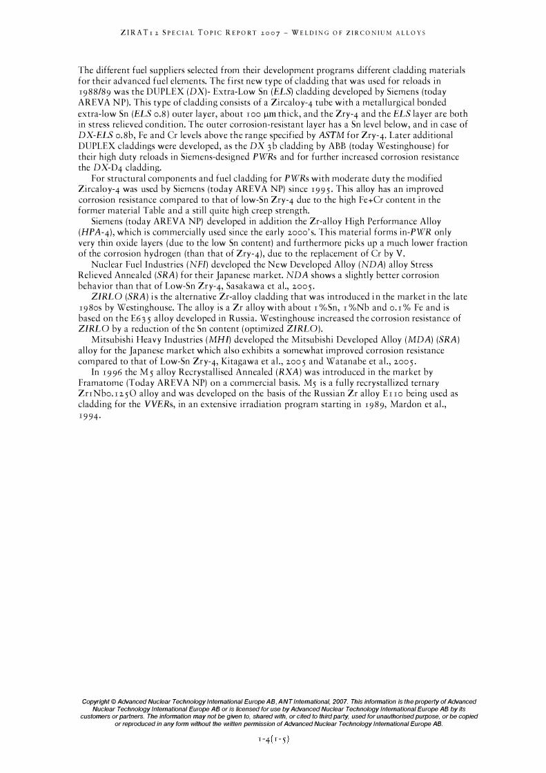
The different fuel suppliers selected from their development programs different cladding materials for their advanced fuel elements. The first new type of cladding that was used for reloads in 1988/89 was the DUPLEX (DX)- Extra-Low Sn (ELS) cladding developed by Siemens (today AREV A NP). This type of cladding consists of a ZircaloY-4 tube with a metallurgical bonded extra-low Sn (ELS 0.8 ) outer layer, about 1 00 flill thick, and the Zry-4 and the ELS layer are both in stress relieved condition. The outer corrosion-resistant layer has a Sn level below, and in case of DX-ELS 0.8b, Fe and Cr levels above the range specified by ASTM for ZrY-4. Later additional DUPLEX claddings were developed, as the DX 3 b cladding by ABB (today Westinghouse ) for their high duty reloads in Siemens-designed PWRs and for further increased corrosion resistance the DX-D4 cladding.
For structural components and fuel cladding for PWRs with moderate duty the modified ZircaloY-4 was used by Siemens (today AREVA NP) since 199 5 . This alloy has an improved corrosion resistance compared to that of low-Sn Zry-4 due to the high Fe+Cr content in the former material Table and a still quite high creep strength.
Siemens (today AREVA NP) developed in addition the Zr-alloy High Performance Alloy (HPA-4), which is commercially used since the early 2000'S. This material forms in-PWR only very thin oxide layers (due to the low Sn content) and furthermore picks up a much lower fraction of the corrosion hydrogen (than that of ZrY-4), due to the replacement of Cr by V.
Nuclear Fuel Industries (NFl) developed the New Developed Alloy (NDA) alloy Stress Relieved Annealed (SRA) for their Japanese market. NDA shows a slightly better corrosion behavior than that of Low-Sn ZrY-4, Sa sakawa et aI., 200 5 .
ZIRLO (SRA) i s the alternative Zr-alloy cladding that was introduced i n the market i n the late 1980s by Westinghouse. The alloy is a Zr alloy with a bout 1 % Sn, 1 %Nb and 0. 1 % Fe and is based on the E63 5 alloy developed in Russia. Westinghouse increased the corrosion resistance of ZIRLO by a reduction of the Sn content (optimized ZIRLO).
Mitsubishi Heavy Industries (MHI) developed the Mitsubishi Developed Alloy (MDA) (SRA) alloy for the Japanese market which also exhibits a somewhat improved corrosion resistance compared to that of Low-Sn ZrY-4, Kitagawa et aI., 200 5 and Watanabe et aI., 200 5 .
In 1996 the M 5 alloy Recrystallised Annealed (RXA ) was introduced in the market by Framatome (Today AREVA NP) on a commercial basis. M5 is a fully recrystallized ternary ZrrNbo.I2 50 alloy and was developed on the basis of the Russian Zr alloy EII0 being used as cladding for the VVERs, in an extensive irradiation program starting in 1989, Mardon et aI., 1994·
Copyright © Advanced Nuclear Technology International Europe AB, ANT International, 2007. This information is the property of Advanced
Nuclear Technology International Europe AB or is licensed for use by Advanced Nuclear Technology International Europe AB by its customers or partners. The information may not be given to, shared with, or cited to third party, used for unauthorised purpose, or be copied
or reproduced in any form without the written permission of Advanced Nuclear Technology International Europe AB.
ZIRA Tr 2 SPECIAL TOPIC REPORT 2007 - WELDING OF ZIRCONIUM ALLOYS
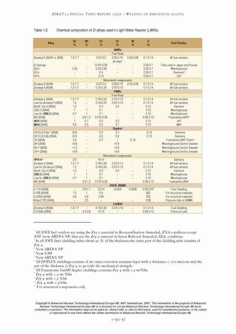
Table 1-2: Chemical composition of Zr alloys used in Light Water Reactor (LWRs).
� �
Alloy Sn Nb Fe Cr Ni 0 Fuel Vendor. % % % % % % r---
BWRs -
- -Fuel Rods
Zircaloy-2 (RXN or SRA) 1.2-1.7 0.07-0.2 0.05-0.15 003-0.0S 0.1-0.14 All fuel vendors Zr-liner2
Zr Sponge 0.015-0.06 0.05-0.1 Only used in Japan and Russia ZrSn 0.25 0.03-0.06 0.05-0.1 Westinghouse ZrFe 0.4 0.05-0.1 Siemens3 ZrFe 0.10 0.05-0.1 GE4 -
-- - Structural c�onents - -Zircaloy-2 (RXA) 1.2-1.7 0.07-0.2 0.05-0.15 003-0.0S 0.1-0.14 All fuel vendors Zircalo)'-4 (RXA) 1.2-1.7 0.1S-0.24 007-0.13 0.1-0.14 All fuel vendors
PWRs Fuel Rods
Zircaloy-4 (SRA) 1.2-1.7 0.1S-0.24 007-0.13 0.1-0.14 All fuel vendors Low Sn Zircaloy-4 (SRA) 1.3 0.1S-0.24 007-0.13 0.1-0.14 All fuel vendors Modi! Zry-4 (SRA) 1.3 03 0.2 0.12 Siemens ZIRLO (SRA) 1 1 0.1 0.12 Westinghouse Low Sn ZIRLO (SRA) 0.7 1 0.1 0.12 Westinghouse M5 (RXA) 0.S-1.2 0.015-0.06 0.09-0.12 Framatome ANp5 NDA(SRA) 1 0.1 03 0.2 0.12 NFl MDA(SRA) O.S 0.5 0.2 0.1 0.12 MHI
OXELS 0 .Sa 7 (SRA)
Duplex6 ---/O.S 0.2 0.1 0.12 Siemens
OX ELS O.Sb (SRA) /O.S 03 0.2 0.12 Siemens D4 (SRA) 0.5 0.7 0.12 Framatome ANP GmbH 3bB (SRA) <O.S <0.6 Westinghouse Electric Sweden
3b+9 (SRA) <10 <0.6 Westinghouse Electric Sweden
D410 (SRA) <O.S <0.6 Westinghouse Electric Sweden
Structural comronents
HPA-411 0.5 Fe+V Siemens
Zircaloy-4 (SRA) 1.2-1.7 0.1S-0.24 007-0.13 0.1-0.14 All fuel vendors Low Sn Zircaloy-4 (SRA) 1.3 0.1S-0.24 007-0.13 0.1-0.14 All fuel vendors Modi! Zry-4 (SRA) 1.3 03 0.2 0.12 Siemens ZIRLO(SRA) 1 1 0.1 0.12 Westinghouse Low Sn ZIRLO (SRA) 0.7 1 0.1 0.12 Westinghouse M5 (RXA) 0.S-1.2 0.015-0.06 0.09-0.12 Framatome ANP
WER,RBMK -' E-110 (RXA) 0.9-1.1 0.014 <0.003 0.0035 0.05-0.07 Fuel Cladding E-635 (RXA) 1.3 1 0.4 900 For structural materials E-635M (RXA) O.S O.S 035 700 For structural materials Alloy E12�R.el 2.5 0.06 Pressure tube in RBMK
CANDU .....,
-' Zircaloy-4 (RXA) 1.2-1.7 0.1S-0.24 007-0.13 0.1-0.14 Fuel Cladding Zr2.5Nb (SRA) 2.4-2.S <0.15 0.09-0.13 Pressure tube
, All BWR fuel vendors are using the ZrY-2 material in Recrystallisation Annealed, RXA condition except ANF (now AREV A NP) that use the Zry-2 material in Stress Relieved Annealed, SRA, condition. , In all BWR liner cladding tubes about 90 % of the thickness-the outer part of the cladding tube consists of Zry-2. ) Now AREVA NP 4NowGNF 5 Now AREVA NP 6 All DUPLEX claddings consists of an outer corrosion resistant layer with a thickness < 100 microns and the rest of the thickness is Zry-4 to provide the mechanical strength. 7 All Framatome GmbH duplex claddings contains Zry-4 with 1.5 wt%Sn 8 Zry-4 with 1.3 wt %Sn 9 Zry-4 with 1.5 %Sn w Zry-4 with 1. 5 %Sn U For structural components only
Copyright © Advanced Nuclear Technology International Europe AB, ANT Intemational, 2007. This information is the property of Advanced
Nuclear Technology International Europe AB or is licensed for use by Advanced Nuclear Technology International Europe AB by its customers or partners. The information may not be given to, shared with, or cited to third party, used for unauthorised purpose, or be copied
or reproduced in any form without the written permission of Advanced Nuclear Technology International Europe AB.
1 - 5 ( 1 - 5 )
2
2.1
ZIRA Tr 2 SPECIAL TOPIC REPORT 2007 - WELDING OF ZIRCONIUM ALLOYS
Welding techniques used for different fuel assembly components
Introduction (Alfred Strasser and Peter Rudling) Welding is a fabrication process that j oins materials, usually metals or thermoplastics, by causing coalescence". This is often done by melting the workpieces and adding a filler material to form a pool of molten material (the weld puddle) that cools to become a strong joint, with pressure sometimes used in conj unction with heat, or by itself, to produce the weld.
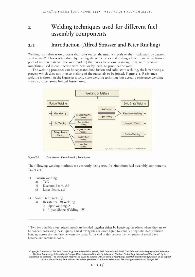
The welding processes can be separated into fusion and solid state welding, the latter being a process which does not involve melting of the materials to be joined, Figure 2-1. Resistance welding is shown in the figure as a solid state welding technique but actually resistance welding may also cause some limited fusion zone.
Welding of Metals
Fusion Welding Solid State Welding
Resistance Welding
Ultrasonic Welding
Friction Welding
Figure - Redrawn and modihed Irom OIiglnal b,' A r\I ,l I NTERNATlONAL 2007
Figure 2-1: Overview of different welding techniques.
The following welding methods are currently being used for zirconium fuel assembly components, Table 2-r:
r ) Fusion welding a) TIC b) Electron Beam, EB c) Laser Beam, LB
2) Solid State Welding a) Resistance (R) welding
i) Spot welding, S ii) Upset Shape Welding, US
n Two (or possibly more) pieces metals are bonded together either by liquefying the places where they are to be bonded, coalescing these liquids, and allowing the coalesced liquid to solidify or by solid state diffusion bonding across the interface between the parts. At the end of this process the two pieces of metal have become one continous solid.
Copyright © Advanced Nuclear Technology International Europe AB, ANT Intemational, 2007. This information is the property of Advanced
Nuclear Technology International Europe AB or is licensed for use by Advanced Nuclear Technology International Europe AB by its customers or partners. The information may not be given to, shared with, or cited to third party, used for unauthorised purpose, or be copied
or reproduced in any form without the written permission of Advanced Nuclear Technology International Europe AB.
ZIRA Tr 2 SPECIAL TOPIC REPORT 2007 - WELDING OF ZIRCONIUM ALLOYS
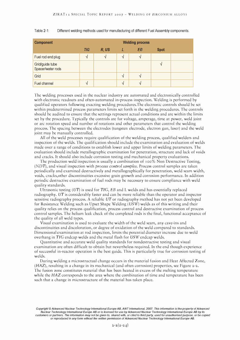
Table 2-1: Different welding methods used for manufacturing of different Fuel Assembly components.
Component Welding process
TlG R,US L EB Spot
Fuel rod end plug '-l '-l '-l '-l
Grid/guide tube '-l Spacer/water rods
Grid '-l '-l
Fuel channel '-l '-l '-l
The welding processes used in the nuclear industry are automated and electronically controlled with electronic readouts and often-automated in-process inspection. Welding is performed by qualified operators following exacting welding procedures. The electronic controls should be set within predetermined process parameters limits set forth in the welding procedures. The controls should be audited to ensure that the settings represent actual conditions and are within the limits set by the procedure. Typically the controls are for voltage, amperage, time at power, weld joint or arc rotation speed and number of rotations and other parameters that control the welding process. The spacing between the electrodes (tungsten electrode, electron gun, laser) and the weld joint may be manually controlled.
All of the weld processes require qualification of the welding process, qualified welders and inspection of the welds. The qualification should include the examination and evaluation of welds made over a range of conditions to establish lower and upper limits of welding parameters. The evaluation should include metallographic examination for penetration, structure and lack of voids and cracks. It should also include corrosion testing and mechanical property evaluations.
The production weld inspection is usually a combination of 1 00% Non Destructive Testing, (NDT) , and visual inspection with process control samples. Process control samples are taken periodically and examined destructively and metallographically for penetration, weld seam width, voids, cracks, other discontinuities excessive grain growth and corrosion performance. In addition periodic destructive examination of fuel rods may be necessary to ensure compliance with weld quality standards.
Ultrasonic testing (UT) is used for TIC, EB and L welds and has essentially replaced radiography. UT is considerably faster and can be more reliable than the operator and inspector sensitive radiography process. A reliable UT or radiography method has not yet been developed for Resistance Welding such as Upset Shape Welding (USW) welds as of this writing and their quality relies on the process qualification, process control and destructive examination of process control samples. The helium leak check of the completed rods is the final, functional acceptance of the quality of all weld types.
Visual examination is used to evaluate the width of the weld seam, any cave-ins and discontinuities and discoloration, or degree of oxidation of the weld compared to standards. Dimensional examination at rod inspection, limits the potential diameter increase due to weld overhang in TIC endcap welds and the metal flash for USW endcap welds.
Quantitative and accurate weld quality standards for nondestructive testing and visual examination are often difficult to obtain but nevertheless required. In the end though experience of successful in-reactor operation is the best guide. This is particularly true for corrosion testing of welds.
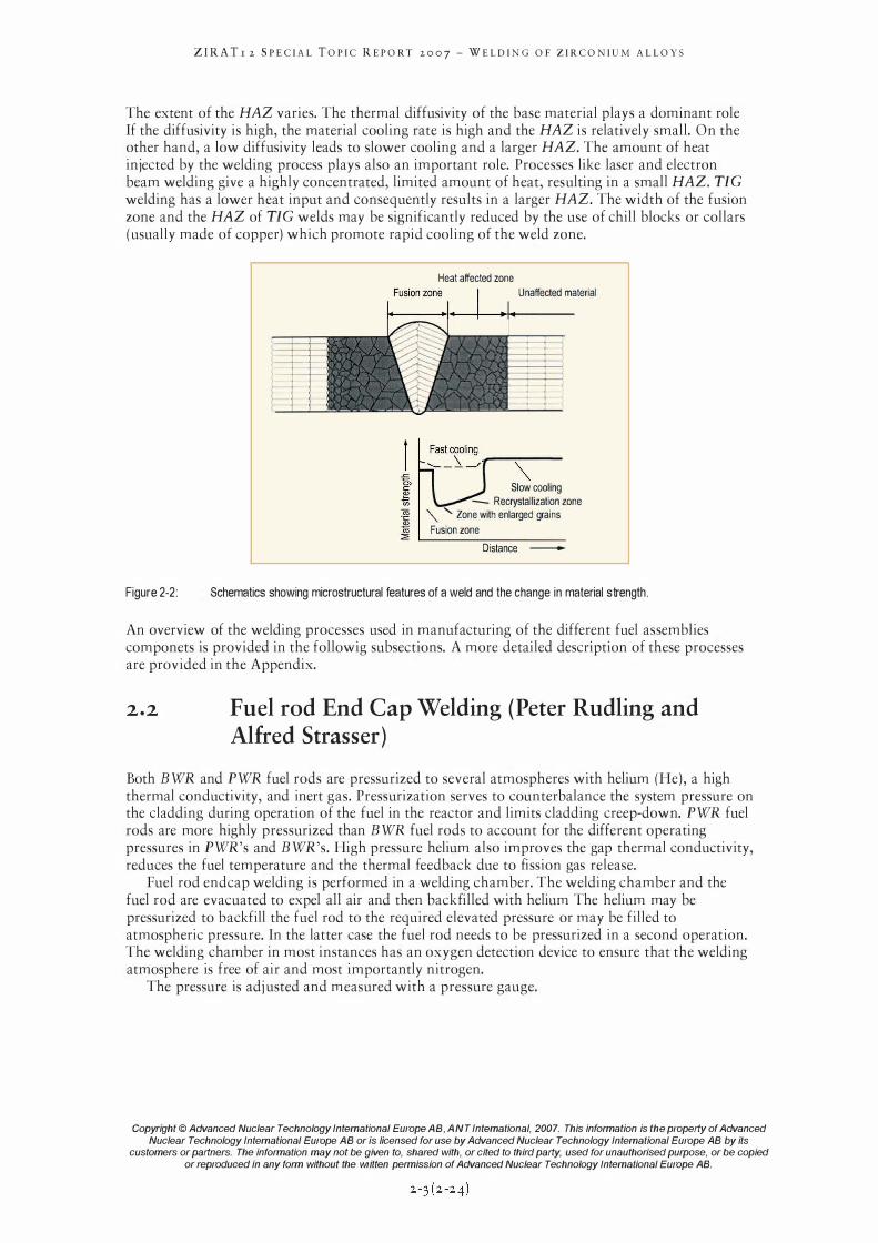
During welding a microstructual change occurs in the material fusion and Heat Affected Zone, (HAZ) , resulting in a change in its mechanical (and often corrosion) properties, see Figure 2-2. The fusion zone constitutes material that has been heated in excess of the melting temperature while the HAZ corresponds to the area where the combination of time and temperature has been such that a change in microstructure of the material has taken place.
Copyright © Advanced Nuclear Technology International Europe AB. ANT Intemational. 2007. This information is the property of Advanced
Nuclear Technology International Europe AB or is licensed for use by Advanced Nuclear Technology International Europe AB by its customers or partners. The information may not be given to. shared with. or cited to third party. used for unauthorised purpose. or be copied
or reproduced in any form without the written permission of Advanced Nuclear Technology International Europe AB.
ZIRA Tr 2 SPECIAL TOPIC REPORT 2007 - WELDING OF ZIRCONIUM ALLOYS
The extent of the HAZ varies. The thermal diffusivity of the base material plays a dominant role If the diffusivity is high, the material cooling rate is high and the HAZ is relatively small. On the other hand, a low diffusivity leads to slower cooling and a larger HAZ. The amount of heat injected by the welding process plays also an important role. Processes like laser and electron beam welding give a highly concentrated, limited amount of heat, resulting in a small HAZ. TIC welding has a lower heat input and consequently results in a larger HAZ. The width of the fusion zone and the HAZ of TIC welds may be significantly reduced by the use of chill blocks or collars (usually made of copper) which promote rapid cooling of the weld zone.
Figure 2-2:
Heat affected zone
Unaffected material
"" Slow cooling
- Recrystallization zone '" "Zone with enlarged grains
Fusion zone
Distance -
Schematics showing microstructural features of a weld and the change in material strength.
An overview of the welding processes used in manufacturing of the different fuel assemblies componets is provided in the followig subsections. A more detailed description of these processes are provided in the Appendix.
2.2 Fuel rod End Cap Welding (Peter Rudling and Alfred Strasser)
Both BWR and PWR fuel rods are pressurized to several atmospheres with helium (He), a high thermal conductivity, and inert gas. Pressurization serves to counterbalance the system pressure on the cladding during operation of the fuel in the reactor and limits cladding creep-down. PWR fuel rods are more highly pressurized than BWR fuel rods to account for the different operating pressures in PWR's and BWR's. High pressure helium also improves the gap thermal conductivity, reduces the fuel temperature and the thermal feedback due to fission gas release.
Fuel rod endcap welding is performed in a welding chamber. The welding chamber and the fuel rod are evacuated to expel all air and then backfilled with helium The helium may be pressurized to backfill the fuel rod to the required elevated pressure or may be filled to atmospheric pressure. In the latter case the fuel rod needs to be pressurized in a second operation. The welding chamber in most instances has an oxygen detection device to ensure that the welding atmosphere is free of air and most importantly nitrogen.
The pressure is adj usted and measured with a pressure gauge.
Copyright © Advanced Nuclear Technology International Europe AB, ANT Intemational, 2007. This information is the property of Advanced
Nuclear Technology International Europe AB or is licensed for use by Advanced Nuclear Technology International Europe AB by its customers or partners. The information may not be given to, shared with, or cited to third party, used for unauthorised purpose, or be copied
or reproduced in any form without the written permission of Advanced Nuclear Technology International Europe AB.
ZIRA Tr 2 SPECIAL TOPIC REPORT 2007 - WELDING OF ZIRCONIUM ALLOYS
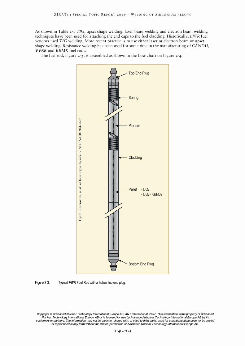
As shown in Table 2-1 TIC, upset shape welding, laser beam welding and electron beam welding techniques have been used for attaching the end caps to the fuel cladding. Historically, L WR fuel vendors used TIC welding, More recent practice is to use either laser or electron beam or upset shape welding. Resistance welding has been used for some time in the manufacturing of CANDU, VVER and RBMK fuel rods.
The fuel rod, Figure 2-3, is assembled as shown in the flow chart on Figure 2-4.
Top End Plug
Spring
Plenum
Cladding
Pellet - U02
- U02 - Gd203
Bottom End Plug
Figure 2-3: Typical PWR Fuel Rod with a hollow top end plug.
Copyright © Advanced Nuclear Technology International Europe AB, ANT Intemational, 2007. This information is the property of Advanced
Nuclear Technology International Europe AB or is licensed for use by Advanced Nuclear Technology International Europe AB by its customers or partners. The information may not be given to, shared with, or cited to third party, used for unauthorised purpose, or be copied
or reproduced in any form without the written permission of Advanced Nuclear Technology International Europe AB.
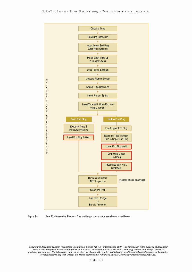
Figure 2-4:
ZIRA Tr 2 SPECIAL TOPIC REPORT 2007 - WELDING OF ZIRCONIUM ALLOYS
L Cladding Tube � Receiving Inspection �
Insert Lower End Plug Girth Weld Optional
Pellet Stack Make-up
& Length Check J Load Pellets & Weigh �
Measure Plenum Length � Decon Tube Open End
Insert Plenum Spring
Insert Tube With Open End Into
Weld Chamber
Pressurize With He Insert Upper End Plug
Insert End Plug & Weld Evacuate Tube Through
Hole In Upper End Plug
Lower End Plug Weld
Girth Weld Upper End Plug
Pressurize With He & Seal Weld
Dimensional Check NOT Inspection
Clean and Etch
Fuel Rod Storage or
Bundle Assembly
(He leak check, scanning)
Fuel Rod Assembly Process. The welding process steps are shown in red boxes.
Copyright © Advanced Nuclear Technology International Europe AB, ANT Intemational, 2007. This information is the property of Advanced
Nuclear Technology International Europe AB or is licensed for use by Advanced Nuclear Technology International Europe AB by its customers or partners. The information may not be given to, shared with, or cited to third party, used for unauthorised purpose, or be copied
or reproduced in any form without the written permission of Advanced Nuclear Technology International Europe AB.
ZIRA Tr 2 SPECIAL TOPIC REPORT 2007 - WELDING OF ZIRCONIUM ALLOYS
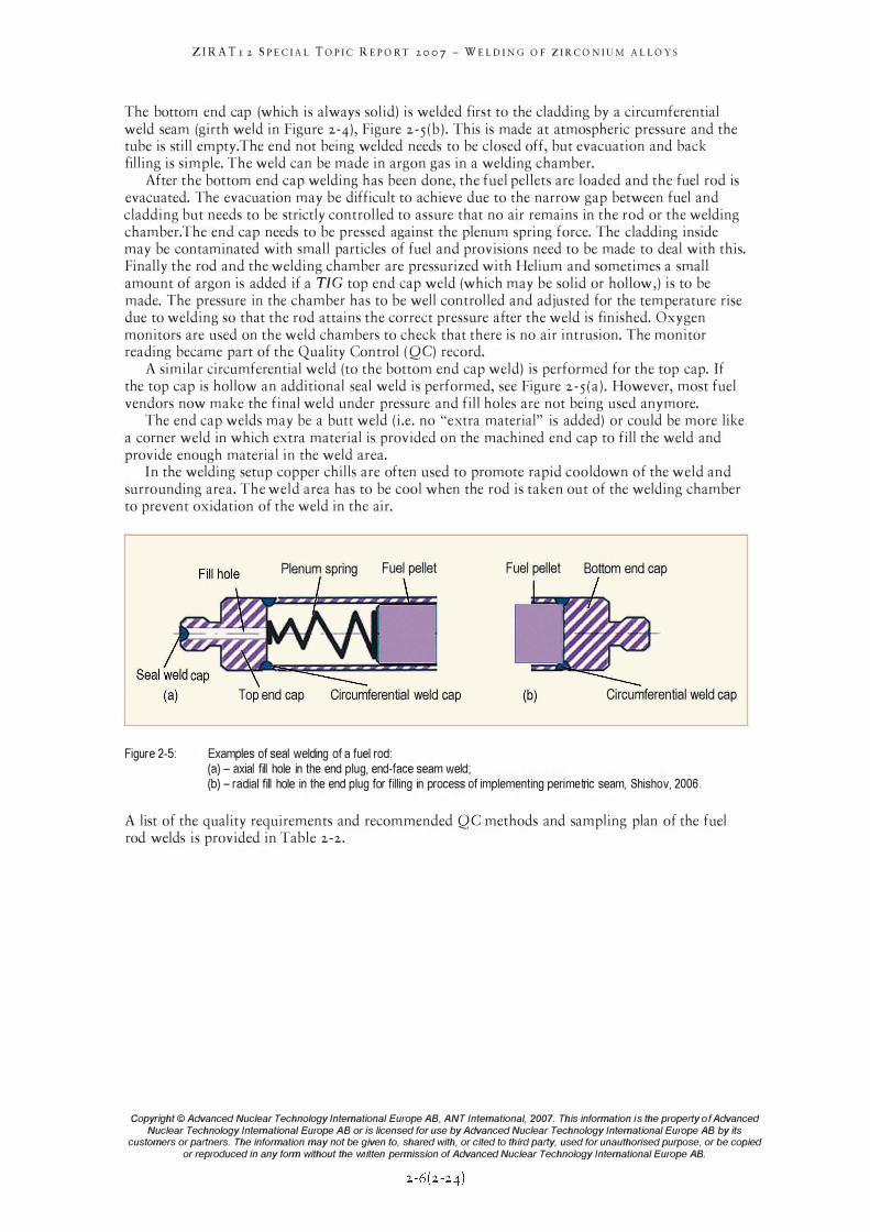
The bottom end cap (which is always solid) is welded first to the cladding by a circumferential weld seam (girth weld in Figure 2-4), Figure 2-5 (b ) . This is made at atmospheric pressure and the tube is still empty. The end not being welded needs to be closed off, but evacuation and back filling is simple. The weld can be made in argon gas in a welding chamber.
After the bottom end cap welding has been done, the fuel pellets are loaded and the fuel rod is evacuated. The evacuation may be difficult to achieve due to the narrow gap between fuel and cladding but needs to be strictly controlled to assure that no air remains in the rod or the welding chamber.The end cap needs to be pressed against the plenum spring force. The cladding inside may be contaminated with small particles of fuel and provisions need to be made to deal with this. Finally the rod and the welding chamber are pressurized with Helium and sometimes a small amount of argon is added if a TIC top end cap weld (which may be solid or hollow,) is to be made. The pressure in the chamber has to be well controlled and adjusted for the temperature rise due to welding so that the rod attains the correct pressure after the weld is finished. Oxygen monitors are used on the weld chambers to check that there is no air intrusion. The monitor reading became part of the Quality Control ( Q C) record.
A similar circumferential weld (to the bottom end cap weld) is performed for the top cap. If the top cap is hollow an additional seal weld is performed, see Figure 2 -5 (a ) . However, most fuel vendors now make the final weld under pressure and fill holes are not being used anymore.
The end cap welds may be a butt weld (i .e. no "extra material" is added) or could be more like a corner weld in which extra material is provided on the machined end cap to fill the weld and provide enough material in the weld area.
In the welding setup copper chills are often used to promote rapid cool down of the weld and surrounding area. The weld area has to be cool when the rod is taken out of the welding chamber to prevent oxidation of the weld in the air.
Plenum spring Fuel pellet Fuel pellet Boltom end cap
Top end cap Circumferential weld cap (b) Circumferential weld cap
Figure 2-5: Examples of seal welding of a fuel rod: (a) - axial fill hole in the end plug, end-face seam weld; (b) - radial fill hole in the end plug for filling in process of implementing peri metric seam, Shishov, 2006.
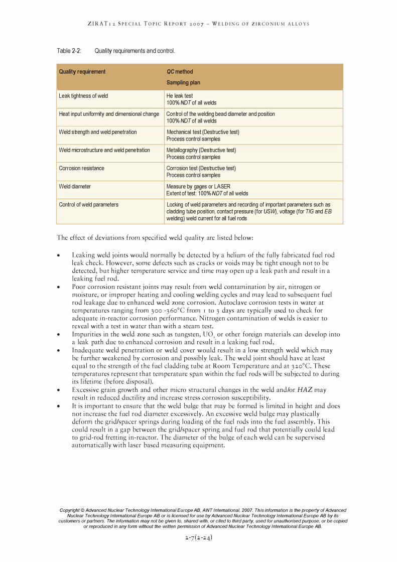
A list of the quality requirements and recommended Q C methods and sampling plan of the fuel rod welds is provided in Table 2-2.
Copyright © Advanced Nuclear Technology International Europe AB, ANT Intemational, 2007. This information i s the property o f Advanced
Nuclear Technology International Europe AB or is licensed for use by Advanced Nuclear Technology International Europe AB by its customers or partners. The information may not be given to, shared with, or cited to third party, used for unauthorised purpose, or be copied
or reproduced in any form without the written permission of Advanced Nuclear Technology International Europe AB.
ZIRA Tr 2 SPECIAL TOPIC REPORT 2007 - WELDING OF ZIRCONIUM ALLOYS
Table 2-2: Quality requirements and control.
Quality requirement QC method
Sampling plan
Leak tightness of weld He leak test 100% NOT of all welds
Heat input uniformity and dimensional change Control of the welding bead diameter and position 100% NOT of all welds
Weld strength and weld penetration Mechanical test (Destructive test) Process control samples
Weld microstructure and weld penetration Metallography (Destructive test) Process control samples
Corrosion resistance Corrosion test (Destructive test) Process control samples
Weld diameter Measure by gages or LASER Extent of test: 100% NOT of all welds
Control of weld parameters Locking of weld parameters and recording of important parameters such as cladding tube position, contact pressure (for USW), voltage (for TlG and fB welding) weld current for all fuel rods
The effect of deviations from specified weld quality are listed below:
• Leaking weld j oints would normally be detected by a helium of the fully fabricated fuel rod leak check. However, some defects such as cracks or voids may be tight enough not to be detected, but higher temperature service and time may open up a leak path and result in a leaking fuel rod.
• Poor corrosion resistant joints may result from weld contamination by air, nitrogen or moisture, or improper heating and cooling welding cycles and may lead to subsequent fuel rod leakage due to enhanced weld zone corrosion. Autoclave corrosion tests in water at temperatures ranging from 3 00 -3 60°C from I to 3 days are typically used to check for adequate in-reactor corrosion performance. Nitrogen contamination of welds is easier to reveal with a test in water than with a steam test.
• Impurities in the weld zone such as tungsten, U02 or other foreign materials can develop into a leak path due to enhanced corrosion and result in a leaking fuel rod,
• Inadequate weld penetration or weld cover would result in a low strength weld which may be further weakened by corrosion and possibly leak. The weld j oint should have at least equal to the strength of the fuel cladding tube at Room Temperature and at 3 20°C. These temperatures represent that temperature span within the fuel rods will be subjected to during its lifetime (before disposal).
• Excessive grain growth and other micro structural changes in the weld and/or HAZ may result in reduced ductility and increase stress corrosion susceptibility.
• It is important to ensure that the weld bulge that may be formed is limited in height and does not increase the fuel rod diameter excessively. An excessive weld bulge may plastically deform the grid/spacer springs during loading of the fuel rods into the fuel assembly. This could result in a gap between the grid/spacer spring and fuel rod that potentially could lead to grid-rod fretting in-reactor. The diameter of the bulge of each weld can be supervised automatically with laser based measuring equipment.
Copyright © Advanced Nuclear Technology International Europe AB, ANT Intemational, 2007. This information is the property of Advanced
Nuclear Technology International Europe AB or is licensed for use by Advanced Nuclear Technology International Europe AB by its customers or partners. The information may not be given to, shared with, or cited to third party, used for unauthorised purpose, or be copied
or reproduced in any form without the written permission of Advanced Nuclear Technology International Europe AB.
ZIRATr 2 SPECIAL TOPIC REPORT 2007 - WELDING OF ZIRCONIUM ALLOYS
2.2 . 1 TIG
17Gwelding fuses the weld joint by an electric arc generated between the tip of a tungsten electrode and the weld j oint. The necessary heat for welding is produced by an electric arc, between the Tungsten electrode and the metallic workpiece. The tungsten electrode which is not consumed during welding is usually alloyed with approximately 2 % rare earth metals to improve the TIC electrode electron emission. A direct current, with the tungsten electrode held at a negative potential and the workpiece at a positive potential, is normally employed. This arrangement leads to narrower and more deeply penetrating weld that would be obtained by using reverse polarity or by usin an alternating current.
TIC welding of zirconium alloy components is usually carried out in a welding chamber that can be evacuated to expel air and than backfilled with inert gas (argon, helium, or argon/helium mixtures To minimise the risk of nitrogen contamination of fuel rod Zr-Nb alloy welds the welding chamber may have to be evacuated and purged twice with an inert gas before the welding process, Shishov, 2006. TIC welding for fuel rod closure is used today to a large extent only in the older Mixed Oxide (MOX) production plants. The exchange of existing welding chambers Within the glove boxes is economically unattractive and TIC welded fuel rods have a very good performance record.
The main defects of TIC welds are fine pores. The corrosion resistance of zirconium alloy TIC weld joints is normally high in water and in steam. The mechanical properties of gas-arc welded Zr-alloy joints are rather high, the ductility is somewhat inferior to that of the base metal (by �25 -33 %) . The quality features to be looked for fusion TIC welds are minimum leak path, freedom from porosity and cracking, extent of HAZ and grain growth, external weld contour and atmospheric contamination.
2.2.2 EB and LB
The EB and LB welding are examples of high power density welding made by a highly amplified and focused electron beam and a laser light beam, respectively. The power density obtained is 1 ' 10 W/m2 or larger, capable of vaporising metals and of maintaining a deep, small diameter keyhole type weld pool.
EB is a fusion welding process in which a beam of high-velocity electrons is applied to the materials being joined. The welding intensity may exceed 200 kW. The workpieces melt as the kinetic energy of the electrons is transformed into heat upon impact. The penetration of the electron beam lies between 0 . 1 and 1 mm. The welding is done in vacuum to prevent dispersion of the electron beam. This means that a shielding gas is not used. A positive side effect of using vacuum is that contamination of the weld from air is eliminated.
A large advantage of EB welding is the small total heat input, a high welding speed and the purity of the welding zone. Due to the narrow zone of fusion the basic material remains to a large extent uninfluenced. The EB welding beam can be positioned very precisely and good reproducibility may be obtained. However, the extremely rapid cooling of the weld pool may result in increased hardness of the fusion zone. A disadvantage of EB welding is the high capital investment cost of the equipment. Shielding measures are required due to the hard x-rays that develops during EB welding.
LASER" beam welding is also used for fuel rod end plug welding. The LASER produces a monochromatic (one wavelength) and coherent (in phase) beam of light with the aid of particular laser active media (gases, liquids, solids) . The medium is excited to a higher energy state such that an incident quantum of light will cause emission. Mirrors are then used both to arrange and amplify the stimulated emission into a collimated beam.
'3 Light Amplification by Stimulated Emission of Radiation
Copyright © Advanced Nuclear Technology International Europe AB, ANT International, 2007. This information is the property of Advanced
Nuclear Technology International Europe AB or is licensed for use by Advanced Nuclear Technology International Europe AB by its customers or partners. The information may not be given to, shared with, or cited to third party, used for unauthorised purpose, or be copied
or reproduced in any form without the written permission of Advanced Nuclear Technology International Europe AB.
ZIRATr 2 SPECIAL TOPIC REPORT 2007 - WELDING OF ZIRCONIUM ALLOYS
One of the properties of a laser beam resulting from this method of producing light is the extremely low divergence of the beam. The laser beam can thus be transmitted across large distances and can be focused to very small diameters with high power densities.
Thus, using the deep welding effect, laser beams are also capable of producing weld seams which are considerable deeper than they are wide. The precise nature of energy transfer from the laser beam to the material is not yet fully understood. An electron transfers its kinetic energy to the material over a distance of about 0 .01 mm, largely in the form of heat, and the same process appears to occur in the case of laser beams, but within a distance of as little as 0 .01 f.illl. In addition, processes such as the absorption occurring in the ionised metal vapour (plasma) also play a significant role in transferring energy.
For welding applications, mainly CO2 and Nd YAG lasers are used. Laser welding is normally carried out in air. Therefore there is no need for a working chamber which has to be evacuated. But it is necessary, as with other welding processes, to protect the weld pool from ingress of the surrounding atmosphere. In laser welding, both argon and helium separately or a mixture of both are used as the shielding gas. Even without an evacuated working chamber, the capital cost of high power laser welding machines is considerable.
Due to the short heat impuls (caused by the LASER welding) and the large heat input, the microstructural change in the heat affected zone is very small. Also, the short welding time suppresses any tendency for chemical reactions.
2.2·3 Resistance Welding
Resistance welding (including resistance butt welding of fuel rod end caps) refers to a group of welding processes that produce coalescence of two surfaces where heat to form the weld is generated by the resistance of a welding current through the workpieces. Some factors influencing heat or welding temperatures are the proportions of the workpieces, the electrode materials, electrode geometry, mechanical clamping force of the electrodes, weld current and weld time, etc. Small pools of molten metal are formed at the point of most electrical resistance (the connecting surfaces) as a high current ( 1 00-1 00 000 A) is passed through the metal. In general, resistance welding methods are efficient. Another nice feature of this method is that it can be performed under any gas pressure desired without difficulties, and it can be done in air. This is because the heating time is extremely small and even the material next to the weld area remains rather cold. At the fusion plane some material may be expelled. This materia I may be contaminated. When this expelled material is machined off, any contamination is removed and there is no negative effect on the corrosion properties since the bulk material beneath the expulsion is free of any contamina t.ion.
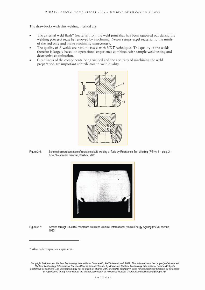
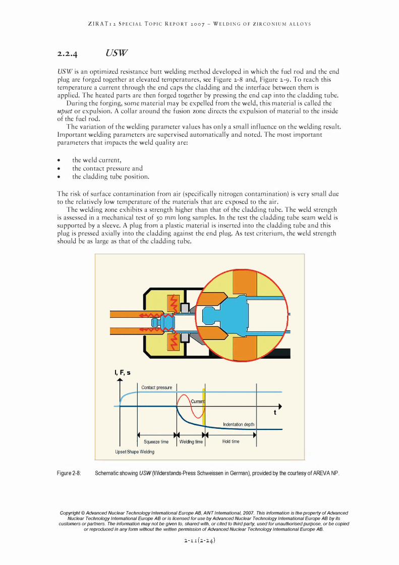
In Russia, Resistance (R) butt welding was developed in the 1970s, Figure 2-6. R welding has also been used on CANDU and Steam Generating Heavy Water Reactor (SCHWR) fuel rods for many years, Figure 2-7.
The favourable features of R welding are:
• It largely eliminates the melting of the cladding and the plug and, as a result of dynamic recrystallization, a fine-grained structure is formed at the site of joining the clad and the end plug by a diffusion bond.
• The extension of the HAZ by R welding is very small. • Virtually guaranteed freedom from contamination. • The use of weld condition monitoring as an on-line inspection technique.
Copyright © Advanced Nuclear Technology International Europe AB, ANT International, 2007. This information is the property of Advanced
Nuclear Technology International Europe AB or is licensed for use by Advanced Nuclear Technology International Europe AB by its customers or partners. The information may not be given to, shared with, or cited to third party, used for unauthorised purpose, or be copied
or reproduced in any form without the written permission of Advanced Nuclear Technology International Europe AB.
ZIRA Tr 2 SPECIAL TOPIC REPORT 2007 - WELDING OF ZIRCONIUM ALLOYS
The drawbacks with this welding method are:
• The external weld flash'4 (material from the weld j oint that has been squeezed out during the welding process) must be removed by machining. Newer setups expel material to the inside of the rod only and make machining unnecessary.
• The quality of R welds are hard to assess with NDT techniques. The quality of the welds therefor is largely based on operational experience combined with sample weld testing and destructive examination.
• Cleanliness of the components being welded and the accuracy of machining the weld preparation are important contributors to weld quality.
Figure 2-6:
Figure 2-7:
Schematic representation of resistance butt-welding of fuels by Resistance Butt Welding (RBW): 1 - plug, 2 -
tube; 3 - annular mandrel, Shishov, 2006.
Section through SGHWR resistance-weld end-closure, International Atomic Energy Agency (lAEA) , Vienna, 1983.
'4 Also called upset or expulsion.
Copyright © Advanced Nuclear Technology International Europe AB, ANT Intemational, 2007. This information is the property of Advanced
Nuclear Technology International Europe AB or is licensed for use by Advanced Nuclear Technology International Europe AB by its customers or partners. The information may not be given to, shared with, or cited to third party, used for unauthorised purpose, or be copied
or reproduced in any form without the written permission of Advanced Nuclear Technology International Europe AB.
ZIRA Tr 2 SPECIAL TOPIC REPORT 2007 - WELDING OF ZIRCONIUM ALLOYS
2.2·4 usw
USW is an optimized resistance butt welding method developed in which the fuel rod and the end plug are forged together at elevated temperatures, see Figure 2-8 and, Figure 2-9 . To reach this temperature a current through the end caps the cladding and the interface between them is applied. The heated parts are then forged together by pressing the end cap into the cladding tube.
During the forging, some material may be expelled from the weld, this material is called the upset or expulsion. A collar around the fusion zone directs the expulsion of material to the inside of the fuel rod.
The variation of the welding parameter values has only a small influence on the welding result. Important welding parameters are supervised automatically and noted. The most important parameters that impacts the weld quality are:
• the weld current, • the contact pressure and • the cladding tube position.
The risk of surface contamination from air ( specifically nitrogen contamination) is very small due to the relatively low temperature of the materials that are exposed to the air .
The welding zone exhibits a strength higher than that of the cladding tube. The weld strength is assessed in a mechanical test of 50 mm long samples. In the test the cladding tube seam weld is supported by a sleeve. A plug from a plastic material is inserted into the cladding tube and this plug is pressed axially into the cladding against the end plug. As test criterium, the weld strength should be as large as that of the cladding tube.
Figure 2-8:
I, F, s
I Contact pressure I
Squeeze time
Upset Shape Welding
t Indentation depth
Welding time Hold time
Schematic showing USW (Widerstands-Press Schweissen in German), provided by the courtesy of AREVA NP.
Copyright © Advanced Nuclear Technology International Europe AB, ANT Intemational, 2007. This information is the property of Advanced
Nuclear Technology International Europe AB or is licensed for use by Advanced Nuclear Technology International Europe AB by its customers or partners. The information may not be given to, shared with, or cited to third party, used for unauthorised purpose, or be copied
or reproduced in any form without the written permission of Advanced Nuclear Technology International Europe AB.
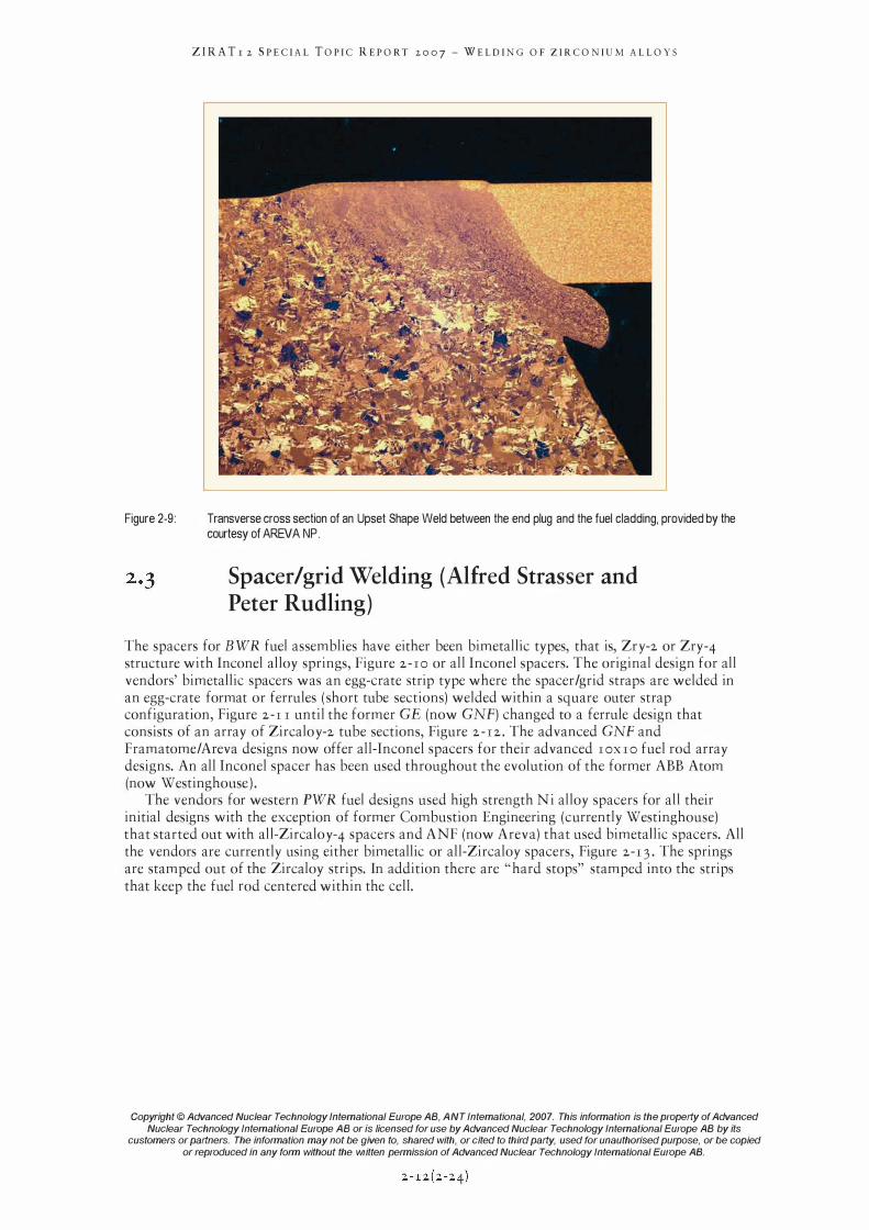
Figure 2-9:
ZIRA Tr 2 SPECIAL TOPIC REPORT 2007 - WELDING OF ZIRCONIUM ALLOYS
Transverse cross section of an Upset Shape Weld between the end plug and the fuel cladding, provided by the courtesy of AREVA NP.
Spacer/grid Welding (Alfred Strasser and Peter Rudling)
The spacers for BWR fuel assemblies have either been bimetallic types, that is, ZrY-2 or Zry-4 structure with Inconel alloy springs, Figure 2 -10 or all Inconel spacers. The original design for all vendors' bimetallic spacers was an egg-crate strip type where the spacer/grid straps are welded in an egg-crate format or ferrules ( short tube sections) welded within a square outer strap configuration, Figure 2-1 I until the former GE (now GNF) changed to a ferrule design that consists of an array of ZircaloY-2 tube sections, Figure 2 - 1 2 . The advanced GNF and Framatome/Areva designs now offer all-Inconel spacers for their advanced I OX I O fuel rod array designs. An all Inconel spacer has been used throughout the evolution of the former ABB Atom (now Westinghouse ) .
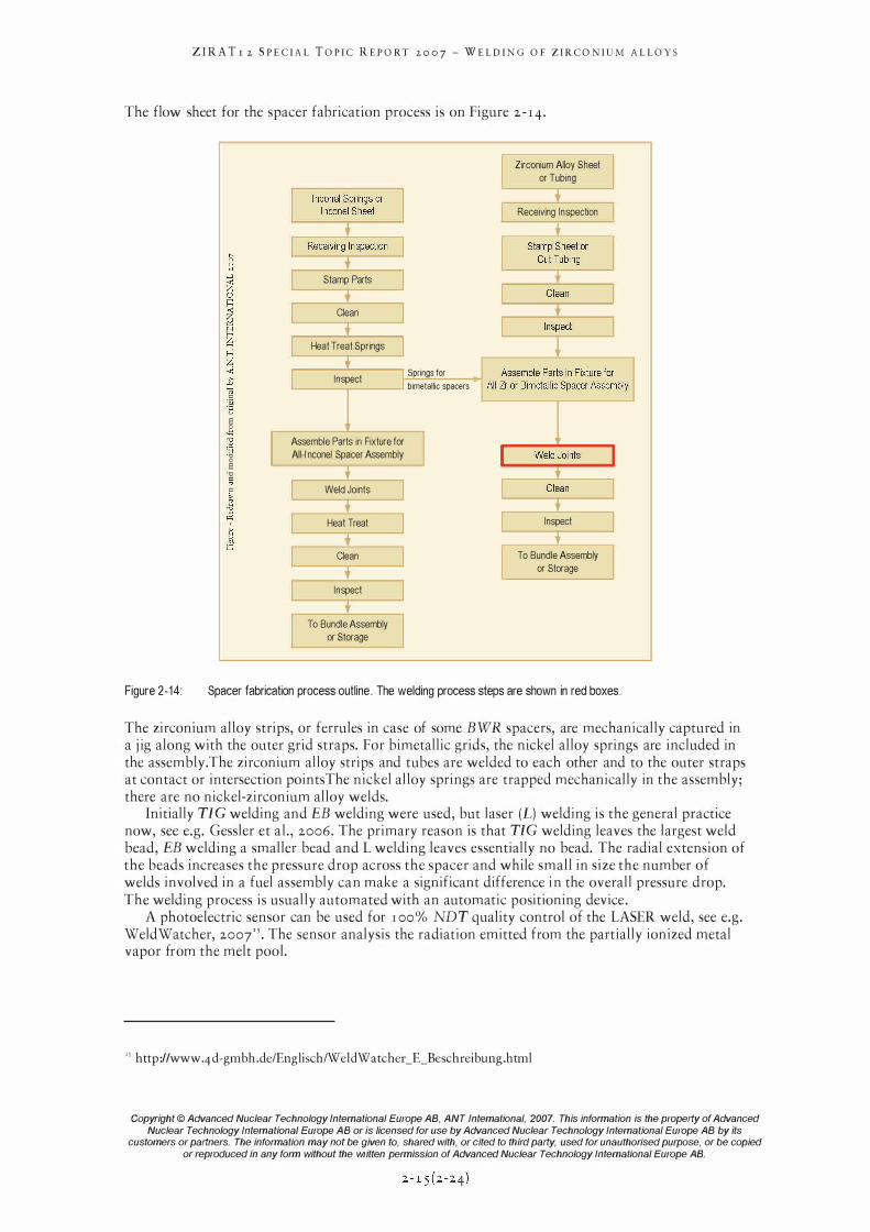
The vendors for western PWR fuel designs used high strength Ni alloy spacers for all their initial designs with the exception of former Combustion Engineering (currently Westinghouse) that started out with all-ZircaloY-4 spacers and ANF (now Areva) that used bimetallic spacers. All the vendors are currently using either bimetallic or all-Zircaloy spacers, Figure 2-13 . The springs are stamped out of the Zircaloy strips. In addition there are " hard stops" stamped into the strips that keep the fuel rod centered within the cell.
Copyright © Advanced Nuclear Technology International Europe AB, ANT Intemational, 2007. This information is the property of Advanced
Nuclear Technology International Europe AB or is licensed for use by Advanced Nuclear Technology International Europe AB by its customers or partners. The information may not be given to, shared with, or cited to third party, used for unauthorised purpose, or be copied
or reproduced in any form without the written permission of Advanced Nuclear Technology International Europe AB.
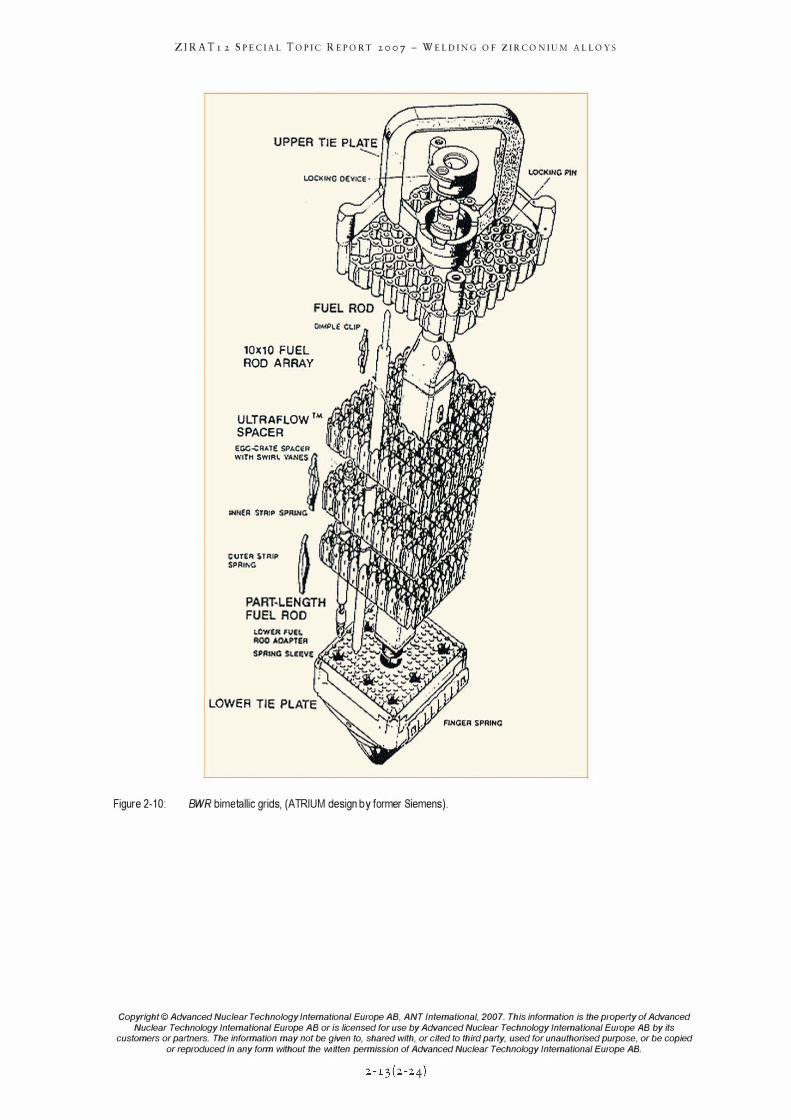
Figure 2-10:
ZIRA Tr 2 SPECIAL TOPIC REPORT 2007 - WELDING OF ZIRCONIUM ALLOYS
I.OCKII(C DEvice · .
OIMPl� CLIP
10)(10 F U EL � I ROD A RRAY �
;
U LTRAFLOW ™ llJYJ'UJ."'"<I SPACER
EOO..cRATE SPkC£R WITH SWIRL \,ANf;.S � II:IlInl,,""".L��1I
� J ) .... _,rv'I.'Wn. INNeA STRIP S PRlNC> lI"lMilI�.Ii''MJ�'"
CIJTEA STRIP J� SPRING �
LOWER
BWR bimetallic grids, (ATRIUM design by former Siemens).
Copyright © Advanced Nuclear Technology International Europe AB, ANT Intemational, 2007. This information is the property of Advanced
Nuclear Technology International Europe AB or is licensed for use by Advanced Nuclear Technology International Europe AB by its customers or partners. The information may not be given to, shared with, or cited to third party, used for unauthorised purpose, or be copied
or reproduced in any form without the written permission of Advanced Nuclear Technology International Europe AB.
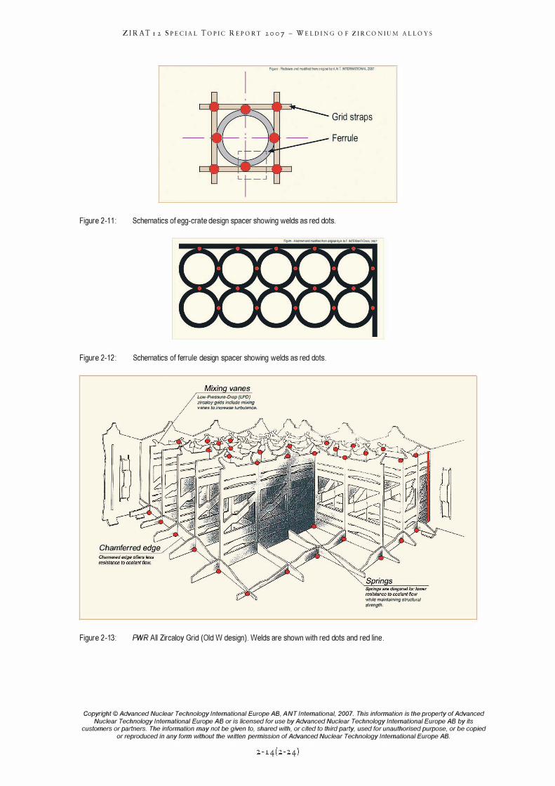
Figure 2-1 1 :
Figure 2-12 :
ZIRA Tr 2 SPECIAL TOPIC REPORT 2007 - WELDING OF ZIRCONIUM ALLOYS
Figure · Redrawn and modifie(j from Ofignal by A.N.1 INTERNATIONAlZOO7
Grid straps
Ferrule
Schematics of egg-crate design spacer showing welds as red dots.
t'9l"·Reonwna'ldmodlledfrom�byA.N.T. INTERNATIONAl2007
Schematics of ferrule design spacer showing welds as red dots.
vanes Low-Pressure-Drop (LPD) zircaloy grids incfudc mixing vanes to inC1'e8Se turbulence.
Chamferred
Figure 2-13:
while maintaining stroctuf£J1 strength.
PWR All Zircaloy Grid (Old W design). Welds are shown with red dots and red line.
Copyright © Advanced Nuclear Technology International Europe AB, ANT Intemational, 2007. This information is the property of Advanced
Nuclear Technology International Europe AB or is licensed for use by Advanced Nuclear Technology International Europe AB by its customers or partners. The information may not be given to, shared with, or cited to third party, used for unauthorised purpose, or be copied
or reproduced in any form without the written permission of Advanced Nuclear Technology International Europe AB.
ZIRA Tr 2 SPECIAL TOPIC REPORT 2007 - WELDING OF ZIRCONIUM ALLOYS
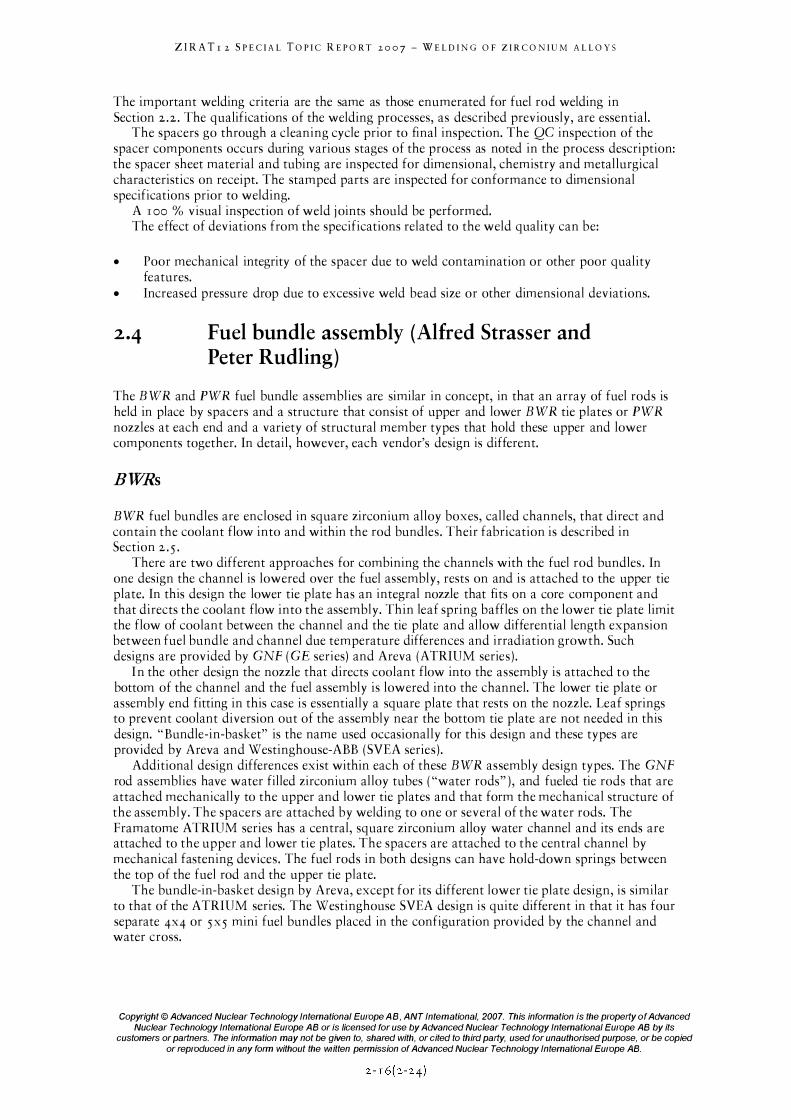
The flow sheet for the spacer fabrication process is on Figure 2 -14 .
Figure 2-14:
"-0 � L � Stamp Parts J � 0 r---
r:: C � «: Clean Z cO '" � Heat Treat Springs � :i r-.,: '" Inspect .D ""ii l c '51 "§ S 0 '"' [ "';l Assemble Parts in Fixture for
:-B All-I nconel Spacer Assembly "0 0
S "0 §
I I c Weld Joints � "" f � C Heat Treat J � £ on p;
C J Clean
f L Inspect I
To Bundle Assembly
or Storage
Springs for bimetallic spacers
Zirconium Alloy Sheet
or Tubing
Receiving Inspection
Inspect
To Bundle Assembly
or Storage
Spacer fabrication process outline. The welding process steps are shown in red boxes.
The zirconium alloy strips, or ferrules in case of some BWR spacers, are mechanically captured in a j ig along with the outer grid straps. For bimetallic grids, the nickel alloy springs are included in the assembly. The zirconium alloy strips and tubes are welded to each other and to the outer straps at contact or intersection points The nickel alloy springs are trapped mechanically in the assembly; there are no nickel-zirconium alloy welds.
Initially TIC welding and EB welding were used, but laser (L) welding is the general practice now, see e.g. Gessler et aI., 2006. The primary reason is that TIC welding leaves the largest weld bead, EB welding a smaller bead and L welding leaves essentially no bead. The radial extension of the beads increases the pressure drop across the spacer and while small in size the number of welds involved in a fuel assembly can make a significant difference in the overall pressure drop. The welding process is usually automated with an automatic positioning device .
A photoelectric sensor can be used for 1 00% NDT quality control of the LASER weld, see e.g. WeldWatcher, 200]'5 . The sensor analysis the radiation emitted from the partially ionized metal vapor from the melt pool.
'5 http://www.4d-gmbh.delEnglischlW eldW atchecE_Beschreibung.html
Copyright © Advanced Nuclear Technology International Europe AB, ANT Intemational, 2007. This information is the property of Advanced
Nuclear Technology International Europe AB or is licensed for use by Advanced Nuclear Technology International Europe AB by its customers or partners. The information may not be given to, shared with, or cited to third party, used for unauthorised purpose, or be copied
or reproduced in any form without the written permission of Advanced Nuclear Technology International Europe AB.
ZIRATr 2 SPECIAL TOPIC REPORT 2007 - WELDING OF ZIRCONIUM ALLOYS
The important welding criteria are the same as those enumerated for fuel rod welding in Section 2 .2 . The qualifications of the welding processes, as described previously, are essential.
The spacers go through a cleaning cycle prior to final inspection. The QC inspection of the spacer components occurs during various stages of the process as noted in the process description: the spacer sheet material and tubing are inspected for dimensional, chemistry and metallurgical characteristics on receipt. The stamped parts are inspected for conformance to dimensional specifications prior to welding.
A 1 00 % visual inspection of weld j oints should be performed. The effect of deviations from the specifications related to the weld quality can be:
• Poor mechanical integrity of the spacer due to weld contamination or other poor quality features.
• Increased pressure drop due to excessive weld bead size or other dimensional deviations.
2.4 Fuel bundle assembly (Alfred Strasser and Peter Rudling)
The BWR and PWR fuel bundle assemblies are similar in concept, in that an array of fuel rods is held in place by spacers and a structure that consist of upper and lower BWR tie plates or PWR nozzles at each end and a variety of structural member types that hold these upper and lower components together. In detail, however, each vendor's design is different.
BWRs
BWR fuel bundles are enclosed in square zirconium alloy boxes, called channels, that direct and contain the coolant flow into and within the rod bundles. Their fabrication is described in Section 2 . 5 .
There are two different approaches for combining the channels with the fuel rod bundles . In one design the channel is lowered over the fuel assembly, rests on and is attached to the upper tie plate. In this design the lower tie plate has an integral nozzle that fits on a core component and that directs the coolant flow into the assembly. Thin leaf spring baffles on the lower tie plate limit the flow of coolant between the channel and the tie plate and allow differential length expansion between fuel bundle and channel due temperature differences and irradiation growth. Such designs are provided by GNF (GE series) and Areva (ATRIUM series ) .
In the other design the nozzle that directs coolant flow into the assembly is attached to the bottom of the channel and the fuel assembly is lowered into the channel. The lower tie plate or assembly end fitting in this case is essentially a square plate that rests on the nozzle. Leaf springs to prevent coolant diversion out of the assembly near the bottom tie plate are not needed in this design. "Bundle-in-basket" is the name used occasionally for this design and these types are provided by Areva and Westinghouse-ABB (SVEA series) .
Additional design differences exist within each of these BWR assembly design types. The GNF rod assemblies have water filled zirconium alloy tubes ( "water rods" ), and fueled tie rods that are attached mechanically to the upper and lower tie plates and that form the mechanical structure of the assembly. The spacers are attached by welding to one or several of the water rods. The Framatome ATRIUM series has a central, square zirconium alloy water channel and its ends are attached to the upper and lower tie plates. The spacers are attached to the central channel by mechanical fastening devices. The fuel rods in both designs can have hold-down springs between the top of the fuel rod and the upper tie plate.
The bundle-in-basket design by Areva, except for its different lower tie plate design, is similar to that of the ATRIUM series. The Westinghouse SVEA design is quite different in that it has four separate 4X4 or 5X5 mini fuel bundles placed in the configuration provided by the channel and water cross.
Copyright © Advanced Nuclear Technology International Europe AB, ANT International, 2007. This information is the property of Advanced
Nuclear Technology International Europe AB or is licensed for use by Advanced Nuclear Technology International Europe AB by its customers or partners. The information may not be given to, shared with, or cited to third party, used for unauthorised purpose, or be copied
or reproduced in any form without the written permission of Advanced Nuclear Technology International Europe AB.
ZIRA Tr 2 SPECIAL TOPIC REPORT 2007 - WELDING OF ZIRCONIUM ALLOYS
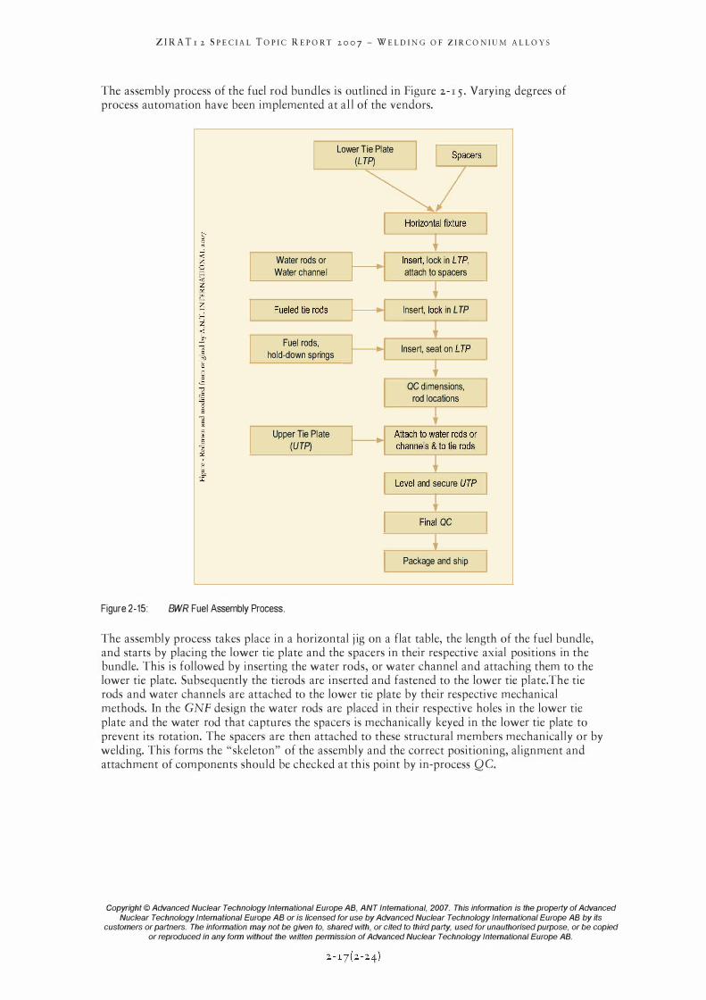
The assembly process of the fuel rod bundles is outlined in Figure 2- 1 5 . Varying degrees of process automation have been implemented at all of the vendors.
Figure 2-15:
[ Water rods or
Water channel
Lower Tie Plate (LTP)
Iinsert, lock in LTP'l L attach to spacers
.---
� ___ F u_
e_
l e_
d_
t_
i e_
ro_
d_
s __ �� Insert, 10�k in L TP
Fuel rods,
hold-down springs
Upper Tie Plate
(UTP)
BWR Fuel Assembly Process.
Insert, seat on LTPI t
I QC dimensions, J L rod locations
l,:evel and secure UT� F;'� QC
Package and ship
The assembly process takes place in a horizontal j ig on a flat table, the length of the fuel bundle, and starts by placing the lower tie plate and the spacers in their respective axial positions in the bundle. This is followed by inserting the water rods, or water channel and attaching them to the lower tie plate. Subsequently the tierods are inserted and fastened to the lower tie plate.The tie rods and water channels are attached to the lower tie plate by their respective mechanical methods. In the GNF design the water rods are placed in their respective holes in the lower tie plate and the water rod that captures the spacers is mechanically keyed in the lower tie plate to prevent its rotation. The spacers are then attached to these structural members mechanically or by welding. This forms the "skeleton" of the assembly and the correct positioning, alignment and attachment of components should be checked at this point by in-process Q C.
Copyright © Advanced Nuclear Technology International Europe AB, ANT Intemational, 2007. This information is the property of Advanced
Nuclear Technology International Europe AB or is licensed for use by Advanced Nuclear Technology International Europe AB by its customers or partners. The information may not be given to, shared with, or cited to third party, used for unauthorised purpose, or be copied
or reproduced in any form without the written permission of Advanced Nuclear Technology International Europe AB.
ZIRA Tr 2 SPECIAL TOPIC REPORT 2007 - WELDING OF ZIRCONIUM ALLOYS
PWRs
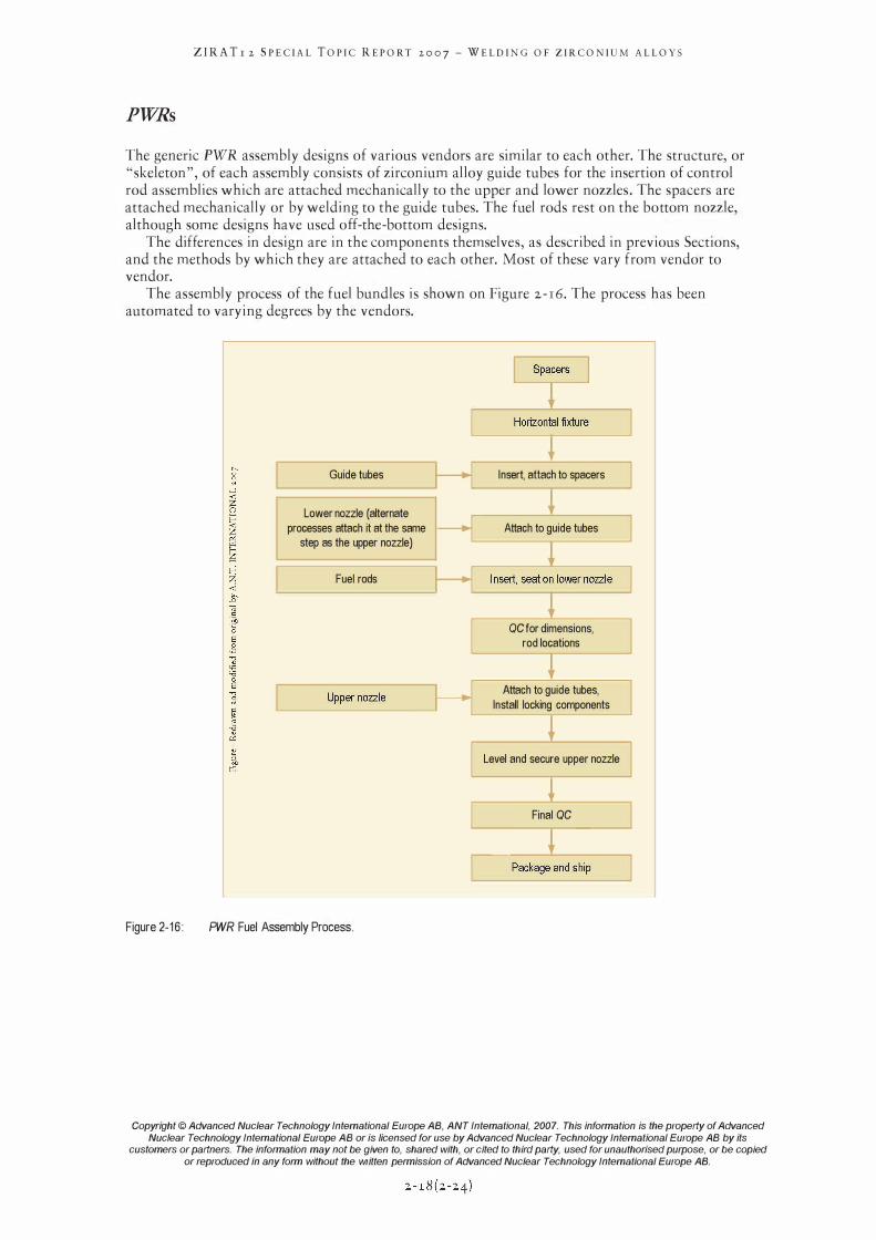
The generic PWR assembly designs of various vendors are similar to each other. The structure, or "skeleton", of each assembly consists of zirconium alloy guide tubes for the insertion of control rod assemblies which are attached mechanically to the upper and lower nozzles . The spacers are attached mechanically or by welding to the guide tubes. The fuel rods rest on the bottom nozzle, although some designs have used off-the-bottom designs.
The differences in design are in the components themselves, as described in previous Sections, and the methods by which they are attached to each other. Most of these vary from vendor to vendor.
The assembly process of the fuel bundles is shown on Figure 2 - r6. The process has been automated to varying degrees by the vendors.
Figure 2-16 :
Guide tubes
Lower nozzle (alternate processes attach it at the sarne
step as the upper nozzle)
Fuel rods
[
T Insert, attach to spacers
T Attach to guide tubes
QC for dirnensions, rod locations
T
]
] � -----, _ Attach to guide tubes,
L� ____ U_p_pe_r_n_o_zz
_le __ �_----, Install locking cornponents
PWR Fuel Assembly Process.
�------'Jr---� Level and secure upper nozzle
L Final QC � [ 2,", J
Copyright © Advanced Nuclear Technology International Europe AB, ANT Intemational, 2007. This information is the property of Advanced
Nuclear Technology International Europe AB or is licensed for use by Advanced Nuclear Technology International Europe AB by its customers or partners. The information may not be given to, shared with, or cited to third party, used for unauthorised purpose, or be copied
or reproduced in any form without the written permission of Advanced Nuclear Technology International Europe AB.
ZIRATr 2 SPECIAL TOPIC REPORT 2007 - WELDING OF ZIRCONIUM ALLOYS
3 Quality management (Peter Rudling and Alfred Strasser)
Introduction
Quality -The most common interpretation of the term Quality in everyday language is noninferiority, superiority or usefulness of something.
Many different techniques and concepts have evolved over the years to improve product or service quality, including Quality Assurance (QA), Quality Management Systems (QMS), and Total Quality Management (TQM).
Most discussions of quality refer to a finished product, wherever it is in the process. Inspection, which is what quality insurance usually means, is historical, since the work is done. The best way to think about quality is in process control. If the process is under control, inspection is not necessary.
In the past, when we one tried to improve quality, typically defined as producing fewer defective parts, it usually did so at the expense of increased cost, increased task time, longer cycle time, etc.
However, when modern quality techniques are applied correctly to business, engineering, manufacturing or assembly processes, all aspects of quality - customer satisfaction and fewer defects/errors and cycle time and task time/productivity and total cost, etc.- must all improve or, if one of these aspects does not improve, it must at least stay stable and not decline.
QA comprises all those planned and systematic actions necessary to provide adequate confidence that a structure, system, or component will perform satisfactorily in service. QA covers all activities from design, development, production, installation, servicing to documentation. It introduced the sayings "fit for purpose" and "do it right the first time". It includes the regulation of the quality of raw materials, assemblies, products and components; services related to production; and management, production, and inspection processes. QA assures the existence and effectiveness of procedures that attempt to make sure - in advance - that the expected levels of quality will be reached.
The "parent" of all basic QA requirements in the nuclear field was established by the US Government's Code of Federal Regulations (CFR) Title 10, Chapter 1. These documents set forth the rules and regulations that govern the actions of the Nuclear Regulatory Commission (NRC) and the applicable licensees. The CFR requirements are general and the detailed regulations and standards are evolved from these. The most relevant regulations to the fuel fabrication processes described in this Handbook are contained in Appendix B to IoCFR50, "Quality Assurance Criteria for Nuclear Power Plants and Fuel Processing Plants", issued in I 970. These criteria, in turn, were originally developed, prior to this time, by the US naval nuclear propulsion program.
Appendix B has become the basic "constitution" of QA, as its IS criteria cover all of the QA requirements. Like other types of "constitutions", this one outlines the general principles and actions required of a QA system and are open to very broad interpretation. More detailed guidance was needed and this task was assumed by various standards organizations. The IS criteria have been adopted in most countries, in one form or another, by their regulatory bodies, as well as their standards organizations.
In the US, the task of providing detailed guidance was assumed by the American National Standards Institute (ANSI) and the American Society of Mechanical Engineers (ASME) and for some issues by the NRC's Regulatory Guides. The initial ANSI Standard N45.2 was the equivalent of Appendix B and its series of detailed standards were numbered N45.2 with additional numerical digits. The NRC staff reviewed each ANSI standard and subsequent to its issuance issued a parallel Regulatory Guide, which either endorsed or modified the ANSI standard. Subsequently a joint standard was issued with the ASME, NQA-I, in 1979, which had essentially the same structure as its predecessor. The latest version of this standard was issued in the year 2000.
Copyright © Advanced Nuclear Technology International Europe AB, ANT International, 2007. This information is the property of Advanced
Nuclear Technology International Europe AB or is licensed for use by Advanced Nuclear Technology International Europe AB by its customers or partners. The information may not be given to, shared with, or cited to third party, used for unauthorised purpose, or be copied
or reproduced in any form without the written permission of Advanced Nuclear Technology International Europe AB.
ZIRATr 2 SPECIAL TOPIC REPORT 2007 - WELDING OF ZIRCONIUM ALLOYS
The international community developed its series of standards with the International Organization for Standardization (ISO) starting in the 1980s and these are also based on the criteria outlined in loCFR50, Appendix B. The ISO technical committees have memberships from the countries interested in the special topics covered by each standard. Both governmental and nongovernmental organizations take part in developing the standards. Publication of a standard req uires approval by a minimum of 75% of the members. The ISO 9000 series of standards are applicable to fuel fabrication. The recent issues also combined the standards with ANSI and the American Society for Quality (ASQ) and their latest publications are from the year 2000.
QCsystems are those quality assurance actions which provide a means to control and measure the characteristics of an item, process or facility in accordance with established requirements. QC is a part of QA, and for nuclear fuel can be considered as process control, product inspection and associated activities. QA is a management system ensuring that all important activities are accomplished in a planned, systematic and controlled manner to assure the satisfactory performance of components. QC measures the characteristics of a process, a piece of equipment and a component to endure that they meet the established requirements. One of the functions of QA is to assure that the QC process is functioning satisfactorily.
Quality managements system
QMS can be defined as a set of policies, processes and procedures required for planning and Execution (Production I Development I Service) in the core business area of an Organization. QMS integrates the various internal processes within the organization and intends to provide a process approach for project execution. QMS enables the organizations to identify, measure, control and improve the various core business processes that will ultimately lead to improved business performance. Today an integrated quality and environmental management system is being used, Dyllick & Hummel, 1996.
The International Organization for Standardization's ISO 9000 series (which is a process modell) describes standards for a QMS addressing the processes surrounding the design, development and delivery of a general product or service. Organisations can participate in a continuing certification process to demonstrate their compliance with the standard.
Today, nuclear fuel vendors and subcontractors must have a quality management system according to the international standard ISO 9000:2000, described more in the following subsections.
3.2•1 Q9000, quality management systems - fundamentals and vocabulary
The ANSIIISOIASQ Q9000-2000 standard, "Quality Management Systems - Fundamentals and Vocabulary", describes the fundamentals of and specifies the terminology for quality management systems.
This set of standards has changed the emphasis on the terminology for "quality assurance" to "quality management", the latter being a term that covers a broad area of which "quality assurance" is a part.
Copyright © Advanced Nuclear Technology International Europe AB, ANT International, 2007. This information is the property of Advanced
Nuclear Technology International Europe AB or is licensed for use by Advanced Nuclear Technology International Europe AB by its customers or partners. The information may not be given to, shared with, or cited to third party, used for unauthorised purpose, or be copied
or reproduced in any form without the written permission of Advanced Nuclear Technology International Europe AB.
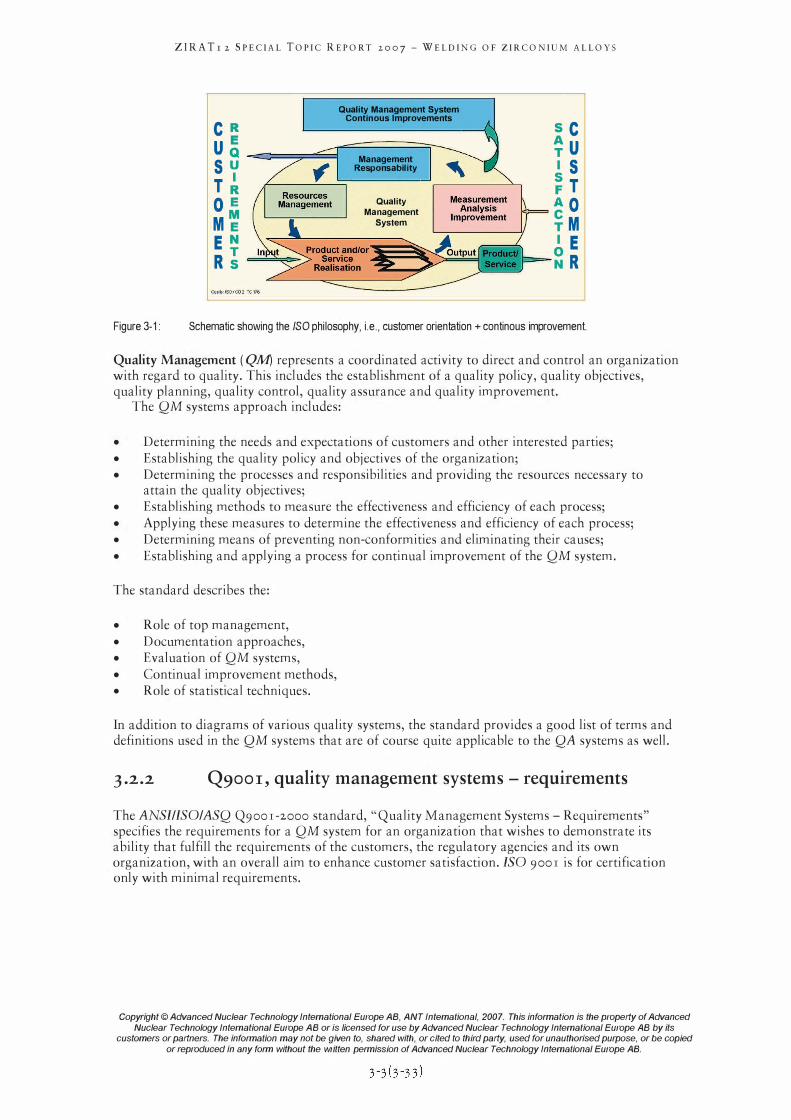
ZIRA Tr 2 SPECIAL TOPIC REPORT 2007 - WELDING OF ZIRCONIUM ALLOYS
CR U� 5 u
T� o E M� E N R�
Quality Management System Continous Improvements
Management Responsability
Quality Management
System
SC �U 15 �T AO ¥M I E �R
Figure 3-1: Schematic showing the ISO philosophy, i.e., customer orientation + continous improvement.
Quality Management (QA1) represents a coordinated activity to direct and control an organization with regard to quality. This includes the establishment of a quality policy, quality objectives, quality planning, quality control, quality assurance and quality improvement.
The QM systems approach includes:
• Determining the needs and expectations of customers and other interested parties; • Establishing the quality policy and objectives of the organization; • Determining the processes and responsibilities and providing the resources necessary to
attain the quality objectives; • Establishing methods to measure the effectiveness and efficiency of each process; • Applying these measures to determine the effectiveness and efficiency of each process; • Determining means of preventing non-conformities and eliminating their causes; • Establishing and applying a process for continual improvement of the QM system.
The standard describes the:
• Role of top management, • Documentation approaches, • Evaluation of QM systems, • Continual improvement methods, • Role of statistical techniques.
In addition to diagrams of various quality systems, the standard provides a good list of terms and definitions used in the QM systems that are of course quite applicable to the QA systems as well.
3.2.2 Q900I, quality management systems - requirements
The ANSIIISOIASQ Q900r-2000 standard, "Quality Management Systems - Requirements" specifies the requirements for a QM system for an organization that wishes to demonstrate its ability that fulfill the requirements of the customers, the regulatory agencies and its own organization, with an overall aim to enhance customer satisfaction. ISO 900r is for certification only with minimal requirements.
Copyright © Advanced Nuclear Technology International Europe AB, ANT Intemational, 2007. This information is the property of Advanced
Nuclear Technology International Europe AB or is licensed for use by Advanced Nuclear Technology International Europe AB by its customers or partners. The information may not be given to, shared with, or cited to third party, used for unauthorised purpose, or be copied
or reproduced in any form without the written permission of Advanced Nuclear Technology International Europe AB.
4
ZIRATr 2 SPECIAL TOPIC REPORT 2007 - WELDING OF ZIRCONIUM ALLOYS
Factors that can affect the quality of welds (Peter Rudling)
Introduction
The quality of a weld is most often judged by the strength of the weld and the strength of the material around it. For zirconium components in addition to the strenght of the weld, the corrosion performance in the reactor is very important.To obtain a high quality weld in a Zirconium alloy part that will be exposed in a nuclear reactor the following factors need to be considered:
• Design of weld joints and dimensional tolerance limits of the parts to be joined. • Cleaning of weld joints and adjacent areas prior to welding. Contamination can lead to
welds with poor strenght and lor poor corrosion resistance. • Atmosphere control during many of the zirconium welding processes must be strictly
controlled to keep uptake of especially nitrogen and to a lesser extent oxygen at very low levels. In reactor corrosion resistance can be impaired when these gases enter the weld.
• Weldability of the employed materials. Microstuctural changes in and near the weld may affect the strenght and the corrosion properties. Binary Zirconium-Niobium alloys are more sensative than either ternary Zr-Nb-Sn alloys or the Zircaloys.
• Weld process In the, TIC, EB, and LB welding processes, alloy depletion must be considered. The time-temperature history of the weld, which affects the microstructural transformations that take place. The formation of some microstructures and metal phases needs to be avoided.
• Adequate Quality Control of the entire welding process including equipment and personnel, as discussed in the previous chapter, needs to be maintained.
A detailed discussion of these items follows. Out-of-pile autoclave corrosion tests are normally used to gauge the in-reactor corrosion
behavior of Zirconium alloy components. However, a material/weld which shows good corrosion performance out-of-pile may still show poor corrosion performance in-reactor. Only when the out-of-pile test has been qualified and the test has been performed within its bounding conditions and the results have been verified against in-reactor behavior can the test be relied upon to adequately predict long term in-reactor corrosion performance.
A qualified out-of-pile test means that the following boundary conditions are identified:
• The out-of-pile test environment (temperature, pressure, time, corrosion medium characteristics, etc.)
• The material/weld chemistry and microstructures for which the out-of-pile test is valid.
The reason that the out-of-pile corrosion test may not able to predict the corrosion performance of a material/weld in-reactor is that the corrosion mechanism in the out-of-pile test is different from that occurring in the reactor. However, if the out-of-pile corrosion test is performed within the bounding conditions, it is likely that the result of the test accurately mirrors the in-reactor corrosion mechanism. It is important to point out that the current out-of-pile corrosion tests used today were developed for ZrY-2 and -4 materials. In the case of PWRs, Zry-4 materials are not much used anymore for fuel rods.
Copyright © Advanced Nuclear Technology International Europe AB, ANT International, 2007. This information is the property of Advanced
Nuclear Technology International Europe AB or is licensed for use by Advanced Nuclear Technology International Europe AB by its customers or partners. The information may not be given to, shared with, or cited to third party, used for unauthorised purpose, or be copied
or reproduced in any form without the written permission of Advanced Nuclear Technology International Europe AB.
ZIRATr 2 SPECIAL TOPIC REPORT 2007 - WELDING OF ZIRCONIUM ALLOYS
The main problemwith fusion welding is to produce welded joints free of discontinuities, i. e., without microcracks; defects similar to cracks; poor penetration; different kinds of inclusions (e.g. fuel) in the weld; hair-line non-metallic inclusions in bars used for plugs; porosity in welds, weld overhang and gas pockets.
In all types of fusion welds there is a risk that alloying elements with a lower melting temperature and high vapor pressure compared to that of Zirconium will evaporate during welding resulting in a fusion zone with a significantly lower alloying content compared to that of the non-melted material.
The fusion welding atmosphere purity is critical since the hot or molten zirconium alloy will absorb oxygen and nitrogen rapidly. The weld quality of Nb alloys (M5, EIIO) is particularly sensitive to nitrogen pickup. Nitrogen contamination of the weld significantly reduces the onreactor corrosion resistance. The atmosphere in the weld chamber must be monitored so as not to exceed the allowable limits on nitrogen, oxygen and moisture. When vacuum is used, as for exemple during EB welding,a maximum pressure limit must be observed. The high pressure TIC welding process frequently uses small additions of argon gas to help start the arc in the helium atmosphere. Since excessive low thermal conductivity argon can degrade the high thermal conductivity of the helium atmosphere in the fuel rod, the potential of excess argon dilution must be controlled.
An advantage of resistance welding is that it can be performed under any gas pressure without undue difficulties, and often it can be done in air. This is because the time- temperature cycle of resistance welding is extremely short, and material next to the weld area remains rathercool. At the plane of connection between the materials to be welded Some material may be squeezed out, expulsion, from the joint between the parts. This material may be contaminated. But when this expulsion is removed by machining there will be no negative impact on the corrosion performance of the weld since the bulk material underneath the expulsion is not contaminated.
Welding methods that involve the melting of metal at the site of the joint necessarily are prone to shrinkage as the fusion zone solidifies and the heated metal cools. Shrinkage, in turn, can introduce residual stresses24 and distortion. Distortion can pose a major problem,especially with large components. Other methods of limiting distortion, such as clamping the workpieces in place, cause the buildup of residual stress in the weld and in the heat-affected zone. These stresses can reduce the strength of the joint but also result in dimensional changes of the component due to relaxation of the residual stresses due to in-reactor creep and neutron irradiation. To reduce the amount of distortion and residual stresses, the amount of heat input should be limited as much as possible. The residual stresses can also be relaxed by an a ppropria te heat treatment of the welded component (such as e.g. the hot sizing process of the fuel outer channel) before in-reactor irradia tion.
There are essentially three types of weld defects in Zirconium alloys that are of a concern. The defects can be grouped dependant upon the impact of these defects on the performance of the welded component, as follows:
I) Excessive weld bead size, Figure 4-1,: can cause the following problems: a) When the weld overhang of fuel rod endcaps is to large,when, difficulties may be
encountered in loading the fuel rods into the fuel grids/spacers without plastically deforming the grid/spacer springs.
b) excessive grid/spacer pressure drop may be the result when the weld bead size of the grid/spacer intersections is larger than it should be.
24 Residual stresses are stresses that remain after the original cause of the stresses (external forces, heat gradient) has been removed. They remain along a cross section of the component, even without the external cause. Residual stresses occur for a variety of reasons, including inelastic deformations and heat treatment. Heat from welding may cause localized expansion, which is taken up during welding by either the molten metal or the placement of parts being welded. When the finished weldment cools, some areas cool and contract more than others, leaving residual stresses.
Copyright © Advanced Nuclear Technology International Europe AB, ANT International, 2007. This information is the property of Advanced
Nuclear Technology International Europe AB or is licensed for use by Advanced Nuclear Technology International Europe AB by its customers or partners. The information may not be given to, shared with, or cited to third party, used for unauthorised purpose, or be copied
or reproduced in any form without the written permission of Advanced Nuclear Technology International Europe AB.
ZIRATr 2 SPECIAL TOPIC REPORT 2007 - WELDING OF ZIRCONIUM ALLOYS
2) Defects causing poor mechanical performance of the weld leading to: a) inferior mechanical performance of the grid/spacer. This is a concern especially for
PWR fuel assemblies since the grid/spacers strength may limit the PWR fuel assembly performance during a seismic event
b) inferior mechanical performance of the fuel outer channel (this is important for BWR fuel assemblies since the outer channel strength may limit the BWR fuel assembly
c) Spacers/grids moving upwards in the FA due to the flowing coolant when the welds that attach the grids/spacers to the FA structure have failed.
3) Fuel rod leakage due to a defect in the end cap weld.
Defects in the above categories are:
• inadequate weld penetration2" • concavity (Figure 4-2), • undercut (Figure 4-3), • mismatch (Figure 4-4), • cracks2\ • pores27 (Figure 4-5), • excessive grain growth in the HAZ, • orientation of hydrides2s • weld contamination, vaporisation of alloying elements or unfavourable metallurgical
structure (as a result of the heating and cooling welding cycles) that could result in a low strength weld or enhanced weld zone corrosion which could all result in a leaking fuel rod
25 Incomplete penetration of the weld through the thickness of the joint. 26 Cracks can be defined as linear ruptures under stress. Based on the location and orientation of the cracks with respect to weld joint geometry, they are classified as longitudinal cracks, transverse cracks, toe cracks, crater cracks etc Depending on the temperature at which they form, cracks are termed as hot cracks or cold cracks. Hot cracks are intergranular and forms in the weldment during solidification or before the weld has completelysolidified. Cold cracks are transgranular and form in the weldments after completion of solidification. 27 Porosity is the presence of gas pockets or voids (usually spherical in shape) in a weld which are caused by the entrapment of gases evolved during the solidification of the metal. Types of porosities include isolated pores, scattered pores, worm holes etc. Worm holes are the blow holes that result from progressive evolution of gases during freezing. 28 Hydrogen (absorbed from the hydrogen produced through the corrosion reaction between the zirconium alloy and the coolant in reactor) in excess of about 100 wtppm may precipitate out together with Zirconium to form Zirconium hydrides. At room temperature and even at elevated temperature zirconium hydrides are quite brittle. The largest embrittlement effect of the hydrides occurs if they are oriented perpendicular to the largest tensile stress. The orientation of the zirconium hydrides depends on stresses and texture both of which are significantly impacted by the welding process.
Copyright © Advanced Nuclear Technology International Europe AB, ANT International, 2007. This information is the property of Advanced
Nuclear Technology International Europe AB or is licensed for use by Advanced Nuclear Technology International Europe AB by its customers or partners. The information may not be given to, shared with, or cited to third party, used for unauthorised purpose, or be copied
or reproduced in any form without the written permission of Advanced Nuclear Technology International Europe AB.
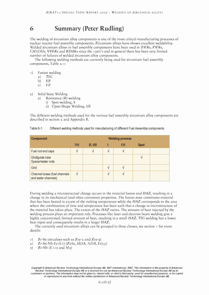
ZIRA Tr 2 SPECIAL TOPIC REPORT 2007 - WELDING OF ZIRCONIUM ALLOYS
6 Summary (Peter Rudling)
The welding of zirconium alloy components is one of the most critical manufacturing processes of nuclear reactor fuel assembly components. Zirconium alloys have shown excellent weldability. Welded zirconium alloys in fuel assembly components have been used in BWRs, PWRs, CANDUs, VVERs and RBMKs since the 1960's and in general there has been very limited number of failures of welded zirconium alloy components.
The following welding methods are currently being used for zirconium fuel assembly components, Table 2-1:
1) Fusion welding a) TIC b) EB c) LB
2) Solid State Welding a) Resistance (R) welding
i) Spot welding, S ii) Upset Shape Welding, US
The different welding methods used for the various fuel assembly zirconium alloy components are described in section 2 and Appendix B.
Table 6-1: Different welding methods used for manufacturing of different Fuel Assembly components.
Component Welding process
TlG R,US L EB Spot
Fuel rod end caps '-l '-l '-l '-l
Grid/guide tube '-l Spacerlwater rods
Grid '-l '-l
Channel boxes (fuel channels '-l '-l '-l and water channels)
During welding a microstructual change occurs in the material fusion and HAZ, resulting in a change in its mechanical (and often corrosion) properties. The fusion zone constitutes material that has been heated in excess of the melting temperature while the HAZ corresponds to the area where the combination of time and temperature has been such that a change in microstructure of the material has taken place. The extent of the HAZ varies. The amount of heat injected by the welding process plays an important role. Processes like laser and electron beam welding give a highly concentrated, limited amount of heat, resulting in a small HAZ. TIC welding has a lower heat input and consequently results in a larger HAZ.
The currently used zirconium alloys can be grouped in three classes, see section 1 for more details:
1) Zr-Sn (zircaloys such as ZrY-2 and ZrY-4) 2) Zr-Sn-Nb-Fe-(Cr) (Zirlo, MDA, NDA, E63 5) 3) Zr-Nb (EII0 and M5)
Copyright © Advanced Nuclear Technology International Europe AB, ANT Intemational, 2007. This information is the property of Advanced
Nuclear Technology International Europe AB or is licensed for use by Advanced Nuclear Technology International Europe AB by its customers or partners. The information may not be given to, shared with, or cited to third party, used for unauthorised purpose, or be copied
or reproduced in any form without the written permission of Advanced Nuclear Technology International Europe AB.
ZIRA Tr 2 SPECIAL TOPIC REPORT 2007 - WELDING OF ZIRCONIUM ALLOYS
The corrosion performance of both Zircaloys (e.g. ZrY-2) and Zr-Nb alloys are very sensitive to its microstructure which is a result of chemical composition and thermal treatment (due to the welding process), see also Section 4. The weld fusion and the heat affected zone represent a large variety range of heat treatments. The fusion zone has reached the highest temperature and has had the highest cooling rates while the area in the HAZ farthest away from the fusion zone has had the lowest peak temperature and have experienced the lowest cooling rate. This means that a weld (fusion and HAZ) will show a large variety of microstructures, some of which will may have very poor corrosion performance.
In Zr-Sn-Nb-Fe-(Cr) and Zr-Nb alloys (such as M5, ZIRLO, NDA and MDA) some parts of a weld may show up a metastable �-Zr phase that has much lower corrosion resistance compared to that of the thermodynamically stable �-Nb phase. For Zr-Sn alloys the most crucial microstructural feature for corrosion resistance is the second phase particle size distribution.
Another problem with fusion welding is to produce welded joints free of discontinuities, i. e., without microcracks; defects similar to cracks; poor penetration; different kinds of inclusions (e.g. fuel) in the weld; hair-line non-metallic inclusions in bars used for plugs; porosity in welds, weld overhang and gas pockets, see also Section 4.
In all types of fusion welds there is a risk that alloying elements with a lower melting temperature and high vapor pressure compared to that of Zirconium will evaporate during welding resulting in a fusion zone with a significantly lower alloying content compared to that of the non-melted material.
The fusion welding atmosphere purity is critical since the hot or molten zirconium alloy will absorb oxygen and nitrogen rapidly. The weld quality of Nb alloys (M5, Erro) is particularly sensitive to nitrogen pickup. Nitrogen contamination of the weld significantly reduces the onreactor corrosion resistance. The atmosphere in the weld chamber must be monitored so as not to exceed the allowable limits on nitrogen, oxygen and moisture.
There are essentially three types of weld defects in Zirconium alloys that are of a concern. The defects can be grouped dependant upon the impact of these defects on the performance of the welded component, as follows:
r ) Excessive weld bead size can cause the following problems: a) When the weld overhang of fuel rod endcaps is to large, when, difficulties may be
encountered in loading the fuel rods into the fuel grids/spacers without plastically deforming the grid/spacer springs.
b) Excessive grid/spacer pressure drop may be the result when the weld bead size of the grid/spacer intersections is larger than it should be.
2) Defects causing poor mechanical performance of the weld leading to: a) Inferior mechanical performance of the grid/spacer. This is a concern especially for
PWR fuel assemblies since the grid/spacers strength may limit the PWR fuel assembly performance during a seismic event
b) Inferior mechanical performance of the fuel outer channel (this is important for BWR fuel assemblies since the outer channel strength may limit the BWR fuel assembly)
c) Spacers/grids moving upwards in the FA due to the flowing coolant when the welds that attach the grids/spacers to the FA structure have failed.
3) Fuel rod leakage due to a defect in the end cap weld.
Many different techniques and concepts have evolved over the years to improve product or service quality, including Quality Assurance, QA, QMS, and TQM, see Section 3 and Appendix A for more details.
QC is a part of QAIQMSITQM, and for nuclear fuel can be considered as process control, product inspection and associated activities. One of the functions of QAIQMSITQM is to assure that the QC process is functioning satisfactorily.
Copyright © Advanced Nuclear Technology International Europe AB, ANT International, 2007. This information is the property of Advanced
Nuclear Technology International Europe AB or is licensed for use by Advanced Nuclear Technology International Europe AB by its customers or partners. The information may not be given to, shared with, or cited to third party, used for unauthorised purpose, or be copied
or reproduced in any form without the written permission of Advanced Nuclear Technology International Europe AB.
ZIRA Tr 2 SPECIAL TOPIC REPORT 2007 - WELDING OF ZIRCONIUM ALLOYS
Welding is performed by qualified operators following exacting welding procedures. All of the weld processes require qualification of the welding process, qualified welders and inspection of the welds. The qualification should include the examination and evaluation of welds made over a range of conditions to establish lower and upper limits of welding parameters. The evaluation should include metallographic examination for penetration, structure and lack of voids and cracks. It should also include corrosion testing and mechanical property evaluations. The production QC weld inspection is usually a combination of 100% NDT, and visual inspection with process control samples. Process control samples are taken periodically and examined destructively and metallographically for penetration, weld seam width, voids, cracks,other discontinuities excessive grain growth and corrosion performance. In addition periodic destructive examination of fuel rods may be necessary to ensure compliance with weld quality standards.
UT is used for TIC, EB and L welds and has essentially replaced radiography. UT is considerably faster and can be more reliable than the operator and inspector sensitive radiography process. The helium leak check of the completed rods is the final, functional acceptance of the quality of all weld types.
Visual examination is used to evaluate the width of the weld seam, any cave-ins and discontinuities and discoloration, or degree of oxidation of the weld compared to standards. Dimensional examination at rod inspection, limits the potential diameter increase due to weld overhang in TIC endcap welds and the metal flash for USW endcap welds.
Quantitative and accurate weld quality standards for nondestructive testing and visual examination are often difficult to obtain but nevertheless required. In the end though experience of successful in-reactor operation is the best guide. This is particularly true for corrosion testing of welds.
To obtain a high quality weld in a Zirconium alloy part that will be exposed in a nuclear reactor the following factors need to be considered:
1. Design of weld joints and dimensional tolerance limits of the parts to be joined.
2. Cleaning of weld joints and adjacent areas prior to welding. Contamination can lead to welds with poor strenght and lor poor corrosion resistance.
3. Atmosphere control during many of the zirconium welding processes must be strictly controlled to keep uptake of especially nitrogen and to a lesser extent oxygen at very low levels. In reactor corrosion resistance can be impaired when these gases enter the weld.
4. Weldability of the employed materials. Microstuctural changes in and near the weld may affect the strenght and the corrosion properties. Binary Zirconium-Niobium alloys are more sensative than either ternary Zr-Nb-Sn alloys or the Zircaloys.
5 . Weld process
In the, TIC, EB, and LB welding processes, alloy depletion must be considered. The time-temperature history of the weld, which affects the microstructural transformations that take place. The formation of some microstructures and metal phases needs to be avoided.
6. Adequate Quality Control of the entire welding process including equipment and personnel, as discussed in the previous chapter, needs to be maintained.
As mentioned earlier there have been rather few reports in the literature of fuel failures due to problems related to welding. It appears that Zr-Nb materials are more difficult to weld and in the last few years there have been some cases of failed fuel due to weld defects in M5 fuel rods, see Section 5 for more details.
Copyright © Advanced Nuclear Technology International Europe AB, ANT International, 2007. This information is the property of Advanced
Nuclear Technology International Europe AB or is licensed for use by Advanced Nuclear Technology International Europe AB by its customers or partners. The information may not be given to, shared with, or cited to third party, used for unauthorised purpose, or be copied
or reproduced in any form without the written permission of Advanced Nuclear Technology International Europe AB.
ZIRATr 2 SPECIAL TOPIC REPORT 2007 - WELDING OF ZIRCONIUM ALLOYS
7 References
Armijo J. S., "Performance of Failed BWR Fuel", Proceeding from Light-Water-Reactor-FuelPerformance, West Palm Beach, Fl., pp 410-422, April 17-21, 1994.
Armijo J.S. et aI., "Development of Zr-Barrier Fuel Cladding", ASTM STP. 1245, pp. 3-18, 1994
Broy Y., Garzarolli F., Seibold A. and Van Swam L. F., "Influence of Transition Elements Fe, Cr, and Von Long-Time Corrosion in PWRs", Zirconium in the Nuclear Industry: 12th Int'l Symposium, ASTM STP 1354, G. P. Sabol and G. D. Moan, Eds., ASTM, West Conshohocken, PA, 609-622, 2000.
Cox, B., "Pellet-clad interaction (PCI) failures of zirconium alloy fuel cladding - a review", J. Nucl. Mat. 172, pp 249-292, 1990.
Dangouleme D., "EDF Fuel Performance", 3 6th International Utility Nuclear Fuel Performance Conference, Washington DC, USA, 2006.
Dangouleme D., "EDF Fuel Performance", 3 ih International Utility Nuclear Fuel Performance Conference, Chicago, USA, 2007.
Dawes c., "Laser welding", Published by Abington Publishing, Abington Hall, Abington, Cambridge CB I 6AH, England, 1992.
Delafosse J. and Poeymenge, Proceedings of Conference on the Use of Zircnoium Alloys in Nuclear Reactors, Maraushe Lazue, 1966.
Dyllick T. and Hummel J., "Integiertes Mmweltmanagment: Ein Ansatz im Rahmen des St. Galler Managment-Konzepts", IWO-Diskussionsbeitrag Nr. 25, St Gallen, 1996.
Edsinger K., Davies J. H. and Adamson R. B., "Degraded Fuel Cladding Fractography and Fracture Behavior," Zirconium in the Nuclear Industry: Twelfth International Symposium, ASTM STP 1354, G. P. Sabol and G. D. Moan, Eds., American Society for Testing and Materials, pp. 3 16-339, West Conshohocken, P A, 2000.
Gessler M., Lorz J., Schubert L. and Schubert T., "Innovatives AbstandhalterLaserschweisszentrum", Technik in Bayern 612006.
IAEA Report no. 221, "Guidebook on quality control of water reactor fuel", IAEA, Vienna, 1983.
Jeong Y. H., Kim H. G., Choi B. K. and Kim J. H., "Influence of Nb concentration in the alpha-matrix on the corrosion behaviour of Zr-xNb binary alloys", J. N ucl. Mater., V. 323, pp. 72-80, 20°3.
Jonsson A., Hallstadius L., Grapengiesser B., Lysell G., "Failure of a Barrier Rod in Oskarshamn-3", Fuel for the 90'S, ANS-ENS Int. Topical Meeting on L WR Fuel Performance, pp. 371-377, Avignon, France, April 1991.
Kass S., "The development of the Zircaloys", Proc. of the USAEC symposium on zirconium alloy development - Castlewood, GEAP 4°89, pp. 1-1-1.44, Pleasanton, California, November 12-14, 1962.
Kitagawa T. et aI., "Post irradiation examination of fuel rods in 55 GWdit Lead Use Assembly", Proc. Water Reactor Fuel Performance Meeting, Kyoto, Japan, October 2-6, 2005.
Limback M. and Helmersson S., "BWR fuel reliability", Topfuel-2oo3, Wiirzburg, 2003. Lunde L., "Special Features of External Corrosion Fuel Cladding in Boiling Water Reactors",
Nucl. Eng. Design, 33,178-195,1975. Lutz D. R., Wisner S. B., Farkas D. M. and Adamson R. B., "Effects of Fe and Properties of Zr
Barriers", Proceedings of SFEN/ENS Conference "TOP FUEL-99", pp. 358-370, Avignon, France, Sept. 1999.
Mardon J. P., Charquet D. and Senevat J., "Development of new Zr alloys for PWR fuel rod cladding", Proc. ANS Int. Topical Meeting on L WR Fuel Performance, pp. 643-649, West Palm Beach, Florida, 1994.
McDonald S. G. and Sabol G. P., "Mechanism of accelerated corrosion in ZrY-4 laser and electron beam welds", ASTM STP 754,1982.
Montgomery D. c., "Introduction to Statistical Quality Control", Wiley, 1996.
Copyright © Advanced Nuclear Technology International Europe AB, ANT International, 2007. This information is the property of Advanced
Nuclear Technology International Europe AB or is licensed for use by Advanced Nuclear Technology International Europe AB by its customers or partners. The information may not be given to, shared with, or cited to third party, used for unauthorised purpose, or be copied
or reproduced in any form without the written permission of Advanced Nuclear Technology International Europe AB.
ZIRATr 2 SPECIAL TOPIC REPORT 2007 - WELDING OF ZIRCONIUM ALLOYS
Montin J., Judah J. and Scott R., "Fuelling A Clean Future 9th International CNS Conference On Candu Fuel", Belleville, Ontario, Canada September 18-21,2005. OPG Fuel Surveillance Program
Rudling Peter, "A Summary of European Fuel Performance", Proc: 33 ,d International Nuclear Fuel Performance Conference, San Diego, CA, USA, 2003.
Sabol G.P et aI., "Effect of dilute alloy additions of Mo, Nb, and Von Zr corrosion", ASTM STP-q 54, pp. 524-544,2000.
Sa sakawa T. et aI., "Post-irradiation examination of lead use assemblies for 55 GWdlt", Proc. Water Reactor Fuel Performance Meeting, Kyoto, Japan, Oct. 2005.
Seibold A. and Woods K. N., "BWR advanced material", Proc. Int. ANS Topical Meeting on LWR Fuel Performance, 1994, West Palm Beach, Florida, pp. 633-642, 1994.
Seibold A., Garzarolli F. and Manzel R., "Material development for Siemens fuel elements", Proceedings: International Topical Meeting on Light Water Reactor Fuel Performance, American Nuclear Society, April 10-13, Park City, Utah, 2000.
Seibold A. and Garzarolli F., "Influence of composition and condition on behaviour of Zr-SnFeCrV alloys", Zirconium in the Nuclear Industry: 13th Int'l Symposium, June 10-14,2001, Annecy, France, ASTM STP 1423, Eds, American Society for Testing and Materials, pp. 743-757, West Conshohocken, PA, 2002.
Seibold A and Mardon J.P. ''M5™ Cladding experience in European PWRs", Jahrestagung Kerntechnik, Stuttgart, 2002.
Shishov S., in ZIRAT1 11IZNA 5 STR on Zr -Nb Manufacturing, 2006. Watanabe S. et aI., "Post irradiation examinations on 67?5 GWdit rods for confirmation of
the integrity and appropriate performance of the claddings for future", Proc. Water Reactor Fuel Performance Meeting, Kyoto, Japan, Oct. 2005.
WeldWatcher, 2007, http://www.4d-gmbh.delEnglischlWeldWatchecE_Beschreibung.html Zhang H. and Senkara J., "Resistance Welding", Published by CRC Press Taylor & Francis
Group, FL, USA, 2006.
Copyright © Advanced Nuclear Technology International Europe AB, ANT International, 2007. This information is the property of Advanced
Nuclear Technology International Europe AB or is licensed for use by Advanced Nuclear Technology International Europe AB by its customers or partners. The information may not be given to, shared with, or cited to third party, used for unauthorised purpose, or be copied
or reproduced in any form without the written permission of Advanced Nuclear Technology International Europe AB.
ZIRATr 2 SPECIAL TOPIC REPORT 2007 - WELDING OF ZIRCONIUM ALLOYS
Appendix A - Statistics (Peter Rudling)
A.I Statistical Methodology (Peter Rudling)
Statistics is a mathematical discipline pertaining to the collection, analysis, interpretation or explanation, and presentation of data. It is applicable to a wide variety of academic disciplines, from the physical and social sciences to biological and medical science and the humanities. More broadly,statistical methodology makes use of available data to arrive at informed decisions.
Statistical methods can be used to summarize a set of observations, in order to communicate as much as possible as simply as possible; this is called descriptive statistics.
In addition, patterns in the data may be modeled in a way that accounts for randomness and uncertainty in the observations, and then used to draw inferences about the process or population being studied; this is called inferential statistics. Both descriptive and inferential statistics comprise applied statistics.
There is also a discipline called mathematical statistics, which is concerned with the theoretical basis of the subject. Mathematical statistics uses probability theory and other branches of mathematics to study statistics from a purely mathematical standpoint.
Mathematical statistics is a branch of mathematics that deals with gaining information from data. In practice data often contain some randomness or uncertainty. Statistical calculations handle such data through the application of probability theory. A common goal for a statistical research project is to investigate causality, and in particular to draw conclusions with regard to the effect of changes in the values of predictors or independent variables on the overall outcome or response or on the dependent variables. There are two major types of causal statistical studies, experimental studies and observational studies. In both types of studies, the effect of differences of an independent variable (or variables) on the behavior of the dependent variable are observed. The difference between the two types is in how the study is actually conducted. Each can be very effective.
An experimental study involves taking measurements of the system under study, manipulating the system, and then taking additional measurements using the same procedure to determine if the manipulation may have modified the values of the measurements. In contrast, an observational study does not involve experimental manipulation. Instead data are gathered and correlations between predictors and the response are investigated.
The basic steps for an experiment are to:
r) plan the research'o including determining information sources, research subject selection for the proposed research and method,
2) design the experiment" concentrating on the system model and the interaction of independent and dependent variables,
3) summarize a collection of observations to feature their commonality by suppressing details (descriptive statistics),
4) reach consensus about what the observations tell us about the world we observe (statistical inference'2),
5) document and present the results of the study.
)0 This step of the research include managing the observational error that is inherent in all empirical research. We can increase the precision of our research by r using a more precise instrument 2 increasing the number of observations so the constant we try to measure stands out better against the noise. 3 changing the design of our research. )' Design of experiments includes the design of all information-gathering exercises where variation is present
Inferential statistics or statistical induction comprises the use of statistics to make inferences concerning some unknown aspect of a population. It is distinguished from descriptive statistics.
Copyright © Advanced Nuclear Technology International Europe AB, ANT International, 2007. This information is the property of Advanced
Nuclear Technology International Europe AB or is licensed for use by Advanced Nuclear Technology International Europe AB by its customers or partners. The information may not be given to, shared with, or cited to third party, used for unauthorised purpose, or be copied
or reproduced in any form without the written permission of Advanced Nuclear Technology International Europe AB.
A-r(A-2)
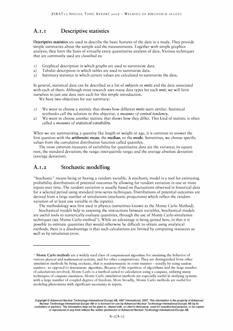
ZIRATr 2 SPECIAL TOPIC REPORT 2007 - WELDING OF ZIRCONIUM ALLOYS
A.I.I Descriptive statistics
Descriptive statistics are used to describe the basic features of the data in a study. They provide simple summaries about the sample and the measurements. Together with simple graphics analysis, they form the basis of virtually every quantitative analysis of data. Various techniques that are commonly used are classified as:
r ) Graphical description in which graphs are used to summarize data. 2) Tabular description in which tables are used to summarize data.
3) Summary statistics in which certain values are calculated to summarize the data.
In general, statistical data can be described as a list of subjects or units and the data associated with each of them. Although most research uses many data types for each unit, we will limit ourselves to just one data item each for this simple introduction.
We have two objectives for our summary:
r ) We want to choose a statistic that shows how different units seem similar. Statistical textbooks call the solution to this objective, a measure of central tendency.
2) We want to choose another statistic that shows how they differ. This kind of statistic is often called a measure of statistical variability.
When we are summarizing a quantity like length or weight or age, it is common to answer the first question with the arithmetic mean, the median, or the mode. Sometimes, we choose specific values from the cumulative distribution function called quantiles.
The most common measures of variability for quantitative data are the variance; its square root, the standard deviation; the range; interquartile range; and the average absolute deviation (average deviation).
A.I.2 Stochastic modelling
"Stochastic" means being or having a random variable. A stochastic model is a tool for estimating probability distributions of potential outcomes by allowing for random variation in one or more inputs over time. The random variation is usually based on fluctuations observed in historical data for a selected period using standard time-series techniques. Distributions of potential outcomes are derived from a large number of simulations (stochastic projections) which reflect the random variation of at least one variable in the input(s).
The methodology was first used in physics (sometimes known as the Monte Carlo Method). Stochastical models help in assessing the interactions between variables. Stochastical models
are useful tools to numerically evaluate quantities, through the use of Monte Carlo simulation techniques (see Monte Carlo method"). While an advantage is being gained here, in that it is possible to estimate quantities that would otherwise be difficult to obtain using analytical methods, there is a disadvantage is that such calculations are limited by computing resources as well as by simulation error.
33 Monte Carlo methods are a widely used class of computational algorithms for simulating the behavior of various physical and mathematical systems, and for other computations. They are distinguished from other simulation methods by being stochastic, that is nondeterministic in some manner - usually by using random
numbers- as opposed to deterministic algorithms. Because of the repetition of algorithms and the large number of calculations involved, Monte Carlo is a method suited to calculation using a computer, utilizing many techniques of computer simulation. Monte Carlo simulation methods are especially useful in studying systems with a large number of coupled degrees of freedom. More broadly, Monte Carlo methods are useful for modeling phenomena with significant uncertainty in inputs.
Copyright © Advanced Nuclear Technology International Europe AB, ANT International, 2007. This information is the property of Advanced
Nuclear Technology International Europe AB or is licensed for use by Advanced Nuclear Technology International Europe AB by its customers or partners. The information may not be given to, shared with, or cited to third party, used for unauthorised purpose, or be copied
or reproduced in any form without the written permission of Advanced Nuclear Technology International Europe AB.

ZIRA Tr 2 SPECIAL TOPIC REPORT 2007 - WELDING OF ZIRCONIUM ALLOYS
Appendix B - Fundamentals of metal welding (Peter Rudling)
B.l
B.Ll
Thermal and thermomechanical considerations of welding
Introduction
To interpret phenomena arising during the welding operation it is necessary to understand the thermal cycle of welding, i.e. the temperature variation 8 as a function of time t. The curve e =
f(t), plotted at point A close to a weld (Figure B-r) provides the following information:
• Maximum temperature reached, 8m, • Soaking time T" above a given temperature 8" • The cooling time TR(6J" 6)2) between two temperatures and 8, and 82 or cooling rate VR at the
temperature 8R•
Figure B-1:
e
I I I I I T----,.--I I I I I I
-�-----I-- -+--
I t I I t I : :: VR
-- l----�--l- -----------
I I I I t t t l I I I I i :: I
Parameters relative to the welding heat cycle e = f(Q at point A close to a weld, 6ln maximum temperature
reached; Ts( !9s), time above temperature !9s; TR(6)1 , eQ), cooling time between two temperatures e, and 8;.; VR
cooling rate at temperature 6R (slope of the tangent to the cooling curve), Granjon, 2002.
Copyright © Advanced Nuclear Technology International Europe AB, ANT Intemational, 2007. This information is the property of Advanced
Nuclear Technology International Europe AB or is licensed for use by Advanced Nuclear Technology International Europe AB by its customers or partners. The information may not be given to, shared with, or cited to third party, used for unauthorised purpose, or be copied
or reproduced in any form without the written permission of Advanced Nuclear Technology International Europe AB.
B-r(B-3 r)
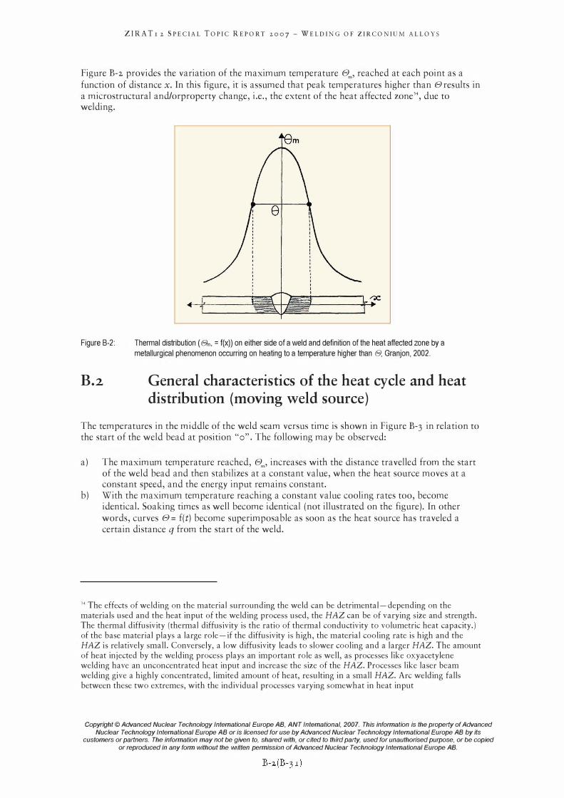
ZIRA Tr 2 SPECIAL TOPIC REPORT 2007 - WELDING OF ZIRCONIUM ALLOYS
Figure B-2 provides the variation of the maximum temperature 8m, reached at each point as a function of distance x. In this figure, it is assumed that peak temperatures higher than 8 results in a microstructural and/orproperty change, i.e., the extent of the heat affected zone'" due to welding.
Figure B-2:
B.2
Thermal distribution (a, = f(x)) on either side of a weld and definition of the heat affected zone by a
metallurgical phenomenon occurring on heating to a temperature higher than e, Granjon, 2002.
General characteristics of the heat cycle and heat distribution (moving weld source)
The temperatures in the middle of the weld seam versus time is shown in Figure B-3 in relation to the start of the weld bead at position "0". The following may be observed:
a) The maximum temperature reached, 8m, increases with the distance travelled from the start of the weld bead and then stabilizes at a constant value, when the heat source moves at a constant speed, and the energy input remains constant.
b) With the maximum temperature reaching a constant value cooling rates too, become identical. Soaking times as well become identical (not illustrated on the figure). In other words, curves 8 = f(t) become superimposable as soon as the heat source has traveled a certain distance q from the start of the weld.
J4 The effects of welding on the material surrounding the weld can be detrimental-depending on the materials used and the heat input of the welding process used, the HAZ can be of varying size and strength. The thermal diffusivity (thermal diffusivity is the ratio of thermal conductivity to volumetric heat capacity.) of the base material plays a large role-if the diffusivity is high, the material cooling rate is high and the HAZ is relatively small. Conversely, a low diffusivity leads to slower cooling and a larger HAZ. The amount of heat injected by the welding process plays an important role as well, as processes like oxyacetylene welding have an unconcentrated heat input and increase the size of the HAZ. Processes like laser beam welding give a highly concentrated, limited amount of heat, resulting in a small HAZ. Arc welding falls between these two extremes, with the individual processes varying somewhat in heat input
Copyright © Advanced Nuclear Technology International Europe AB, ANT Intemational, 2007. This information is the property of Advanced
Nuclear Technology International Europe AB or is licensed for use by Advanced Nuclear Technology International Europe AB by its customers or partners. The information may not be given to, shared with, or cited to third party, used for unauthorised purpose, or be copied
or reproduced in any form without the written permission of Advanced Nuclear Technology International Europe AB.
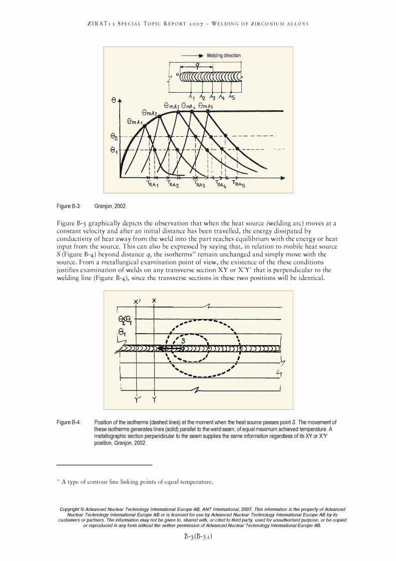
Figure B-3:
ZIRA Tr 2 SPECIAL TOPIC REPORT 2007 - WELDING OF ZIRCONIUM ALLOYS
e
Granjon, 2002.
--�.. Welding direction
f °tr!� A1 A2. A3 A+ AS
e rnAJ 8mA't ern As
Figure B-3 graphically depicts the observation that when the heat source (welding arc) moves at a constant velocity and after an initial distance has been travelled, the energy dissipated by conductivity of heat away from the weld into the part reaches equilibrium with the energy or heat input from the source. This can also be expressed by saying that, in relation to mobile heat source S (Figure B-4) beyond distance q, the isotherms35 remain unchanged and simply move with the source. From a metallurgical examination point of view, the existence of the these conditions justifies examination of welds on any transverse section XY or X'Y' that is perpendicular to the welding line (Figure B-4), since the transverse sections in these two positions will be identical.
Figure B-4:
I e�e1
181
�/J "!
l I ,
Xl )(
J�_
y' y
/'l
, ... - ... " ... ,
�, "
, " ... , , ( , , S -, ..
"::I�.].J.lJ!J_n 11) J r IY T Ii ' , " i , ... - .,
" , ....... ., " 0 -... - -- "
A i
Position of the isotherms (dashed lines) at the moment when the heat source passes point S. The movement of these isotherms generates lines (solid) parallel to the weld seam, of equal maximum achieved temperature. A metallographic section perpendicular to the seam supplies the same information regardless of its XY or X'Y' position, Granjon, 2002.
35 A type of contour line linking points of equal temperature.
Copyright © Advanced Nuclear Technology International Europe AB, ANT Intemational, 2007. This information is the property of Advanced
Nuclear Technology International Europe AB or is licensed for use by Advanced Nuclear Technology International Europe AB by its customers or partners. The information may not be given to, shared with, or cited to third party, used for unauthorised purpose, or be copied
or reproduced in any form without the written permission of Advanced Nuclear Technology International Europe AB.
ZIRATr 2 SPECIAL TOPIC REPORT 2007 - WELDING OF ZIRCONIUM ALLOYS
Appendix C - References
Abriata J. P and BolcichJ. c., Bull. Alloy Phase Diagrams 3(1),1982. Anderi P., "Vergleich von laser- mit elektronstrahlscheissen", Chem.-Ing.-Tech. 61, Nr. 10, pp.
767-774, 1989. Cheadle B.A and Aldridge S.A., "The transformation and age hyrdening behaviour of Zr-
I9wt%Nb", J. Nucl. Mat. 47, pp. 255-258, 1973· Dawes c., "Laser welding", Published by Abington Publishing, Abington Hall, Abington,
Cambridge CB I 6AH, England, 1992. Garzarolli F., Stehle H., Steinberg E.; and Weidinger H., "Progress in the Knowledge of
Nodular Corrosion", Zirconium in the Nuclear Industry, ih Int'l Symposium, ASTM STP 939, R. B. Adamson and L. F. P. Van Swam, Eds., ASTM, Philadelphia, 417-430, 1987.
Granjon H., "Fundamentals of welding metallurgy", Published by Abington Publishing, Cambridge CBl 6AH, England, 2002.
Kearns W. H., AWS Welding Handbook, American Welding Society, 1983. Kocher R. and Schmuck J., "Zirkonium, eigenschaften verarbeitung und anwendung in der
chemischen industrie", Mat.-wiss u. Werkstofftech. 21, pp. 407-430, 1990. Lancaster J., "Handbook of structural welding", Published by Abington Publishing, Abington
Hall, Abington, Cambridge CB I 6AH, England, First published 1992, Abington Publishing, Reprinted in paperback 1997.
Lucas W., "TIC and PLASMA Welding", Published by Abington Publishing, Abington Hall, Abington, Cambridge CB I 6AH, England, 1990.
Lustman B. and Kerze F., "Metallurgy of Zirconium", McGraw-Hill, New York, 1955. Ruge J., "Handbuch der Schwei(5technik", Springer Verlag, Hamburg Schultz H., "Electron beam welding", Published by Abington Publishing, Woodhead
publishing Limited, Abington Hall, Abington, Cambridge CBl 6AH, England, 2002. Shebaldov et aI., "EII0 Alloy cladding tube properties and their interrelation with alloy
structure phase condition and impurity content", ASTM STP 1354, pp. 545-559,2000. Zhang H. and Senkara J., "Resistance Welding", Published by CRC Press Taylor & Francis
Group, FL, USA, 2006.
Copyright © Advanced Nuclear Technology International Europe AB, ANT International, 2007. This information is the property of Advanced
Nuclear Technology International Europe AB or is licensed for use by Advanced Nuclear Technology International Europe AB by its customers or partners. The information may not be given to, shared with, or cited to third party, used for unauthorised purpose, or be copied
or reproduced in any form without the written permission of Advanced Nuclear Technology International Europe AB.
C-l(C-l)


