Welding and post weld heat treatment of 2.25%Cr-1%Mo steel
34
University of Wollongong Thesis Collections University of Wollongong Thesis Collection University of Wollongong Year Welding and post weld heat treatment of 2.25%Cr-1%Mo steel Benjamin King University of Wollongong King, Benjamin, Welding and post weld heat treatment of 2.25 This paper is posted at Research Online. http://ro.uow.edu.au/theses/479
Transcript of Welding and post weld heat treatment of 2.25%Cr-1%Mo steel

University of Wollongong Thesis Collections
University of Wollongong Thesis Collection
University of Wollongong Year
Welding and post weld heat treatment of
2.25%Cr-1%Mo steel
Benjamin KingUniversity of Wollongong
King, Benjamin, Welding and post weld heat treatment of 2.25This paper is posted at Research Online.
http://ro.uow.edu.au/theses/479

NOTE
This online version of the thesis may have different page formatting and pagination from the paper copy held in the University of Wollongong Library.
UNIVERSITY OF WOLLONGONG
COPYRIGHT WARNING
You may print or download ONE copy of this document for the purpose of your own research or study. The University does not authorise you to copy, communicate or otherwise make available electronically to any other person any copyright material contained on this site. You are reminded of the following: Copyright owners are entitled to take legal action against persons who infringe their copyright. A reproduction of material that is protected by copyright may be a copyright infringement. A court may impose penalties and award damages in relation to offences and infringements relating to copyright material. Higher penalties may apply, and higher damages may be awarded, for offences and infringements involving the conversion of material into digital or electronic form.

9
2.0 Literature review
2.1 2.25Cr-1Mo alloy steel
2.1.1 Alloy design
A typical analysis of 2.25Cr-1Mo steel is shown in Table 1, along with the ASME
SA335-P22 compositional tolerances [1,2]. The specific roles of the major alloy
additions are detailed below.
Table 1- Composition of 2.25Cr-1Mo alloy steel (wt %, single values max.) [1,2]
C Mn P S Si Cr Mo
Typical 0.15 0.50 0.011 0.013 0.25 2.30 1.00
P22 0.15 0.3-0.6 0.03 0.03 0.5 1.9-2.6 0.87-1.13
Chromium: The addition of Cr to this alloy provides oxidation resistance and
microstructural stability. Cr forms carbides within the grains, that anchor the
structure at high temperatures. Cr additions also significantly increase the
hardenability of the alloy, thus increasing as-welded strength. Cr in solution acts as a
ferrite former in steel and in higher concentrations raises the Ac3 transformation
temperature [3].
Molybdenum: The purpose of Mo in the alloy is to increase creep strength. The
substitutional Mo atoms increase the intrinsic matrix strength by solid solution
strengthening. Mo also improves the creep performance of the alloy through forming
Mo2C, as a coherent precipitate. This precipitate is credited with giving the greatest
contribution to creep performance in the Cr-Mo system [4] although it is not stable at
typical service temperatures. Mo in solution also causes an increase in the eutectoid
temperature and the Ac3 transformation temperature [5].

10
Carbon: Carbon is added to increase the strength of the material. Sufficient carbon
is also needed to form carbides with iron and the above alloying elements to provide
the precipitation strengthening and creep resistance. High levels of carbon however,
decrease weldability and for this reason 0.1-0.2wt% C is considered to be the
optimum range in terms of balancing creep strength and weldability [5].
2.1.2 Phase transformations
There are several phase transformations during the cooling of steel from the
liquid state to room temperature. One of the most important in welded plain carbon
steel, in terms of mechanical properties, is the solid-state transformation
γ → α + Fe3C. This transformation occurs as a eutectoid decomposition at 723 °C
(designated A1) under quasi-equilibrium conditions [6]. Pearlite is the name given to
the eutectoid mixture of lamellar α (ferrite) and Fe3C (cementite). As a result of the
hypoeutectoid C content of 2.25Cr-1Mo steel, proeutectoid ferrite is likely to form on
slow cooling from austenite, initiating at the Ar3 temperature.
The presence of the strong carbide formers Cr and Mo modify the composition
and structure of the carbide phase. The alloying elements also affect the temperature
at which phase transformations occur. The Ac1 transition temperature has been
quoted at 780 ºC in 2.25Cr-1Mo [7,8], and the Ac3 temperature at ~894 ºC [7] and
880 °C [8] with unspecified heating rates.
Under continuous cooling conditions such as those experienced during a weld
thermal cycle, the cooling rate determines the deviation from quasi-equilibrium and
therefore the morphology and extent of proeutectoid ferrite and carbide precipitation.
The products that form are metastable since they are produced under non-equilibrium
conditions.
With faster cooling, the distribution of the carbide phase will change, as will
the morphology of the ferrite. Austenite transforms to a bainitic type product at
moderately fast cooling rates. Bainite is a eutectoidal product of medium to high
11
carbon steel, which contains laths of ferrite with the carbide oriented along these lath
boundaries (upper bainite) or distributed within the ferrite laths (lower bainite).
Typically, multiple laths form together with a common orientation, forming a ‘sheaf’
or ‘packet’ [1]. The type of bainite formed depends on the transformation
temperature and therefore cooling rate.
Under isothermal transformation conditions upper bainite typically forms in
steel between 400 and 550 ºC and lower bainite between 250 and 400 ºC [6]. The
kinetics of the reactions are dependent on the composition of the steel.
The bainitic structures that form in low carbon steels are often described as
‘bainitic ferrite’ and ‘granular bainite’ [9]. These microstructures display bainitic
ferrite sheaves, without the carbides found in conventional bainite [1]. On continuous
cooling, the austenite transforms to bainite sheaves, rejecting carbon and enriching
and stabilising the remaining austenite in the process.
This enriched austenite does not transform to carbide as in the conventional
upper bainite reaction. Instead, the austenite is retained to low temperatures where it
may either remain in its metastable state or transform fully or partially to one of
several ‘residual phases’ [1,6]. Dunne identifies the possible residual phases as:
austenite, martensite, martensite-austenite constituent (MAC), high carbon bainite,
pearlite and degenerate pearlite [9]. Similarly, Bhadeshia describes the microstructure
after continuous cooling as predominantly bainitic ferrite with small regions or films
of retained austenite and/or high carbon martensite [1].
In 2.25Cr-1Mo, the bainitic product is likely to lie between the two extremes
of the conventional upper/lower bainite of high carbon steels and the bainitic
ferrite/granular bainite of low carbon steels. Due to a carbon level of 0.15% and the
presence of strong carbide formers, limited carbide precipitation is to be expected,
depending on cooling rate.
The alloying elements present in Cr-Mo steels and other low alloy grades
retard the ferrite and pearlite reactions and depress the start temperature of the bainite

12
reaction. This enables bainite to be formed through continuous cooling over a wider
range of cooling rates compared to plain carbon steel [6].
At yet faster cooling rates diffusionless transformation takes place to form a
supersaturated, distorted lattice known as martensite. This is a hard, brittle phase with
the same composition as the untransformed austenite. In steel with less than ~0.2% C,
the martensite forms supersaturated bcc laths. In steel with greater than ~0.2% C the
martensite phase has a body centred tetragonal (bct) structure and a plate morphology
[10].
The martensite transformation occurs athermally and is characterised by start
(Ms) and finish (Mf) temperatures, which depend on the alloy content [6]. The Ms
value for plain carbon steel with 0.15%C is quoted by Krauss as 460 °C [11]. Ms and
Mf values for 2.25Cr-1Mo have been quoted by Séférian [8] as approximately 250 °C
and 130 °C, values which are considerably lower than the Ms temperature reported by
Lundin, Kruse and Pendley [12] of about 400 °C. Andrews [13] developed the
following empirical formula for calculating the Ms temperature based on data from
steels with compositions up to 0.6% C, 5.4% Mo and 4.6% Cr.
Ms = (539 – 423C – 30.4Mn – 12.1Cr – 17.1Ni – 7.5Mo) °C Equation 1
This equation predicts an Ms temperature of 442°C for 2.25Cr-1Mo steel.
In the transformation of steels during cooling after welding, the most critical
region of the cooling regime in terms of property development has been found to be
between 800 and 500 ºC [11]. This is often recorded as the time taken to cool
between these two temperatures (t 8-5) under continuous cooling conditions.
To describe the various transformations that occur in a particular alloy,
transformations can be plotted with respect to time and temperature. A continuous
cooling transformation (CCT) diagram is most relevant to studies of welded
structures. A CCT diagram for 2.25Cr-1Mo from Séférian [8] is shown in Figure 1
and one from Lundin, Kruse and Pendley [12] in Figure 2.

13
Figure 1- CCT diagram for 2.25Cr-1Mo from Séférian [8]
Figure 2 – CCT diagram from Lundin, Kruse and Pendley [12] taken from [1].
14
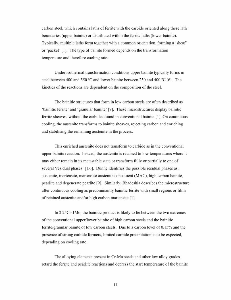
2.1.3 Tempering
The metastable phases described above will transform to more stable
structures with the provision of thermal energy. The microstructure developed on
tempering will approach the equilibrium structure. This process of transforming a
quenched material by heating, in order to increase toughness, is known as tempering
[11].
The type and morphology of the phases produced by tempering depends on the
initial microstructure and the tempering conditions. The microstructure and property
response to tempering of martensite and bainite are therefore different. The rate of
this transformation is also dependent on the temperature at which the tempering
occurs.
The martensite structure tempers quickly, as the supersaturation of the matrix
structure provides significant driving force. The initial structure shows a very fine
dispersion of carbides precipitated in a ferritic matrix. This tempered martensite
exhibits a decrease in hardness coinciding with an increase in toughness. The
precipitated carbides then continue to coarsen with subsequent tempering, resulting in
a further decrease in hardness.
The bainite structure already contains some carbide precipitation, therefore the
matrix contains significantly less supersaturated carbon and there is a lower driving
force for carbide precipitation. The initial size of the carbide particles is large
compared to the precipitates in martensite, and hence they coarsen more slowly. The
result of these microstructural differences is that the bainite shows a less rapid
decrease in hardness with tempering.
2.1.4 Transitional phases
The precipitated carbide (if any) present on rapid cooling of 2.25Cr-1Mo is the
transitional carbide structure known as ε-carbide [14], which is precipitated from the
high cooling rate transformation products (bainite and martensite). The structure of

15
this carbide differs from the quasi-equilibrium cementite by having a higher carbon
content (Fe2.4C as opposed to Fe3C). This carbide also exhibits a different crystal
structure, more compatible with the metastable martensite structure [11]. A similar
transitional carbide, η-carbide has also been described in other steels, forming in
conjunction with ε-carbide [11].
The decomposition of these carbides to the more stable cementite phase can
also involve another intermediate carbide phase, χ-carbide. This phase has the
composition Fe5C2 and has been resolved preceding the formation of cementite (or θ-
carbide). These transitional Fe-carbides are replaced by even more stable alloy
carbides within short times at elevated temperatures, such as in PWHT or as seen in
thermal power plant service.
The transient alloy carbide structures observed in 2.25Cr-1Mo alloy steel are
discussed in Section 2.3.1 below.
2.2 Welding Characteristics of 2.25Cr-1Mo
2.2.1 Fusion Welding
Several techniques have been developed to manipulate an electric discharge
arc to provide localised heating, melting and solidification of material to form a bond
between components. The most commonly used techniques in the fabrication of Cr-
Mo high temperature systems are discussed below.
Manual Metal Arc Welding (MMAW): This technique involves an electrode wire
sustaining an arc with the workpiece. The arc then melts the electrode and its flux
coating to form the weld pool and shielding slag and gases. This technique is the
most widely used for welding 2.25Cr-1Mo [15]. Figure 3 is a diagrammatical
representation of MMAW.

16
Figure 3- Manual Metal Arc Welding
Gas Tungsten Arc Welding (GTAW): For this process, the arc is made between the
workpiece and a fixed electrode (usually made of tungsten). The filler material is
supplied in the form of a rod introduced to the vicinity of the arc. The shielding is
supplied as an inert gas through a nozzle around the electrode. This process finds use
in welding thin sections of 2.25Cr-1Mo or in welding a root run before filling by
MMAW [16].
Submerged Arc Welding (SAW): This process utilises an arc maintained between
the workpiece and a consumable wire electrode. The shielding for the weld pool is
provided by granulated flux material fed onto the weld pool from a hopper. This
process is particularly suitable for mechanisation, but is limited to horizontal welding
applications [17].
The differences between the techniques are based on how the arc is formed
and how the weld pool is shielded from the atmosphere; which in turn influence the
amount of heat applied to the workpiece and how effectively the weld pool can be
controlled. These parameters influence cooling rate and inclusion concentration.

17
In addition to these metallurgical effects, practical considerations such as
portability, ease of operation in positional welding and level of operator skill required
dictate which technique is most suitable for a given application.
2.2.2 Welding metallurgy
During the fusion welding process, heat is delivered to the workpiece through
the welding arc. This produces a region of material subject to elevated temperatures
adjacent to the weld bead. Material in this region will be heated through a maximum
temperature, which depends on its distance from the fusion line. This maximum or
‘peak’ temperature, along with the subsequent cooling rate, determines the structure
of the HAZ of the weldment.
The peak temperature is dependent on the relative values of the heat input
from the welding arc and the ability of the material to conduct away this heat. This
results in the peak temperature being a function of the distance from the weld fusion
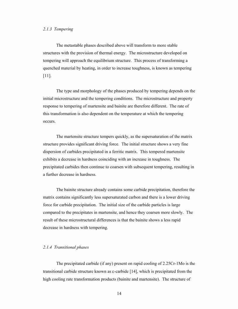
line. Several zones with common microstructural features have been identified and
are shown in Figure 4. These zones are described below in order of increasing
distance from the line of fusion:
Weld metal: This term refers to that material which was completely melted by the
welding process and subsequently solidified. It is supplied by the welding
consumables and/or the workpiece itself and forms the weld bead.
Coarse Grained Heat Affected Zone: Since the temperature of the liquid weld
metal deposit is well above the austenite transformation temperature (Ac3 ~894 ºC for
2.25Cr-1Mo [7]), the base material adjacent to the weld metal will be heated into the
austenite phase field. Material close enough to the weld will have sufficient heat and
time at temperature to totally transform to austenite.
Depending on the heat input of the welding process and the alloy, a degree of
austenitic grain growth will also occur depending on the thermal conduction kinetics.

18
For 2.25Cr-1Mo, the stabilising carbides dissolve on heating in the temperature range
1000-1050 ºC [7] allowing significant austenite grain growth in areas with a peak
temperature above these values. This region is called the Coarse Grained Heat
Affected Zone (CGHAZ).
Fine Grained Heat Affected Zone: This zone appears adjacent to the CGHAZ
region, where the austenitic transformation also occurs, but without any substantial
grain growth. As a result the austenite grains are refined and thus on transformation
produce a refined ferritic region: the Fine Grained Heat Affected Zone (FGHAZ).
Intercritical Zone: At a distance still further from the line of fusion, the material
receives only enough heating to partially transform to austenite. This region is called
the Intercritical Zone or the Type IV region.
Tempered Zone: For still lower peak temperatures, a zone exists where no material
transforms to austenite, but the temperature experienced can still be sufficient to cause
changes in base material structure. Grain growth, second phase morphology changes
and precipitate coarsening can all occur in the tempered zone.
The sum of the above zones is referred to as the weldment. Any material lying
outside these zones has not been directly affected by the welding process and is
therefore not part of the weldment. While not directly affected by the welding
process, an indirect effect such as a residual stress field could extend into the parent
material.
The above regions are described as formed from the deposition of a single
weld bead. When welding heavy sections, many weld beads will have to be made on
top of one another in order to produce the required volume of fill. This produces a
multi-pass weld with a composite HAZ as subsequent runs can partially melt and
reheat previously heat affected material. Weld metal is also reheated above the
critical values, thus forming a weld metal HAZ in addition to the parent metal HAZ.
A study by Li et al [16] found that about 50% of the parent metal HAZ had
austenitised or partially austenitised a second time in subsequent runs of a multi-pass
weld of 0.5Cr-0.5Mo-0.25V steel.
19
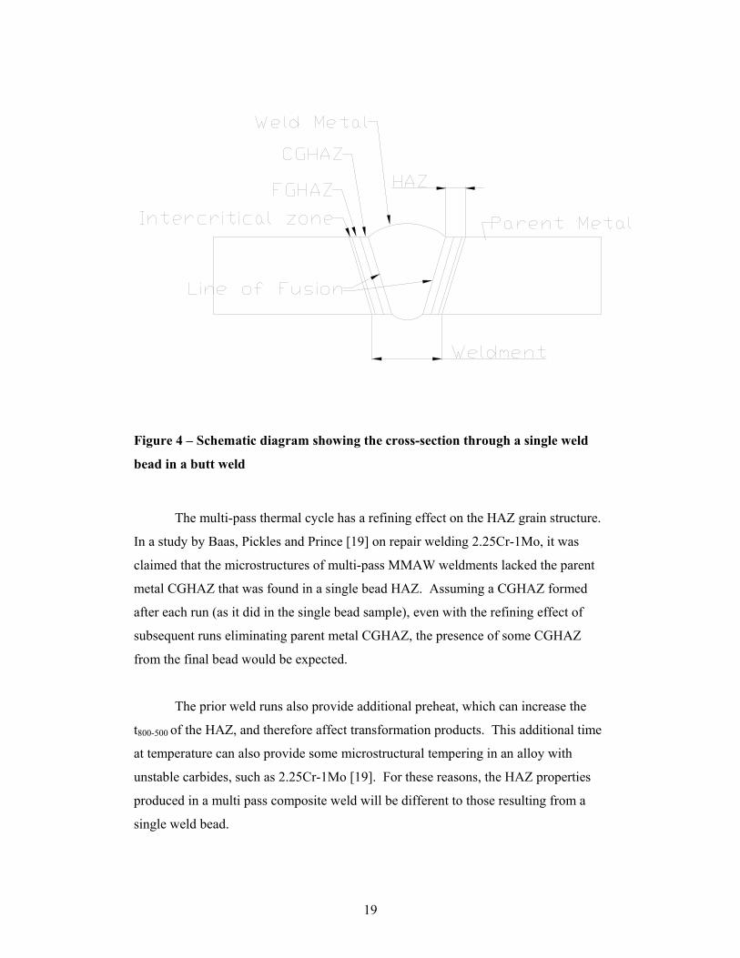
Figure 4 – Schematic diagram showing the cross-section through a single weld
bead in a butt weld
The multi-pass thermal cycle has a refining effect on the HAZ grain structure.
In a study by Baas, Pickles and Prince [19] on repair welding 2.25Cr-1Mo, it was
claimed that the microstructures of multi-pass MMAW weldments lacked the parent
metal CGHAZ that was found in a single bead HAZ. Assuming a CGHAZ formed
after each run (as it did in the single bead sample), even with the refining effect of
subsequent runs eliminating parent metal CGHAZ, the presence of some CGHAZ
from the final bead would be expected.
The prior weld runs also provide additional preheat, which can increase the
t800-500 of the HAZ, and therefore affect transformation products. This additional time
at temperature can also provide some microstructural tempering in an alloy with
unstable carbides, such as 2.25Cr-1Mo [19]. For these reasons, the HAZ properties
produced in a multi pass composite weld will be different to those resulting from a
single weld bead.

20
2.2.3 Thermal effects of welding
The thermal conditions produced by the process of fusion welding are, by its
nature both transient and highly localised. The maximum temperature of the welding
arc in contact with the material has been estimated between 3000 – 4000 °C [20].
When applied to a component at ambient temperature (or even pre-heated to several
hundred degrees C) extremely high thermal gradients are produced. Moreover, since
the heat source is moving over the surface of the component, there is insufficient time
to reach a steady state of heat flow.
Many factors influence the development of the heating and cooling cycles
experienced by a welded component. The welding operation delivers both heat and
liquid metal to the component which subsequently cools through a combination of
processes: radiation to the surroundings; heat conduction into the parent metal; forced
convection due to any shielding gas flow and natural convection at the surface after
the weld pass. The weld metal also provides a further source of heat as the latent heat
of fusion is evolved during solidification.
The description of the processes occurring in the weld metal has been the
subject of significant study [21, 22, 23]. Material and process parameters such as
electromagnetic forces, surface tension effects, arc pressure, convection within the
pool, and the method of material transfer all influence the thermal profile and
resultant geometry of the weld bead [20].
The effect of welding on the HAZ is to rapidly raise the temperature to
approach its melting point in the CGHAZ. This heat is supplied to the HAZ, initially
by the arc and subsequently the cooling weld metal. The rate at which heat is
conducted into the surrounding parent material depends on the geometry and material
properties of the component.
The extent and magnitude of microstructural development in the HAZ in turn
depends on this thermal cycle. The HAZ thermal cycle is composed of two regions, a
heating component as the arc approaches and a cooling component as the arc recedes.

21
The two most significant features of this heating cycle, as determined by their effect
on the resultant material properties are the peak temperature and the cooling rate [24].
Attempts have been made to determine weld thermal cycles analytically by
describing the thermal field produced. The most common solutions involve
simplifying assumptions and methods of solving the basic equation of heat conduction
through a solid, which has the form shown in Equation 2 for the rectangular co-
ordinates shown in Figure 1. This equation assumes temperature-independent
material property values.
∂∂
+∂∂
+∂∂
=∂∂
2
2
2
2
2
2
zT
yT
xT
ctT
ρλ Equation 2
Where λ = material thermal conductivity
T = temperature
t = time
c = mass specific heat capacity
ρ = material density
Figure 5 – Co-ordinate system applied to heat source moving over a plate in the
positive x-direction
xy
z

22
To solve this equation for a welding process the geometry of both the
component and the heat source need to be considered (and simplified). Rosenthal
[25] provides solutions for this equation in infinite and semi-infinite solids assuming
point and line heat sources. Rosenthal’s analysis, when applied to welding showed
two distinct modes of heat conduction possible in butt-welding plates; 2-dimensional
heat flow and 3-dimensional heat flow. These modes corresponded to heat
conduction in ‘thin’ and ‘thick’ plates respectively. Comparison of experiment and
calculation showed that plates above approximately 36 mm behave as “thick” plates
[25].
This definition of ‘thin’ plates refers to those conditions where there is no
temperature gradient in the z-direction, corresponding to the physical situation where
the plate in question has a z-dimension no larger than the heat source (weld bead) or
there has been sufficient heat conduction to give a constant temperature in the z-
direction. A ‘thick’ plate is one with unrestricted conduction in the positive z-
direction, corresponding to a plate which is thick enough in the z-direction that the
bottom surface does not experience any heating. It can thus be reasoned that any real
plate thicker than one weld bead will cool by a combination of these thin/thick plate
extremes.
Ashby and Easterling [24] summarised the analysis of Rosenthal into
equations relating temperature outside the fusion zone to time in both conduction
modes. The solution to Equation 2 in the 3-dimensional conduction condition (thick
plate) is:
−+=
atr
tvqTT
4exp
2
2
0 πλ Equation 3

23
The thin plate approximation is given by:
−+=
atr
ctdvqTT
4exp
4
2
0 πλρ Equation 4
Where: 0T = pre-heat temperature ( K )
q = arc power ( J s-1 )
v = arc speed (m s-1 )
d = plate thickness ( m )
r = distance from weld ( m )
a = cρλ = thermal diffusivity (m2s-1 )
Rosenthal’s solutions have been compared with experimentally observed
thermal fields due to arc welding by Miranda and Fortes [26] and Kuo [27]. These
studies observed a fair level of correlation between calculated values and measured
data.
Ashby and Easterling showed further manipulation of the above equations
gives Equation 5, which is a solution for the time to cool between 800 °C and 500 °C
(∆t) within a thick plate cooling regime. Note that ∆t is independent of the distance
from the weld bead.
12/
πλθvqt =∆ Equation 5
Where:
−−
−=
001 10731
77311
TTθ
λ = thermal conductivity (Js-1m-1K-1)

24
Rosenthal’s analysis also included application to actual welding processes and
thus resolving the thermal cycle in plates between the limits of ‘thick’ and ‘thin’
behavior. All plates more than one weld bead in thickness will initially conduct in 3-
dimensions. At the point where the conduction in the z-direction is interrupted by the
bottom surface, the conduction mode changes not to 2-dimensional conduction but to
a non-isotropic 3-dimensional conduction mechanism. This restriction of heat flow in
the z-direction due to the surface of the plate can continue to increase until the thermal
gradient in the z-direction has been reduced to zero, where the conduction mode
changes to 2-dimensional. The deviation from thick plate behavior is described by
Rosenthal [25] through the introduction of a coefficient to modify the cooling time
value calculated from the thick plate approximation equation, as shown in Equation 6.
°
⋅⋅=−t
Jk
IFTT 120 νπ
Equation 6
where:
k = cρ / 2λ
µtt =°
t° = cooling time calculated from thick plate approximation
t = actual cooling time
∑−−
+=n
n
S
Ste )1(21
2λνµ
( )vtndvt
Sn)2()( 22 +
= , n = 1,2,3….
IF = input factor, or the proportion of supplied heat that enters the work piece

25
Through differentiation and substitution of Equation 6, Rosenthal gave the
following relation for the cooling rate:
µµ′−
−=tTT
dtdT 0 Equation 7
Where:
[ ]1)1(21 22
)1(2
−−−=′ ∑−−
nnn
nSt
SStS
e λνµλν
This analysis of the cooling of plates of intermediate thickness was compared
by Rosenthal to the experimental results of Hess et al [28]. The author claims the
agreement to be good enough for practical purposes on the basis of errors of less than
5% within the temperature range 700 °C to 300 °C.
2.2.4 Microstructure of 2.25Cr-1Mo weldment
‘Matching’ consumables are typically used when welding 2.25Cr-1Mo, such
as the low hydrogen AS1553.2:1999- E6215-B3L coated electrode, with the
composition limits shown in Table 2 [29]. It can be seen that although the electrodes
are termed matching, there are significant differences between the levels of C, Mn and
Si compared to the plate specification in Table 1. Therefore, some dilution effects
could be expected particularly around the line of fusion.
Table 2- Composition limits for low-hydrogen, matching covered electrode
C S Mn Si Cr Mo P
E6215-B3 0.05 0.03 0.9 1.00 2-2.5 0.9-1.2 0.03

26
Andrén, Guanjun and Svensson investigated the weld metal structure in a
2.25Cr-1Mo weldment [30]. This study used TEM analysis to identify a structure of
bainitic ferrite and retained austenite devoid of carbide precipitates. This structure
was given the title ‘granular bainite’, in line with the classification of a quoted study
by Harbraken and Economopoulos [31]
The 2.25Cr-1Mo HAZ structure adjacent to the line of fusion in a multi-pass
weld has been described as predominately ‘tempered bainite’ by Baas, Pickles and
Prince [19]. This study found the structure to contain ‘relatively large bainitic
packets’, some small ferritic zones and tempered martensite. Further away from the
line of fusion in the intercritical region, the structure was found to be untransformed
ferrite and tempered martensite. Other work by Peddle and Pickles [7] describes the
microstructure of the HAZ after a typical weld cycle as lower bainite with some
martensite.
The microstructure of normalised and tempered base material shows ferrite
and bainite with precipitates of ε-carbide or cementite in the bainitic regions [14].
Typical structures consist of ~70% bainite and ~30% ferrite [7].
2.2.5 Residual stress
The cooling of a localised volume of material from its melting point to
ambient temperature involves a significant reduction in volume. Since the weldment
structure remains continuous, there must be a mechanism whereby this difference in
strain is accommodated. This is achieved in part through plastic strain of the material.
The balance is accommodated through elastic strain. This results in a stress field
distributed throughout the material after cooling, known as residual stress.
In welds of thick sections, the residual stresses that develop in the weldment
often exceed the yield strength of the material. Therefore, the material yields and the
remaining residual stress can be at the level of the yield stress, as the full elastic strain
limit has been reached [17].

27
In a multi-pass weld the residual stress field produced is triaxial [32]. Since
the weld metal is sufficiently constrained by the parent metal in each principal
direction, the residual stresses also act in these three directions. This residual stress
field can considerably decrease the strength of a weldment.
2.2.6 Secondary hardening
Secondary hardening describes the phenomenon of an increase in hardness of
an alloy steel during the process of tempering. The mechanism for this hardening is
the formation of coherent or semi-coherent precipitates within the structure, providing
precipitation strengthening. Alloy steels such as 2.25Cr-1Mo precipitate both Fe and
alloy based carbides.
The diffusion kinetics of the substitutional alloy species preclude them from
forming the more stable alloy carbides in the time frame of a welding thermal cycle.
In 2.25Cr-1Mo, quenched structures may or may not have precipitated Fe-carbides but
are still supersaturated with respect to the alloy species. Further thermal activation
will allow the diffusion and precipitation of these more thermodynamically stable
alloy carbides.
Studies have shown that 2.25Cr-1Mo alloy is capable of secondary hardening
after MMAW welding [7,19]. The rate of secondary hardening is related to the
mobility of carbide forming elements and therefore the temperature of tempering.
Quenching the alloy results in a supersaturation of Cr and Mo in the matrix.
Precipitation of alloy carbides upon further heating relieves this supersaturation. The
alloy carbide structure formed is initially relatively fine and thus can increase
hardness provided the heat treatment does not simultaneously temper and decrease the
effect of the other strengthening mechanisms.
The secondary hardening mechanism in rapidly cooled 2.25Cr-1Mo steel has
been attributed to the precipitation of fine Mo2C [5,19]. This hardening peak is
reached after approximately 1 h in the common service temperature range

28
(538-566 °C) and resoftening has been observed within 100 h [19]. These particles
initially precipitate as acicular, elongated needles [19].
Subsequent time at temperature sees the hardness decrease at a steady rate.
This softening is attributed to the coarsening and spheroidising of the Mo2C needles
and an increase in alloy content within the carbide particles.
2.2.7 Stress relief cracking
This form of cracking occurs as a weldment is reheated either in service or as
part of a Post Weld Heat Treatment [33]. For this reason it is also referred to as reheat
cracking. The cracking primarily occurs in the HAZ and is intergranular with respect
to the prior austenite grain boundaries.
There are two forms of stress relief cracking, operating at different
temperatures. The higher temperature process involves fracture due to microvoid
coalescence. This mechanism is initiated by the presence of particles at grain
boundaries. These can be compounds of contaminant species or of alloying elements
such as carbides.
These particles can decohere from the matrix, effectively causing a
discontinuity or void in the matrix. The composition of these particles influences the
cohesive strength at the matrix/particle interface. This cracking mechanism is
sometimes referred to as embrittlement and can occur after long periods of service or
after secondary thermal treatments.
The second, lower temperature form of stress relief cracking is characterised
by low-ductility intergranular cracking. The mechanism for this form of crack
development is related to the relative strengths of the grains and grain boundaries.
The precipitation of a particle dispersion within the bulk grain structure gives an alloy
increased strength. Grain boundaries act as favoured nucleation and growth regions
and can contain coarsened carbides surrounded by precipitate free zones (PFZ). As

29
such, the grain boundary regions are less effectively strengthened by the precipitates
and therefore weaker.
This strength difference within a grain causes localised strain to build up at
grain boundaries and the nucleation of cracks when exposed to certain loading and
thermal conditions. The initiation of this cracking is dependant on the existence of a
triaxial stress state. Such a stress state is observed in the residual stress fields of
welded joints as discussed above.
Stress relief cracking by both mechanisms has been reported for the 2.25Cr-
1Mo alloy system [34, 35, 36]. The effect of various levels and types of impurity
species have also been investigated in these studies, with sulphur, tin and phosphorus
all aiding in these low-ductility fractures. There is also a synergistic effect when
several species are present, such as in older, low purity Cr-Mo commercial alloys
[34].
Investigations into the propensity for stress relief cracking have been
performed on more modern, higher purity 2.25Cr-1Mo by De Witte and Coussement
[37]. This study found the alloy exhibited a ‘ductility dip’ at temperatures around
650 ºC. However, the conclusion was reached that this alloy did not require any
special precautions during welding to avoid reheat cracking.
2.2.8 Hydrogen cracking
This form of cracking, also referred to as cold cracking occurs after cooling of
the weldment. The welding process invariably introduces dissolved hydrogen into the
weldment structure [17]. Several mechanisms by which this dissolved hydrogen leads
to cracking have been proposed, without widespread agreement on the most likely
mechanism [38].
Hydrogen cracking often involves a significant incubation period before the
cracking is either detected or causes the component to fail. This incubation period is
30
associated with the diffusion of hydrogen and can be of the order of several weeks
[17].
The cracking proceeds in a step-wise fashion typically in the HAZ. There is a
strong dependence on notch intensity to initiate the cracking. Such stress
concentration in a weldment is usually supplied by the geometry of the weld toe. Any
defects included in the weld structure such as slag, pores etc could also contribute to
stress concentration.
While the exact mechanism involved in hydrogen cracking is subject to
conjecture, the factors which contribute to its appearance are widely accepted [17].
The most significant of these factors are:
- Hydrogen content
- Residual stress
- Microstructure.
The most common region for hydrogen crack initiation is the CGHAZ. The
increased size of prior austenite grains increases the segregation at grain boundaries
[17]. It would appear that the role of hydrogen in the cold cracking mechanism is to
decohere the matrix-particle interfaces of both precipitates and inclusions [39].
For a microstructure to be so considered ‘susceptible’, it should exhibit the
following properties [17]:
- Relatively hard grains (martensite or bainite)
- Coarse prior austenite grain size
- Grain boundary particles (Carbide precipitates or slag inclusions)
- High dislocation density
The properties of 2.25Cr-1Mo weldments (hardenable, dispersion strengthened)
render it susceptible to hydrogen cracking and for this reason, most weld procedures
require the use of low hydrogen electrodes and thermal treatments to encourage H
effusion.

31
2.3 Service Characteristics of 2.25Cr-1Mo
2.3.1 The effect of service conditions on microstructure
The alloy content of this grade of steel exceeds the solubility limit of the bcc
matrix phase and therefore 2.25Cr-1Mo is a multi-phase material under equilibrium
conditions. The excess alloy content exists in the form of carbides distributed
throughout the ferrite matrix. The alloy carbides can dissolve significant amounts of
other alloying elements to form non-stoichiometric alloy carbide phases.
When heated to service temperatures, the carbides will change composition
and morphology to approach equilibrium within the service life. The stable phase
eventually reached is dependent on several factors, such as initial structure and
compositional segregation. Studies have shown that after the typical service cycle of
this material the carbides are of the M6C or M23C6 type [5,14,40] where the M
symbolises the sum of all metallic species in the carbide.
The progression towards the stable carbide structure involves several steps
through intermediate carbide phases. Early work by Baker and Nutting [14] proposed
the following sequence of carbide precipitation, by observing the tempering response
in both normalized and quenched material:
Figure 6- Carbide progression map for both quenched and bainitic regions of
normalized structures tempered for times up to 1000 h in the temperature range
400-750 °C (from Baker and Nutting [12] ).
32
More recent experimentation by Tsai and Yang [40] agreed with this general
sequence but failed to observe M6C and named the final product of the carbide
progression as M23C6. In contrast, Williams [41] describes M6C as intermediate to the
formation of M23C6. This result is contrary to the trend of the carbides progressing
towards structures with a higher metal content. The properties and precipitation
mechanisms of these carbides are summarised below:
M3C : This carbide is initially formed as Fe3C, and can dissolve other alloy
constituents such as Cr to replace up to around 20% of the initial Fe [42]. Mo can
also be accommodated in the carbide structure but only up to approximately 4% [5].
Apart from ε-carbide M3C is the least thermodynamically stable of the carbides, it is
quickly replaced by higher alloy carbides during heating [14, 43].
M2C : This carbide is based on Mo2C and can dissolve significant amounts of Cr (up
to 30% of its weight [5]). It can be precipitated from both the quenched and
normalised structure [14]. This carbide is found to precipitate by intragranular
nucleation directly from the ferrite. Initially, Mo2C is thought to be coherent with the
matrix, before developing into needle-shaped, non-coherent precipitates [5, 42, 44,
45].
M7C3 : This carbide is based on the Cr7C3 structure and is capable of dissolving
significant amounts of Fe[46]. The precipitation of this carbide occurs in the vicinity
of the existing Fe3C [5], nucleating at ferrite/Fe3C interfaces [45]. Through studies of
Cr-C alloys, the Cr7C3 carbide was shown to precipitate and coarsen much faster than
other alloy carbides and as a result is not expected to produce significant secondary
hardening [45].
M23C6 : This carbide is thought to be based on either Cr23C6 or Fe21Mo2C6. The
precipitation of this phase occurs at the expense of existing Fe3C and Mo2C. Baker
and Nutting [14] showed it was only developed in quenched structures or bainitic
areas of this alloy. It does not require the dissolution of Cr7C3 and also is not
observed in areas of existing Cr7C3 [5]. This carbide nucleates and grows as plate-like
particles [41].
33
M6C : This carbide has been described as Fe3Mo3C by Qu and Kuo [47] and as
varying between Fe3Mo3C and Fe4Mo2C by Olsen and North [5]. The structure is also
capable of dissolving significant amounts of Cr [5]. This is the most alloyed of the
carbides observed in this system and has been reported to be the end product of the
carbide reaction path outlined above by several studies [14, 41, 43]. It forms as large
faceted particles at grain boundaries [5,43]. Baker and Nutting [14] showed this
carbide to form in both the bainite and ferrite of a normalised structure. M6C is
thought to provide less dispersion strengthening than other carbides [43].
Research by Williams [41] showed that the M23C6, M6C and a M7C3 phases
can all exist simultaneously in the same alloy sample. Different grains can progress
along the carbide evolution path at different rates due to small-scale heterogeneity.
The rate of degradation and the morphology of the precipitated and re-
precipitated carbides show a complex response to temperature and initial
microstructure. Since the carbide development is dependant on the initial
microstructure, a heterogeneous microstructure such as a weldment will exhibit a
variety of carbide distributions throughout its different zones.
In summary, the dispersed carbide phases in a 2.25Cr-1Mo alloy are
metastable in both the as-welded and normalised (parent metal) conditions [14, 48],
and will change progressively towards more stable forms under thermal activation.
2.3.2 Creep failure
Creep is the plastic flow of a material under constant load or stress over a
prolonged period [49]. Significant deformation is typically only observed at high
temperature. This ‘high’ temperature where creep mechanisms become significant is
said to be approximately 0.3-0.4 Tm [50]. The stress and temperature affect the rate
and dominant mechanisms of creep [51]. The typical service operating temperature
and pressure of 2.25Cr-1Mo pressure vessel components (~550 ºC and ~3 MPa [15])
enables creep under service conditions.

34
Creep curves (strain- ε verses time- t) show a general shape displaying three
different regions, which have been termed primary, secondary (or steady-state) and
tertiary [50]. Primary creep occurs rapidly and the high initial creep rate decreases to
a steady rate. The material then continues to creep linearly at this rate, which is the
secondary creep or steady-state region. At the onset of tertiary creep, voids form in
the structure and the creep rate increases until failure. The increasing creep rate
ascribed to tertiary creep is due to the decrease in cross section and associated
increase in stress [52].
In addition to the creep processes modifying the structure of the material, the
high temperature also causes changes to its heat-treated state. As the material ages at
temperature and the carbides develop as outlined above, the nature and strength of the
dispersion strengthening changes. As coarse alloy carbides form at grain boundaries,
alloying elements are depleted in the adjoining material and precipitate free zones
(PFZs) develop [43].
These regions, without the dispersion strengthening from the carbides, display
different mechanical properties to the bulk material. The depletion of solid solution
strengthening elements such as Mo through the formation of these precipitates also
changes the strength of the matrix. Qu and Kuo [47] found levels of Mo in solution
within ferrite decreased to ~55% of their original values after 64,000 h at a service
temperature of 540 °C. Similarly, Biss [53] found that the 96% of Mo which was
originally in solution decreased to 32% of Mo in solution after service.
The presence of grain boundary carbides can also facilitate low ductility
fracture. The carbide/matrix interface can de-cohere and act as a nucleation site for
cavitation. The growth and coalescence of these cavities can cause premature failure
with limited macroscopic ductility.
Sulphide particles have been identified as playing a significant role in
decohesion and cavitation of creeping material [54]. The stability of sulphide-
containing particles (commonly MnS) has a strong influence on particle-matrix
cohesion. The stability of sulphide particles is increased by the presence of Cr in the
35
matrix. As the carbide evolution progresses, Cr is removed from solution and the
interface of the sulphide particles becomes unstable, thus increasing the propensity for
decohesion.
Similar embrittling effects are observed at the grain boundaries with the
introduction of other trace elements, particularly P and Sn. Trace elements such as
these, inevitable remnants of the steel-making process, have been shown to segregate
to the grain boundaries and embrittle the structure during service [48, 55]. A similar
mechanism has been studied in reference to the time frames typical of stress relief
cracking as discussed above [34, 35]. The level of impurities necessary to cause
significant embrittlement has been shown by Wada [56] to be greater than 33 ppm.
A weldment structure is particularly susceptible to creep failure and the
majority of service failures in 2.25Cr-1Mo have been due to creep failure in a
weldment [57]. This susceptibility is due to both diminished creep properties and the
constraint associated with the heterogeneous material [58].
The most susceptible region of the weldment occurs in the HAZ [54] or more
specifically at the boundary between the fine grained HAZ and the intercritical zone
[57]. This region is also known as the Type IV region. The temperature attained in
this region during welding ensures coarsening of the carbide structure without
sufficient time at temperature to redissolve into the austenite. The microstructure on
cooling then consists of fine-grained ferrite and coarsened carbides.
This initial structure is susceptible to creep damage during subsequent service
because the weakened region is susceptible to localised deformation. This can result
in severe local creep deformation in the small weakened zone, which may appear as a
brittle failure when measured with respect to strain of the whole component [57].
2.3.3 Current welding practice:- Post Weld Heat Treatment
Post weld heat treatment (PWHT) is a technique for improving the properties
of weldments by subjecting them to a homogenising heat treatment. This process can
be used to reduce the susceptibility to hydrogen and reheat cracking and also

36
manipulate mechanical properties through tempering. Current Australian and
international practice is to specify PWHT for the majority of 2.25Cr-1Mo
fabrications.
PWHT is specified in this grade of steel to reduce the effect of residual stress
and to soften the structure. The internal stresses are relieved through thermally
activated processes such as dislocation climb. For this reason, PWHT is also referred
to as stress relief heat treatment.
The PWHT operation in 2.25Cr-1Mo improves the material toughness by
removing the potential for secondary hardening in service. It does so by over-aging
the material by precipitating the secondary alloy carbides and rapidly coarsening them
to drive the precipitation beyond the secondary hardening peak. In this way, the
weldment will be able to go into service without the risk of becoming brittle due to
excessive precipitation hardening.
Creep properties are also improved by homogenising the weldment and
minimising the potential for localised deformation. This reduces the detrimental
effect of strain accumulation at a weak zone such as the Type IV HAZ region.
Australian Standard 4458:1997 – Pressure equipment- Manufacture, specifies
that 2.25Cr-1Mo should undergo a PWHT in the range 680-750 °C. This temperature
range is further constricted to 680-730 ºC where creep resistance is required or 710-
750 °C for optimum corrosion resistance [60]. This specification applies to all
sections of pipe greater than 12 mm thick or with an outer diameter greater than 127
mm. The PWHT temperature must be maintained for 1 h / 25 mm of component
thickness. This soak period is limited to a minimum of 2 h and a maximum of 6 h.
International welding standards also utilise PWHT in the welding of 2.25Cr-
1Mo. The ASME Boiler and Pressure Vessel Code [61] requires a PWHT of 725 °C
for 3 h. This treatment is specified for all sizes of 2.25Cr-1Mo. In their survey of the
United States power generation industry, Viswanathan and Gandy [15] report the
current practice of PWHT between 621 and 760 °C for 2.25Cr-1Mo welds.

37
2.3.4 Pre-Heat
In addition to the PWHT operation, the weldability of this alloy can be
improved by pre-heating the component prior to welding [62]. This process provides
thermal energy to the regions surrounding the weld, resulting in slower conduction of
welding heat away from the weldment. This decrease in the cooling rate of the
weldment, results in a more ductile microstructure. Moreover, the longer time above
ambient temperature also results in greater effusion of H from the weldment with an
associated decrease in H-cracking susceptibility.
Pre-heat also provides practical benefits such as decreasing the amount of
atmospheric water vapour condensation on a work piece before welding. For these
reasons, Australian and international standards prescribe mandatory preheat of this
alloy. AS4458-1997 [60] requires pre-heating 2.25Cr-1Mo steel to 200 °C, in
sections thicker than 12 mm and to 150 °C when ≤ 12 mm. Similarly, the ASME
Boiler and Pressure Vessel Code [61] specifies a 232 °C preheat. A survey of United
States industry by Viswanathan and Gandy [15], indicated that the current practice is
to pre-heat 2.25Cr-1Mo between 149-316 °C.
It has however been suggested by Lant et al [63], that when welding thin
sections, the heat provided by the welding operation, combined with the reduced heat
conducting capacity of thin sections, could ensure sufficiently low cooling rates. And
therefore, pre-heating may be safely omitted from the welding procedure, without
compromising performance. British Standard BS 2633:1973, reflects this belief by
requiring a pre-heat of only 50 °C for C-steel root runs in thin tubes of 2.25Cr-1Mo
[64]. There is also a clause for reducing the pre-heat in thicker plates welded with a
H-controlled GTAW process, with the provision of procedure tests.
2.3.5 Alternatives to PWHT
Current industrial practice in fabricating this alloy almost invariably employs
matching ferritic consumables and PWHT. The alternative welding methods which
have been investigated and to limited degree implemented are:

38
- The use of nickel based alloy electrodes
- The use of alternative welding techniques to eliminate PWHT.
- In situ (in-service) heat treatment.
Nickel based weld metal: Such a consumable removes the need for PWHT. The Ni
weld metal produces less residual stress through its smaller coefficient of thermal
expansion relative to Fe. The high alloy nickel material is also much less susceptible
to H-cracking.
For these reasons, the weld can be completed and put into service without
PWHT. The dissimilar metal junction is however prone to fatigue cracking when
subjected to cyclic thermal loading [63]. Further, post-weld non-destructive testing
by ultrasonics is much less reliable in the anisotropic high nickel region than in a fully
ferritic weld.
For these reasons, the Ni based weld metal technique is seen only as a short-
term solution. It is used for time critical repair situations where a full ferritic, PWHT
weld would cause interruptions to plant operation. And even in this case, the weld is
usually removed and replaced with a ferritic, PWHT weld at the next available
opportunity.
Alternative welding techniques: In an attempt to eliminate PWHT from the 2.25Cr-
1Mo welding procedure, several welding techniques have been developed and tested
with the goal of tempering the HAZ during welding [7, 15, 19, 40, 63, 65]. The
technique which has received the most attention is the ‘temperbead’ process.
Temperbead welding uses progressively larger electrodes moving away from
the line of fusion to superimpose further HAZ heat treatment on the initial parent
metal HAZ with each successive weld run. The reheating of the HAZ of previous
weld runs is designed to refine its structure and temper back its properties from the as-
welded structure to a structure approaching that of a PWHT HAZ.

39
This technique has received significant attention from researchers. A study by
Peddle and Pickles [7] compared temperbead welding with a ‘conventional weaving’
process. The results showed that temperbead welding can produce a refined CGHAZ.
However, the microstructure of this region was reported as martensitic, a
microstructure with ‘poor creep resistance relative to bainite and ferrite’. This result
led the authors to the conclusion that temperbead welding ‘may not be suitable’ for
this alloy.
However, a study by Viswanathan and Gandy [15] on temperbead repair welds
in service aged material showed similar properties to MMAW-PWHT welds. In
material exposed to 161,000 h at 538 °C, the temperbead repair welds showed similar
hardness and extrapolated creep rupture values to the standard MMAW-PWHT weld.
The temperbead repair welds in more severely degraded material however were
similar to those reported by Peddle and Pickles, of higher hardness and lower
extrapolated creep rupture values.
Another related technique is the ‘half bead’ welding process [63]. This
technique is again intended to achieve tempering of the HAZ of the previous bead by
the heat input of subsequent runs. This is achieved through grinding back half of the
weld metal deposited by the first weld layer allowing the HAZ of the second layer to
penetrate the initial HAZ structure.
In situ heat treatment: Refers to placing a welded component into service with no
PWHT and relying on the service temperature exposure to replicate the effects of a
PWHT. This process is the most economically attractive because it does not involve
an external PWHT process. The drawback of this option is the sub-standard
properties of the as-welded material, which could induce brittle failure before suitable
tempering occurs. Several studies have concluded that the as-welded toughness is
insufficient for service [14,62]. Despite this, more recent studies have been conducted
on new materials investigating the potential of this technique.
A study on 2.25Cr-1Mo by Peddle and Pickles [7] found that after 1000 –
4000 h at service temperature, a non-PWHT weldment obtained a hardness profile
equivalent to a PWHT weldment. A similar study by Baas, Pickles and Prince [19]

40
found the as-welded toughness of a 2.25Cr-1Mo weldment to be greater than that of
the base material. This study also reported it is common practice in ‘the former
USSR’ for weld-repaired components to be returned to service without any PWHT.
Baas, Pickles and Prince investigated the property response of as-welded (non-
PWHT) material to a simulated service temperature of 538 °C. They also investigated
the difference in this relationship for two different welding techniques, temperbead
and ‘conventional weaving’. This study reports that a PWHT hardness profile was
achieved after 1000 h at 538 °C for conventional weaving and 4000 h for temperbead
welding.
The hardness profiles observed showed a clear secondary hardening response
to time at 538 °C, attributed to the precipitation of M2C carbides. HAZ hardness
values increased by as much as 40 HV 0.5 after 1 h at 538 °C. 100 h at temperature
saw the hardness fall below the as-welded values.
A similar hardness response over a different timescale was reported by Peddle
and Pickles however, who found that 100 h at 538 °C for a ‘conventional weaved’
weld deposit produced a HAZ hardness up to 35 HV 0.5 higher than that observed in
the as-welded condition. After 500 h at 538 °C the hardness values fell below those
of the as-welded condition. Similar to the results of Baas, Pickles and Prince, Peddle
and Pickles also report that the HAZ hardness values ‘approached’ PWHT values
after 1000-4000 h at 538 °C.
While these alternatives to PWHT have been the subject of extensive research,
they have found only limited application. The effect of these alternative techniques
on long-term creep properties is still not completely understood. The reduced
reliability of these processes is also a cause for concern. Higher welder skill is
required for temperbead and half bead welding and without PWHT it is possible to
form heterogeneous structures or weakened zones. The research has shown however,
that these techniques do show promise for reaching the goal of removing PWHT from
the weld procedure.