Welded Plate Girders - Design Recommendations …digital.lib.lehigh.edu/fritz/pdf/327_7.pdfWelded...
74
· .. Welded Plate Girders - Design Recommendations PROOF-TESTS OF TWO SLENDER-WEB WELDED PLATE GIRDERS P. J. Patterson J. A. Corrado J. S. Huang B. T. Yen Fritz Engineering Laboratory Department of Civil Engineering Lehigh University Bethlehem, Pennsylvania May 1969 Fritz Engineering Laboratory Report No. 327.7
Transcript of Welded Plate Girders - Design Recommendations …digital.lib.lehigh.edu/fritz/pdf/327_7.pdfWelded...
·
..
Welded Plate Girders - Design Recommendations
PROOF-TESTS OF TWO SLENDER-WEB WELDED PLATE GIRDERS
P. J. Patterson
J. A. Corrado
J. S. Huang
B. T. Yen
Fritz Engineering Laboratory
Department of Civil Engineering
Lehigh University
Bethlehem, Pennsylvania
May 1969
Fritz Engineering Laboratory Report No. 327.7
327.7
TABLE OF CONTENTS
ABSTRACT 1
1.
2.
3.
INTRODUCTION
1.1 Background
1.2 Purpose and Scope
THE TEST GIRDERS AND SET-UP
2.1 Design Criteria and Description of Specimens
2.2 Properties and Test Loads of Specimens
2.3 Test Set-up and Instrumentation
2.4 Expected Fatigue Results and Static Failure Mode
TESTING OF SPECIMENS
3.1 General Procedures
3.2 Fatigue Tests
3.3 Static Tests
Girder F-10Girder F-ll
2
2
4
7
7
8
10
13
15
15
15
16
1718
..
4. WEB AND STIFFENER BEHAVIOR AND STRESSES
4.1 Lateral Deflection and Stresses in Web
4.2 Stiffener Behavior and Stresses
5. DISCUSSION
5.1 Slenderness and Aspect Ratios for Webs
5.2 Stiffener Sizes and Rigidity
6. SUMMARY AND CONCLUSIONS
TABLES AND FIGURES
REFERENCES
ACKNOWLEDGEMENTS
21
21
23
29
29
33
37
40
70
72
327.7
ABSTRACT
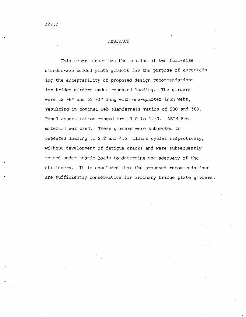
This report describes the testing of two full-size
slender-web welded plate girders for the purpose of ascertain
ing the acceptability of proposed design recommendations
for bridge girders under repeated loading. The girders
were 32'-6" and 35'-3" long with one-quarter inch webs,
resulting in nominal web slenderness ratios of 200 and 380.
Panel aspect ratios ranged from 1.0 to 1.50. ASTM A36
material was used. These girders were subjected to
repeated loading to 2.2 and 4~5 ~illion cycles respectively,
without development of fatigue cracks and were subsequently
tested under static loads to determine the adequacy of the
stiffeners. It is concluded that the proposed recommendations
are sufficiently conservative for ordinary bridge plate girders.

327.7
1.1 Background
1. INTRODUCTION
-2
The present effort is part of a continuing study of
the behavior of slender-web welded plate girders. Many contri
butions have been made in this field, both in Europe and in this
country, with studies having been in progress at Lehigh Univer-
sity since 1957.
For many years the attainment of the critical buckling
stress in the web was considered to be the limit of structural
usefulness for girders. As evidenced by many of the nearly three
hundred entries in an early literature survey,(l) work progressed
toward a high degree of development in the predicting of this
critical stress.
The linear buckling theory having been finally demon-
strated to give an overly conservative estimate of the static
strength of slender-web plate girders, (1,2,3,4) design practice
moved forward early in this decade to take advantage of inherent
post-buckling strength.(5)
A question arose at this point as to whether or not
these advances in the knowledge of girder behavior could be ap
plied in the case of repeated loading, that is, for bridge
girders.(6) To answer this question and to study the behavior of
slender girders under repeated loading, especially the effect of
327.7 -3
out-of-plane web deflections, a testing program was begun at Lehigh
University in 1960. Fatigue tests of nine large-size welded plate
girders were carried out under loading conditions of bending, shear,
and combined bending and shear.(7) From the results of these and
other tests, (8,9) plate bending stresses due to repeated lateral
web deflections were concluded to be a primary cause of fatigue
cracks along web boundaries.(lO) In addition, a method was de-
veloped for estimating these stresses from measured web deflections.
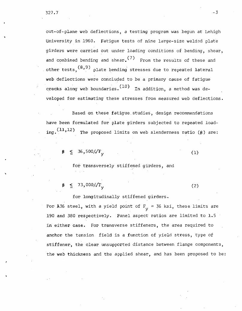
Based on these fatigue studies, design recommendations
have been formulated for plate girders subjected to repeated load
ing.(11,12) The proposed limits on web slenderness ratio (~) are:
~ < 36,500//F (1)Y
fo1;' transversely stiffened girders, and..
f) < 73,000//F (2)Y
for longitudinally stiffened girders.
For A36 steel, with a yield point of F = 36 ksi, these limits arey
190 and 380 respectively. Panel aspect ratios are limited to 1.5
in either case. For transverse stiffeners, the area required to
anchor the tension field is a function of yield stress, type of
stiffener, the clear unsupported distance between flange components,
the web thickness and the applied shear, and has been proposed to be:
..
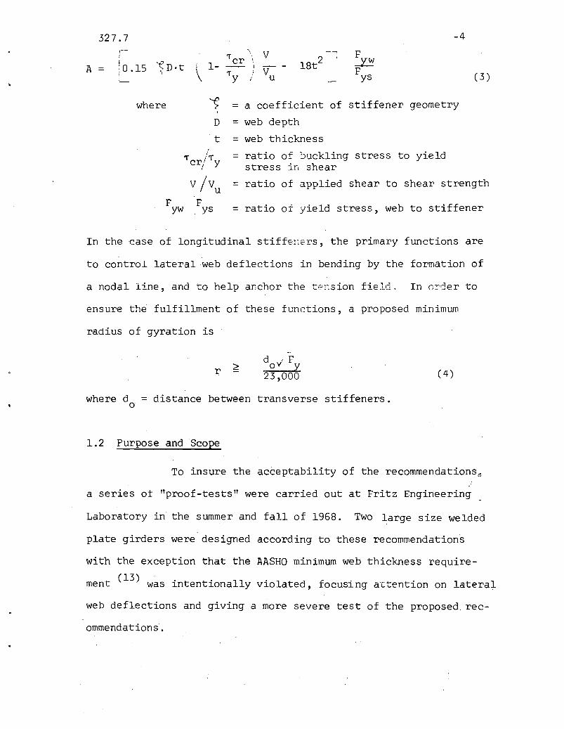
327.7 -4,- '\ V Fi 'fcr 18t2
,I '(D·t
\ ..1.Y:!A :0.15 i 1- -- I V -= F" \ 'fy (3)/ u ys
where ~ = a coefficient of stiffener geometry\
D = web depth
t = web thickness! = ratio of buckling stress to yieldTcr/'fy stress in shear
V/Vu = ratio of applied shear to shear strength
F F ratio of yield stress, web to stiffeneryw ys =
In the case of longitudinal stiff'2I~e:cs, the primary functions are
to control lateral web deflections in bending by the formation of
a nodal line, and to help anchor the tension field. In o~der to
ensure the fulfillment of these functions, a proposed minimum
radius of gyration is
r
•..
d . FOV Y
23,000 (4 )
where d = distance between transverse stiffeners.o
1.2 Purpose and Scope
To insure the acceptability of the recommendations~
a series ot Ilproof-testsll were carried out at Fritz Engineering
with the exception that the AASHO minimum web thickness require-
(13) '. . 11' fment was lntentlona y vlolated, ocusing a'ctention on lateral
web deflections and giving a more severe test of the proposed rec-
ommendations.

327.7 -5
Two parameters that were of particular interest in this
investigation are the web slenderness ratio 8, and the panel as-
pect ratio ~. In particular, what kind of performance under
repeated loading could be expected from girder web panels with
a and 8 at the allowable upper limits? These tests were run
not only in fatigue, but were also carried out statically to de
termine the ultimate load of the individual panels.
Another item of interest was the size and arrangement of
the stiffeners, borh longitudinal and transverse. To be studied
were the adequacy of one-sided stiffeners and the behavior of
stiffener intersections having the longitudinal stiffener
connected to or cut short from the transverse ones. Most of the
stiffeners were instrumented to provide an indication of
the stress development in the stiffeners and the distribution of
st:resses when an adjacent panel was loaded to its maximum capacity.
A further objective was the collection of additional
web deflection data for the computation 6f web boundary stresses,
so that an S-N curve could be established more precisely. It was
anticipated that tests performed on these girders would provide
some information for the modification, if necessary, of the pro
posed design recommendations. In this report are presented the
essential data of the proof-testing and the discussion of the
results. A more complete discussion of the behavior of slender~
web girders in general may be found in Ref. 7 and 10, the latter
deals specifically with the development of the method for com
puting plate bending stresses from web deflections.

327.7 -G
Whereas the proposed design recommendations set limits
on the various parameters in terms of the yield point F , they
two girders tested in this investigation were of A36 material.
The validity of the limits for high strength material could be
derived from results of earlier static tests(14,15) and through
comparison of fatigue properties of materials. This will be
discussed later in the report.
327.7
2. THE TEST GIRDERS AND SET-UP
-7
2.1 Design Criteria and Description of Specimens
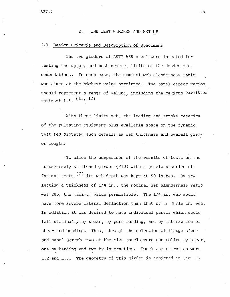
The two girders of ASTM A36 steel were intented for
testing the upper, and most severe, limits of the design rec-
ommendations. In each case, the nominal web slenderness ratio
was aimed at the highest value permitted. The panel aspect ratios
should represent a range of values, including the maximum per~itted
t . f 1 5 ( 11 , 12 )ra lO -0 .•
With these limits set, the loading and stroke capacity
of the pulsating equipment plus available space on the dynamic
test bed dictated such details as web thickness and overall gird-
er length.
To allow the comparison of the results of tests on the
transversely stiffened girder (FlO) with a previous series of
fatigue tests, (7) its web depth was kept at 50 inches. By se-
lecting a thickness of 1/4 in., the nominal web slenderness ratio
was 200, the maximum value permissible. The 1/4 in. web would
have more severe lateral deflection than that· of a 5/16 in. web.
In addition it was desired to have individual panels which would
fail statically by shear, by pure bending, and by interaction of
shear and bending. Thus, through the selection of flange size'
and panel length -two of the five panels were controlled by shear,
one by bending and two by interactiono Panel aspect ratios were
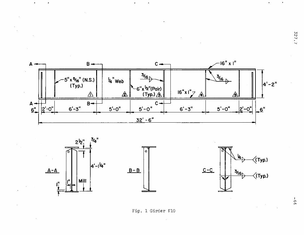
1.2 and 1.5. The geometry of this girder is depicted in Fig. 1.
327.7 -8
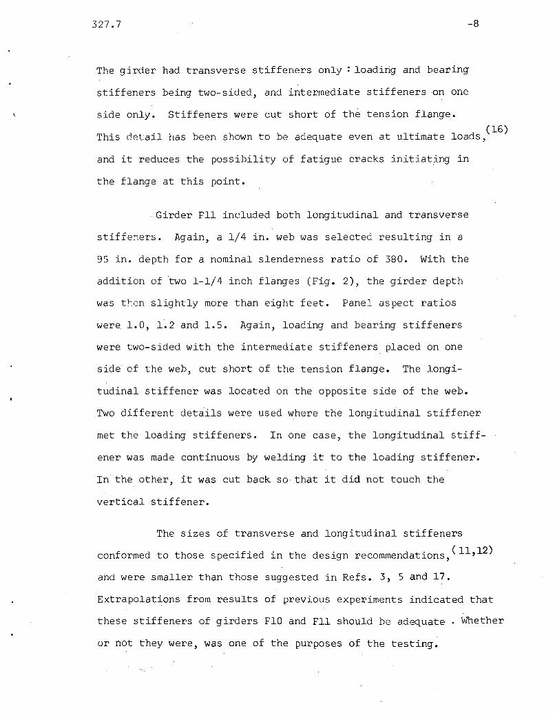
The gi.rder had transverse stiffeners only: loading and bearing
stiffeners being two-sided, and intermediate stiffeners on one
side only. Stiffeners were cut short of the tension flange.
This detail has been shown to be adequate even at ultimate 10ads,(16)
and it reduces the possibility of fatigue cracks initiating in
the flange at this point.
Girder Fll included both longitudinal and transverse
stiffeners. Again, a 1/4 in. web was selected resulting in a
95 in. depth for a nominal slenderness ratio of 380. With the
addition of two 1-1/4 inch flanges (Fig. 2), the girder depth
was t~en slightly more than eight feet. Panel aspect ratios
were 1.0, 1.2 and 1.5. Again, loading and bearing stiffeners
were two-sided with the intermediate stiffeners placed on one
side of the web, cut short of the tension flange. The longi-
tudinal stiffener was located on the opposite side of the web.
Two different details were used where the longitudinal stiffener
met the loading stiffeners. In one case, the longitudinal stiff-
ener was made continuous by welding it to the loading stiffener.
In the other, it was cut back so that it did not touch the
vertical stiffener.
The sizes of transverse and longitudinal stiffeners
conformed to those specified in the design recommendations,(11,12)
arid were smaller than those suggested in Refs. 3, 5 and 17.
Extrapolations from results of previous experiments indicated that
these stiffeners of girders FlO and Fll should be adequate . Whether
or not they were, was one of the purposes of the testing.

327.7
Fabrication techniques were not specified except that
-9
the girders should be assembled according to common practice and
be welded in accordance with the American Welding Society Spec-
'f' t' (18)l lca lons. The sizes of the fillet welds were allowed in
some instances to be smaller than that permitted by AWS. Nominal
weld sizes used are indicated in Figs. 1 and 2.
2.2 Properties and Test Loads of Specimens
Up to this point, any discussion of dimensions of the
girders and yield stress levels has been in terms of nominal de-
sign values. Upon delivery of the girders, average width and
thickness were obtained for the webs and flanges by direct mea-
surement at a number of locations, and the values shown in Table
1. Tensile specimens, some oriented parallel to and some perpen-
dicular to the direction of rolling, were cut from extra lengths
of flange and web components, and tested by the investigators to
determine the static yield stress level and the tensile strength
of the material. These values are presented in Table 2.
With the measured dimensions and material properties
known, analyses were made for each panel to predict its static
ultimate strength and mode of failure. These analyses were
carried out according to recommended procedures which are out-
lined'in Refs. 11 and 12. The ultimate strength as well as the
web buckling loads, for comparison, are listed in Table 3 for all
327.7 -10
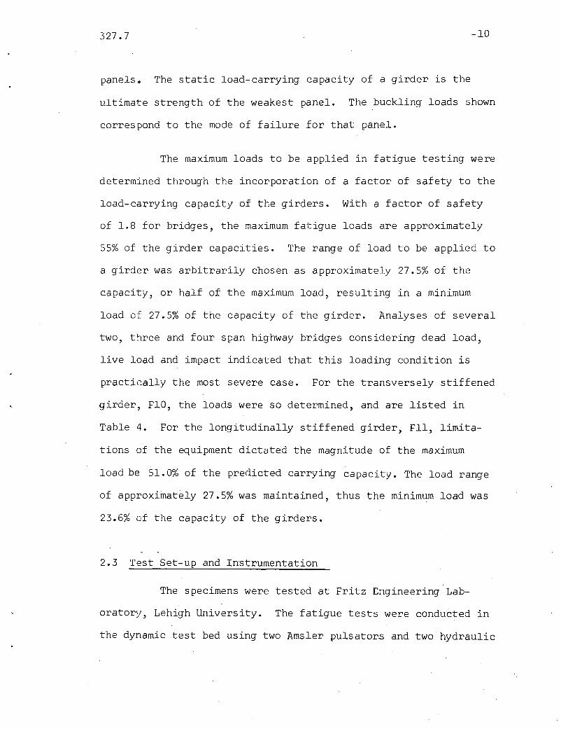
panels 0 The static load-carrying capacity of a girder is the
ultimate strength of the weakest panel. The buckling loads shown
correspond to the mode of failure for that panel.
The maximum loads to be applied in fatigue testing were
determined through the incorporation of a factor of safety to the
load-carrying capacity of the girders. With a factor of safety
of 1.8 for bridges, the maximum fatigue loads are approximately
55% of the girder capacities. The range of load to be applied to
a girder was arbitrarily chosen as approximately 27.5% of the
capacity, or half of the maximum load, resulting in a minimum
load of 27.5% of the capacity of the girder. Analyses of several
two, t~ree and four span highway bridges considering dead load,
live load and impact indicated that this loading condition is
practically the most severe case. For the transversely stiffened
girder, FlO, the loads were so determined, and are listed in
Table 4. For the longitudinally stiffened girder, Fll, limita
tions of the equipment dictated the magnitude of the maximum
load be 51.0% of the predicted carrying capacity. The load range
of approximately 27.5% was maintained, thus the minimum load was
23.6% of the capacity of the girders.
2.3 Test Set-up and Instrumentation
The specimens were tested at Fritz Engineering Lab
oratory, Lehigh University. The fatigue tests were conducted in
the dynamic test bed using two Amsler pulsators and two hydraulic

327.7 -11
jacks to furnish the loads at about 250 cycles per minute. The
static tests were carried out in a Baldwin hydraulic universal
testing machine with a capacity of 5,000,000 pounds.
In each case, the girder was simply supported, and was
braced laterally by means of 2-1/2 inch diameter pipes attached
to the vertical stiffeners at one end and to a special supporting
beam at the other. Figures 3 and 4 show FlO in the fatigue set-up
and Fll in the static set-up, respectively.
In addition to the girders' ability to survive a speci-
fied lifetime of repeated loading, information was sought on four
distinct aspects of girder behavior: (1) load versus vertical
deflection of girder such as those shown in Figs. 5 and 6; (2) out-
of-plane web deflection; (3) stresses on surfaces of the web ad-
jacent to stiffeners and (4) stiffener stress distribution. The
instrumentation by means of which this information was obtained
" "I h t d· " "d t (7)was Slml ar to t a use ln prevlous glr er ests.
Load-deflection behavior was monitored by the use of
Ames one-thousandths inch dial gages located at mid-span and at
both ends of each girder. Support deflections were in this way
excluded from the girder deflection.
Electrical resistance strain gages were used to measure
web and stiffener strains during the static tests before and after
the fatigue loading, as well as to monitor web strains when fatigue

327.7 -12
testing was in progress. Since cracks might occur at panel bound-
aries when the web plate has relatively large lateral deflec
tions,~O) strain gages were placed on the web as close to the
flanges and stiffeners as possible. Linear and rosette gages
(SR-4 Al and AR1) were employed according to the gage location
shown in Fig. 7. All gages, both on web and on stiffener, were
placed back-to-back so that the surface stress, average stress
and secondary bending stress could be differentiated. The
majority of strain gage outputs were recorded by means of a
B & F Strain Recorder with an IBM Keypunch attached; the re-
mainder were handled with self and manual-balancing strain in-
dicators.
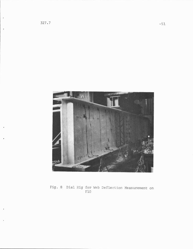
Out-of-plane web deflections were measured extensively
by means of Ames dial gages mounted on a rigid framework (Fig. 8).
For girder FlO, with the origin for cartesian co-ordinates being
defined at girder mid-height, deflection readings were taken at
+ + + + +.y = 0, -5, -9, -15, -18 and -21 lnches. These readings were
taken at some fifty-five locations along the girder length. In
the case of girder Fll, for a better detection of the influence
on the web behavior of the longitudinal stiffener, deflection
readings were taken at more locations: y = +6.5, +16.5, +21.5,
+25.5, +28.5, +31.5, +40.5 and +44.5 above the horizontal center-
line, and at y = -3.5, -15.5, -25.5, -35.5, -40.5 and -44.5
below. Again readings were taken at nearly fifty positions along
the length of the girder. These web deflections serve the dual

327.7
purposes of affording qualitative insight into the web behavior
-13
under load, especially above the buckling load, and of providing
a means of computing the plate bending stresses in the web.
2.4 Expected Fatigue Results and Static Failure Modes
Preliminary stress analyses and the S-N curve of pre
vious fatigue tests~O) afforded an indication as to whether or
not fatigue cracks of the web be expected to form.
The plate bending stresses along web boundaries of
girder FlO were sufficiently low so that'this girder was not
expected to have any fatigue cracks before the attainment of
two million cycles. In fact, cracks were not anticipated even
at ten million cycles. In the case of Fll, with a much higher
web slenderness ratio and relatively large web deflections,
stresses at some locations were comparable to those which caused
fatigue cracks-at around two million cycles in previous girders.
It was felt before the test that cracking might be observed.
Specifically, the area adjacent to the intermediate stiffener
and above the mid-depth of the girder was regarded as the most
likely place to develop a crack.
The static failure modes for girders under various
loading conditions have been treated in detail in the litera
ture~(1,14,15,17)The emphasis in the present tests was to inves
tigate stiffener behavior and to collect additional web deflection
327.7 -14
data. As much as possible, panels adjacent to transverse stiff- .
eners were loaded to failure in shear or combined shear and
bending so as to develop tension-field action in the panel and
compression in the stiffener. The failure mode of every panel
was expected to confirm the prediction shown in Table 3.

327.7
3.
3.1 General Procedure
TESTING OF SPECIMENS
-15
The testing of each girder was carried out in three
phases: initial static loading, fatigue testing, and static
tests to failure. The first two took place in the dynamic test
bed with loads applied by Amsler hydraulic jacks. The static
tests to failure were conducted in the Baldwin five-million
pound universal testing machine. The procedure followed was
the same for both girders.
The initial static loading phase consisted of a preload
to P for alignment, for minimizing the effects of residualmax
stresses, and for settling the test set-up; then another loading
to P for strain gage and web deflection readings. Themax
quantitative determination of girder web deflections at P andmax
P. provided data for the prediction of plate bending stress,mln
and hence the possibility of fatigue cracks, if any.(lO)
3.2 Fatigue Tests
After the measurement of deflections and strains, the
fatigue testing could begin with two million cycles as a minimum
goal. At the rate of 250 cycles per minutes, that took about
130 hours, or more than five days of continuous cycling.

327.7 -16
While under fatigue loading, the girders were closely
examined at frequent intervals (initially two, later three or
four hours, day and night) with floodlight and magnifying glass
in an effort to detect macroscopic fatigue cracks. Monitoring
of dynamic strains ·on the web of F 11 was performed occasionally.
When the tests had run to two million cycles without
any cracks having been observed, loading was allowed to con-
tinue for a period of time dependent on the expected behavior
of the girder and on the scheduling demand for the testing
facilities. The test of girder FlO was terminated after 2.2
million cycles, whereas Fll was allowed to run to 4.5 million
cycles, (slightly more than twelve days, continuously). After
termination of the fatigue test, each girder was inspected at
P • Neither showed any evidence of fatigue cracks.max
3.3 Static Tests
With fatigue tests successfully completed, the two
girders could be loaded statically to failure for the exam-
ination of stiffener behavior. Also observed were the web
deflections beyond thos·eat the maximum loads of the fatigue
testing.
Since the function of transverse stiffeners to be
examined was their ability to carry tension-field-induced com-
pression, shear failure of girder panels was intended. Panels

327.7 -17
that would have incurred bending failure (Table 3) were rein
forced with a cover plate so as to allow testing of the panels
in shear. The reinforcement of girder panels is shown in Figs.
9 and 10 where the failure modes of each test are also sketched.
Girder FlO
The complete testing history of this girder is depicted
by Figs. 5 and 9. The first test (Tl) resulted in failure of
panel 4 at a load magnitude of 170 kips. At 130 kips yield lines
commenced in the top flange over panels 2, 3, and 4 as well as
in the web of panel 4. By the time 165 kips were applied, prac
tically the entire tension diagonal of panel 4 had yielded.
Loading was stopped at 170 kips when the web deflection was judged
excessive, and flange yielding was becoming pronounced. The
girder was reinforced by welding a cover plate over panels 2, 3,
and 4 and adding a transverse stiffener in panel 4.
The cover plate and the additional stiffener increased
the bending strengths of panels 2 and 3 and the static strength
of panel 4, so that the failure for the second test (T2) would
be confined to panel 1 alone. Indication of tension field by
yielding was quite pronounced at 180 kips. At 184.5 kips fail
ure occurred when girder deflection increased without further
increase in load. A photograph of the panel after failure is in
cluded as Fig. 11. The girder was reinforced by welding a trans
verse stiffener in panel 1 (Fig. 9).

327.7 -18
At the last load of test T2 ,yielding was seen to ini
tiate in panel 5. After the reinforcing of panel 1 and resumption
of loading, panel 5 continued to take load in test T3. At 190
kips the small panel beyond panel 5 yielded and the web beyond the
bearing stiffener deformed. Panel 5 lost proper anchorage for its
tension field and the load fell off. Figure 12 is a photograph of
panel 5 after the test. No failure of any stiffener was observed
in girder FlO.
Girder Fll
All three panels of this girder were taken to ultimate
load. The load-deflection curve, Fig. 6, and the sketches of fail
ure modes in Fig. 10 may be used to trace the testing history.
At about twice the maximum fatigue loads, yielding
initiated at the bearing stiffeners. Since these and the loading
stiffeners had been inadvertently underdesigned for static test
ing, doubler plates were attached by clamping and then welding in
place at various stages of testing.
In test Tl, the yielding pattern indicating a tension
field was beginning to form in panel 1 at 200 kips. Yielding
had also started in the upper flange near the loading points and
in the loading stiffeners. At 215 kips, the longitudinal stiff
ener was noticably d€flected out-of-plane in panel 1 at a place
where the stiffener was not straight before loading. Doubler
plates were clamped to this stiffener at 220 kips but in vain.

327.7
It failed at 230 kips by deflecting with the web and out-
-19
of-plane as tension field deflections increased. The test was
stopped at this point. A vertical stiffener was fitted to the
contour of the web and welded in place.
Test T2 was to bring panel 2 to failure for observing
and monitoring the behavior of stiffeners. As loads increased,
it gradually became clear that the deformation of panel 1 in test
Tl had been too excessive and that the reinforcements were not
sufficiently strong to curtail the additional web deflection.
Also, the general area below the loading points incurred ex
tensive yielding with lateral deflection of the web between the
loading stiffeners. The test was interrupted after 275 kips for
further reinforcement by adding stiffeners and a cover plate as
shown in Fig. 10.
Panel 2 failed in interaction of high shear and bending
moment in test T3 at 294 kips. Before that, and after the ini
tiation of yielding along the tension diagonal of the panel, yield
lines also developed along the tension diagonal of panel 3 and
beyond the support. The failure of T3, however, was in panel 2
and is typical of panels under the same loading condition. (1)
The girder was once more reinforced with cover plate
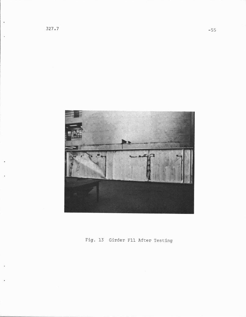
and stiffeners (Fig. 10), and then subjected to loads. At 330 kips,
excessive deformation and yielding beyond the support near panel 3

327.7 -20
were evident. This area failed as an attempt was made to
increase the load further. An overall photograph of the girder
after completion of the static tests is included as Fig. 13.
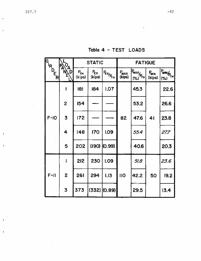
The experimental strength of each test panel is listed
in Table 4, together with the predicted values.

327.7
4. ~EHAVIOR AND STRESS OF WEB AND STIFFENERS
-21
Initial deflections of web, or out-
4.1 Lateral Deflection and Stresses in Web
Qualitatively the web deflections of girder FlO and
Fll were the same as those obtained from other test girders
(1, 7, 8, 14, 15, 17 )
. of-flatness, existed before any application of loads. As loads
were applied to the girders, lateral deflections increased
gradually corresponding to the loads. The cross-sectional
. shapes at several transverse sections of the girders are shown
as examples in Fig. 14, with exaggerated scales. The deflection
pattern of a web panel depended on the loading condition. The
def~ected cross-sectional shapes in Fig. 14 depict a diagonal
pattern in many panels which is the result of tension field
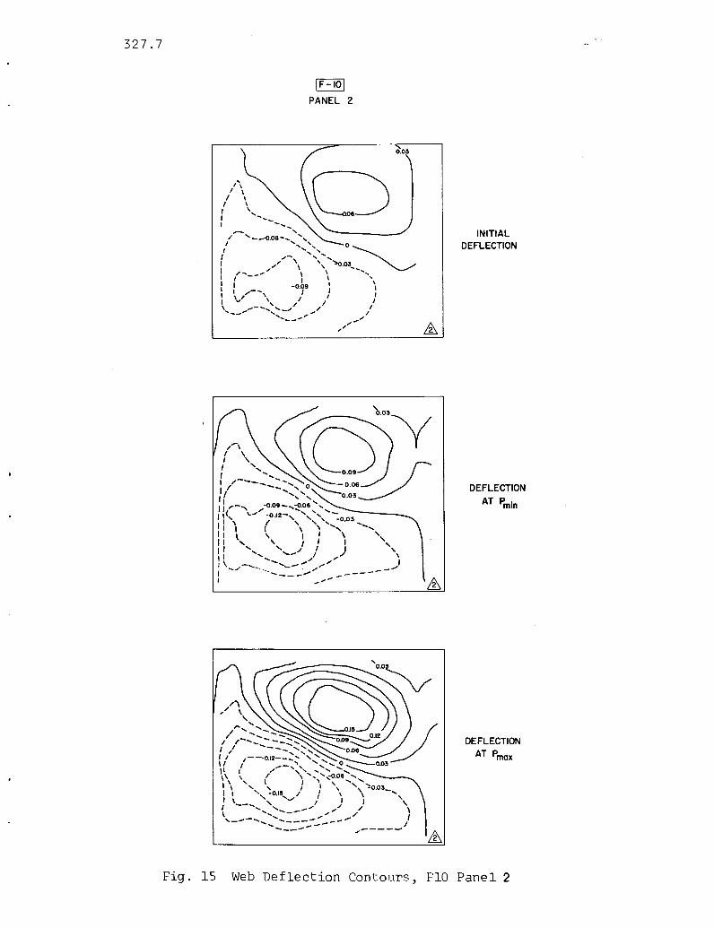
action (3). This pattern is clearly seen in Figs. 15 and 16,
contour plots of the lateral deflections of two web panels.
In Fig. 15, the gradual change of contour lines from one load to
the other indicates the gradual change of web deflection and the
forming of the tension field along a diagonal. The contour lines
of Fig. 16 show the effect of the longitudinal stiffener on the
deflection pattern of the web panel. Obviously this longitudinal
stiffener prevented the upper part of the web from developing
large lateral deflections such as those recorded in the lower portion
of the web which were quite high at a load of about 65% of static
strength.

327.7 -22
It is the magnitude of the web deflections which were
of interest in the testing; for the measured magnitudes could be
used in an analysis to predict the web boundary stresses. Some
measured data are shown in Table 5. The maximum initial de-
flections were 0.16 in. and 0.66 in. or 0.63 and 2.52 times the
web thickness for FlO andFll respectively. Both were within
the AWS limit of permissible out-of-flatness.(18) The maximum
out-of~plane deflections at approximately 55% of the panel
strength were 1.67 and 4.30 times the web thickness for FlO and
Fll. It is important to note that the maximum fatigue loads
were decided according to the panel strength which in turn
depends on the web thickness.
By using measured deflectlons, out-of-plane bending
stresses of the web plate were predicted and the magnitudes at
some points are shown at their approximate locations in Fig. 17.
These were ranges of fatigue stresses in the web at its junction
with the stiffener or flange, and were found to be responsible for
any previous fatigue cracks at these junctions. (lO)The accuracy of these
predictions were checked against stresses from strain gages
(Fig. 18) and were considered acceptable.
The highest predicted range of plate bending stress
for girder FlO was about 16 ks i and that for girder Fll I,vas
approximately 23 ksi. In comparison with results froIT, p2evious

327.7
fatigue tes~i, Fig. 19, it is obvious that the possibility ot
incurring cracks was no~ high tor girder FlO at three or four
million cycles, whereas Fll might develop cracks at around two
million cycles. The fatigue testing of FlO was, therefore,
terminated shortly after two million cycles; and girder Fll
-23
carried to 4,500,000 cycles when equipment availability dictated
stopping.
After fatigue tes~ing, ~he behavior of the webs and
the eventual failure of the panels under static load, as de-
scribed in Section 3.3, showed no extraordinary phenomena. The
failure modes were generally as predicted, conforming to those
d . . . (1, 17) F b h . dreporte ln prevlous statlc tests. or ot glr ers,
yielding at the general area of anchorage for tension field in
the last test panel caused failure of the panel to occur below
the predicted loads. This, too, agreed well with results of pre-
vious tests.
4.2 Stiffener Behavior and Stresses
There was no yielding or buckling of intermediate
transverse stiffeners even when an adjacent panel failed in
tension field action. (Only a contour-fitting reinforcement
stiffener, used for repair, bent ou~ ot plane due to excessive
web deflection ·of girder Fll; test T2, Flg. 10). The loading and
bearing stiffeners of this girder yielded near their contact zones
because of insufficient size; however the yielded ar€as were not
anchoring a tension field and reinforcements corrected the under-

327.7 -24
design (Sec. 3.3). The longitudinal stiffener of girder Fll, on the
other hand, deformed out of its plane for a short length near
(x = - 122) where initial out of straightness of about 1/4 in.
had been observed.
In addition, the intermediate transverse stiffeners and the
longitudinal stiffener twisted slightly when adjacent web plates
deflected laterally. The amount of twi~ting differed along the
length of a stiffener as well as from orle stiffener to another.
Since it is the relative rotation betwe~n the web and the stiffener
that is significant for web plate bending stresses, the absolute
rotation of the stiffeners were not recorded. Past attempts to
measure relative rotation had not been sufficiently accurate,
therefore measurements were not made in these tests. During
repeated loading, the longitudinal stiffener in panel 1 of girder
Fll appeared to twist relatively more than other stiffener. Being
the longest of all stiffeners, and in a panel of highest slenderness
and aspect ratio and highest lateral deflection, a relatively
higher twisting was expected.
Both the transverse and the longitudinal stiffeners deflected
perpendicular to the plane of the web. Measurements indicated
that maximum deflections of the transverse stiffeners at P weremax
less than 1/10 of the web thickness. Such a magnitude was considered
small enough to be ignored in the prediction of web plate bending
stresses.(lO) At the maximum fatigue load, the maximum deflection
of the longitudinal stiffener was approximately 1/2 of the web
thickness. This deflection with the web, together with the twistinr

327.7 -25
significantly reduced the plate bending stresses of the web at the
stiffener and thus reduced the possibility of early fatigue cracks
along this longitudinal stiffener.
The directions of deflections of one-sided stiffeners
generally followed the deflection patterns of the web plates. Con
sequently, the directions·of the deflections differed from panel
to panel and could be toward or away from the stiffener, as can be
detected from Fig. 14. This phenomenon strongly influenced the
stresses in the stiffener plates, and is discussed below.
Stresses in the transverse intermediate stiffeners were
computed from measured strains. The average uni-axial stresses
calculated from measurements of back-to-back strain gages are shown
in Fig. 20 for a stiffener (x = - 165) of girder FlO when the
neighboring panel failed in shear. Tension field action of the
panel demanded anchorage at the upper part of the stiffener, reSUlting
in high compressive stress in that region. (At the corner of the
stiffener-web-flange junction, the vertical compressive strain
in the web indicated that yielding had occurred.) At a point in
the stiffener six inches below the flange, the compressive stress
was about 13 ksi, much less than the yield point of the material.
Further down along the stiffener-to-web junction, the stress mag
nitude decreased linearly to zero at the bottom, where no tension
field anchorage took place. By comparison, the stresses at the
free edge of the stiffener changed from tension in the upper
portion to compression below. This was the obvious result of the
edge loading applied to the one-sided stiffener, with deflection of
the stiffener plate concave along the loading edge.

327.7 -26
When a longitudinal stiffener was present, tension field
action took place in the sub-panels and the stress distribution
in a transverse stiffener adjacent to this panel reflected this
subdivision. For the stiffener at x = - 154 at the ultimate load
of panel 1, the axial stresses are shown in Fig. 21 with straight
lines connecting data points. Below the longitudinal stiffener,
where a tension field was prominent, the decreasing of compressive
stress towards the bottom was evident along the stiffener-to-web
junction, just as in the case described in the last paragraphs.
Above the longitudinal stiffener, lower stresses were recorded,
particularly at the location opposite the longitudinal stiffener.
It is regrettable that there existed no strain gages just below
the horizontal stiffener for a better picture of stress distri
bution in that vicinity. Nevertheless, the highest recorded
axial stress of about 19 ksi was far below the yield point of
the material. Stresses in the web along the transverse stiffener
confirmed these magnitudes, as are indicated for two points in Fig.
21.
It is interesting to compare the stress distribution of
the stiffeners of Figs. 20 and 21. Both were at the end of a girder
next to a failed panel and a small end panel (Figs. 9 and 10).
For the case without a longitudinal stiffener, the small end panel
yielded and the tension field anchorage was primarily by the flange
of the girder. The stresses in the stiffener were relatively low.
Where the longitudinal stiffener existed, the small end panel also
yielded, as well as the upper sub-panel. The longitudinal stiffener
327.7 -27
deformed, thus the transverse stiffener had to take higher stresses.
Had the longitudinal stiffener been straight it would certainly
have shared the duty of anchoring and would have reduced the
stresses in the transverse stiffener.
For the longitudinal stiffener in panel 1 of girder Fll,
the magnitude of stresses at several points along its length
are shown in Fig. 22. Near the transverse stiffener at x = - 154,
the stresses were compressive because of tension field anchorage.
At the other end where the stiffener was not continuous and there
was no tension field in the next panel, the stresses were practically
zero. In between, where local deformation of the stiffener plate
occurred (around x = - 122), it was not capable of sustaining
axial compression, thus resulting in negligible stiffener stresses
in the vicinity. At mid-panel, the deflection of the stiffener
towards its free edge caused in-plane bending of the stiffener
plate and hence tension stresses along the free edge.
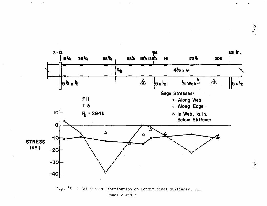
In panels 2 and 3 where the longitudinal stiffener was
continuous, the stress magnitudes were uniformly low along the web
(Fig. 23) even at the failure of panel 2 by combined shearing and
bending of the girder. Again, as in panel 1 stresses at web points
just below the stiffener agreed well with these magnitudes. What
differed from panel 1 was that the web and stiffener deflections
under load were towards the web; the free edge of the stiffener
plate thus was under high bending stresses at the middle of each
panel.

327.7 -28
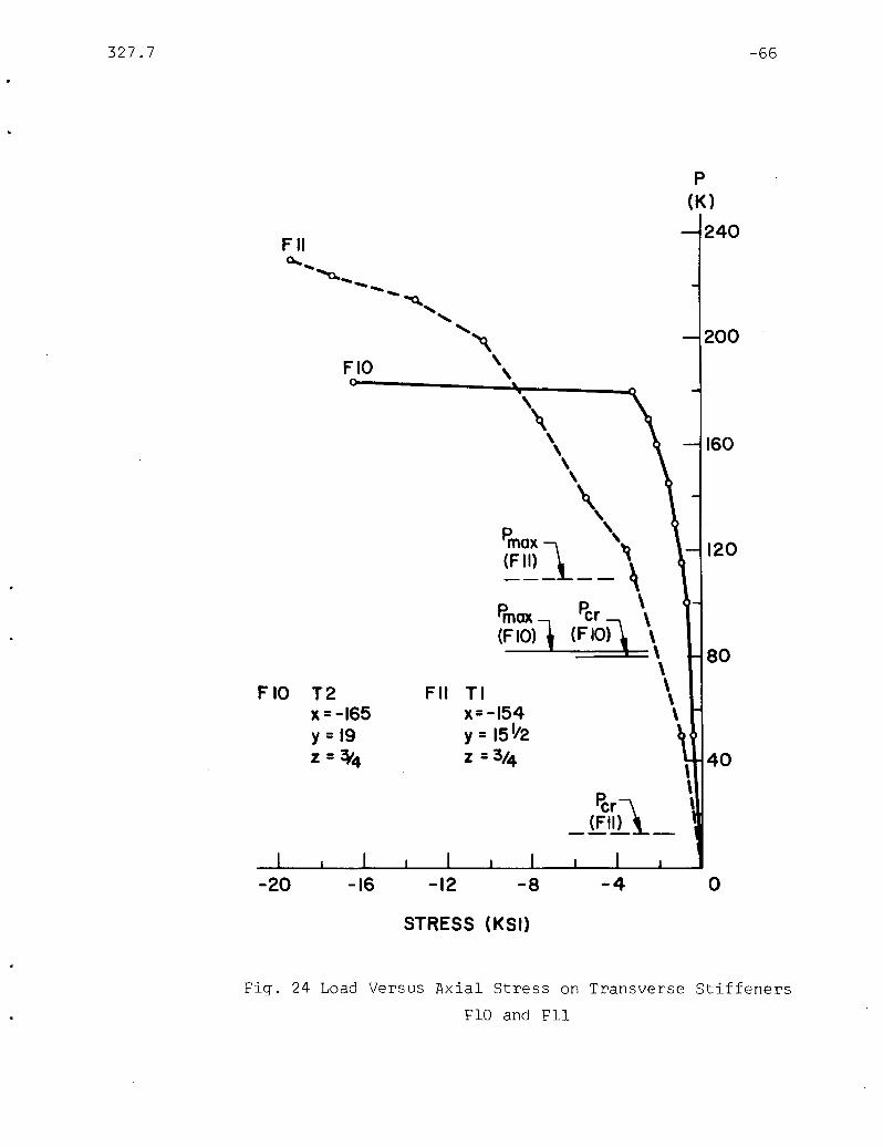
It is also of interest to know that stresses in stiffeners
developed only at high loads near the static strength of the web
panels (Figs. 24 and 25). For both transverse and longitudinal
stiffeners, the web buckling load bore no significance in the
development of stresses. At the maximum fatigue loadS stiffener
stresses were practically negligible. Even the surface stresses
of the longitudinal stiffener, reflecting out-of-plane bending, could
be considered insignificant at the maximum fatigue load.

327.7
5. DISCUSSION
5.1 Slenderness and Aspect Ratios for Webs
The results of the proof-testing demonstrated that no
fatigue cracks occurred in the two welded plate girders of A36.
steel with maximum recommended web slenderness and panel aspect
ratios under the most severe loading conditions. It is the intent
here to discuss the factors governing fatigue cracks of the web
and to judge the adequacy of the recommended limits for girder
webs.
As has been discussed earlier, webs of girder panels
are not initially flat and deflect further under load. Plate-
bending stresses are thus produced which are the primary cause of
web cracks in repeated loading. Therefore, the factors influencing
the formation of cracks are: 1) the initial deflection of web,
2) the increase of web deflection under load, 3) the magnitude
and range of loading, 4) corresponding plate bending stresses,
and 5) the properties of the web material in terms of a stress-
fatigue life relationship.
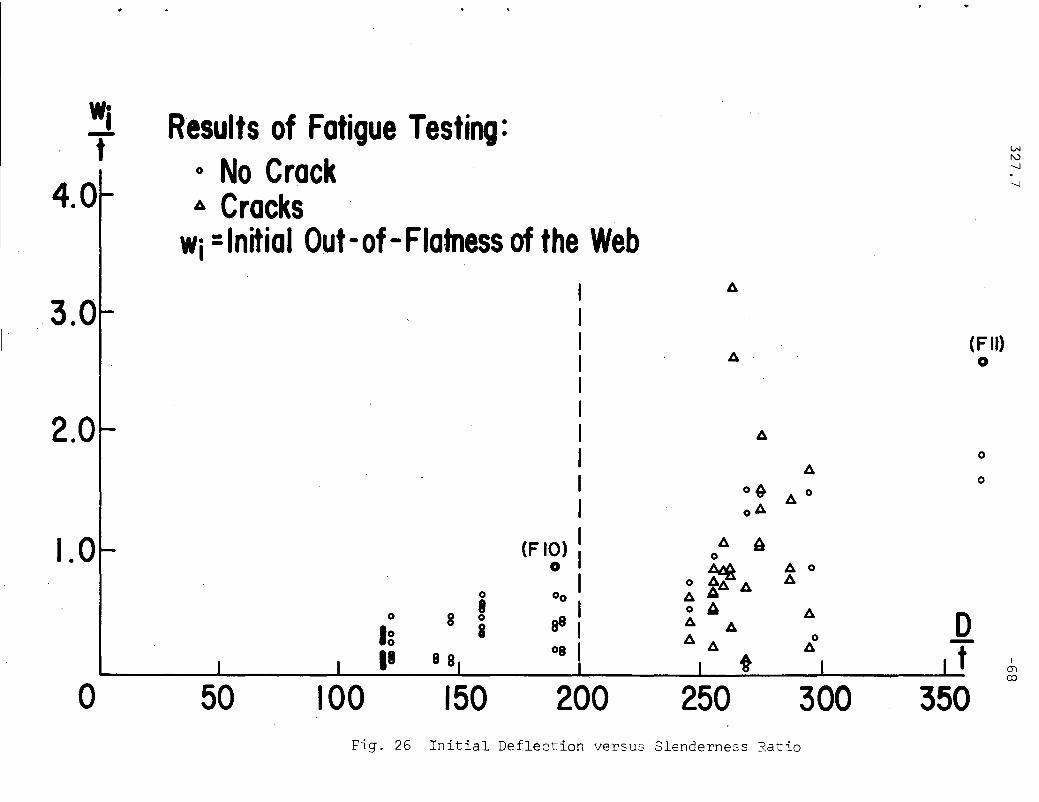
The magnitude of initial deflection (w.) or out-of-flatness,1
depends on the thickness of the web (t), its slenderness ratio
(~), the panel aspect ratio Cal, as well as the flatness of the
web plate before fabrication and the technique of fabrication.
For any girder, this magnitude of initial deflection can not be
controlled by the designer.

327.7
Measurements on test girders have furnished a diagram relating
-30
w./t and ~ for girder panels with web thicknesses of 3/16 to 3/81
in. and aspect ratios of 0.8 to 1.5 (Fig. 25). From this diagram.
it may be stated that for a given web thickness, the magnitude
of initial deflection increases with the web depth. Also from
Table 5, it can be said that a given value of S, the amount of
initial out-of-flatness is larger for longer panels. It follows
that, generally, for a given set of a and S values, the initial
deflection is inversely proportional to the web thickness. Because
the two proof-test girders were built of 1/4 in. plates, their
initial web deflections were consequently higher than would have
been recorded for 5/16 in. or thicker webs. In fact, the magni-
tude of the initial web deflection of the test panels of girders
FlO and Fll were the highest recorded for their respective slender-
ness ratios (Fig. 25).
The increase of lateral deflections under load is a function
of the load magnitude, the panel geometry, the web boundary con-
ditions, and the magnitude of the initial out-of-flatness. Efforts
have been made to predict these deflections but only a very limited
number of very simple cases were examined.(19) While studies
are being carried out for more general conditions of panel geometry
and web boundary conditions, experimental results indicate that
the increase of web deflections in practical load range is generally
proportional to the magnitude of the initial web deflections.
(See, for example, Table 5 in this re port and Fig. 93 0 f Ref. 8).
It follows from this and the statement of the last paragraph that,
for a given value of S, thinner webs deflect more than thicker

327.7 -31
webs, and the webs of girders FlO and Fll deflected more than those
of girders with 5/16 in. webs when subjected to load.
As pointed out earlier (Sec. 2.2), the load magnitude
and the load ranges applied to the test girders were the most
severe condition anticipated for.bridge girders. Consequently
the web deflection conditions of the girders FlO and Fll represented
cases much more severe than commonly encountered. What remains
to be found is the relationship between thse web deflections and
the plate bending stresses at the web boundaries, and to compare
them with the fatigue properties of the material.
The web plate bending stresses can be estimated by using
the method of Ref. 10. For ordinary web boundary conditions, the
relationship appears to be linear between the range of stresses
and the range of web deflections (corresponding to the range of
applied loads),Fig. 26. Higher lateral deflections create
higher plate bending stresses. Higher initial deflection thus
cause higher plate bending stresses; and girders FlO and Fll
should have relatively much higher stresses than would be expected
of thicker web plates.
The highest web boundary plate-bending stresses were only
about 16 ksi and 23 ksi for girders FlO and Fll, respectively.
The stress magnitudes would be lower for girders of 5/16 in. web
plates and much lower for thicker webs, even with the highest
permissible slenderness and aspect ratio. Consequently, noI
fatigue cracks would be expected to occur prior to two million·

327.7 -32
• cycles of load application, according to the S-N curve from previous
experimental results as presented in Fig. 19. (It may even be
predicted that no cracks would occur at all prior to ten million
cycles for 5/16 in. or thicker webs if more data can be obtained
for the S-N curve and a more accurate analytical estimate of stresses
can be corried out).
However, the S-N curve is from ASTM A36 and A373 steel
girders. While the magnitude of loads are higher on girders of
higher strengths materials, the web deflections are also propor
tionally higher for these girders. If the relationship remains the
same among the initial deflections, deflections under load, and
plate bending stresses, girders built of higher strength steels
would have proportionally higher plate bending stresses at
web boundaries. Since the fatigue characteristics of fillet-welded
structural elements of various steel differs little,(21) high
plate bending stresses must be prevented. The web slenderness
limits as described in Sec. 1.1 conservatively control the web
thickness and keep web deflections of girders under load to the
same order of magnitude as for structural carbon steel girders.
Consequently, the testing of girders FlO and Fll represents a
very severe case of deflection and stresses for girder panels of
A36 steel as well as for panels of all steels. Because girders
FlO and Fll sustained more than two million cycles of load without
cracks, any girder panels conforming to this slenderness ratio
limit with an aspect ratio less than 1.5 would thus not have web
boundary cracks prior to two million cycles.
327.7
Therefore, it can be concluded that the recommended web
slenderness and panel aspect ratios are sufficiently safe for
bridge girders for two million cycles.
5.2 Stiffener Sizes and Rigidity
One of the purposes of .the static testing to failure was
to examine the behavior of stiffeners transverse and longitudinal,
so as to study the strength and rigidity requirements. The func
tions of any stiffener in a plate girder are to maintain the web
plate in place and to carry ~hatever forces which are transmitted
onto the stiffener itself. The design requirements are derived
from these functions.
For any stiffener, a minimum value of moment of inertia
(I) is required to keep the web plate in its plane. The time
tested formulas for I in bridge design specifications(13) define
this requirement up to the buckling of the web.(21) Since post-
-33
buckling strength of the web is utilized and stiffeners carry forces,
more stringent rigidity requirements must be established in con-
nection with the post-buckling behavior of the web.
While analytical studies are in progress, experimental re
sults have indicated the adequacy of the existing limit of I both
for one and two-sided transverse stiffeners in that there was never
any buckling of such stiffeners at the failure of the neighboring
panels.(1,14,17) The one-sided intermediate stiffeners of girder
FlO and Fll further proved this point.

327.7
Because one-sided longitudinal stiffeners deflect perpen
dicular to the web and thus are subjected to bending in their
own plane, a minimum value of radius of gyration (r) is specified
-34
(See Sec. 1.1) for the prevention of overall stiffener buckling
under load. The longitudinal stiffener of girder Fll was for the
examination of this requirement of r. Unfortunately, out-of-plane
deflection of the stiffener in panel 1 prevented a clear cut
determination of the adequacy of the requirement. It can only
be considered that the local bending, or twisting, of the stiffener
in this panel was the consequence of local out-of-straightness and
the large web deflection, not the result of insufficient radius
of gyration. In panel 2, around x = + 116, where the stiffener
was continuous through the next panel, there was also an initial out-
of-?traightness but less pronounced than that in panel 1 (approxi
mately 1/8 to 1/4 in.). With this smaller magnitude, a shorter
panel length, and, more importantl~ smaller web deflections, the
longitudinal stiffener did not deform here. Further study should
be (and is being) made. It is sufficient to indicate now that
panels 1 and 2 had attained their maximum loads (Table 4) according
to the recommended procedure of computation(11,12) without failure
of the longitudinal stiffener.
To carry forces, minimum areas are specified for stiffeners,
considering an effective width of web plate adjacent to the stiffener
as part of the stiffener.(11,12) It has been shown that trans
verse stiffeners designed according to tension field theory and
without an effective width of web are sufficiently strong(2,14,17)

327.7 -35
but maybe overly conservative. Cll ,12) In the test girders FlO
and Fll, no yielding was observed on the one-sided trcnsverse
stiffeners which were designed assuming participation of web.
The stress distribution diagrams such as those shown in Figs. 20
and 21 indicate that, in fact, the stresses were below the yield
strength, particularly in the case of panels without longitudinal
stiffeners. This implies that further reduction in area require
ment may be possible. However, it is not judged advisable at the
present when knowledge is not sufficient on the post-buckling
behavior of webs and on the corresponding stress distribution
along the stiffeners. Furthermore, for transverse stiffeners
the I and width to thicknEss ratio requirement usually demand an
area larger than that specified by the strength consideration.
The area requiremEnt for longitudinal stiffeners
follows the sa~e development as that for transverse stiffeneis.
However, with th~ radius (·f gyration provision in addition to that
of the moment of inertia, for stability there usually exists
sufficient area of stiffeJ.er to carry forces. NJ area requirement
was specifiedCll ,12) and ':he longitudinal stiffener of Fll was so
designed. The low stress magnitudes along the web at failure of
the panels CFigs. 22 and .23) testified to the acceptability of
this procedure and the adequacy of the stiffener area.
In reviewing the overall behavior of the stiffeners, it
is considered that the :.':igidity and the area requirements are adequate
because no yielding or buckling of stiffener occurred. It is also
considered the.": the requirements are not overly conservative
327.7 -36
since the one-sided stiffeners deflected and twisted with the we~.
Therefore, the acceptance of the requirements is recommended.
A question often arises whether the longitudinal stiffeners
should b9 connected to the intersecting transverse stiffeners for
strength and rigidity. Judged by the behavior of transverse
stiffeners which are cut short of the tension flange and are sub
jected to compressive stresses from tension field action, it was
believed that no connection was necessary for the intersecting
stiffeners. In the only case where the longitudinal stiffener
was cut short (Fll, Panel 1, Fig. 22), the failure of the panel
was indeed by tension field action, and the compressive stresses
at the free end of the stiffener were low. However, the stresses
at the continuous ends of the stiffener in panels 2 and 3 were also
low (Fig. 23) indicating the insignificance of the stiffener
connection for strength. For rigidity, the intersection of the
longitudinal and transverse stiffeners always provide high stiffness
regardless of being connected to or cut short of one another. This
is proven by the fact that the web deflection were practically
zero at these intersections. Consequently, it may be concluded
that longitudinal stiffeners may be cut short at the intersection
with transverse stiffeners, for easy fabrication and maintenance.

327.7 -37
6. SUMMARY AND CONCLUSIONS
In this study, two large-size welded plate girders of
ASTM A36 steel were tested under severe fatigue loading and then
under static loads to failure. The specimens were designed according
to recommendations (11, 12) with the exception that the minimum
web thickness criterion was violated on the non-conservative
side. The following results were obtained:
1. Under a fatigue load range of approximately half
maximum to maximum with the latter equivalent to the
working load, one girder sustained 2,200,000 cycles and
the other underwent 4,500,000 cycles, both without any
cracks.
2. The web slenderness and panel aspect ratios of these
girders were at or about the maximum permissible value;
the initial out-of-straightness of the webs in these panels
was practically the highest for each of the panel geometries.
3. The longitudinal stiffener effectively controlled
web deflections in the practical load range, and the deflec
tion of webs in the load range was generally proportional
to the magnitude of the initial web deflections.
4. Plate bending stresses of the webs were low along
their boundaries. These stress magnitudes and the fatigue
results agreed well with the S-N curve from previous tests,
so that normally no fatigue cracks would occur in these
girders.
327.7 -38
5. The stiffeners were on one side of the web only with
minimum required rigidity and area. All of these stiffeners
deflection and twisted slightly with the web deflection
when under load.
6. No failure or yielding of stiffeners occurred. Only
local deformation was observed at a point of initial out
of-straightness in a longitudinal stiffener.
7. Recorded stresses in the stiffeners and adjacent to
the webs were below the yield strength of the material,
particularly for transverse stiffeners without longitudinal
stiffener.
8. The longitudinal stiffener behaved approximately the
same whether it was cut short of or connected to the
intersecting transverse loading stiffeners.
9. Girders failed in static testing in predicted modes of
failure by tension field action. All except the last panel
of each girder attained their predicted load carrying
capacity.
In considering the above results and the fact that the
girders a) had maximum permissible conditions of geometry, with
web thickness less than specified, b) were subjected to the most
severe loading conditions which are expected of bridge girders,
and consequently c) sustained larger web deflections and higher
stresses in the web and the stiffeners than those in girders with
permissible thickness of web, it is concluded that the design

327.7 -39
recommendations are acceptable for ASTM A36 steel bridge plate
girders for two million cycles, and may be conservatively used for
all steels with the recommended web slenderness ratios.

327.7
Table I - PLATE DIMENSIONS (IN.)
-40
EL
GIRD F-IO F-II
EM EREN Nominal Measured Nominal Measured
T
lLJ16.05 14 14.16(!) Width 16z
<s:...JIJ.
Q.. Thickness I 0.997 1~4 1.2600....
WEB~ 0.257 ~ 0.262
Thickness
lLJ(!)
Width 16.00 14 14.12z 16<s:...JIJ.
~I~t Thickness I 0.998 1.271
m
Table 2 - MECHANICAL PROPERTIES
~F-IO F-II
ME EROY ksi O"u ksi
ElongationOYksi O"u ksi Elongation
NT 0/0 0/0
TOP FLANGE 28.8 59.9 35.6 27.2 59.0 32.2
WEB 38.7 65.6 30.7 34.2. 61.0 29.4
BOT'M. FLG. 31.6 62.7 36.9 26.3 59.8 36.3

327.7
Table 3 - PANEL STATIC STRENGTH"*
-41
G Panel WebShear Mode ofird Buckling Bending interactioner No. a {3 (Kips) . (Kips) (Kips) (Kips) Failure
I 1.5 79 /8/ 276 - Shear
2 1.2 63 202 172 /54 Inter.
F-IO 3 1.2 195 100 - /72 - Bend..,
4 1.5 57 181 172 /48 Inter.
5 1.2 92 202 324 - Shear
. I 1.5 12 2/2 297 216 Shear
F-II 2 1.2 364 40 350 293 26/ Inter.
3 1.0 49 373 589 404 Shear
*In Terms of Jack Load. P
327.7
Table 4 - TEST LOADS
-42
G
\ STATIC FATIGUEIR
D PTH PEX ~x!I PMAX ~AXI. PM1N Pa.IN~ER L\ (kips) (kips) P'-H (kips) (0/0) P'-H (kips) (0/0) TH
I 181 184 1.07 45.3 22.6
2 154 - - 53.2 26.6
F-IO 3 172 - - 82 47.6 41 23.8
4 148 170 1.09 55.4 2~?
5 202 (190) (0.99) 40.6 20.3
I 212 230 1.09 5/.8 23.6
F-II 2 261 294 1.13 110 42.2 50 19.2
3 373 (332) (0.89) 29.5 13.4

327.7 -43
Table 5 - WEB DEFLECTrONS
G· Panel w. =t= w·w * wpIrd I
f3 I P -er No. a t t
I 1.5 0.162 0.63 0.429 1.67
2 1.2 0.122 0.48 0.186 0.725195
F-IO 3 1.2 (t = 0.046 0.18 0.127 0.4950.257
4 1.5in.)
0.111 0.43 0.172 0.670
5 1.2 0.054 0.21 0.229 0.875
I 1.5364
0.661 2.52 1.128 4.30
F-II 2 1.2 (t = 0.457 1.74 0.706 2.700.262
in.)3 1.0 0.395 1.51 0.635 2.42
.. wp = Deflection at Approx. 55 0/0 of Panel Strength
=f wi = Laterial Deflection Before Appl ication of Loads
4 1-2 11
16 11 IIIca ~.x
~3'16 '"
-r-
II 5 II( I II 3'16'",-5 x ~6 N.S.) Y4 Web v -...
(Typ.) ~611X Y2 11(Pair)v
& & (Typ.) Li 1611XI'7 & &
a c6
11 2'-011 61-3 11 51-011 51-011 6'-311 51-011 21-0116'
~ ~
321
- 611
A
A
A-A
III III Mill!L 1-- tr
o
a-a c-c
Fig. 1 Girder FlO

7'-11"
35'-3 11
__ ~=~r- 9_1__6_"__--4...4---__ 7'-11"
- B-- C ~
r--@(' 1\ (' 1\®__4~1I~211F.S.~_ - ~-
1~·-711.... ---------- \.
-~-V' \. V'~6~IIWeb
~511)( 1/2I1N.S.~
~5~1' )( ~" Pair(Typ.)(Typ.) v ....
~it4 ~ /
1411)(1~1I~it V& &I v
.....- B-:-- C
A
A-A B-B !S II~1(
f
2~"
~ Detail FarDiscontinuous
~Longitudinal Stiffene~I
.p.Ul
Fig. 2 Girder Fll

327.7 -46
Fig. 3 Fatigue Test Set-Up (FlO)

327.7 -47
Fig. 4 Static Test Set-Up (Fll)

P(KIPS)
327.7
150
100
o
190----184---
170--
0.5
DEFLECTION (IN.)
Fig. 5 Load Versus Deflection, FlO
38
1.0
-48

327.7 -49
60
40 61
330
20
300 294
80 275
60
40230
20
P 200.(KIPS)
80
60
40
20
100
80
60 P P
o 0.5DEFLECTION (IN.)
1.0
Fig. 6 Load Versus Deflection, Fll

.-....J
F-IO
CD
'" " " " "" " " -t- t- t- t- t-- 71 71 7171 71 71 ?I ?I
" ~ - - 71 71
& ~ I- & - & &~ ~ - - ~ "~~ ~- - '" 1£ "'"
~r- CD CD ® ® I CD ~ ,..
" "1-- -a- --. - - ___ - .--e::~ ---------- ~--a-- - __~-
,,~~ " ,,~ y 71 "71~ ~" "L "
~ ~ 'I")(
71 '"& & " &
~~@ @ ,#r
F-II
oI
0 0
II
I
II I
""~ IVl
CD ® 0
rig 7 Strain Gage Layout, FlO and Fll
327.7 -51
Fig. 8 Dial Rig for Web Deflection Measurement onFlO

Before Telt
TI
~=~IYlxI~I[] ~
After Test
I II /~I []1=30 108
T2 Repair I
[]_~I_,n_._,[]48
T3
-150
Repair 2
[Jl_I_I_n_~I/~cn ~108 168
189
Fig. 9 Static Failure Modes and Repairs FlO

~- ------ ~- ---~-. -----~-
y~x
-12
TI
T2
aefore Test
Repair I
IIPI!Ii: ::.-:;- --- - - -~ "
"'''''1'....~-"::........
& ~.,' ..
,~
"'r-1Maa -172
After Test .-...J
-~=-~T--· - ~-----------~----IIII
;' ."
f- -:--='1--- ,;,;.~ .:..._---- -----------}~
<,I·;;-"r .......
.'~'" I': ..
&I
T3
-8!S
Repair 2
I!S -12 12
ta-
.--~---- -::'~~T-r'"... J ----- ,-
//1 II II 11 1
~... q
~~~--""r -r~-I~- ---'-;.? ----- ,-
7y i I~' ~T4
-!S2
Repair 312 126
--I ; I ... ___J.- -===r-r ..~ .. Io--T --- ~-.....\~"
// I I I ••~4t~.
I I II I I &
-- __-:.a.:;r r-r ..I~"j! !,...lJ....,. _________
~-
// I I II I II I II I I
64
Fig. 10 Static Failure Modes and Repairs Fll
126 221
IV1v.J

327.7
Fig. 11 FlO, Panel 1.After Test
Fig. 12 FlO, Panel 5 After Test
-54
327.7 -55
Fig. 13 Girder F11 After Testing

InchL..J
o 0.1Scale of
Deflection
Legend I
-'-Ik----- 41 k--8?k
LNI'V-....J
-....J
'''~''
" II !,II 'I
" "II I,II 'III I,Ii 'I
"
(I,
II 'II, 'II,
"'I"
"'III 'I
'I &1,& ""
u U
81 125 133 145
-122
Inch1 I!
o 0.5 0.1
Scale ofDeflection
-83 -44
Legend:
---2k
---- 50k
--1I0k
44 69 94 146 201
IV1(j)
T';rr. 14 Web Deflections, FlO and FII
327.7
IF-IOj
PANEL 2
;'"\,/ \
",.. ......// ---
/ ,- - ---.:::: ......I /' ---_ ~,'I 1--·O.l2--_~ '~...... 0
\(,' ;",-.....,<.., ' ......\\', ( ~ , ,~.06 .....
I \ "" I I \ "" -0.03_I I "-0.15 / I \ \ ...I \ " ........ I I I "I --- " I;, ,...............- --' ,,/ ,\ _........ _,,"" ..... / I,-- ............... ----_---- I---- ""-----
INITIALDEFLECTION
DEFLECTION
AT Pmin
DEFLECTIONAT Pmox
Fig. 15 Web Deflection Contours, FlO Panel 2

x = -154
Fig. 16 Web Deflection Contours, Fll Panel 1
F II Panel &P = 140k
-12

76123427864. . . . .6.1 10.1
6.0 4.84.6 11.5
6.3 7.8
& &15.9 12.9 6.9 8.6 9.2
143 8.0 6.5
--------------- -- -----------f--------- --11.5
8.822.8 8.89.0
21.8 20.5 16.59.9
16.6
& & ~ IV11O
10.0 12.2 10.2
Fig. 17 Predicted Plate Bending Stresses at Boundary

Girder F-IO
~ ~& £ ) ,
& t &.
• Measured
.~
Girder F-III, "
o 20ksi
Fig. 18 Measured and Predicted Plate Bending Stresses

327.7
50
40
30
20
RANGE
OF 10STRESS
(KSt)
5
...........................
. """"..................... ..........
""'".......... "'" ............ ..........
S Standard Error of Estimate
-61
I ""'---_----A._--'-__......L.-_~____''___...&...._...L_............_....I.__.....L...-_....&------A._.....I ---L-'_1,---
0.1 0.2· 0.3 0.4 0.5 lO 2.0 3.0 4.0
NUMBER OF CYCLES TO CRACKS (06
)
Fig. 19 ~tress Range Versus Fatigue ~ife

327.7
Y (in.)
16x I25
o
19
13
7
o
-7
-13 I I
~5-l18
-19 I
Gage Stresses:
• Along Web
o Along Edge
~ From G6, Axia IStress in TwoSided Stiffeners
FlO, Panel &x= -165
T2
f?= 184 ku
//
(\\t
-62
-25-10 -5
STRESS (ksj)
o
Fig. 20 Axial Stress Distribution on Transverse Stiffener FlO

327.7 6 ,-.- -.J
Gage Stresses:
• Along Web
o Along Edge
~ In Web, 1/2 in.Below Stiffener
I'/
//
c(\
\\
~),,"
o
"~"(,,
~5x ~2/
0-1 I
-15 I I-- 1----1 l- F II, Panel itste"
x =-154
TI-35
~ = 230k
-47~2 I '----I
-15 -10 -5
STRESS (KSI)
Fjg. 21 Axial Stress Distribution on Transverse StiffenerFll

327.7 -64
x= -154 -138 -113 -73 -33.
-16 -12 In.
I , 1..~ Tfy8 4 1/2 X Y2 j r·1 -
T '-1t4 11
Web5x 1/2 5 1/2 X ~2
-30
.",,0
Gage St resses :
• Along Webo Along Edge
t::. In Web V2 in.Below Stiffener
o
t::.
/'/ "
/ "/ "
/ "/
// t::.
t::. /
//
/
FIIPanel &TIPu=230K
o
20
-10
-20
STRESS
(KSI)
Fig. 22 Axial Stress Distribution on Longitudinal Stiffener, Fll
Panel 1
'.-...J
221 in.206 I173~
126I
98~ 113k. 12Dkt 141
X=12
115'4 38~t I- - - ~ - - - - - -
""',,- -l-!V8 4~X~2 "'"~- - - - - - - - -5~x ~
,& 5x ~2 ~web~ & 5x~
STRESS(KS!)
10
o Q""
-10 ..
-20
-30
-40
FIIT3
It =294k
Gage Stresses:• Along Webo Along Edge
!:l In Web, ~ in.Below Stiffener
Fig. 23 Axial Stress Distribution on Longitudinal Stiffener, Fll
Panel 2 and 3
FlO
327.7
FII0.. ....
'0.._-- -""'Q,............
'",,
P(K)
240
200
-66
,\
\ 160\\
\
\,,Pmox ' 120{FlIll \--- --
Pmox\
~r \(@ (FIOfL\80
\FlO T2 FII TI \
\x=-165 x=-154 \y = 19 y = 15V2z =~4 z =3/4
\40
~rl\\\
_ (FIlL _
-20 -16 -12 -8 -4 oSTRESS (KSI)
Fig. 24 Load Versus Axial Stress on Transverse Stiffeners
FlO and Fll

327.7
#1450-. _
Surface Stress - - - - -
Axial Stress
FIITIx = -138z =-3/4
-67
P(K)
240#146
a....
.....,,"'\
200I
II
I
{I 160I
l\
120
80
140
-20 -16 -12 -8 -4 oSTRESS (KSI)
Fig. 2S Development of Longitudinal Stiffener, Fll
w·I-t4.0
3.0
Results of Fatigue TestinQ:o No CrackIi. Cracks
wi =Initial Out-of-Flatness of the Web
A-.(F It)o
2.00
A-0
o~ A- 0
oA
1.0 (FlO) A- A0
0 ~ A- 0
o A-A- A- A-0 00 A- A
0 8 • o Ii A- D0 as A-Ig 8 Ii.
A- A- 0 -08 A- t.1 e 8 t I(j)
co
0 50 100 150 200 250 300 350Fig. 26 Initial Deflection versus Slenderness Ratio

•40
••
30 • • •• •RANGE •OF 20 • • •STRESS •
(KSI) 10 •
o 0.1 0.2 0.3 0.4 0.5 0.6 0.7 0.8 0.9
Fig. 27 Range of Stress versus Range of Web Deflection1
mlD

327.7
REFERENCES
1. Basler, K., Yen, B.T., Mueller, J.A. and Thurlimann, B.WEB BUCKLING TESTS ON WELDED PLATE GIRDERSBulletin No. 64, Welding Research Council, New York l
September 1960.
2. Basler, K. and Thurlimann, B.STRENGTH OF PLATE GIRDERS IN BENDING, Proceedings,ASCE, Vol. 87, No. ST6, August 1961.
3. Basler, K.STRENGTH OF PLATE GIRDERS IN SHEAR, Proceedings,ASCE, Vol. 87, No. ST7, October 1961.
-70
4. Basler, K.STRENGTH OF PLATE GIRDERS UNDER COMBINED BENDING ANDSHEAR, Proceedings, ASCE, Vol. 87, No. ST7, October 1961.
5. AISCSPECIFICATION FOR THE DESIGN, FABRICATION AND ERECTIONOF STRUCTURAL STEEL FOR BUILDINGS, American Institute ofSteel Construction, New York, April 1963.
6. Yen, B.T.ON THE FATIGUE STRENGTH OF WELDED PLATE GIRDERS, FritzEngineering Laboratory Report No. 303.1, Lehigh University, Bethlehem, Pa., November 1963.
7. Yen, B. T. and Mueller, J. A.FATIGUE TESTS OF LARGE-SIZE WELDED PLATE GIRDERS,Welding Research Council Bulletin No. 118, November 1966.
8. Goodpasture, D.W. and Stallmeyer, J.E.FATIGUE BEHAVIOR OF WELDED THIN WEB GIRDERS AS INFLUENCEDBY WEB DISTORTION AND BOUNDARY RIGIDITY, StructuralResearch Series No. 328, Civil Engineering Studies,University of Illinois, Urbana, Illinois, August, 1967.
9. Lew, H. S., and Toprac, A. A.FATIGUE STRENGTH OF HYBRID PLATE GIRDERS UNDER CONSTANTMOMENT, Highway Research Record, No. 167, 1967.
10. Mueller, J. A. and Yen, B. T.GIRDER WEB BOUNDARY STRESSES AND FATIGUE, BulletinNo. 127, Welding Research Council, New York, January 1968.

327.7 -71
11. Yen, B. T.DESIGN RECOMMENDATIONS FOR BRIDGE PLATE GIRDERS, LehighUniversity, Fritz Engineering Laboratory Report No. 327.6June, 1969.
12. Vincent, G.S.TENTATIVE CRITERIA FOR LOAD FACTOR DESIGN OF STEELHIGHWAY BRIDGES, American Iron and Steel Institute,New York, February 1968.
13. AASHOSTANDARD SPECIFICATIONS FOR HIGHWAY BRIDGES, AmericanAssociation of State Highway Officials, Ninth Edition1965.
14. Cooper, P.B., Lew, H. S. and Yen, B. T.WELDED CONSTRUCTIONAL ALLOY STEEL PLATE GIRDERS, Proceedings, ASCE, Vol. 90, No. ST1, February 1964.
15. Carskaddan, P.SBENDING OF DEEP GIRDERS WITH A514 STEEL FLANGESTo be published in Proceedings, ASCE, ST,(1969).
16. Basler, K. and Thurlimann, B.STRENGTH OF PLATE GIRDERS AND PLATE GIRDER RESEARCHProceedings, National Engineering Conference, AISC1958 and 1959.
17. Cooper, P.B.STRENGTH OF LONGITUDINALLY STIFFENED PLATE GIRDERS,Proceedings, ASCE Vol. 93, St. 2, April 1967.
18. AWSSPECIFICATIONS FOR WELDED HIGHWAY AND RAILWAY BRIDGES,American Welding Society, New York, 1966.
19. Timoshenko, S. and Gere, J. M.THEORY OF ELASTIC STABILITY, Second, EdiLion, McGrawHill Book Company, New York, 1961.
20. Munse, W. H.FATIGUE OF WELDED STEEL STRUCTURES, Welding ResearchCouncil, New York, 1964.
21. Bleich, FBUCKLING STRENGTH OF METAL STRUCTURES, McGraw-HillBook Company Inc., New York, 1952.

327.7
ACKNOWLEDGMENTS
-72
The research work on which this report is based was
carried out at Fritz Engineering Laboratory, Department of Civil
Engineering, Lehigh University. Dr. Lynn S. Beedle is the
Director of the Laboratory and Dr. David A. VanHorn is the
Chairman of the Civil Engineering Department.
The work was jointly sponsored by the Pennsylvania
Department of Highways, the United States Bureau of Public
Roads, the American Iron and Steel Institute and the Welding
Research Council. The project was under the guidance of the
Welded Plate Girder Subcommittee of WRC and the direct super
vision of the WRC Task Group on Design of Girders.
The financial support of these sponsors and the guiding suggestions
extended by the individual members of the Task Group and
Subcommittee are gratefully acknowledged.
The authors wish to thank Mr. John M. Gera for pre-
paring the drawings; Mrs. Jean Leddon in typing the report; and
Messrs. John C· Nothelfer and Kerry A. Drake for helping with the
reduction of data.