Welded Joints - priodeep.weebly.com and Disadvantages of Welded Joints over Riveted Joints 1) Since...
34
Welded Joints Welded Joints Vedat Temiz Assistant Professor of Machine Design
Transcript of Welded Joints - priodeep.weebly.com and Disadvantages of Welded Joints over Riveted Joints 1) Since...

Welded JointsWelded Joints
Vedat TemizAssistant Professor of Machine Design

Introduction• A welded joint is a permanent joint which is obtained by the
fusion of the edges of the two parts to be joined together, with or without the application of pressure and a filler material. The heat req ired for the f sion of the material ma be obtained brequired for the fusion of the material may be obtained by burning of gas (in case of gas welding) or by an electric arc (in case of electric arc welding). The latter method is extensivelycase of electric arc welding). The latter method is extensively used because of greater speed of welding.
• Welding is extensively used in fabrication as an alternative g ymethod for casting or forging and as a replacement for bolted and riveted joints. It is also used as a repair medium e.g. to reunite
l k b ld ll h h b k ff hmetal at a crack, to build up a small part that has broken off such as gear tooth or to repair a worn surface such as a bearing surfacesurface.

Advantages and Disadvantages of Welded Joints over Riveted JointsWelded Joints over Riveted Joints
1) The welded structures are usually lighter than riveted structures. This is due to the reason that in welding gussets or other connecting components are not usedreason, that in welding, gussets or other connecting components are not used.
2) The welded joints provide maximum efficiency (may be 100%) which is not possible in case of riveted joints.
3) Alterations and additions can be easily made in the existing structures.4) As the welded structure is smooth in appearance, therefore it looks pleasing.5) In welded connections, the tension members are not weakened as in the case of )
riveted joints.6) A welded joint has a great strength. Often a welded joint has the strength of the
parent metal itself.p7) Sometimes, the members are of such a shape (i.e. circular steel pipes) that they
afford difficulty for riveting. But they can be easily welded.8) The welding provides very rigid joints This is in line with the modern trend of8) The welding provides very rigid joints. This is in line with the modern trend of
providing rigid frames.9) It is possible to weld any part of a structure at any point. But riveting requires
enough clearanceenough clearance.10) The process of welding takes less time than the riveting.
Disadvantages and Disadvantages of Welded Joints over Riveted JointsWelded Joints over Riveted Joints
1) Since there is an uneven heating and cooling during fabrication, therefore the members may get distorted or additional stresses may developadditional stresses may develop.
2) It requires a highly skilled labour and supervision.3) Since no provision is kept for expansion and contraction in3) Since no provision is kept for expansion and contraction in
the frame, therefore there is a possibility of cracks developing in it.developing in it.
4) The inspection of welding work is more difficult than riveting work.

Welding Processesg
• The welding processes may be broadly classified into the following two groupsclassified into the following two groups:
1) Welding processes that use heat alone e.g. fusion welding.
2) Welding processes that use a combination of2) Welding processes that use a combination of heat and pressure e.g. forge welding.
Fusion Weldingg
• In case of fusion welding the parts to be jointed are held in position while• In case of fusion welding, the parts to be jointed are held in position while the molten metal is supplied to the joint. The molten metal may come from the parts themselves (i.e. parent metal) or filler metal which normally have the composition of the parent metal The joint surface becomehave the composition of the parent metal. The joint surface become plastic or even molten because of the heat from the molten filler metal or other source.
• Thus, when the molten metal solidifies or fuses, the joint is formed.• The fusion welding, according to the method of heat generated, may be
classified as:classified as:• 1. Thermit welding, • 2. Gas welding, and • 3. Electric arc welding.

Thermit Weldingg
• In thermit welding a mixture of iron oxide and aluminium called thermit is• In thermit welding, a mixture of iron oxide and aluminium called thermit is ignited and the iron oxide is reduced to molten iron. The molten iron is poured into a mould made around the joint and fuses with the parts to be welded A major advantage of the thermit welding is that all parts of weldwelded. A major advantage of the thermit welding is that all parts of weld section are molten at the same time and the weld cools almost uniformly. This results in a minimum problem with residual stresses. It is f d ll l dfundamentally a melting and casting process.
• The thermit welding is often used in joining iron and steel parts that are too large to be manufactured in one piece, such as rails, truck frames, g p , , ,locomotive frames, other large sections used on steam and rail roads, for stern frames, rudder frames etc. In steel mills, thermit electric welding is employed to replace broken gear teeth to weld new necks on rolls andemployed to replace broken gear teeth, to weld new necks on rolls and pinions, and to repair broken shears.

Gas Weldingg
• A gas welding is made by applying the flame of an oxy• A gas welding is made by applying the flame of an oxy‐acetylene or hydrogen gas from a welding torch upon the surfaces of the prepared joint. The intense heat at the white p p jcone of the flame heats up the local surfaces to fusion point while the operator manipulates a welding rod to supply the metal for the weld.
• A flux is being used to remove the slag. Since the heating rate i ldi i l th f it b d thiin gas welding is slow, therefore it can be used on thinner materials.

Electric Arc Weldingg
• In electric arc welding the work is prepared in the same manner as for gas• In electric arc welding, the work is prepared in the same manner as for gas welding. In this case the filler metal is supplied by metal welding electrode. The base metal in the path of the arc stream is melted, forming a pool of molten metal which seems to be forced out of the pool by the blast frommolten metal, which seems to be forced out of the pool by the blast from the arc, as shown in Fig. A small depression is formed in the base metal and the molten metal is deposited around the edge of this depression, h h ll d h h l b h d ff f h hwhich is called the arc crater. The slag is brushed off after the joint has
cooled.
The arc welding does not require the metal to be preheated and since the temperature of the arc is quite high, therefore the fusion of the metalis almost instantaneous.is almost instantaneous.

Electric Arc Weldingg
• There are two kinds of arc weldings depending upon the type of electrode• There are two kinds of arc weldings depending upon the type of electrode.• 1. Un‐shielded arc welding, and• 2. Shielded arc welding.• When a large electrode or filler rod is used for welding, it is then said to be
un‐shielded arc welding. In this case, the deposited weld metal while it is hot will absorb oxygen and nitrogen from the atmosphere This decreaseshot will absorb oxygen and nitrogen from the atmosphere. This decreases the strength of weld metal and lower its ductility and resistance to corrosion.
In shielded arc welding, the welding rods coated with solid material are used, as shown in Fig The resulting projection ofshown in Fig. The resulting projection of coating focuses a concentrated arc stream, which protects the globules of
l f h hmetal from the air and prevents the absorption of large amounts of harmful oxygen and nitrogen.

Arc Weldingg
• Electric current flowing through a high resistance air gap• Electric current flowing through a high resistance air gap generates an intense arc with temperatures ranging from 3,000 to 5,500o C. , ,
Arc welding is the most commonmethod used with structural steelwelding.

Forge Weldingg g
• In forge welding the parts to be jointed are first heated to a• In forge welding, the parts to be jointed are first heated to a proper temperature in a furnace or forge and then hammered. This method of welding is rarely used now‐a‐days. g y y
• An electric‐resistance welding is an example of forge welding.• In this case, the parts to be joined are pressed together and an , p j p g
electric current is passed from one part to the other until the metal is heated to the fusion temperature of the joint.
• The principle of applying heat and pressure, either sequentially or simultaneously, is widely used in the processes k j i d fl h ldiknown as spot, seam, projection, upset and flash welding.

Types of Welded Jointsyp• Lap Joint• The lap joint or the fillet joint is obtained by overlapping the plates and
then welding the edges of the plates. The cross‐section of the fillet is approximately triangular. The fillet joints may beapproximately triangular. The fillet joints may be
• 1. Single transverse fillet, • 2. Double transverse fillet, and• 3. Parallel fillet joints.

Types of Welded Jointsyp• Butt Joint• The butt joint is obtained by placing the plates edge to edge. In butt welds, j y p g p g g ,
the plate edges do not require bevelling if the thickness of plate is less than 5 mm. On the other hand, if the plate thickness is 5 mm to 12.5 mm, the edges should be bevelled to V or U‐groove on both sides The buttthe edges should be bevelled to V or U‐groove on both sides. The butt joints may be
• 1. Square butt joint, • 2. Single V‐butt joint • 3. Single U‐butt joint,
4 D bl V b tt j i t d• 4. Double V‐butt joint, and• 5. Double U‐butt joint

Types of Welded Jointsyp
• Other Joints• Other Joints• The other type of welded joints are corner joint, edge joint and T‐joint as
shown in Fig. below.
The main considerations involved in the selection of ldweld type are:
1. The shape of the welded component required,2. The thickness of the plates to be welded, and3. The direction of the forces applied.

Basic Weld Symbolsy

Supplementary Weld Symbolspp y y

Elements of a Welding Symbolg y
• A welding symbol consists of the following eight elements:• A welding symbol consists of the following eight elements:
• 1 Reference line 2 Arrow• 1. Reference line, 2. Arrow,• 3. Basic weld symbols, 4. Dimensions and other data,• 5 Supplementary symbols 6 Finish symbols• 5. Supplementary symbols, 6. Finish symbols,• 7. Tail, and 8. Specification, process or other references.

Standard Location of Elements f W ldi S b lof a Welding Symbol
The arrow points to the location of weld the basic symbols withThe arrow points to the location of weld, the basic symbols with dimensions are located on one or both sides of reference line. The specification if any is placed in the tail of arrow. Fig. below shows the standard locations of welding symbols represented on drawingstandard locations of welding symbols represented on drawing.

Representation of welding symbolsp g y

Strength of Transverse Fillet W ld d J i tWelded Joints
• The transverse fillet welds are designed for tensile strength. Let us consider a single and double transverse fillet welds as shown in Fig. (a) and (b) respectively.

Strength of Transverse Fillet W ld d J i tWelded Joints
• In order to determine the strength of the fillet joint, it is assumed that the g j ,section of fillet is a right angled triangle ABC with hypotenuse AC making equal angles with other two sides AB and BC.
• The enlarged view of the fillet is shown in Fig below The length of each• The enlarged view of the fillet is shown in Fig. below The length of each side is known as leg or size of the weld and the perpendicular distance of the hypotenuse from the intersection of legs (i.e. BD) is known as throat hi k Th i i f h ld i b i d h h BDthickness. The minimum area of the weld is obtained at the throat BD, which is given by the product of the throat thickness and length of weld.
t = Throat thickness (BD),s = Leg or size of weld,= Thickness of plate, andl = Length of weld,g f ,

Strength of Transverse Fillet W ld d J i tWelded Joints
F Fi b l fi d th t th th t thi kFrom Fig. below, we find that the throat thickness,
Minimum area of the weld or throat area,
A = Throat thickness × Length of weld = t × l = 0.707 s × l
If σt is the allowable tensile stress for the weld metal, then the tensile strength of the joint for single fillet weld,
F Th t All bl t il tF = Throat area × Allowable tensile stress = 0.707 s × l × σt
and tensile strength of the joint for doubleand tensile strength of the joint for double fillet weld,
F = 2 × 0 707 s × l × σ = 1 414 s × l × σF = 2 × 0.707 s × l × σt = 1.414 s × l × σt

Strength of Parallel Fillet W ld d J i tWelded Joints
• The parallel fillet welded joints are designed for shear strength. Consider a d bl ll l fill t ld d j i t h i Fi ( ) Th i i fdouble parallel fillet welded joint as shown in Fig. (a). The minimum area of weld or the throat area, A = 0.707 s × l
• If τ is the allowable shear stress for the weld metal, then the shear strength gof the joint for single parallel fillet weld,F = Throat area × Allowable shear stress = 0.707 s × l × τ
d h t th f th j i t f d bl ll l fill t ldand shear strength of the joint for double parallel fillet weld,F = 2 × 0.707 × s × l × τ = 1.414 s × l × τ

Notes• 1. If there is a combination of single transverse and double parallel fillet
welds as shown in Fig., then the strength of the joint is given by the sum of strengths of single transverse and double parallel fillet welds.
• Mathematically,
F = 0.707s × l1 × σt + 1.414 s × l2 × τ
2. In order to allow for starting and stopping of the bead, 12.5 mm should g pp g ,be added to the length of each weld obtained by the above expression.
3. For reinforced fillet welds, the throat dimension may be taken as 0.85 t.

Special Cases of Fillet Welded Jointsp
• Circular fillet weld subjected to torsion• Circular fillet weld subjected to torsion.We know that shear stress for the material,
Thi h t i h i t l l l l f th fill tThis shear stress occurs in a horizontal plane along a leg of the fillet weld. The maximum shear occurs on the throat of weld which is inclined at 45° to the horizontal plane.
d = Diameter of rod,r = Radius of rod,T = Torque acting on the rod,
Length of throat, t = s sin 45° = 0.707 s
Maximum shear stress
s = Size (or leg) of weld,t = Throat thickness,J = Polar moment of inertia of the weld section

Special Cases of Fillet Welded Jointsp• Circular fillet weld subjected to bending moment..
We know that the bending stress,
Thi b di t i h i t l l l l f thThis bending stress occurs in a horizontal plane along a leg of thefillet weld. The maximum bending stress occurs on the throat of theweld which is inclined at 45° to the horizontal plane.
Length of throat, t = s sin 45° = 0.707 s
Maximum bending stress
d = Diameter of rod,M = Bending moment acting on gthe rod,s = Size (or leg) of weld,t = Throat thickness,Z S i d l f h ldZ = Section modulus of the weld section

Strength of Butt Jointsg
• The butt joints are designed for tension or compression Consider a single• The butt joints are designed for tension or compression. Consider a single V‐butt joint as shown in Fig. (a).
• In case of butt joint, the length of leg or size of weld is equal to the throat h k h h l h k f lthickness which is equal to thickness of plates.
• Tensile strength of the butt joint (single‐V or square butt joint),
F = t × l × σtand tensile strength for double‐V butt joint as shown in Fig (b)butt joint as shown in Fig. (b)
P = (t1 + t2) l × σt
t1 = Throat thickness at the top, andt2 = Throat thickness at the bottom.l = Length of weld It is generally equall = Length of weld. It is generally equal to the width of plate.

Stresses for Welded Joints
• The stresses in welded joints are difficult to determine because of the• The stresses in welded joints are difficult to determine because of the variable and unpredictable parameters like homogenuity of the weld metal, thermal stresses in the welds, changes of physical properties due to high rate of cooling etc The stresses are obtained on the following assumptions:of cooling etc. The stresses are obtained, on the following assumptions:
• 1. The load is distributed uniformly along the entire length of the weld, and• 2. The stress is spread uniformly over its effective section.p y• The following table shows the stresses for welded joints for joining ferrous
metals with mild steel electrode under steady and fatigue or reversed load.

Stress Concentration Factor for W ld d J i tWelded Joints
Th i f t id d t th ld d t• The reinforcement provided to the weld produces stress concentration at the junction of the weld and the parent metal.
• When the parts are subjected to fatigue loading the stress• When the parts are subjected to fatigue loading, the stress concentration factor as given in the following table should be taken into account.
Note : For static loading and any type of joint, stress concentration factor is 1.0.

Axially Loaded UnsymmetricalW ld d S tiWelded Sections
• Sometimes unsymmetrical sections such as angles, channels, T‐sections etc welded on the flange edges are loaded axially as shown in below Inetc., welded on the flange edges are loaded axially as shown in below. In such cases, the lengths of weld should be proportioned in such a way that the sum of resisting moments of the welds about the gravity axis is zero. C id l ti h i FiConsider an angle section as shown in Fig. Moment of the top weld about gravity axis
moment of the bottom weld about gravity axisg y
Since the sum of the moments of the weld about the gravity axis must be zero, therefore
We know that l = la + lb
f = Resistance offered by the weld per unit length.

Eccentrically Loaded Welded Jointsy
A t i l d b i d ld d j i t i Th tAn eccentric load may be imposed on welded joints in many ways. The stresses induced on the joint may be of different nature or of the same nature. The induced stresses are combined depending upon the nature of stresses. When the shear and bending stresses are simultaneously present in a joint (see case 1), then maximum stresses are as follows:
Maximum normal stress,
Maximum shear stress
When the stresses are of the same nature, these may be combinedvectorially (see case 2).
Eccentrically Loaded Welded Jointsy
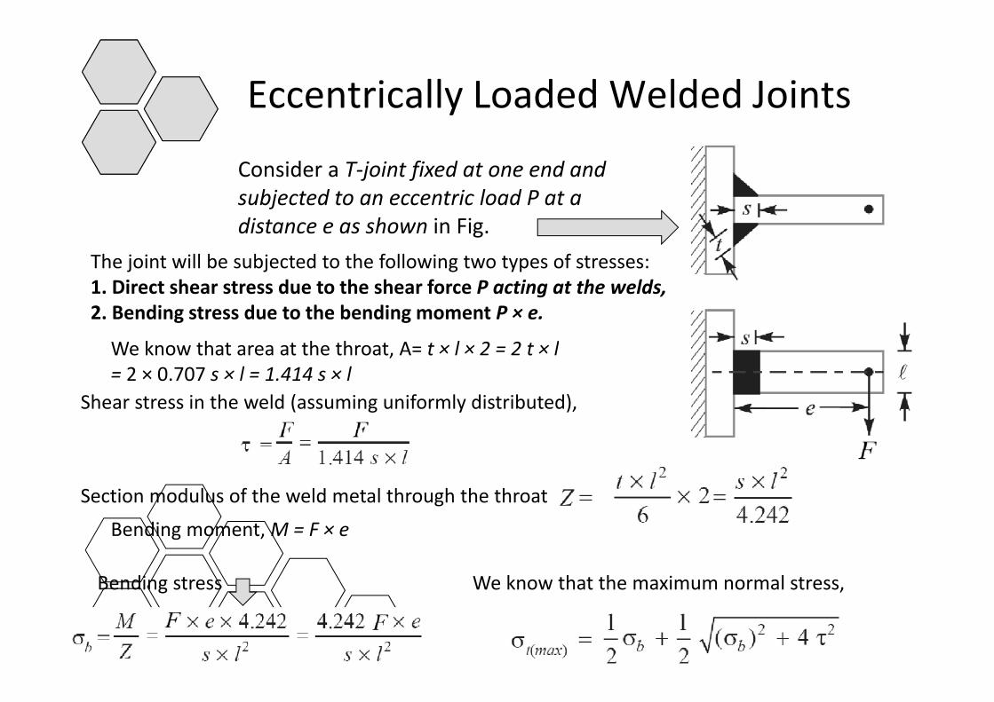
Consider a T‐joint fixed at one end and bj t d t t i l d P tsubjected to an eccentric load P at a
distance e as shown in Fig.The joint will be subjected to the following two types of stresses:j j g yp1. Direct shear stress due to the shear force P acting at the welds, 2. Bending stress due to the bending moment P × e.
We know that area at the throat A= t × l × 2 = 2 t × lWe know that area at the throat, A= t × l × 2 = 2 t × l= 2 × 0.707 s × l = 1.414 s × l
Shear stress in the weld (assuming uniformly distributed),
Section modulus of the weld metal through the throat
Bending moment, M = F × e
Bending stress We know that the maximum normal stress,g ,
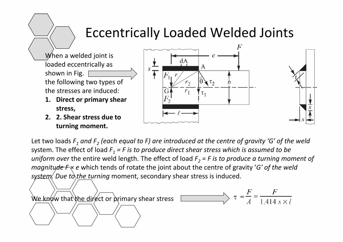
Eccentrically Loaded Welded JointsyWhen a welded joint is loaded eccentrically asloaded eccentrically as shown in Fig. the following two types of the stresses are induced:1. Direct or primary shear
stress, 2. 2. Shear stress due to
turning moment.
Let two loads F1 and F2 (each equal to F) are introduced at the centre of gravity ‘G' of the weldt Th ff t f l d F F i t d di t h t hi h i d t bsystem. The effect of load F1 = F is to produce direct shear stress which is assumed to be
uniform over the entire weld length. The effect of load F2 = F is to produce a turning moment of magnitude F × e which tends of rotate the joint about the centre of gravity ‘G' of the weld system Due to the turningmoment secondary shear stress is inducedsystem. Due to the turning moment, secondary shear stress is induced.
We know that the direct or primary shear stress