WELCOME TO THE LECTURE ON TRANFORMERquickcatchme.yolasite.com/resources/Transformer_CE-165.pdf ·...
74
WELCOME TO THE LECTURE ON TRANFORMER ON TRANFORMER
Transcript of WELCOME TO THE LECTURE ON TRANFORMERquickcatchme.yolasite.com/resources/Transformer_CE-165.pdf ·...
WELCOME TO THE LECTURE ON TRANFORMERON TRANFORMER


Single Phase Transformer Three Phase Transformer

Transformer• A transformer is a stationary
electric machine which transfers electrical energy (power) from one voltage level to another voltage level.
• Unlike in rotating machines, there is no electrical to mechanical energy conversion.
• A transformer is a static device and all currents and voltages are AC.
• The transfer of energy takes place through the magnetic field.

Transformer Principles• It has 2 electric circuits called primary and secondary.
• A magnetic circuit provides the link between primary and secondary.
• When an AC voltage is applied to the primary winding (Vp)of to the primary winding (Vp)of the transformer, an AC current will result (Ip). Ip sets up a time-varying magnetic flux φ in the core.
• A voltage is induced to the secondary circuit (Vs) according to the Faraday’s law of Electromagnetic Induction.(e=MdI/dt)

Transformer
• Transformer is a device that:
ØTransfers electric power from one circuit to another.another.
Ø It does so without a change of frequencyØ It accomplishes this by electromagnetic induction
andØWhere the two circuits are in mutual inductive
influence of each other.

Transformer Core Types• The magnetic (iron) core is
made of thin laminated steel.• The reason of using
laminated steel is to minimizing the eddy current loss by reducing thickness (t):(t):
• 2 common cross section of core is square or rectangular for small transformers and circular (stepped ) for the large and 3 phase transformers.
( )tfBkhPe max=

Transformer Construction• 2 Type of Transformers:1) Core (U/I) Type: is
constructed from a stack of U-and I-shaped laminations. In a core-type transformer, the primary and secondary windings are wound on two different legs of the core.
2) Shell (E/I) Type: A shell-type 2) Shell (E/I) Type: A shell-type transformer is constructed from a stack of E- and I-shaped laminations. In a shell-type transformer, the primary and secondary windings are wound on the same leg of the core, as concentric windings, one on top of the other one.

Elementary Theory of an Ideal Transformer
q For a transformer to be an ideal one, the various assumptions are as follows:
1) Winding resistances are negligible, i.e. no losses.2) There is no magnetic leakage and hence which has 2) There is no magnetic leakage and hence which has
no and core losses. 3) All the flux set up by the primary links the secondary
windings, i.e. all the flux is confined to the magnetic core.
4) The core has constant permeability, i.e. the magnetization curve for the core is linear.
RI 2

Elementary Theory of an Ideal Transformer (cont.)
• Secondary is open and primary is connected to sinusoidal alternation voltage,
• Since secondary is open, the primary draws the magnetizing current only.
• is small in magnitude and lags by .
µI
1V
µI
µI 1V090by .
• The alternating current produces an alternating flux which is proportional to the current and is in phase with it.
• This flux produces self-inducede.m.f. in the primary.
• The self-induced e.m.f. equal to and in opposition to
• is also known as counter e.m.f. or back e.m.f.
1V
1N 2N
2V
Φ
1E 2E
90
Φ
1E1V
1E

Elementary Theory of an Ideal Transformer (cont.)
• Similarly there is produced in the secondary an induced e.m.f. which is known as mutually-inducede.m.f.
• This e.m.f. is anti phase with and its magnitude is proportional to the rate of change of flux and the number of secondary turns.
2E
1V
1V
µI Φ
090
number of secondary turns.• The vectorial representation of the
effective values of the above quantities is shown in the right figure.
µI Φ
1E
2E
090

E.M.F. Equation of a Transformer• =No. of turns in primary• =No. of turns in secondary• =Maximum flux in core in webers• =frequency of a.c. input in Hz• The figure shows flux increases from its zero value
to maximum value in one quarter of the cycle i.e. ¼ second.
1N
2N
mΦf
mΦ
Φ
cycle
1/4f¼ second.• Average rate of change of flux=• Now, rate of change of flux per turn means induced
e.m.f. in volts• Average e.m.f./turn=
• Form factor= = 1.11
• r.m.s. value of e.m.f./turn=
fm
4/1Φ
voltf mΦ4
ueaveragevalvaluesmr ...
mm ff Φ=Φ× 44.4411.1
T=1/fTime
1/4f

• r.m.s. value of the induced e.m.f. in the whole of primary winding=(induced e.m.f./turn)×No.of primary turns
• r.m.s. value of the induced e.m.f. in the whole of secondary
)....(..........44.444.4 111 iANfBNfE mm =Φ=
E.M.F. Equation of a Transformer (cont.)
• r.m.s. value of the induced e.m.f. in the whole of secondary winding=(induced e.m.f./turn)×No.of secondary turns
• From (i) and (ii) we get,
• In Ideal transformer on no-load,
).....(..........44.444.4 222 iiANfBNfE mm =Φ=
mfNN
EE
Φ== 44.42
1
2
1
2211 EandVEV ==

Voltage Transformation Ratio (K)
• This constant K is known as voltage transformation ratio.
KNN
EE
==1
2
1
2
ratio.• (i) If ,then transformer is called step-up
transformer.• (ii) If ,then transformer is called step-down
transformer.
1..12 ⟩⟩ KeiNN
1..12 ⟨⟨ KeiNN
Transformer with Losses but no Magnetic Leakage
q Two cases:(i) Transformer on no-load:
Ø When the transformer in on no-load, the primary input current is not wholly reactive. The primary input current under no-load has to supply, (i) iron loss in the core and (ii) a very small amount of copper loss in (i) iron loss in the core and (ii) a very small amount of copper loss in primary (there being no Cu loss in secondary as it is open).
Ø Hence, the no-load primary input current is not at behind but lags
it by an angle
Ø No-load input power
Ø Where is primary power factor under no-load conditions.
0I 1V090
00 90⟨φ
0010 cosφIVW =
0cosφ

Transformer with Losses but no Magnetic Leakage (cont.)
q No-load condition of an actual transformer is shown vectorially in the figure.
q The primary current has two components:
i. One in phase with . This is known as active or working or iron loss component . It mainly supplies
0i
1V
wI 0φ1V
Icomponent . It mainly supplies the iron loss plus small quantity of primary Cu loss.
ii. The other component is in quadrature with and is known as magnetizing component . Its function is sustain the alternating flux in the core. It is wattless.
µI Φ
1E
2E
w
wI
µI1V
00 sinφIIw =
00 cosφµ II =
220 wIII += µ

Transformer with Losses but no Magnetic Leakage (cont.)
q The following points should be carefully noted:Ø The no-load primary current is very small as compared to the full-load
primary current. It is about 1 percent of the full-load current.Ø Owing to the fact that the permeability of the core varies with the
instantaneous value of the exciting current, the wave of the exciting or magnetizing current is not truly sinusoidal. As such it should not be
0I
represented by a vector because only sinusoidally varying quantities are represented by rotating vectors.But, in practice, it makes no appreciable difference.
Ø As is very small, the no-load primary Cu loss is negligibly small which means that no-load primary input is practically equal to the iron loss in the transformer.
Ø As it is principally the core-loss which is responsible for shift in the current vector, angle is known as hysteresis angle of advance.
0I
0φ

Transformer with Losses but no Magnetic Leakage (cont.)
(ii) Transformer on load:
φφ
2φ
0I
2V
φ'2φ
2φ
φ

Transformer with Losses but no Magnetic Leakage (cont.)
§ When the secondary is loaded, the secondary current is set up.§ The magnitude and phase of , with respect to is determined by the
characteristics of the load. § Current is in phase with if load is resistive, it lags if load is inductive and
it leads if load is capacitive.§ The secondary current sets up its own m.m.f. and hence its own flux which
is opposite to the main primary flux .
2I2I 2V
2I 2V
2ΦΦis opposite to the main primary flux .
§ The secondary amp-turns are known as demagnetizing amp-turns.§ The opposing flux weakens . § gains the upper hand over and hence causes more current to flow in
primary.§ The additional current is known as load component of primary current.§ The additional primary m.m.f. sets up its own flux which is opposition to
and is equal to it in magnitude.§ Hence, the two cancel each other.§ Whatever the load conditions, the net flux passing through the core is
approximately the same as at no-load.
Φ
22IN2Φ Φ
1V 1E
'2I
'2Φ 2Φ

Transformer with Losses but no Magnetic Leakage (cont.)
• Hence, when the transformer is on-load, the
'2122 ININ =∴ 22
1
2'2 KII
NN
I =×=∴'22 Φ=Φ
• Hence, when the transformer is on-load, the primary winding has two currents in it.
• The total primary current is the vector sum ofand
0I'2I
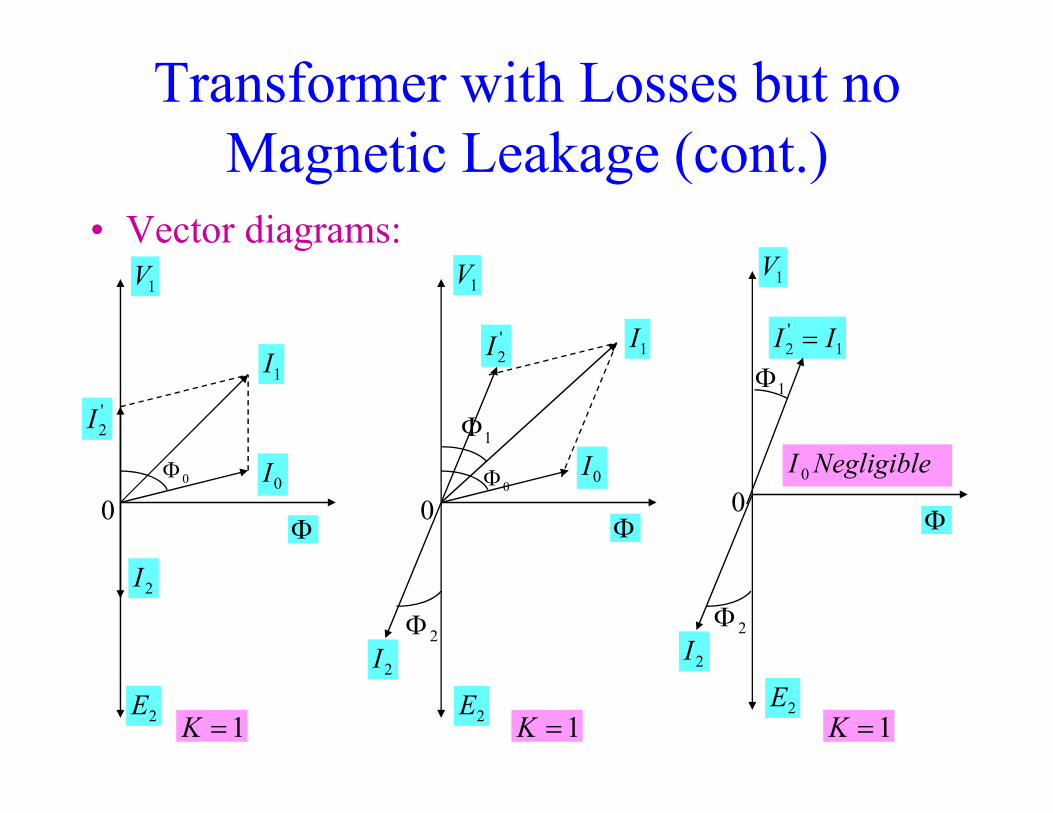
Transformer with Losses but no Magnetic Leakage (cont.)
• Vector diagrams:
'I
1V
1I'2I
1V
1I 1'2 II =
1Φ
1V
0
2I
2E
'2I
0I
Φ
0Φ
1=K
2I
Φ
0I0Φ
1Φ
2E
2Φ
0
1=K
2I
Φ
2E
2Φ
0NegligibleI 0
1=K

Transformer with Losses but no Magnetic Leakage (cont.)
• Under the assumption: is negligible,
ININ = '2112
0I 21 Φ=Φ
KNN
II
II
===⇒1
2
2
1
2
'2

Transformer with winding resistance but no Magnetic Leakage
§ An ideal transformer has no resistance, but an actual transformer has winding resistances.
§ Due to this resistance, there is some voltage drop in the two windings. The result is that:
§ The secondary terminal voltage is vectorially less than the secondary V§ The secondary terminal voltage is vectorially less than the secondary induced e.m.f. by an amount where is the resistance of the secondary winding. Hence, is equal to the vector difference of and resistive voltage drop .
§ Similarly, primary induced e.m.f. is equal to the vector difference of and where is the resistance of the primary winding.
2V2E 22RI 2R
2V 2E22RI
1E 1V11RI 1R
2222 RIEV −=
1111 RIVE −=

Transformer with winding resistance but no Magnetic Leakage (cont.)
1E−
11RI11RI
1E−
'2I
1V
1I'2I
1V
1I
1Φ
1E−
1V
1I
11RI
1Φ
22RI
0
2I
2E
2
2
KI
I
=0I
Φ
0Φ
2I
Φ
0I0Φ
2E
2Φ
0
2V
Non-inductive
2V
Inductive
'2I
Φ
0I
2E
2I2V
22RI
Capacitive
2Φ
0

Resistance of a Transformer
qA transformer whose primary and secondary windings have resistances of and respectively is shown in the figure.
R
1R 2R
1R 2R

Magnetic Leakageq Leakage Flux: Not all of the flux
produced by the primary current links the winding, but there is leakage of some flux into air surrounding the primary.
q Similarly, not all of the flux produced by the secondary current (load current) links the secondary, rather there is loss of flux due to leakage.
and 1
11 I
eX L=2
22 I
eX L=
q These effects are modeled as leakage reactance in the equivalent circuit representation.
q A transformer with magnetic leakage is equivalent to an ideal transformer with inductive coils connected in both primary and secondary circuits as shown in the next slide.
q The internal e.m.f. in each inductive coil is equal to that due to the corresponding leakage flux in the actual transformer.

Transformer with Magnetic Leakage§ Important points:
– The leakage flux links one or other winding but not both, hence it in no way contributes to the transfer of energy from the primary to the secondary winding.
– The primary voltage will have to supply reactive drop in addition to .
Similarly, will have to supply and .– In an actual transformer, the primary and secondary windings are not placed on
separate legs or limbs as shown below because due to their being widely separated,
1V 11XI 11RI
2E 22RI 22XI
large primary and secondary leakage fluxes would result.

Transformer with Resistance and Leakage Reactance
1Z2Z
qThe primary impedance:qThe secondary impedance:qThe Voltage drops:
( )21
211 XRZ +=
( )22
222 XRZ +=
( ) 222222222 ZIVjXRIVE +=++=( ) 1111
21111 ZIEjXRIEV +=++=

Vector diagram of Actual Transformer
11ZI11ZI
11ZI
22ZI22ZI
22ZI

Transfer of resistances & reactances to any side

Transfer of resistances & reactances to any side (cont.)

Transfer of resistances & reactances to any side (cont.)

Transfer of resistances & reactances to any side (cont.)
Impedance referred to primary
01R 01X
01Z
Impedance referred to primary
Impedance referred to secondary

Equivalent Circuit of a Transformer

Equivalent circuit of a Transformer referred to primary/Exact Equivalent circuit
• Where, and = impedance of the exciting circuit
( )''21 Lm ZZZZZ ++= ( )
( )
+++
+= ''2
''2
1Lm
Lm
ZZZZZZ
Z
'2
'2
'2 jXRZ += mZ
( )( )
+++
+×= ''2
''2
111Lm
Lm
ZZZZZZ
ZIV
22
'2
22
'2
22
'2 ,, KZZKXXKRR === KVVEKEE 2
'212
'2 , ===

Approximate Equivalent Circuit • Transfer exciting circuit as shown in figure:

Approximate Equivalent circuit with secondary impedances transferred to primary

Equivalent Circuit (cont.)• Neglecting the exciting circuit:
'21 II =
01R 01X
01Z
'LZ2V

Why Transformer Rating in kVA?
ØCu loss of a transformer depends on current.Ø Iron loss of a transformer depends on voltage.ØHence, total transformer loss depends on volt-ØHence, total transformer loss depends on volt-ampere (VA) and not on phase angle between voltage and current i.e.total transformer loss is independent of load power factor.
ØThat’s why transformer rating is in kVA and not in kW.

Percentage Resistance, Reactance and Impedance
Ø Usually measured by the voltage drop at full-load current.
i. Percentage resistance at full-load:
100%1
011 ×=VRI
R
%R=%Cu Loss at full-load%R=%Cu Loss=
100%
100%
22
0222
11
012
1
1
×=⇒
×=⇒
IVRI
R
IVRI
R
V
rv

Percentage Resistance, Reactance and Impedance (cont.)
ii. Percentage reactance at full-load:
xvVXI
X
VXI
X
=×=⇒
×=
100%
100%
022
1
011
iii. Percentage impedance at full-load:
iv. So,
xV2
100%
100%
2
022
1
011
×=⇒
×=
VZI
Z
VZI
Z
( )22 %%% XRZ +=

Percentage Resistance, Reactance and Impedance (cont.)
• Now, Similarly,
• Now, Similarly,100
%100
%
100%
1
1
1
101
1
011
××
=××
=⇒
×=
IVCuLoss
IVR
R
VRI
R
100%
100%
100%
2
2
2
202
2
022
××
=××
=⇒
×=
IVCuLoss
IVR
R
VRI
R
100% 011 ×=XI
X 100% 022 ×=XI
X• Now, Similarly,
Ø Percentage resistance, reactance and impedance have the same value whether referred to primary or secondary.
100100%
100%
1
1
1
101
1
011
××
=××
=⇒
×=
IVv
IVX
X
VXI
X
x
100100%
100%
2
2
2
202
2
022
××
=××
=⇒
×=
IVv
IVX
X
VXI
X
x
Losses in a Transformerq Two types of losses
i. Core or Iron Loss:Ø It includes both hysteresis and eddy current loss. Because the
core flux in a transformer remains practically constant for all loads. The core is practically same at all loads.
Hysteresis Loss = watt; fVBW 6.1η=Hysteresis Loss = watt; Eddy current Loss = watt.Ø These losses are minimized by using steel of high silicon
content for the core and by using very thin laminations.Ø Iron or Core loss is found from the Open Circuit test.Ø The input of the transformer when on no-load measures the
core loss.
fVBWh6.1
maxη=222
max tfPBWe =

Losses in a Transformer (cont.)
ii. Copper Loss:Ø This loss is due to the ohmic resistance of the
transformer windings.Ø Total Cu loss=Ø Total Cu loss=Ø So, Cu loss is proportional to orØ Cu loss is found from the short-circuit test.
022201
212
221
21 RIRIRIRI ==+
( )2current ( )2kVA

Efficiency of a Transformer
IronLossCuLossOutputOutput
LossesOutputOutput
++=⇒
+=
η
η
Ø Efficiency is based on power output in watts and not in volt-amperes, although losses are proportional to VA.
Ø Thus, efficiency depends on power factor and maximum at a power factor of unity.
InputLosses
InputLossesInput
−=−
= 1η

Condition for Maximum EfficiencyØ Cu Loss = Ø Iron Loss = hysteresis loss + eddy current loss =Ø Primary Input =
111 φCosIV
111
φφηCosIV
LossesCosIV −=
012
1 RIiW
11111
011
111111
012
1
111
012
1111
111
1
1
φφη
φφη
φφ
η
φ
CosIVW
CosVRI
CosIVW
CosIVRI
CosIVWRICosIV
CosIV
i
i
i
−−=⇒
−−=⇒
−−=⇒

Condition for Maximum Efficiency (cont.)
» or
» Therefore, »» The output current corresponding
to maximum efficiency isi
i
i
CosIVW
CosVR
CosIVW
CosVR
dId
CosIVW
CosVRI
dId
dId
+−=⇒
+−=⇒
−−=
201
12
1111
01
1
11111
011
11
00
0
1
φφ
φφη
φφη iWIR =2
202
Cu loss= Iron Loss
( )RWI =
i
i
i
WIR
IW
R
CosIVW
CosVR
CosIVCosV
=⇒
=⇒
=⇒
2101
21
01
12
1111
01
12
1111
φφ
φφ ( )022 RWI i=

All-day Efficiency
• The distribution transformer have their primaries energized all the twenty-four hours, although their secondaries supply little or no-load much of the time during the day except during the house lighting period.
• The core loss occurs throughout the day, the Cu loss occurs only when • The core loss occurs throughout the day, the Cu loss occurs only when
the transformer is loaded.
=−dayallηOutput in kWhInput in kWh
(for 24 hours)
All day efficiency Large capacity transformers used in power systems are classified broadly into Power trans- formers and Distribution transformers. The former variety is seen in generating stations and large substations. Distribution transformers are seen at the distribution substations. The basic difference between the two types arise from the fact that the power transformers are switched in or out of the circuit depending upon the load to be handled by them. Thus at 50% load on the station only 50% of the transformers need to be connected in the circuit. On the other hand a distribution transformer is never switched off. It has to remain in the circuit irrespective of the load connected. In such cases the constant loss of the transformer continues to be dissipated. Hence the concept of energy based efficiency is defined for such transformers. It is called ’all day’ efficiency. The all day efficiency is thus the ratio of the energy output of the transformer over a day to the corresponding energy input.

Examples
qEx-1: (a) A 2,200/200 V transformer draws a no-load primary current of 0.6 A and absorbs 400 watts. Find the magnetizing and iron loss currents. currents.
(b) A 2200/250 V transformer takes 0.5 A at p.f. of 0.3 on open circuit. Find magnetizing and working components of no-load primary current.
ExamplesqEx-2: A transformer has a primary winding of
800 turns and a secondary winding of 200 turns. When the load current on the secondary is 80A at 0.8 power factor lagging, the primary current is 25A at 0.707 power factor lagging. is 25A at 0.707 power factor lagging. Determine the no-load current of the transformer and its phase.

ExamplesqEx-3: A 30 kVA, 2400/120-V, 50Hz
transformer has a high voltage winding resistance of 0.1Ω and a leakage reactance of 0.22Ω. The low voltage winding resistance is 0.035Ω and the leakage reactance is 0.012Ω. 0.035Ω and the leakage reactance is 0.012Ω. Find the equivalent winding resistance, reactance and impedance referred to the (i) high voltage side and (ii) the low-voltage side.

ExamplesqEx-4: In a 25 kVA, 2000/200-V, single phase
transformer, the iron and full-load Cu losses are 350W and 400W, respectively. Calculate the efficiency at unity power factor on (i) full-load, (ii) half full-load.(ii) half full-load.

Parallel Operation of a Single Phase Transformer
q Conditions:1. Primary winding of a transformer should be suitable for the
supply system voltage and frequency.2. The transformer should be properly connected with regard to
polarity.3. The voltage ratings of both primaries and secondaries should be 3. The voltage ratings of both primaries and secondaries should be
identical.In other words, the transformers should have the same turn ratio i.e. transformation ratio.
4. The percentage impedance should be equal in magnitude and have the same X/R ratio in order to avoid the circulating currents and operation at different power factors.
5. With transformers having different kVA ratings, the equivalent impedances should be inversely proportional to the individual kVA rating if circulating currents are to be avoided.

Transformer Parallel Connection
AV1 V2+
-
+
-
B
-
+ +
-
- -

Transformer Parallel Operation v Case 1:Ideal CaseØ Two transformers having the same voltage ratio.Ø Impedance voltage triangles are identical in size and shape.
C
ZAIA
A
B
CE
V2IA
IB
I
ф0
EE
IA
IB
ZB
Loa
d
I
V2
V1

Transformer Parallel Operation (cont.)
;
;BA
IZEZIEZIEV
III
−=−=−=
+=
)();(
;
,
;2
BAABBABA
ABBA
BBAA
ABBBAA
ZZZIIZZZII
ZZII
ZIZIAlso
IZEZIEZIEV
+=+=
=⇒
=
−=−=−=

Transformer Parallel Operation (cont.)v Case 2:Equal Voltage RatiosØ Two transformers having the same voltage ratio.Ø Impedance voltage triangles are different in size and shape.Ø No-circulating current.
ZAI
V2
IA
IB
I
ф0
EB
EA
IA
IB
ZB
Loa
dI=IA+IB
V2
V1

Transformer Parallel Operation (cont.)
• Multiplying both sides by V ,
)();(
;
;
BAABBABA
ABBA
BBAA
BA
ZZZIIZZZII
ZZII
ZIZI
III
+=+=
=⇒
=
+=
• Multiplying both sides by V2,
• Where, V2I×10-3 =S-the combined load kVA.BA
BA
BA
BA
ZZZ
SS
ZZZ
IVIV
+=⇒
+= 22
BA
AB
BA
AB
ZZZ
SS
ZZZ
IVIV
+=⇒
+= 22

Transformer Parallel Operation (cont.)v Case 3:Unequal Voltage RatiosØ Two transformers having different voltage ratio.Ø Impedance voltage triangles are different in size and shape.Ø Circulating current.
B
C
ZAI C
V2
IA
IB
I
ф0
EB
EA
IA
IB
ZB
Loa
dI=IA+IB
V2
V1

Transformer Parallel Operation (cont.)
( )[ ] ;
;
);.....()(
;)(
;)(
;;
2
22
BBAABA
LBABBB
LBAAAA
LBAL
BBBAAA
ZZIEEI
ZIZIEE
iiiZIIZIE
ZIIZIE
ZIIIZV
VZIEVZIE
+−=
−=−
++=
++=
+==
+=+=
• Substituting this value in eqn (iii)( )[ ] ;ABBBAA ZZIEEI +−=
( ) [ ]( )[ ] ( )[ ]( )[ ] ( )[ ]
( )BALBA
ABBABA
BALBALBABAA
BALBALBAABB
LBABBBABBB
ZZZZZZEZE
III
ZZZZZZEEZEI
ZZZZZZEEZEI
ZIZZIEEZIE
+++
=+=
++−+=
++−−=
++−+=
;
;
;
( )
BA
BAC
LBALBA
ABBA
L
ZZEE
I
ZZZZZZ
ZEZE
IZV
+−
=
+++
=
=2

Transformer Test

Open Circuit Test

Short Circuit Test
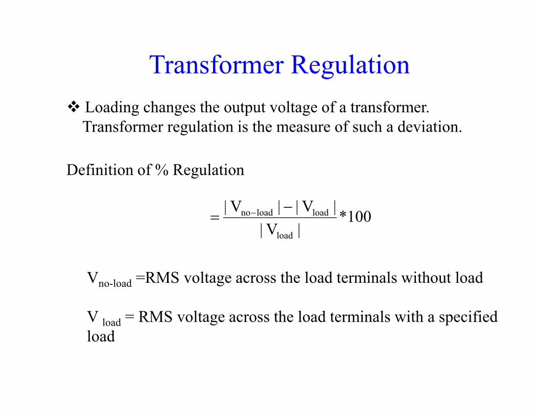
Transformer Regulationv Loading changes the output voltage of a transformer.
Transformer regulation is the measure of such a deviation.
Definition of % Regulation
100*|V||V| loadloadno −
= − 100*|V|
|V||V|
load
loadloadno −= −
Vno-load =RMS voltage across the load terminals without load
V load = RMS voltage across the load terminals with a specifiedload

Auto Transformerv It is a transformer with one winding only, part of it been
common to both primary and secondary.v Primary and Secondary winding are not electrically isolated
from each other.v Its theory and operation are similar to that of a two winding
transformer.transformer.v Because of one winding it is compact, efficient and cheaper.v It is used where transformation ratio differs little from unity.v It is also used as an adjustable transformer for both stepping
up and stepping down the input voltage.

Auto Transformer (cont.)
Step up Auto transformer
Step down Auto transformer
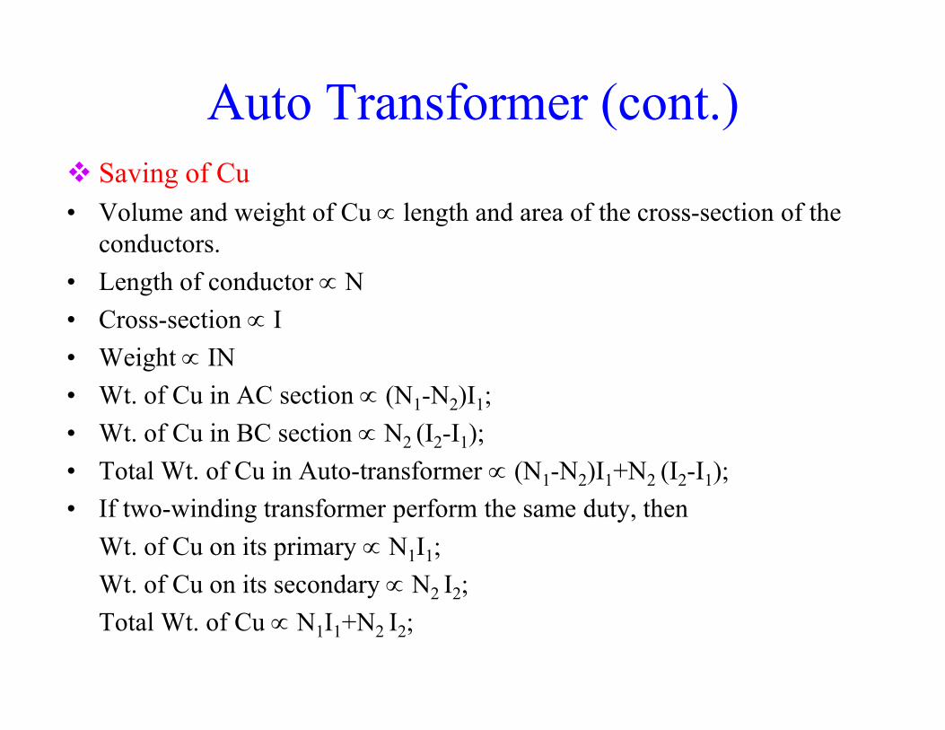
Auto Transformer (cont.)v Saving of Cu• Volume and weight of Cu ∝ length and area of the cross-section of the
conductors.• Length of conductor ∝ N• Cross-section ∝ I• Weight ∝ IN• Weight ∝ IN• Wt. of Cu in AC section ∝ (N1-N2)I1;• Wt. of Cu in BC section ∝ N2 (I2-I1);• Total Wt. of Cu in Auto-transformer ∝ (N1-N2)I1+N2 (I2-I1);• If two-winding transformer perform the same duty, then
Wt. of Cu on its primary ∝ N1I1; Wt. of Cu on its secondary ∝ N2 I2;Total Wt. of Cu ∝ N1I1+N2 I2;

Auto Transformer (cont.)
Wt. of Cu in Auto-transformer Wt. of Cu in ordinary transformer
( ) ( )2211
122121
ININIININN
+−+−
=
KK
INNN
−=−=×+
−= 12
211
21
22
1
2
So, Saving of Cu
Saving of Cu
( ) Oa WKW
II
NN
−=⇒
×+
1
211
2
1
2
OOOaO KWWKWWW =−−=−= )1(
OKW=

ExamplesqEx-5: A 5 kVA, 2300/230-V, 50Hz transformer
was tested for the iron losses with normal excitation and Cu losses at full-load and these were found to be 40W and 112W,respectively. Calculate the efficiency of the transformer at Calculate the efficiency of the transformer at 0.8 power factor for 1.25kVA outputs.
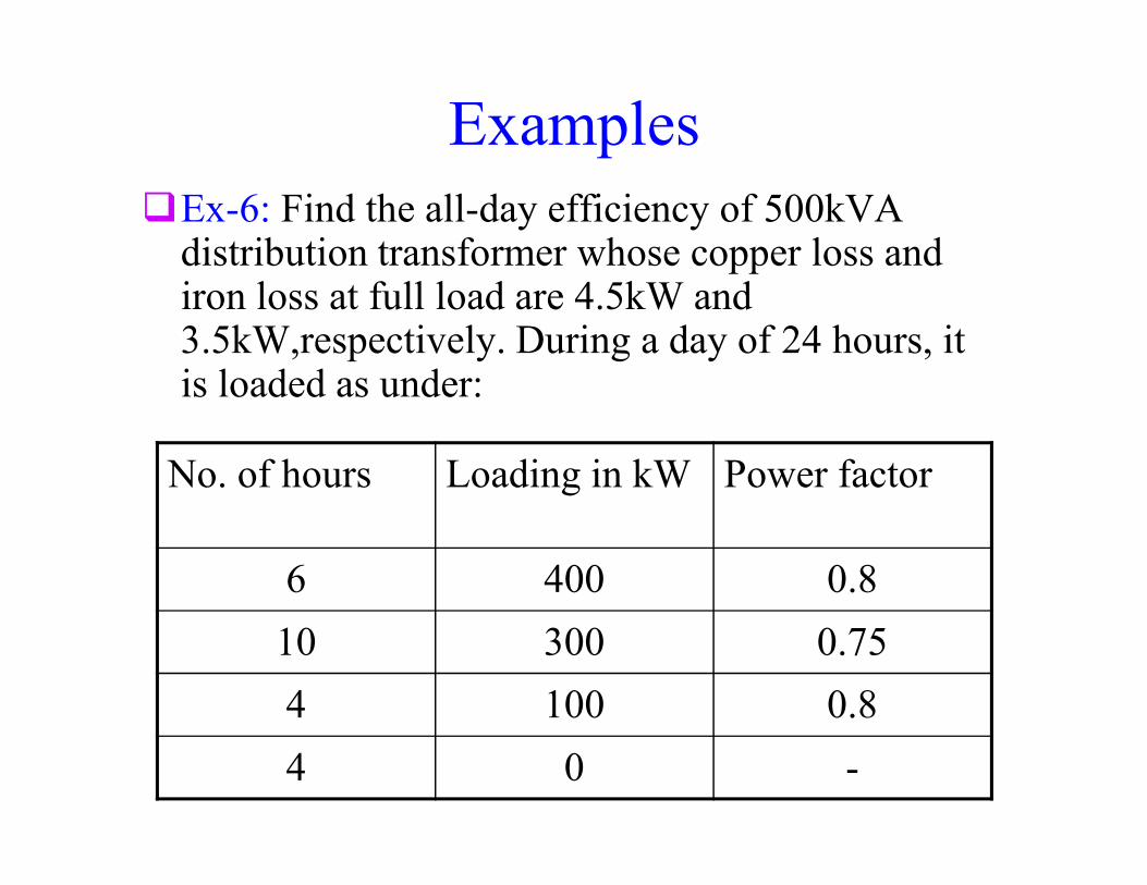
ExamplesqEx-6: Find the all-day efficiency of 500kVA
distribution transformer whose copper loss and iron loss at full load are 4.5kW and 3.5kW,respectively. During a day of 24 hours, it is loaded as under:
No. of hours Loading in kW Power factor
6 400 0.8
10 300 0.75
4 100 0.8
4 0 -

Examples
q Ex-7: A 600kVA, 1-ph transformer has an efficiency of 92% both at full-load and half-load at unity power factor. Determine its load at unity power factor. Determine its efficiency at 60% of full-load at 0.8 power factor lag.

Examples
q Ex-8: Ex: Two 1-ph transformers with equal turns have impedances of (0.5+j3) ohm and (0.6+j10) ohm with respect to the ohm and (0.6+j10) ohm with respect to the secondary. If they operate in parallel, determine how they will share a total load of 100 kW at p.f. 0.8 lagging?

Examples
q Ex-9: Ex: Two 2200/110-V, transformers are operated in parallel to share a load of 125kVA at 0.8 power factor lagging. Transformers are at 0.8 power factor lagging. Transformers are rated as below:A:100 kVA;0.9% resistance and 10% reactance.B:50 kVA;1.0% resistance and 5.0% reactance.
Find the load carried by each transformer.
Examples
q Ex-10: Ex: Two transformers A and B are operated in parallel to the same load. Determine the current delivered by each transformer having the current delivered by each transformer having given: open-circuit e.m.f. 6600V for A and 6400V for B. Equivalent leakage impedance in terms of the secondary = 0.3+j3 for A and 0.2+j1 for B.The load impedance is 8+j6.