Welcome to the EPTAC Webinar Series: Defects: Lead ... · 1 Welcome to the EPTAC Webinar Series:...
21
1 Welcome to the EPTAC Webinar Series: Defects: Lead Protrusion & Damaged Pins You are connected to our live presentation delivered via the internet. The webinar will begin shortly. You will see the presentation slides on your computer monitor. To hear the audio, you must use a telephone. For Audio: Please use a telephone and call: (605) 772-3434 Enter access code: 349-072-792
Transcript of Welcome to the EPTAC Webinar Series: Defects: Lead ... · 1 Welcome to the EPTAC Webinar Series:...

1
Welcome to the EPTAC Webinar Series:Defects: Lead Protrusion & Damaged Pins
You are connected to our live presentation delivered via the internet. The webinar will begin shortly.
You will see the presentation slides on your computer monitor. To hear the audio, you must use a telephone.
For Audio: Please use a telephone and call: (605) 772-3434Enter access code: 349-072-792

2
Attendee Quick Reference
Control Panel Features:Once you have joined our Webinar, you will see this GoToWebinar Control Panel and Grab Tab. The control panel contains three panes that can be expanded or collapsed by clicking the arrow on the left side of each pane.
To Leave a Webinar:1. From the Attendee Control Panel File Menu, select Exit – Leave Webinar.2. On the Leave Webinar?Confirmation dialog box, click Yes.
You can ask questions by typing text directly to the presenter using the “Question and Answer” box
Defects:Lead Protrusion
andDamaged Pins

4
Question
What’s the criteria for lead protrusion?
Does it impact lead clinching?
What does violate minimum Electrical Spacing mean?
5
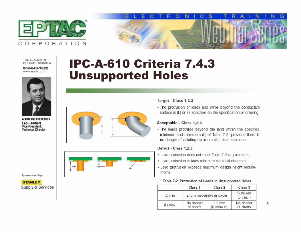
IPC-A-610 Criteria 7.4.3 Unsupported Holes
6
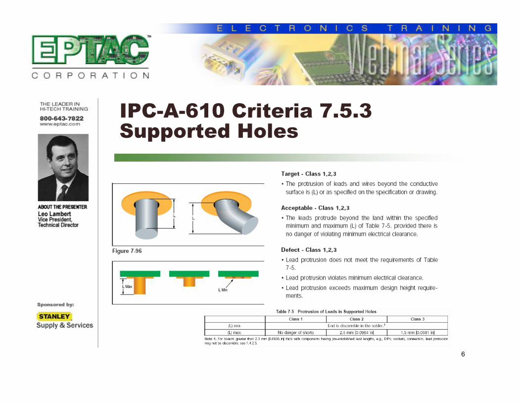
IPC-A-610 Criteria 7.5.3 Supported Holes
7
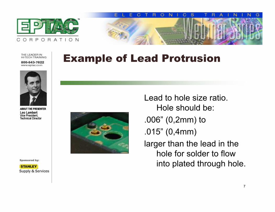
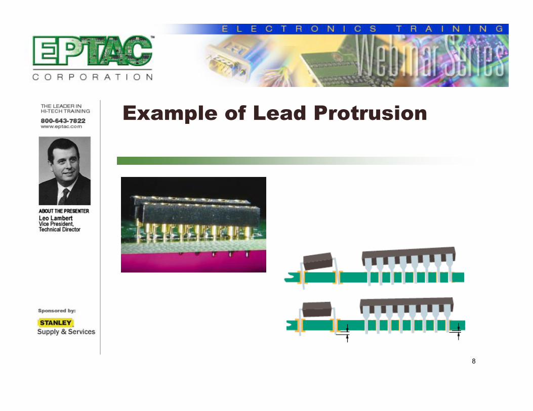
Example of Lead Protrusion
Lead to hole size ratio. Hole should be:
.006” (0,2mm) to
.015” (0,4mm)
larger than the lead in the hole for solder to flow into plated through hole.
8
Example of Lead Protrusion

9
Lead Clinching

10
Minimum Electrical Spacing

Damaged Pins and Connectors
12
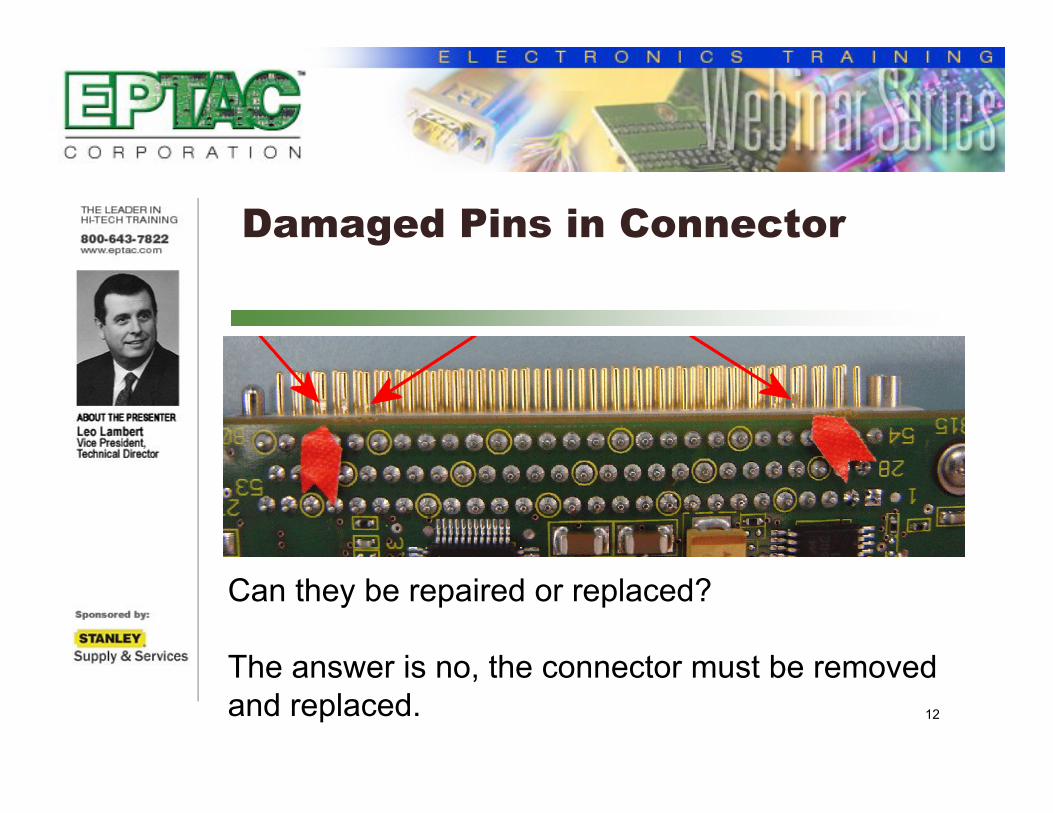
Damaged Pins in Connector
Can they be repaired or replaced?
The answer is no, the connector must be removed and replaced.
13
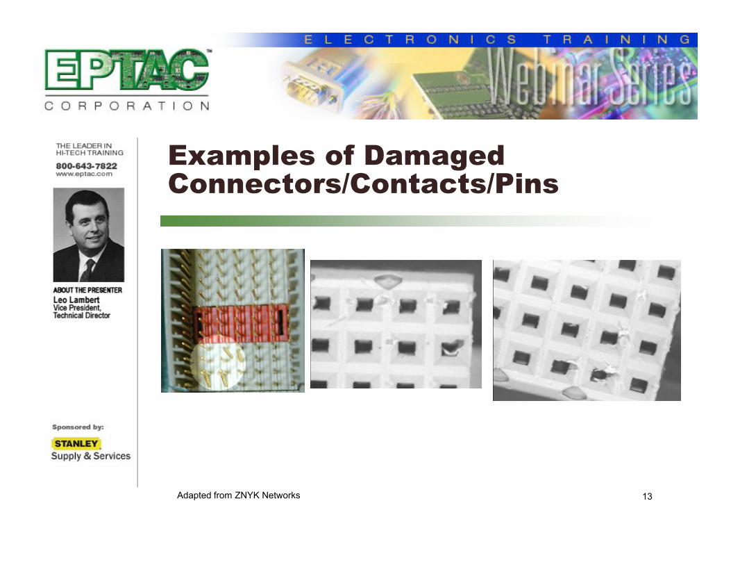
Examples of Damaged Connectors/Contacts/Pins
Adapted from ZNYK Networks

14
Examples of Damaged Connectors/Contacts/Pins
Acceptable – Class 1
Process Indicator – Class 2, 3
Connector face has been chipped but dielectric between seals is intact.
Chipping does not extend from one cavity to the outer diameter of any adjacent cavity.
Extrapolated from IPC/WHMA/A-620

15
Examples of Damaged Connectors/Contacts/Pins
Defect – Class 1,2,3 Chipping of the dielectric
extends from cavity to the outside diameter of any adjacent cavity.
Crack extends from one cavity to another.
Extrapolated from IPC/WHMA/A-620

16
Examples of Damaged Connectors/Contacts/Pins
Defect – Class 1, 2, 3
Damaged contact.
Contact is bent.
Extrapolated from IPC/WHMA/A-620
17
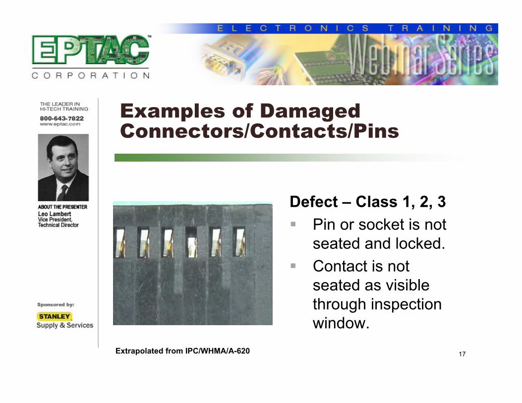
Examples of Damaged Connectors/Contacts/Pins
Defect – Class 1, 2, 3
Pin or socket is not seated and locked.
Contact is not seated as visible through inspection window.
Extrapolated from IPC/WHMA/A-620

18
Examples of Damaged Connectors/Contacts/Pins
Extrapolated from IPC-A-610
19
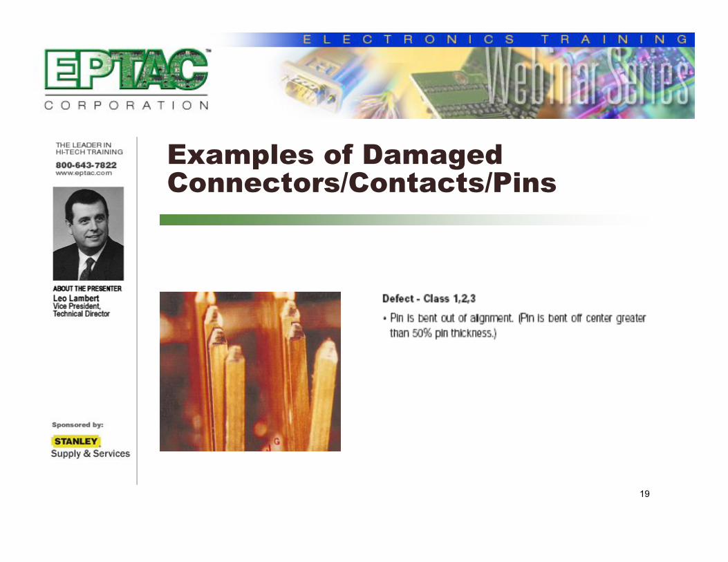
Examples of Damaged Connectors/Contacts/Pins

20
Upcoming . . .
January 17th
Manually Reflowing Solder Paste --Yes or No -- and Our Recommendations

21
Further Information
For questions regarding this webinar, please contact Leo Lambert at
For information on any of EPTAC’s or IPC’s Certification Courses, please visit our
website at http://www.eptac.com