Welcome to ABC-Products
28
Instruction manual Movie Tech AG / ABC-Products Martin-Kollar-Str. 9 81829 Munich Germany Tel. +49 (0)89 43 68 91 3 Fax. +49 (0)89 43 68 91 55 Movie Tech S.r.l. / ABC-Products Viale Edison 318 20099 Milano Italy Tel. +39 (0)2 22470043 Fax. +39 (0)2 24410163 www.abc-products.de e-mail: [email protected]
Transcript of Welcome to ABC-Products
Instruction manual
Movie Tech AG / ABC-Products Martin-Kollar-Str. 9 81829 Munich Germany Tel. +49 (0)89 43 68 91 3 Fax. +49 (0)89 43 68 91 55
Movie Tech S.r.l. / ABC-Products Viale Edison 318 20099 Milano Italy Tel. +39 (0)2 22470043 Fax. +39 (0)2 24410163
www.abc-products.de
e-mail: [email protected]

Welcome to ABC-Products
Our vision ist to help our customers achieve the moving shot with any type of camera in any situation. This is a challenge that we are pleased to pursue and that we can only master with constant feedback from our customers.
We wish you great pleasure using our products.

APR07
www.abc-products.de … wherever you go 3
Overview We congratulate you on your purchase of the HandyMan G-Force pro.
It was specifically developed for demanding users. Without compromise in every detail, the G-Force is particularly well-suited for use in the area of MiniDV, DV and HD(V) camcorders.
The HandyMan G-Force integrates seamlessly into the comprehensive ABC assortment and can be combined with components of existing products.
Adjustable post
With the precision mechanism, the side-to-side module can be continuously adjusted in two axes. A stop module provides the necessary security for the camera.
The power supply makes it possible to use various auxiliary devices such as camera lights. Three BNC connections make it possible to connect an HD monitor (optional).
Spring arm
Two independent spring systems perfectly balance the movements of the operator. The lightweight design and extremely compact dimensions of the spring arm are impressive and ensure the desired maneuverability.
And, the spring tension can be steplessly adjusted. Vest
The completely redesigned G-Force vest defines new standards. The light, but torsion-resistant aluminum plate can be fitted to nearly any body size. Chest and shoulder belts can be variably adjusted in the position. The spring arm mount can be moved up or down.
The multi-part pad elements can be individually positioned and are washable. A double aluminum profile in S shape, which can also be fitted in the back, ensures that loads on the spinal column are properly distributed. And, air ducts make wearing the vest noticeably more comfortable.

APR07
www.abc-products.de … wherever you go 4
Contents (English)
Overview ..................................................................................................................................................................... 3
Contents (English) ........................................................................................................................................................ 4
Package contents ......................................................................................................................................................... 5
Overview of the G-Force pro sled.................................................................................................................................. 7
Overview of the G-Force pro vest.................................................................................................................................. 8
Overview of the G-Force pro connections ...................................................................................................................... 9
Overview of the G-Force pro monitor.......................................................................................................................... 10
HandyMan: G-Force Pro ............................................................................................................................................. 11
General safety instructions: ................................................................................................................................... 11
Technical data: ...................................................................................................................................................... 12
Installation and mounting .......................................................................................................................................... 13
Setting up the trim tripod with trim plate ............................................................................................................... 13
Mounting the monitor on the monitor holder ......................................................................................................... 15
Mounting the monitor holder with monitor on the post ........................................................................................... 15
Mounting the battery ............................................................................................................................................ 15
Mounting the camcorder........................................................................................................................................ 15
Mounting the camcorder........................................................................................................................................ 16
Trimming the system.................................................................................................................................................. 17
Swinging the sled .................................................................................................................................................. 18
Putting on the vest ................................................................................................................................................ 19
Setting the height adjustment for the spring arm / changing the left/right sled guide............................................. 21
Setting the adjustment angle ................................................................................................................................. 21
Mounting the spring arm....................................................................................................................................... 22
Mounting the sled to the spring arm ...................................................................................................................... 23
Hand posture and guiding the sled ........................................................................................................................ 23
Adjusting the spring arm ....................................................................................................................................... 24
Testing the trimming ............................................................................................................................................. 24
Low mode............................................................................................................................................................. 25
Mounting the "Hoodman" anti-glare device ............................................................................................................ 26
Optional accessories ................................................................................................................................................... 27
Mounting the bubble level, item no. 821497 ......................................................................................................... 27
Mounting the digital voltage indicator, item no. 821481 ........................................................................................ 27
Sandbag for weighting the tripod, item no. 832100............................................................................................... 27
APR07
www.abc-products.de … wherever you go 5
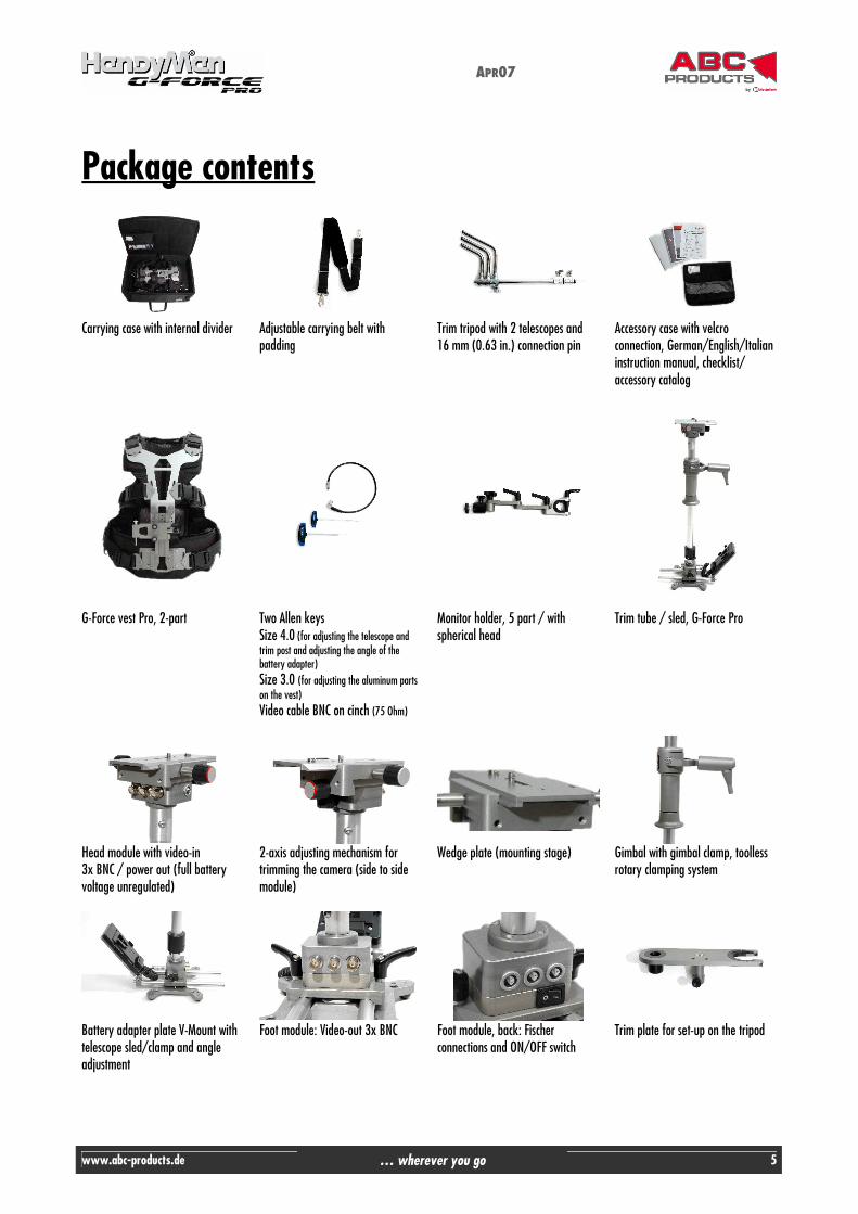
Package contents
Carrying case with internal divider
Adjustable carrying belt with padding
Trim tripod with 2 telescopes and 16 mm (0.63 in.) connection pin
Accessory case with velcro connection, German/English/Italian instruction manual, checklist/ accessory catalog
G-Force vest Pro, 2-part
Two Allen keys Size 4.0 (for adjusting the telescope and trim post and adjusting the angle of the battery adapter) Size 3.0 (for adjusting the aluminum parts on the vest) Video cable BNC on cinch (75 Ohm)
Monitor holder, 5 part / with spherical head
Trim tube / sled, G-Force Pro
Head module with video-in 3x BNC / power out (full battery voltage unregulated)
2-axis adjusting mechanism for trimming the camera (side to side module)
Wedge plate (mounting stage)
Gimbal with gimbal clamp, toolless rotary clamping system
Battery adapter plate V-Mount with telescope sled/clamp and angle adjustment
Foot module: Video-out 3x BNC
Foot module, back: Fischer connections and ON/OFF switch
Trim plate for set-up on the tripod

APR07
www.abc-products.de … wherever you go 6
Stand with rubber feet
A) Monitor B) Monitor case C) Anti-glare device ("Hoodman")
Monitor video power cable (MiniDin 6-pin to Fischer 4-pin)
G-Force double spring arm Scale for the travel of the spring arm (0 = low pretension with low camera weight) (3 = high pretension with high camera weight)

APR07
www.abc-products.de … wherever you go 7
Overview of the G-Force pro sled
Fine leveling control for perfect taring in the side-to-side module Traverse sled with safety function
Large diameter hand grip for precise control
Toolless clamping system on the gimbal for quick set-up 7"- TFT LCD monitor
(16:9/4:3, Pal/NTSC) DC 12 V power cable
Spherical head for turning the monitor 360 degrees / easy low mode
Connection sockets 3 x BNC in for HD
1 x power out
Precision ball bearing
Ergonomic design supports the vertical swivel movements
Telescopic post - system length up to 340 mm (13.39 in.)
Adjustable battery holder angle 180 degrees for
Sony V-Mount Optional: Anton Bauer
NP 1 & voltage indicator
Multi-variable monitor holder with toolless adjustment for universal positioning
Stepless battery adjustment (toolless) - for extremely compact size of the system Horizontal travel of max. 185 mm (7.28 in.)
Base plate with various mounting threads and stable jack stands
Connection sockets: 1 x video + power out 12 Volt
3 x BNC for HD 1 x power out
1 x power in

APR07
www.abc-products.de … wherever you go 8
Overview of the G-Force pro vest
High-strength clasps, durable, resistant to deformation
Adjustment function for perfect shoulder width adjustment
Length of the fastening belts can be flexibly adjusted
Mount for double spring arm, made of steel
Travel for spring arm angle +/- 20 degrees
Tough Cordura material
Best fit Interior padding can be
individually fitted to the body
Adjustment function for perfect chest belt
adjustment
Adjustable front plate for length adjustment,
travel up to 70 mm (2.76 in.)
Air-System-Pro Padding with air ducts for optimal
comfort
S-Ergotech Aluminum back shaping in S form for perfect spinal column support function
Stepless height adjustment of the spring arm, travel: 160
mm (6.30 in.)

APR07
www.abc-products.de … wherever you go 9
Overview of the G-Force pro connections
Head module: Video-in 3x BNC Lateral power out (full battery voltage unregulated) Connection for XLR to 2-pin Fischer via spiral cable to external power supply from camcorders or similar (max. 25 watt)
Foot module: Video-out 3x BNC
A) Fischer 4-pin jack 12V, regulated (deactivatable) B) Power in/out Fischer, 2-pin (battery voltage) C) and B) Connection options for battery current supply or LCD voltage indicator (see Accessories) D) Main power on/off switch

APR07
www.abc-products.de … wherever you go 10
Overview of the G-Force pro monitor
To call up the menu and to make any changes, press the Menu button and navigate to the desired sub-menu by using the -/+ buttons. Press the Menu button to activate your selection. See an overview of possible sub-menus in the graphic to the left. Technical data: Screen size: 7" (17.78 cm) Display format: 16:9 Power consumption: 8.5 watt Power supply: DC 12 Volt Brightness: 300 nits System: PAL/NTSC Resolution: 480 x 234 Operating temperature: 0 ° to approx. 50 °C (32 ° to approx. 122 °F)
Menu buttons
Power button and power LED
Format switch (4:3 or 16:9)
Mirror function Video source toggle switch
Ext. audio/video input, headphone output (ext. wired only)

APR07
www.abc-products.de … wherever you go 11
HandyMan: G-Force Pro
General safety instructions:
1) Set up the trim tripod on a solid surface and secure with sandbags if necessary.
2) Using the fixing screw, secure the camera base plate to the camcorder.
3) Mount the camera wedge plate true to side - it can otherwise lead to gear rack damage.
4) During each trim procedure, open the bleeder screws, trim the tripod, secure the bleeder screws.
5) Operating the device stresses the muscles of the back among other things. Please allow for sufficient recovery
time between uses.
6) Prevent water from penetrating the device.
7) When opening the gimbal clamp to adjust the height of the gimbal on the top tube, the trim tube must be secured against slipping through uncontrolled.
8) Re-tighten the gimbal clamp applying moderate force after adjusting the gimbal.
9) Using moderate force only, tighten the Allen screw of the telescope clamp until the clamping force is light, but
sufficient.
10) Using an Allen key, secure the rig against slipping out of the trim plate.
11) Turn the telescope (bottom pipe) max. 360 degrees to avoid damaging the enclosed cables.
12) The plug-in connectors must be smooth – if there is any resistance, please note the correct mark position of the plugs.
13) Loosen the plugs by pulling the plug case only – do not use a rotary motion to loosen the plugs.
14) When oscillating to establish the center of gravity, do not hit the rig against the trim tripod to avoid damage.

APR07
www.abc-products.de … wherever you go 12
Technical data: Sled Full weight of the sled incl. monitor holder: 3.65 kg (8.05 lbs) Travel of gimbal top pipe: 250 mm (9.84 in.) Telescopic post: max. 350 mm (13.78 in.) Forward travel of battery holder: 75 mm (2.95 in.) Battery holder adjustment angle: 180° Monitor holder length: max. 220 mm (13.78 in.) Path for height adjustment of the spring arm on the vest adjusting mechanism: 160 mm (2.95 in.) Wedge plate length: 150 mm (2.95 in.) Spring arm Weight of the spring arm, G-Force Pro DV/HDV: 2.5 kg (5.51 lbs) Spring arm max. load, G-Force Pro DV/HDV (camcorder): 5.00 kg (11.02 lbs) Vest Weight: 2.60 g (5.73 lbs) Monitor G-Force Pro TFT 7 inch Size of screen diagonal: 175 mm (7 in.) Power supply: 12 V Weight: 400 g (0.88 lbs) Format 4:3 / 16:9 selectable Mirror function - Image can be displayed horizontally or vertically Tripod Weight: 4.20 kg (9.26 lbs) Max. extension: 1760 mm (69.29 in.) Min. extension: 840 mm (33.07 in.) Trim plate length: 280 mm (11.02 in.)

APR07
www.abc-products.de … wherever you go 13
Installation and mounting
Setting up the trim tripod with trim plate Open the screw plug (Fig. 1) of the foot clamp. Pull the top foot back approx. 180 degrees until it reaches a point of engagement. Open the other two tripod feet as shown until they form a safe triangle base. Then close the safety screw. Make sure that the base is level and solid to ensure safe system conditions under load.
Fig. 1
Fig. 2
Fig. 3
Fig. 4
Mount the system trim plate as shown (Fig. 5 - Fig. 8) and securely re-tighten the safety screw. Hang the included Allen keys in the intended holes.
Fig. 5
Fig. 6
Fig. 7
Fig. 8
The ideal telescope work height of the tripod is about between your shoulders and your elbows (see Fig. 6). The tripod becomes unstable if the telescope is too high. Under high loads (heavy camcorder), decrease the height of the telescope appropriately. To increase the protection against inadvertent tipping, we recommend you weigh down the tripod legs with a sandbag or similar. When doing so, make sure that the black plastic sleeve for the gimbal mount is positioned over the long tripod foot for a more stable base when trimming.
Pull the camera base plate for mounting the camera from the trim module (side-to-side module). To do so, press the side safety button (Fig. 9).
Position 2: Trim position
Position 1: Stand-by position
Fig. 9

APR07
www.abc-products.de … wherever you go 14
Hang the trim tube (sled) in the trim plate on position 1 (stand-by position, Fig. 10). Secure the trim tube (sled) using the included Allen key (Fig. 11).
Guidelines:
� The gimbal forms the center point of the axis between the camera and the stand. Similar to a traditional scale,
it is necessary to change the weight between the camera and the stand. The monitor used (depending on type with or without flange-mounted battery), the battery and, depending on design, the single or double battery holder plate for the monitor power supply are used as counterweight for camera stabilization. The desired counterweight for gliding movements can be obtained by the factors of vertical telescopic extension = shifting of the battery weight up (toward the gimbal or down away from the gimbal) and horizontal adjustment of the battery toward or away from the post.
� If the camera is heavy compared to the base weight, it does not stay in the desired, vertical or upright position.
� If the ratio between the camera and base weight weighs out neutral, the system must be controlled very delicately. The slightest contact causes a reaction.
� A slight bottom heaviness should therefore be achieved when trimming and variably adjusted depending on personal preference and experience.
� If too heavy, it brings increased mass to one side (base weight) into the movement and leads to unwanted rocking movements.
� The following factors are used to determine the weight required to balance the camera: o Extraction of the lower telescope (travel max. 35 cm / 1.378 in.) (Fig. 12) o Horizontal extraction of the battery with traverse sled (Fig. 13) o Stepless angle / weight adjustment of the battery (Fig. 14) o Position of the gimbal on the post
Fig. 12
Fig. 13
Fig. 14
� A shorter horizontal extraction of the battery (Fig. 14) keeps the system compact, increases maneuverability and offers protection against bothersome leg contact.
Fig. 10
Fig. 11

APR07
www.abc-products.de … wherever you go 15
Mounting the monitor on the monitor holder The movable thread for mounting on the spherical head of the monitor holder is on the back of the monitor. Turn the screw of the spherical head into the thread of the monitor until it lightly touches the screw of the monitor housing. Then secure the screw with the black nut of the spherical head.
Fig. 16
Fig. 17
Fig. 18
Mounting the monitor holder with monitor on the post Remove the clamping screw of the monitor holder for mounting on the post (Fig. 20). You can attach the monitor holder to the lower post at variable heights with the inserted plastic reducer. If you want to attach the monitor holder to the top pipe, remove the plastic insert (Fig. 19). Press the clamping system over the post and using the clamping screw secure the holder. Make sure the position is parallel to the post axis. Connect the monitor cable to the included video power cable (MiniDIN 6-pin). When connecting the cables, please note the marks above. Then connect the video power cable to the current module (Fischer 4-pin) (Fig. 23).
Fig. 20
Fig. 21
Fig. 22
Fig. 23
Mounting the battery
Push the battery (V-Mount) from above into the adapter plate until it securely engages.
Fig. 19
Plastic reducer
Fig. 24
Clamping screw

APR07
www.abc-products.de … wherever you go 16
Mounting the camcorder Prepare the camcorder for use. Insert the tape and attach the battery (12V camcorder power supply via XLS cable if necessary). Attach the microphone (also secure to prevent slipping, since it can affect trimming) or remove it. Position your camera's viewfinder as desired or remove the viewfinder for large camcorders if necessary for reasons of weight. Please secure any loose cables against slipping. Mount the wedge plate of the sliding unit to the underside of the camcorder using the included screws 1/4 inch or 3/8 inch depending on thread on the camera. Depending on the camcorder, the pin for locking the camera (DV/HDV camcorder) can be removed by unscrewing it. For stability reasons, mount an appropriate camera base plate (tripod plate) to the system wedge plate for larger camcorders. Important!
� Make sure that the gear guide is on the left side when mounting in the direction of the objective. (Fig. 27)
� Open the brake (marked red) of the vertical slide direction and push the wedge plate with camcorder in the traverse sled into a more secure balanced initial position. (Fig. 28 & 29)
� Close the bleeder screw securely! (Please open the brake with each trim change and then securely close again!) � Connect the video cable (included) to the BNC plug on the BNC jack of the video/current module/system
identified with a black ring and your camcorder. (Depending on your camcorder's connection, a cinch or BNC plug may be required.) Note the included BNC adapter.
� If necessary, connect the XLR/Fisher cable to the power supply of 12V camcorders on the video out of the video/current module.
Fig. 27
Fig. 28
Fig. 29
Fig. 30
Fig. 31
Fig. 25
Fig. 26

APR07
www.abc-products.de … wherever you go 17
Trimming the system
Position change / hanging the sled on the trim plate
Hang the sled for trimming in the gimbal mount (position 2: trim position).
Basic setting Bring the monitor into the desired viewing position. Note the height and angle adjustment options. If required for rotation, you can now mount the anti-glare device (see page 19). Open the gimbal clamping system (Fig. 25) using a rotary motion. Push the post into the desired position (here the mount height is crucial). Close the clamping system again.
Fig. 34
Fig. 35
Fig. 36 Correct the counterweight until there is a slight bottom heaviness by:
� Opening the telescopic clamp, extend or retract telescope (Fig. 37) � Horizontal extraction of the battery (extend or retract telescope) (Fig. 38) � Angle adjustment of the battery on the rotary joint (Fig. 39)
Fig. 37
Fig. 38
Fig. 39
Fig. 32
Fig. 33

APR07
www.abc-products.de … wherever you go 18
Optimize the trimming by adjusting the camera in the horizontal and vertical direction on the camera sled/side-to-side module. Open the brakes and correct the balance by turning the "gray" screws. Always secure the brakes again afterwards. (an optional bubble level can be helpful when balancing, item no. 821497)
Fig. 40
Fig. 41
Optional accessory: bubble level
Optimize the trimming for horizontal panning: The correction is like "balancing a car tire" to make sure it runs as round as possible. A system balanced horizontally and vertically makes smooth, "floating" movements and balanced panning possible. Now bring the sled into a horizontal position again. "Roll" the sled around its own axis. If the sled is not "running smoothly", please correct this on the position at which the imbalance becomes evident, e.g. by correcting the angle of the battery plate or correcting the extension of the battery plate. Additional corrections can be carried out if necessary by "fine trimming" on the camera sled / side-to-side module.
Fig. 42
Fig. 43
Fig. 44
Swinging the sled Lift the sled approx. 80-90 degrees (travel movement). Let the system swing. If the system swings too quickly, the bottom heaviness may be too high. 2-3 seconds (counting 21, 22, etc.) on average means a good balance. Be careful when carrying out the initial swinging motion – make sure that the system can swing through parallel and does not swing directed against the tripod, which could otherwise damage the monitor. Also make sure that the stability of the tripod is secured.

APR07
www.abc-products.de … wherever you go 19
The system should not turn off during the swinging motion. Otherwise, the system should be re-trimmed horizontally on the side-to-side module.
Fig. 45
Fig. 46
Fig. 47 Turn on the main switch on the bottom voltage module. (A digital voltage indicator that gives information about the charging condition of the battery is optional, item no. 821481) Also turn on the camera and monitor. Check whether the monitor receives a picture signal.
Fig. 46
Fig. 47
Optional accessory: voltage indicator
Putting on the vest Open the vest by pressing the snap connector on one side only. The metal plate must be in the front. Slide an arm through the respective opening and close the chest and lap belts.
Fig. 48
Fig. 49
Fig. 50
Fig. 51
APR07
www.abc-products.de … wherever you go 20
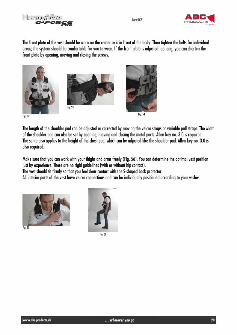
The front plate of the vest should be worn on the center axis in front of the body. Then tighten the belts for individual areas; the system should be comfortable for you to wear. If the front plate is adjusted too long, you can shorten the front plate by opening, moving and closing the screws.
The length of the shoulder pad can be adjusted or corrected by moving the velcro straps or variable pull straps. The width of the shoulder pad can also be set by opening, moving and closing the metal parts. Allen key no. 3.0 is required. The same also applies to the height of the chest pad, which can be adjusted like the shoulder pad. Allen key no. 3.0 is also required. Make sure that you can work with your thighs and arms freely (Fig. 56). You can determine the optimal vest position just by experience. There are no rigid guidelines (with or without hip contact). The vest should sit firmly so that you feel clear contact with the S-shaped back protector. All interior parts of the vest have velcro connections and can be individually positioned according to your wishes.
Fig. 52
Fig. 53
Fig. 54
Fig. 55
Fig. 56

APR07
www.abc-products.de … wherever you go 21
Setting the height adjustment for the spring arm / changing the left/right sled guide The element for mounting the spring arm can be mounted for left or right-bearing operators. To switch the position, open both smaller clamping levers (Fig. 57). Pull the mount out of the guide completely and turn it 180 degrees (Fig. 58 & 59). Re-attach the sled to the guide and adjust to the desired height by closing the clamping lever. Your preference for the post guide is crucial for the carrying position. Just try both variants.
Fig. 57
Fig. 58
Fig. 59
Fig. 60
Setting the adjustment angle The assembly unit also has a stepless angle adjustment option for the spring arm with -20 to +20 degrees of travel. This adjustment makes system balance possible depending on your natural body posture and shape or the task. Generally, an angle adjustment of up to 10-15 degrees to the rear is desired, i.e. raising the mounted spring arm. If the angle points too far forward, the system moves strongly away from the body and too much effort is expended to counteract the movement. If the angle points too far back, the system moves toward the body appropriately. The goal is to achieve a neutral angle position in which a natural, straight posture can be maintained and the system can be guided "near the body" without exertion. Freehand balance exercises show you the correction requirement.
Open the large clamping lever (Fig. 61). You can move the lever by pulling it and re-engaging it in position.
Fig. 61

APR07
www.abc-products.de … wherever you go 22
The screws for the angle adjustment are of varying lengths (Fig. 62). To adjust the angle toward the body, the long screw must be moved up. Adjust the angle as desired by tightening the top screw. You can then counter using the bottom screw. Then close the large clamping lever (opposite direction than as shown in Fig. 61). The angle mount should now fit again without any gap.
Fig. 62
Fig. 63
Fig. 64
Fig. 65
Mounting the spring arm Pull out the safety pin from the mount by pressing on the head of the pin. Guide the spring arm with the U-shaped mount over the angle mount. Line up the holes (Fig. 67) and secure the units by sliding in the safety pin until it engages (Fig. 68). Balance the spring arm in front of your body by moving the arm toward the front/back or left and right. Always return to a resting middle position. Mount or install the spring arm in the stand-by position in the tripod plate. If you still have the sled in the trim position, please relocate it.
Fig. 66
Fig. 67
Fig. 68
Fig. 69

APR07
www.abc-products.de … wherever you go 23
Mounting the sled to the spring arm Remove the safety screw from the tripod plate and park it in the intended mount. Move one step forward and to the knees under the gimbal and connect the gimbal pin to the mount. Tighten your stomach and back muscles and straighten up together with the sled safely and slowly. Guide the system out of the mount and put yourself into a relaxed upright position.
Fig. 70
Fig. 71
Fig. 72
Start with balancing exercises in which you find the ideal point at which the system easily moves and rests in front of your body. Once you have found this position, you can carefully attempt balancing exercises without your hands. Always feel your way to this ideal position with the sled locked. The goal is to get a feel for the interaction of your posture and weight with the collective behavior of the system. Guide the system with a "sensitive hand", i.e. without transferring force to the sled. It is enough to feel the grip or material. Only light pulses are required to bring the camera into the desired position.
Hand posture and guiding the sled
Hold the panning hand as close to the joint as possible. The further away the hand is from the gimbal, the stronger the effect pulse from the higher angle of deflection. The second hand (guide hand) rests on the connection piece to the gimbal. Press and pull the spring arm up and down to change the height of the rotational position.
Fig. 73
Fig. 74
Fig. 75
Fig. 72

APR07
www.abc-products.de … wherever you go 24
Adjusting the spring arm Each of the spring arm sections is equipped with two spring elements, whose pretension can be adjusted according to the weight of the camera. The Allen key 4.0 is required (Fig. 73). If the pretension is too high, the spring elements may not absorb the body's movements sufficiently. If the pretension is too low, movement spreads through the arm or much effort is required to hold the arm. The tension should be set so that the absorption range/spring travel is balanced up and down. Always correct the tension of the spring elements without load – and make sure that the tension on both springs is always adjusted synchronously for each segment.
Fig. 76
Fig. 77
Fig. 78
Fig. 79
Start with a pretension in which both elements are close to parallel under load. Then test and correct the pretension. Frequently, the front spring element easily faces upwards, the rear runs parallel. (Fig. 80)
Testing the trimming Quickly push and pull the system forward and backward, parallel with guide hand. If the system is correctly balanced – holds the position – there is no swinging motion (base too firm) and no rotation (side to side, left or right).
Fig. 80
Fig. 81
Fig. 82
Fig. 83
Also go around the system. Hold the sled with your guide hand only. The sled should stay in the middle.

APR07
www.abc-products.de … wherever you go 25
Fig. 84
Fig. 85
Fig. 86
Fig. 87
Low mode Open the clamping system of the gimbal and standing on its head lower the camera as desired. Then secure and close the clamping system, open the telescope and pull it up as far as you need to counterweight the camera. Now, mount the monitor turned 180 degrees at the desired position, hang the sled into the trim position and carry out any fine trimming using the weight extension on the post and side-to-side module. You must then flip the monitor picture 180 degrees (Fig. 80 or page 8). The picture must be flipped again later. Re-hang the sled in the stand-by position and mount again with the spring arm.
Fig. 88
Fig. 89
Fig. 90
Fig. 91

APR07
www.abc-products.de … wherever you go 26
Mounting the "Hoodman" anti-glare device Measure the top edge of the monitor housing (possibly mark the area to evenly affix the velcro strip). Then remove the protective film on the bottom of the velcro strip and attach the velcro evenly. Using the velcro fastener, mount the anti-glare device in the desired position.
Fig. 92
Fig. 93
Fig. 94

APR07
www.abc-products.de … wherever you go 27
Optional accessories
Mounting the bubble level, item no. 821497
Loosen the fixing screw for the bubble level and from the front, push onto the tubes of the battery sliding unit. Close the safety screw. The system must be re-balanced accordingly. Fig. 95
Mounting the digital voltage indicator, item no. 821481
Screw the voltage indicator onto the foot plate. A coin or screwdriver is required. Attach the connection cable to the power supply middle connection. Fig. 96
Sandbag for weighting the tripod, item no. 832100
A sandbag can also be attached to the tripod to improve its stability. Fig. 97
ABC-Products regularly offers workshops on operating the HandyMan G-Force. Simply request current workshop dates ([email protected]).

Under the roof of …
Movie Tech AG, located in Munich, is one of the leading manufactures of products and solutions for the film industry. The product line of Movie Tech AG includes the hole range of camera cranes, dollys, light systems, remote heads and related accessories. Movie Tech AG purpose is to build professio-nal film equipment to make the work for film teams on the set or in the studios easier. In order to fulfill customer's requests better, Movie Tech AG has branches in the U.S. and Italy.
Since 2006, MTS equipment has been added to the portfolio of MovieTech AG. MTS - Media Technical Systems - manufactures premium studio equip-ment, including droparms, pantographs, lighting hoists, and telescopes.
Movie Tech AG acquired the company ABC-Products in January 2000 with the objective to improve the development in the broadcast market. ABC-Products is today one of leading brands in the area of extremely light and high-grade broadcast equip-ment.
MovieTech AGMartin-Kollar-Str. 9 · 81829 München · GermanyTel. +49/89-4368913 · Fax +49/89-43689155e-mail: [email protected] · www.movietech.de www.movietech.de