WEJIT t 719 Techmanual
33
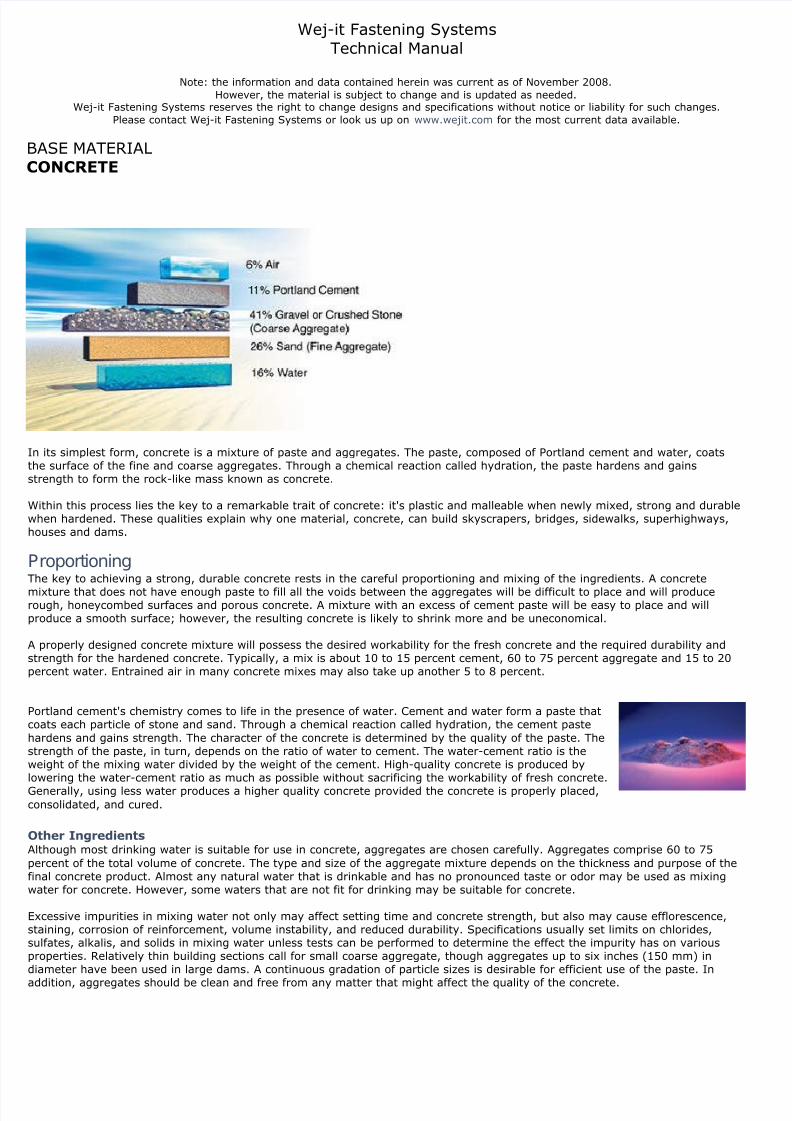
Wej-it Fastening Systems Technical Manual Note: the information and data contained herein was current as of November 2008. However, the material is subject to change and is updated as needed. Wej-it Fastening Systems reserves the right to change designs and specifications without notice or liability for such changes. Please contact Wej-it Fastening Systems or look us up on www.wejit.com for the most current data available. BASE MATERIAL CONCRETE In its simplest form, concrete is a mixture of paste and aggregates. The paste, composed of Portland cement and water, coats the surface of the fine and coarse aggregates. Through a chemical reaction called hydration, the paste hardens and gains strength to form the rock-like mass known as concrete. Within this process lies the key to a remarkable trait of concrete: it's plastic and malleable when newly mixed, strong and durable when hardened. These qualities explain why one material, concrete, can build skyscrapers, bridges, sidewalks, superhighways, houses and dams. P roport ioning The key to achieving a strong, durable concrete rests in the careful proportioning and mixing of the ingredients. A concrete mixture that does not have enough paste to fill all the voids between the aggregates will be difficult to place and will produce rough, honeycombed surfaces and porous concrete. A mixture with an excess of cement paste will be easy to place and will produce a smooth surface; however, the resulting concrete is likely to shrink more and be uneconomical. A properly designed concrete mixture will possess the desired workability for the fresh concrete and the required durability and strength for the hardened concrete. Typically, a mix is about 10 to 15 percent cement, 60 to 75 percent aggregate and 15 to 20 percent water. Entrained air in many concrete mixes may also take up another 5 to 8 percent. Portland cement's chemistry comes to life in the presence of water. Cement and water form a paste that coats each particle of stone and sand. Through a chemical reaction called hydration, the cement paste hardens and gains strength. The character of the concrete is determined by the quality of the paste. The strength of the paste, in turn, depends on the ratio of water to cement. The water-cement ratio is the weight of the mixing water divided by the weight of the cement. High-quality concrete is produced by lowering the water-cement ratio as much as possible without sacrificing the workability of fresh concrete. Generally, using less water produces a higher quality concrete provided the concrete is properly placed, consolidated, and cured. Other Ingredients Although most drinking water is suitable for use in concrete, aggregates are chosen carefully. Aggregates comprise 60 to 75 percent of the total volume of concrete. The type and size of the aggregate mixture depends on the thickness and purpose of the final concrete product. Almost any natural water that is drinkable and has no pronounced taste or odor may be used as mixing water for concrete. However, some waters that are not fit for drinking may be suitable for concrete. Excessive impurities in mixing water not only may affect setting time and concrete strength, but also may cause efflorescence, staining, corrosion of reinforcement, volume instability, and reduced durability. Specifications usually set limits on chlorides, sulfates, alkalis, and solids in mixing water unless tests can be performed to determine the effect the impurity has on various properties. Relatively thin building sections call for small coarse aggregate, though aggregates up to six inches (150 mm) in diameter have been used in large dams. A continuous gradation of particle sizes is desirable for efficient use of the paste. In addition, aggregates should be clean and free from any matter that might affect the quality of the concrete.
-
Upload
octavio-melchor-lucero -
Category
Documents
-
view
226 -
download
0
Transcript of WEJIT t 719 Techmanual
8/22/2019 WEJIT t 719 Techmanual
http://slidepdf.com/reader/full/wejit-t-719-techmanual 1/33
Wej-it Fastening SystemsTechnical Manual
Note: the information and data contained herein was current as of November 2008.However, the material is subject to change and is updated as needed.
Wej-it Fastening Systems reserves the right to change designs and specifications without notice or liability for such changes.Please contact Wej-it Fastening Systems or look us up on www.wejit.com for the most current data available.
BASE MATERIALCONCRETE
n its simplest form, concrete is a mixture of paste and aggregates. The paste, composed of Portland cement and water, coatshe surface of the fine and coarse aggregates. Through a chemical reaction called hydration, the paste hardens and gainstrength to form the rock-like mass known as concrete.
Within this process lies the key to a remarkable trait of concrete: it's plastic and malleable when newly mixed, strong and durablewhen hardened. These qualities explain why one material, concrete, can build skyscrapers, bridges, sidewalks, superhighways,houses and dams.
Proportioning
The key to achieving a strong, durable concrete rests in the careful proportioning and mixing of the ingredients. A concrete
mixture that does not have enough paste to fill all the voids between the aggregates will be difficult to place and will produceough, honeycombed surfaces and porous concrete. A mixture with an excess of cement paste will be easy to place and will
produce a smooth surface; however, the resulting concrete is likely to shrink more and be uneconomical.
A properly designed concrete mixture will possess the desired workability for the fresh concrete and the required durability andtrength for the hardened concrete. Typically, a mix is about 10 to 15 percent cement, 60 to 75 percent aggregate and 15 to 20
percent water. Entrained air in many concrete mixes may also take up another 5 to 8 percent.
Portland cement's chemistry comes to life in the presence of water. Cement and water form a paste thatoats each particle of stone and sand. Through a chemical reaction called hydration, the cement paste
hardens and gains strength. The character of the concrete is determined by the quality of the paste. Thetrength of the paste, in turn, depends on the ratio of water to cement. The water-cement ratio is the
weight of the mixing water divided by the weight of the cement. High-quality concrete is produced byowering the water-cement ratio as much as possible without sacrificing the workability of fresh concrete.
Generally, using less water produces a higher quality concrete provided the concrete is properly placed,onsolidated, and cured.
Other Ingredients Although most drinking water is suitable for use in concrete, aggregates are chosen carefully. Aggregates comprise 60 to 75percent of the total volume of concrete. The type and size of the aggregate mixture depends on the thickness and purpose of theinal concrete product. Almost any natural water that is drinkable and has no pronounced taste or odor may be used as mixing
water for concrete. However, some waters that are not fit for drinking may be suitable for concrete.
Excessive impurities in mixing water not only may affect setting time and concrete strength, but also may cause efflorescence,taining, corrosion of reinforcement, volume instability, and reduced durability. Specifications usually set limits on chlorides,ulfates, alkalis, and solids in mixing water unless tests can be performed to determine the effect the impurity has on various
properties. Relatively thin building sections call for small coarse aggregate, though aggregates up to six inches (150 mm) indiameter have been used in large dams. A continuous gradation of particle sizes is desirable for efficient use of the paste. In
ddition, aggregates should be clean and free from any matter that might affect the quality of the concrete.
8/22/2019 WEJIT t 719 Techmanual
http://slidepdf.com/reader/full/wejit-t-719-techmanual 2/33
Hydration Begins Soon after the aggregates, water, and the cement are combined, the mixture starts to harden. All portland cements are hydraulicements that set and harden through a chemical reaction with water. During this reaction, called hydration, a node forms on theurface of each cement particle. The node grows and expands until it links up with nodes from other cement particles or adhereso adjacent aggregates.
The building up process results in progressive stiffening, hardening, and strength development. Once the concrete is thoroughlymixed and workable it should be placed in forms before the mixture becomes too stiff.
During placement, the concrete is consolidated to compact it within the forms and to eliminate potential flaws, such as
honeycombs and air pockets. For slabs, concrete is left to stand until the surface moisture film disappears. After the filmdisappears from the surface, a wood or metal hand float is used to smooth off the concrete. Floating produces a relatively even,but slightly rough, texture that has good slip resistance and is frequently used as a final finish for exterior slabs. If a smooth,hard, dense surface is required, floating is followed by steel troweling.
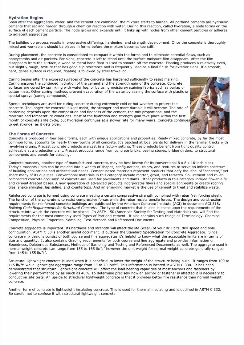
Curing begins after the exposed surfaces of the concrete has hardened sufficiently to resist marring.Curing ensures the continued hydration of the cement and the strength gain of the concrete. Concreteurfaces are cured by sprinkling with water fog, or by using moisture-retaining fabrics such as burlap orotton mats. Other curing methods prevent evaporation of the water by sealing the surface with plastic orpecial sprays (curing compounds).
Special techniques are used for curing concrete during extremely cold or hot weather to protect theoncrete. The longer the concrete is kept moist, the stronger and more durable it will become. The rate of
hardening depends upon the composition and fineness of the cement, the mix proportions, and themoisture and temperature conditions. Most of the hydration and strength gain take place within the first
month of concrete's life cycle, but hydration continues at a slower rate for many years. Concrete continueso get stronger as it gets older.
The Forms of Concrete
Concrete is produced in four basic forms, each with unique applications and properties. Ready mixed concrete, by far the mostommon form, accounts for nearly three-fourths of all concrete. It's batched at local plants for delivery in the familiar trucks withevolving drums. Precast concrete products are cast in a factory setting. These products benefit from tight quality controlchievable at a production plant. Precast products range from concrete bricks, paving stones, bridge girders, to structuralomponents and panels for cladding.
Concrete masonry, another type of manufactured concrete, may be best known for its conventional 8 x 8 x 16-inch block.Today's masonry units can be molded into a wealth of shapes, configurations, colors, and textures to serve an infinite spectrumof building applications and architectural needs. Cement-based materials represent products that defy the label of "concrete," yethare many of its qualities. Conventional materials in this category include mortar, grout, and terrazzo. Soil-cement and roller-ompacted concrete-"cousins" of concrete-are used for pavements and dams. Other products in this category include flowable fillnd cement-treated bases. A new generation of advanced products incorporates fibers and special aggregate to create roofingiles, shake shingles, lap siding, and countertops. And an emerging market is the use of cement to treat and stabilize waste.
Reinforced concrete is formed using concrete meeting a certain compressive strength combined with rebar (reinforcing steel).The function of the concrete is to resist compressive forces while the rebar resists tensile forces. The design and constructionequirements for reinforced concrete buildings are published by the American Concrete Institute (ACI) in document ACI 318,
Building Code Requirements for Structural Concrete. The type of concrete that is used is based upon the requirements of thetructure into which the concrete will be placed. In ASTM 150 (American Society for Testing and Materials) you will find theequirements for the most commonly used Types of Portland cement. It also contains such things as Terminology, Chemical
Composition, Physical Properties, Sampling, Test Methods and Referenced Documents.
Concrete aggregate is important. Its hardness and strength will affect the life (wear) of your drill bits, drill speed and holeonfiguration. ASTM C 33 is another useful document. It outlines the Standard Specification for Concrete Aggregate. Sinceoncrete mix designs consist of both course and fine aggregates it’s helpful to know what the acceptable limits are in terms of
ize and quantity. It also contains Grading requirements for both course and fine aggregate and provides information onSoundness, Deleterious Substances, Methods of Sampling and Testing and Referenced Documents as well. The aggregate used innormal weight concrete can range from 135 to 165 lb/ft3 however the unit weight for normal weight concrete generally rangesrom 145 to 155 lb/ft3.
Structural lightweight concrete is used when it is beneficial to lower the weight of the structure being built. It ranges from 100 to115 lb/ft3 while lightweight aggregate range from 55 to 70 lb/ft3. This information is located in ASTM C 330. It has beendemonstrated that structural lightweight concrete will affect the load bearing capacities of most anchors and fasteners byowering their performance by as much as 40%. To determine precisely how an anchor or fastener is affected it is necessary toonduct on site tests. An upside to structural lightweight concrete is that it provides better fire resistance than normal weightoncrete.
Another form of concrete is lightweight insulating concrete. This is used for thermal insulating and is outlined in ASTM C 332.Be careful not to confuse it with structural lightweight concrete.

8/22/2019 WEJIT t 719 Techmanual
http://slidepdf.com/reader/full/wejit-t-719-techmanual 3/33
While the type of admixtures, cement and aggregate have an effect on the compressive strength of the concrete, the water toement ratio is the primary factor affecting the strength. As the water to cement ratio decreases, the compressive strength of theement increases. In order to determine the compressive strength of concrete, test specimens are formed in cylinders accordingo ASTM C 31 and crushed at specific time intervals according to ASTM C 39. The resulting strength is documented to the
nearest 10 psi increment.
Any load capacity listed in this manual is for concrete that has cured a minimum of 28 days unless otherwise noted. Job site testsre recommended for installations in concrete where the material strength or condition is unknown. The load capacities listed inhis manual were conducted in un-reinforced concrete test members to provide data which is useable regardless of the possible
benefit of reinforcement.
Concrete Reinforcing Bar (Rebar)
n the United States, the size designations of these mild steel bars used to reinforce concrete are set by ASTM International. 1 Distributors usually stock rebar in 20- and 60-foot lengths. Most bars are “deformed,” that is, a pattern is rolled onto them whichelps the concrete get a grip on the bar. The exact patterns are not specified, but the spacing, number and height of the bumps a
Between 1947 and 1968, a separate standard (ASTM A 305) covered the deformations. Since 1968 the deformation requirementsave been incorporated in the basic standard. Plain bars are also made, but are used only in special situations in which the bars axpected to slide (for example, crossing expansion joints in highway pavement).
Three grades are defined, with metric equivalents:
inch-poundgrade
metricgrade
Minimum Yield Strength
in poundsper square inch
inmegapascals
Grade 40 Grade 280 40,000 280
Grade 60 Grade 420 60,000 420
Grade 75 Grade 520 75,000 520
According to the standard (sec. 20.3.5), "it shall be permissible to substitute a metric size bar of Grade 280 for theorresponding inch-pound size bar of Grade 40, a metric size bar of Grade 420 for the corresponding inch-pound size bar of Grade0, and a metric size bar of Grade 520 for the corresponding inch-pound size bar of Grade 75." Nothing is said regarding substitut
nch-pound size bars when the specification is metric.
The size designations are the number of eighths of an inch in the diameter of a plain round bar having the same weight peoot as the deformed bar. So, for example, a number 5 bar would have the same mass per foot as a plain bar 5/8 inch in diametehe metric size is the same dimension expressed to the nearest millimeter.
8/22/2019 WEJIT t 719 Techmanual
http://slidepdf.com/reader/full/wejit-t-719-techmanual 4/33
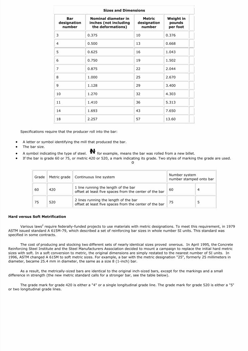
Sizes and Dimensions
Bardesignation
number
Nominal diameter ininches (not including
the deformations)
Metricdesignation
number
Weight inpoundsper foot
3 0.375 10 0.376
4 0.500 13 0.668
5 0.625 16 1.043
6 0.750 19 1.502
7 0.875 22 2.044
8 1.000 25 2.670
9 1.128 29 3.400
10 1.270 32 4.303
11 1.410 36 5.313
14 1.693 43 7.650
18 2.257 57 13.60
Specifications require that the producer roll into the bar:
A letter or symbol identifying the mill that produced the bar.
The bar size.
A symbol indicating the type of steel. for example, means the bar was rolled from a new billet.
If the bar is grade 60 or 75, or metric 420 or 520, a mark indicating its grade. Two styles of marking the grade are used.o
Grade Metric grade Continuous line systemNumber systemnumber stamped onto bar
60 4201 line running the length of the baroffset at least five spaces from the center of the bar
60 4
75 5202 lines running the length of the baroffset at least five spaces from the center of the bar
75 5
Hard versus Soft Metrification
Various laws2 require federally-funded projects to use materials with metric designations. To meet this requirement, in 197ASTM issued standard A 615M-79, which described a set of reinforcing bar sizes in whole number SI units. This standard waspecified in some contracts.
The cost of producing and stocking two different sets of nearly identical sizes proved onerous. In April 1995, the ConcreteReinforcing Steel Institute and the Steel Manufacturers Association decided to mount a campaign to replace the initial hard metricizes with soft. In a soft conversion to metric, the original dimensions are simply restated to the nearest number of SI units. In996, ASTM changed A 615M to soft metric sizes. For example, a bar with the metric designation "25", formerly 25 millimeters iniameter, became 25.4 mm in diameter, the same as a size 8 (1-inch) bar.
As a result, the metrically-sized bars are identical to the original inch-sized bars, except for the markings and a smallifference in strength (the new metric standard calls for a stronger bar, see the table below).
The grade mark for grade 420 is either a "4" or a single longitudinal grade line. The grade mark for grade 520 is either a "5r two longitudinal grade lines.

8/22/2019 WEJIT t 719 Techmanual
http://slidepdf.com/reader/full/wejit-t-719-techmanual 5/33
Type of steel mark
Mark MeaningApplicable ASTM Standard by Grade
40 & 50 60 75 300 & 350 420 520
S billet A615 A615 A615 A615M A615M A615M
I rail A616 A616 — A996M A996M —
IRRail Meeting SupplementaryRequirements S1
A616 A616 — — — —
A axle A617 A617 — A996M A996M —
WLow-alloy
— A706 — — A706M —
Grades and Minimum Steel Strength
old USgrade
minimumyield strength
Correspondingcurrent
soft metric
grade
minimum yield strength
original
hard metricspecs
1996
revisions proposal
40 40,000 psi 300300 MPa(43,400 psi)
— —
60 60,000 psi 420400 MPa(58,000 psi)
420 MPa(60,900 psi)
415 MPa(60,100 psi)
75 75,000 psi 520500 MPa(72,500 psi)
520 MPa(75,400 psi)
—
. ASTM International issues a series of specifications for rebar:
A615/A615M-05a: Standard Specification for Deformed and Plain Billet-Steel Bars for Concrete Reinforcement. (covers grades 40
0/soft metric grades 420 and 520)
A616: Standard Specification for Rail-Steel Deformed Bars for Concrete Reinforcement. (covers grades 50 and 60).
A617: Standard Specification for Axle-Steel Deformed Bars for Concrete Reinforcement. (covers grades 40 and 60)
A706/A706M-96b: Standard Specification for Low-Alloy-Steel Deformed and Plain Bars for Concrete Reinforcement. (grade 60 only
. Metric Conversion Act of 1975; Omnibus Trade and Competitiveness Act of 1988 (Public Law 100-418, section 5164); Executive
Order 12770, "Metric Usage in Federal Government Programs."

8/22/2019 WEJIT t 719 Techmanual
http://slidepdf.com/reader/full/wejit-t-719-techmanual 6/33
Rebar Rebar Grade 40 Rebar Grade 60 Rebar Grade 75 Rebar
Size Area Allowable Yield Ultimate Allowable Yield Ultimate Allowable Yield Ultimate
d Tension Strength Strength Tension Strength Strength Tension Strength Strength
Ø lbs. lbs. lbs. lbs. lbs. lbs. lbs. lbs. lbs.
No. 3 0.110 2209 4418 7731 2651 6627 9940 NO DATA 8284 11045
No. 4 0.196 3927 7854 13745 4712 11781 17672 NO DATA 14726 19635
No. 5 0.307 6136 12272 21476 7363 18408 27612 NO DATA 23010 30680
No. 6 0.442 8836 17672 30925 10603 26507 39761 NO DATA 33134 44179
No. 7 0.601 12026 24053 42093 14432 36079 54119 NO DATA 45099 60132
No. 8 0.785 15708 31416 54978 18850 47124 70686 NO DATA 58905 78540
No. 9 0.999 19987 39973 69953 23984 59960 89940 NO DATA 74950 99933
No. 10 1.267 25335 50671 88674 30403 76006 114009 NO DATA 95008 126677
No. 11 1.561 31229 62458 109302 37475 93687 140531 NO DATA 117109 156145
No. 14 2.251 45023 90046 157581 54028 135069 202604 NO DATA 168836 225115
No. 18 4.001 80017 160035 280061 96021 240052 360078 NO DATA 300065 400087
he strengths listed in the table above are calculated based on the stresses in the following table. The allowable tension is basedhe building code ACI 318. Section 9.4 permits designs based on a yield strength of up to a maximum of 80,000 psi. Currently ths no ASTM specification for Grade 80 reinforcement. However, deformed reinforcing bars No. 6 through No. 18 with a yield strengf 75,000 psi (Grade75) are included in the ASTM A 615 specification. “Section 3.5.3.2 requires that the yield strength of greaterhan 60,000 psi be taken as the stress corresponding to a strain of 0.35 percent. The 0.35 percent limit is to ensure that the elastlastic stress-strain curve assumed in 10.2.4 will not result in unconservative values of member strength. Therefore the designerhould be aware that if ASTM A 615, Grade 75 bars are specified, the project specifications need to include a requirement that theield strength of the bars shall be determined in accordance with Section 9.2.2 of the ASTM A 615 specification.”
Grade 40 Rebar Grade 60 Rebar Grade 75 Rebar
Allowable Yield Ultimate Allowable Yield Ultimate Allowable Yield Ultimate
Tension Strength Strength Tension Strength Strength Tension Strength Strength
lbs. lbs. lbs. lbs. lbs. lbs. lbs. lbs. lbs.
20000 40000 70000 24000 60000 90000 N/A 75000 100000
ACC) Autoclaved Concrete is an aerated lightweight material that has been used in other parts of the world but is relatively new the market in United States. It’s made of pulverized sand, water, cement and lime however there is no large aggregate in the
mixture. The ingredients are all mixed together to make a paste which is then deposited into molds for forming. The chemicaleaction created creates and traps air bubbles within the solid mix. The batch is allowed to set and then before final hardeningccurs is cut into portions of the desired size. The portions are them hardened & cured in an autoclave utilizing steam underressure. ACC is available as you might imagine in a wide variety and combinations of block height, length, thickness’ andompressive strengths. ACC is used successfully in many applications such as mines, firewalls, shaft wall construction highway so
walls, exterior wall panels, reinforced panels, load bearing vertical panels, floor and roof panels.ASTM C 1386 contains specifications for ACC unreinforced block elements and ASTM C 1452 contains those for reinforced panellements.
8/22/2019 WEJIT t 719 Techmanual
http://slidepdf.com/reader/full/wejit-t-719-techmanual 7/33
MASONRY MATERIALS
Generally speaking, concrete is capable of sustaining higher loads than brick or block. As the embedment depth of an anchor orastener increases, the tension load will increase up to a point at which either the capacity of the expansion mechanism or bond iseached or the concrete fails. The strength of masonry walls is usually less than that of concrete and the consistency of this matean vary from region to region. To form a wall individual masonry units are bonded together with a cement mortar. The VERTICA
ROW is called the COURSE and the HORIZONTAL ROW is called a WYTHE.he strength of the mortar is often the critical factor in product performance. Anchors or fasteners must be installed in the horizo
mortar joint or in some cases directly into the masonry unit.n testing products should be installed and loaded to simulate the actual anchor or fastener placement. These tests are usually dn an unrestrained mode. That is to say that the reaction bridge is spanning the installation without influencing anchor performanc
Hollow base material require special care and consideration as the anchor or fastener must be properly sized to coincide with the hickness or selected to properly expand in the void. This material is very susceptible to reverse spalling thus reducing even furthhe normally thin wall thickness’. Manufacturers of hollow block often will specify the maximum load that can be applied to the
material and this must always be kept in mind. Since the strength of masonry materials varies widely, on site testing areecommended to determine actual load capacities for any critical application that you may have.
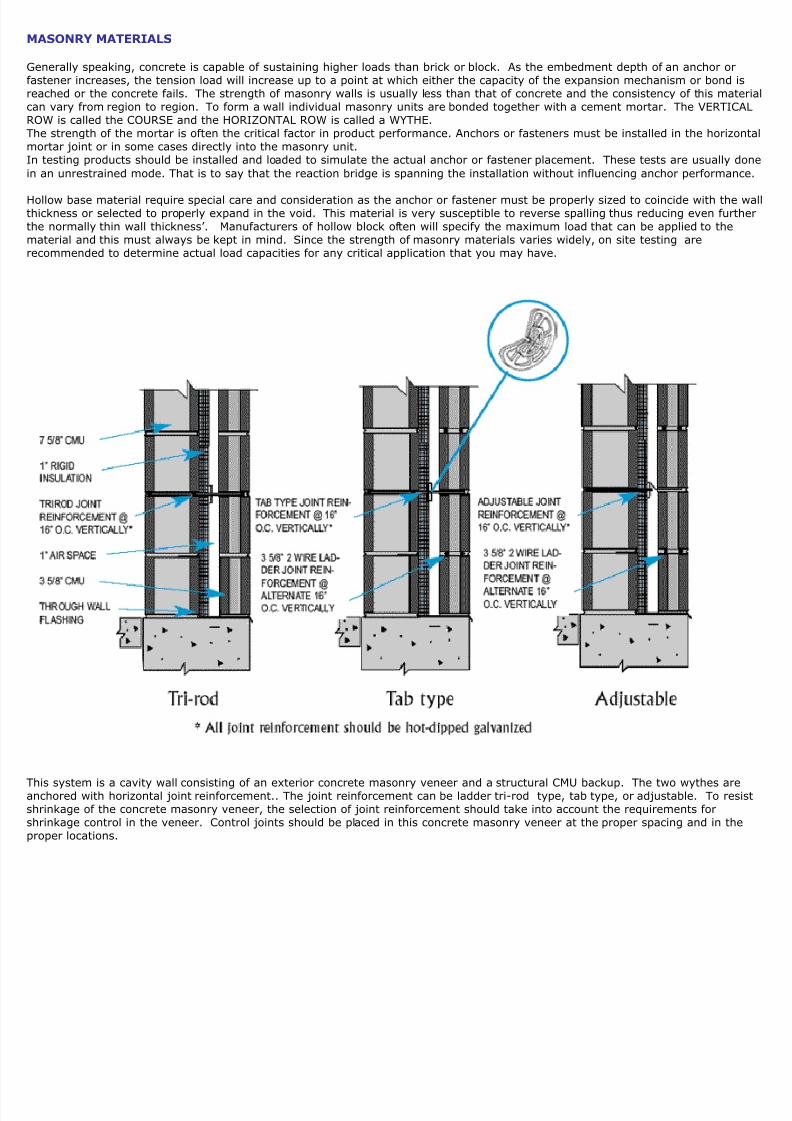
his system is a cavity wall consisting of an exterior concrete masonry veneer and a structural CMU backup. The two wythes arenchored with horizontal joint reinforcement.. The joint reinforcement can be ladder tri-rod type, tab type, or adjustable. To reshrinkage of the concrete masonry veneer, the selection of joint reinforcement should take into account the requirements forhrinkage control in the veneer. Control joints should be placed in this concrete masonry veneer at the proper spacing and in theroper locations.

8/22/2019 WEJIT t 719 Techmanual
http://slidepdf.com/reader/full/wejit-t-719-techmanual 8/33
Concrete Block Walls
MU stands for concrete masonry unit, which is the 8x8x16-inch concrete block that makes up CMU walls. CMUs have been improvingaterials and mixtures since 1882, but their general size and purpose remains the same. Popularly used as a standard building material, Cmply precast concrete blocks, meaning that they have been molded to a specific shape and size to build a block or rock retaining wall.ade from cement, aggregates and water, CMUs are formed in molding equipment and allowed to cure. Curing implies that the concrete Cot dry as it hardens but rather retains moisture as it strengthens. Retaining water is part of what gives the concrete block its integrity. addition to the ingredients listed above, CMU mixtures may include a host of optional admixtures created to enhance or change the fina
MU block’s characteristics. By adding such ingredients, the manufacturer may be able to strengthen, air-entrain, color, accelerate curing tard or plasticize the CMU. For example, air bubbles disperse in concrete (know as air-entraining) to protect against freezing and thawing
onditions. Plasticizers help make concrete more workable while forming it.
s they are manufactured, CMUs are generally formed in a concrete forming machine that takes moist concrete and quickly pours it into thesired block dimensions. Placed in chambers that have extremely high temperatures, the CMU blocks undergo accelerated curing. Finally,ored for a specific period of time to promote further curing prior to shipment. These CMU blocks are designed to ultimately be the core fond buildings that need to be fabricated economically, efficiently and for fire-resistance.s the finalized CMU blocks are identical, they provide a good material to build a solid wall. The CMU blocks are stacked in layers with moretween each block. This process allows for flexible and versatile concrete masonry construction.MUs are formed for many different purposes and include various masonry unit types including split face concrete block, slotted and glazedplit face CMUs are formed as one unit and then split revealing the rough aggregate texture. Slotted CMUs offer high sound absorption in here a sound barrier wall may be need. Glazed CMUs are primarily used when an aesthetically pleasing finish is desired. Both hollow andpes which can be classified as load bearing or non-load bearing are used. CMU blocks are usually considered to be a load bearing masonr
nd suitable for anchoring and fastening. However on site tests are always recommended for critical applications. ASTM C 90 describes hoolid load bearing concrete masonry unit made from Portland cement, water and mineral aggregates in normal, medium and lightweightassifications. (Standard Specification for Loadbearing Concrete Masonry Units)
CMU & Blended CMU - 8x8x16 Standard
5/8” = Block Width5/8” = Block Height5 5/8” = Block Facend the Web cross sections the Hollow Cell

8/22/2019 WEJIT t 719 Techmanual
http://slidepdf.com/reader/full/wejit-t-719-techmanual 9/33
CMU Concrete Block Walls cont.
he way to differentiate between hollow and solid block is based on their cross sectional area. Technically, solid block is defined aaving a cross sectional bearing area which is not less than 75% of the gross area of the block when measured in the same planeypical dimensions of the Block face and web based upon ASTM C 90 are as follows:
Nominal CMU Face WebWidth Thickness Thickness
Inches Inches Inches
3 ¾ ¾
4 ¾ ¾
6 1 1
8 1 ¼ 1 ¼
1 3/8 1 1/81o 1 ¼ 1 1/8
1 1/2 1 1/8
12 1 ¼ 1 1/8
Mortar Type CompressiveStrength
M 2500psiS 1800psi
Center – Lime N 750psiMasonry/Cement O 350psi
Although improving, the consistency of grout filled block walls is variable and on site testing is still the preferred way to determine
more exact performance. Some times when lateral support is needed steel reinforcing rods are installed through the block hollownd then grouted in place. This allows the unit to act in harmony to resist lateral loads.

8/22/2019 WEJIT t 719 Techmanual
http://slidepdf.com/reader/full/wejit-t-719-techmanual 10/33
Brick
n 210 BC, the Great Wall of China was constructed of brick — nearly four million of them. And the Romans used kiln-burned brickonjunction with an efficient mortar of lime and volcanic ash to construct buildings that were both beautiful and enduring. As the
Roman Empire declined, however, the art of brick making disappeared from most of Europe, only to be revived during the late MidAges by Italian and Byzantine artisans who had kept the technology alive.
Because it is made from the elements, brick stands up to them, like no other building material can. It resists pests and withstandre. It buffers sound. It warms us in the winter, and in the summer, helps to keep us cool. For thousands of years, brick has been
material of choice for strength and beauty. When brick is utilized as a building façade it’s imperative to tie it to the backing wall anuilding structure. One should use a non-corrosive anchor made from Stainless Steel when tying these walls together. ASTM C 6tandard Specification for Building Brick (Solid Masonry Units Made From Clay and Shale) outlines the various grades of brick usetructural and non-structural masonry applications. Grades such as, Grade SW (Severe Weathering), Grade MW (Moderate
Weathering) and Grade NW (Negligible Weathering). Compressive strength ranges as well as permissible variations in dimensionsweathering index and many other helpful pieces of information are located in this ASTM Standard along with other referenceocuments such as:
ASTM C 43 – Terminology of Structural Clay ProductsASTM C 67 – Test Methods for Sampling and Testing Brick and Structural TileASTM C 216 – Specification for Facing Brick (Solid Masonry Units from Clay or Shale)
Stone
Dimension stone can be defined as natural rock material quarried for the purpose of obtaining blocks or slabs thatmeet specifications as to size (width, length, and thickness) and shape. Color, grain texture and pattern, andurface finish of the stone are normal requirements. Durability (essentially based on mineral composition andardness and past performance), strength, and the ability of the stone to take a polish are other importantelection criteria.
Although a variety of igneous, metamorphic, and sedimentary rocks are used as dimension stone, the principalock types are granite, limestone, marble, sandstone, and slate. Other varieties of dimension stone that areormally considered to be special minor types include alabaster (massive gypsum), soapstone (massive talc), andarious products fashioned from natural stone. Granite is an example of an igneous stone while marble is
metamorphic. Both of these stones tend to be harder than limestone and sandstone which are sedimentarymaterials.
Natural stone is available in a variety of colors, types and textures for use in many building applications as well. But strength and
uality can vary significantly from quarry to quarry and location to location. So when checking anchor capacities be certain that now what material the anchors were tested in. Job site testing is recommended because of the wide variation in the strength oftone.
ASTM C119 – Standard Terminology Relating to Dimensional Stone describes dimensional stone for use in building construction.ASTM C 503 – MarbleASTM C 615 – GraniteASTM C 616 – Quartz andASTM C 568 – Limestone

8/22/2019 WEJIT t 719 Techmanual
http://slidepdf.com/reader/full/wejit-t-719-techmanual 11/33
Structural Clay Tile
Hollow masonry units, made of burned clay or shale are called variously; structural tiles, hollow tiles, structural clay tiles,tructural clay hollow tiles and structural clay hollow building tiles, but they are most commonly just called building tile.n building tile manufacture, plastic clay is pugged through a die, and the shape that emerges is cut off into units. The units are turned much as bricks are burned. The apertures in a building tile, which correspond to the cores in a brick or a concrete block, aalled CELLS. The solid sides of a tile are called the SHELL and the perforated material enclosed by the shell is called the WEB.
A tile that is laid on one of its shell faces is called a SIDE-CONSTRUCTION tile; one that is laid on one of its web faces is called anND-CONSTRUCTION tile.he typical thickness of the outer shell is ¾” with a ½” thick inner web. Structural Clay tile is not an easy material to fasten in safor heavier loads an adhesive anchor utilizing screens as carriers works best For lighter applications use an anchor which has thebility to open up behind the face and in the web cavity. Grading of Structural Clay tile can be found in ASTM C 212 and ASTM C 3
Grade LBX is suitable for exposure to weather and Grade LB is suitable for general use` in masonry where not exposed to frost acr for use in exposed masonry where protected with a facing of 3”.
Steel Decking
teel deck is used as both a roof deck and for floors. (Composite and non composite) There are many configurations of steel deckut most are cold formed from a single steel sheet. Steel deck is known by it’s deck type, depth and gage thickness. Steel deck cae provided uncoated, painted or zinc coated in accordance with ASTM A 525 – Specification for General Requirements for Steelheet.he yield strength of steel deck varies based on its grade. Steel deck is generally specified by it’s thickness in decimal inches rathhan it’s gage.
Steel Gage Thickness9 0.149510 0.134511 0.119612 0.104613 0.0897
14 0.074715 0.067316 0.059817 0.0538
18 0.047419 0.041820 0.0359
21 0.032922 0.0299
23 0.026924 0.023925 0.020926 0.017927 0.0149
lood decking for construction (composite) with concrete fill typically has rib depths of 1 ½”, 2” and 3”. Other depths up to 7 are available. Non-composite steel form deck is used as a permanent form for concrete slabs with rib depths that are typically ½” to or steel roof deck, the ribs are classified as narrow, intermediate or wide. They have a 1 1/2” minimum depth that is spaced at n center. There is also a Deep Rib deck that has a minimum depth of 3” with an 8” on center spacing. There are a variety of othess common roof decks available as well such as acoustical sound absorbing, long span decks, cellular and sound absorbing floorecks.
8/22/2019 WEJIT t 719 Techmanual
http://slidepdf.com/reader/full/wejit-t-719-techmanual 12/33
Gypsum Concrete Decking
A gypsum concrete roof deck consists of gypsum concrete that is mixed with either wood fibers or mineral aggregate. The density ried gypsum concrete varies from 30 to 55 pounds per cubic foot, depending upon the design mix and the type of aggregate. The
mixture forms a slurry that is poured over vapor permeable form boards that are supported by sub purlins and the building'sssociated framing system. The sub purlins are installed to support the form boards and to anchor the deck to the building's framystem. The gypsum concrete mixture shall be reinforced with steel bars or a wire mesh. The reinforcing metal may be either a
welded or woven galvanized wire.
he form boards remains in place after installation of the gypsum concrete, and can provide a finished interior surface. The vaporermeable form boards allow additional drying of the gypsum concrete to the interior of the building. Various types of form boards
re available to provide enhanced interior light reflection, added fire resistance, insulation, and acoustic control.
Gypsum Concrete Design Requirements: Design requirements from the gypsum concrete manufacturer and from the NationaRoof Deck Contractors Association should be obtained for information pertinent to the specifications for gypsum roof decks.
Three general requirements for gypsum decks:
1. The gypsum fill shall be reinforced with steel or a wire mesh, located atthe correct depth within the deck
2. Gypsum decks shall have a minimum compressive strength of 500pounds per square inch.
3. Gypsum decks shall have a minimum thickness of 2", not including theform board, and shall extend a minimum of .25" above the top of bulbtees or other structural supports.
Structural Supports: Gypsum concrete roof decks and their underlying form boards are to be supported by sub purlins that spahe distance between the main purlins or joists. The three common types of steel sub purlins for this installation are:
1. Bulb tees
2. Truss tees
3. Cold rolled steel tees
Venting & Drying: Adequate interior ventilation must be provided below the deck to dry excess moisture from the poured gypsuhe form board, and other moisture generating construction processes. When possible, the building shall be edge vented to assistissipating residual moisture.
ASTM C 317 – Stand Specification for Gypsum Concrete describes mill mixed gypsum concrete for use in poured in place roof deckraditionally, setting times are assumed to be between 20 minutes to a maximum of 90 minutes and as stated earlier 500 psi for
Class A and 1000 psi for Class B gypsum. Density, strength and physical conditioning of gypsum varies widely so for exact anchoerformance on site testing is always recommended.
Gypsum Wallboard
Ordinary gypsum wallboard is sold in 4’ widths that range from ¼”, 3/8”, ½”, and 5/8” thick and come in lengths that range from eet to 16 feet long. Gypsum wallboard is also available in ¾”, 1” and 2” thickness’ which are normally used as floor underlaymentcoustical reasons and for other sound deadening applications.
Gypsum wallboard, often referred to as drywall or plaster board, is a building panel consisting mainly of a noncombustible gypsumore material sandwiched between two durable paper faces.hese panels or sheets are used most often as a simple, cost-efficient interior wall construction material for both residential andommercial projects. Enhanced with a variety of core additives and/or backer variations, gypsum wallboard can provide a range o
erformance characteristics for specialty applications including:
moisture-resistant tile backingheat-resistant fire protectionsag-resistant ceiling panelsdamage-resistant wall protectionexterior sheathing and soffit installationcurved wall surface construction
n addition, properly installed gypsum wallboard adds strength and sound resistance to interior walls improving the living and wornvironment of any facility constructed with this versatile material. Originally made entirely from mined gypsum rock, 60% of cur
wallboard production capacity is manufactured with a synthetic gypsum core to provide a product that not only performs well but lso environmentally responsible.ee ASTM C 36 – Standard Specification for Gypsum Wallboard for specifics.

8/22/2019 WEJIT t 719 Techmanual
http://slidepdf.com/reader/full/wejit-t-719-techmanual 13/33
Structural Wood Panels
tructural wood panels are manufactured in several grades from a wide variety of wood base materials. Plywood and OSB – Orietrand Board are the most common and have many uses.
Uses for wood panels include wall and roof sheathing, floor underlayments, ceilings, and interior walls. Wood is a renewable produ
nd requires less energy than most materials to process into finished products. The invention of plywood helped reduce the amou
f solid lumber and labor required for wood frame construction. Subsequent development and popularity of oriented strand board
OSB), manufactured from small fast growing trees such as aspen and poplar, has further reduced wood use per square foot of
tandard construction. Plywood consists of multiple veneers bound with a resin, usually urea formaldehyde (UF) for interior grade
nd the more water resistant phenol formaldehyde (PF) for exterior grade products.
Plywood has been made for thousands of years; the earliest known occurrence of plywood was in ancient Egypt around 3500 BCwhen wooden articles were made from sawn veneers glued together crosswise. This was originally done due to a shortage of finewood. Thin sheets of high quality wood were glued over a substrate of lower quality wood for cosmetic effect, with incidentaltructural benefits. This manner of inventing plywood has occurred repeatedly throughout history. Many of the great English furni
makers used veneer as a raw material.
Modern plywood in which the veneer are cut on a rotary lathe from softwood logs is of relatively recent origin, invented by ImmanNobel. The first such lathes were set up in the United States in the mid 19th century. Plywood has been one of the most ubiquitouuilding products for decades.
lywood grades are determined by the veneer quality on the face and back of each panel. The first letter designates quality of faceneer (best side), while the second letter denotes the surface quality of the back of the panel. The letter "X" simply indicates theanel was manufactured with exterior type adhesive.
A" Highest grade quality available. Can be defect free or contain small knots, providing they are replaced with wooden plugs orepaired with synthetic patch. May contain occasional surface splits that are repaired with synthetic filler. Surface is always sandend provides for smooth paintable face quality.
B" Second highest quality veneer grade. Normally a by-product of downgraded "A" quality veneer. Solid surface, but may containmall diameter knots and narrow surface splits. Normally repaired with wooden plugs or synthetic filler. Surface normally sandedmooth.
C" Considered to be a lower end face quality, but a reasonable choice for general construction purposes. May contain tight knots o 1-1/2" diameter, some open knot holes, some face splits, and discoloration. Some manufactures may repair the defects withynthetic filler. Panels typically not sanded.
D" Considered to be the lowest quality veneer and often used for the back surface for construction grade panels. Allows for sevenots, large and small, as well as open knots up to 2-1/2" diameter. Open knots, splits, and discoloration are acceptable. "D" gradeneers are never repaired or sanded. Not recommended for permanent exposure to weather elements.
Oriented strand board, or OSB, or waferboard, is an engineered wood product formed by layering strands (flakes) of wood in
pecific orientations. In appearance it has a rough and variegated surface with the individual strips (around 2.5 by 15 cm (~1 inch~6 inches) each) lying unevenly across each other in the direction of their grain. It is manufactured in wide mats from cross-orieayers of thin, rectangular wooden strips compressed and bonded together with wax and resin adhesives (95% wood, 5% wax anesin). The layers are created by shredding the wood into strips, these are sifted and then oriented on a belt or wire cauls. The ma
made in a forming line, the layers are built up with the external layers aligned in the panel direction and internal layers cross-riented. The number of layers placed is determined partly by the thickness of the panel but is limited by the equipment installed he manufacturing site, however individual layers can also vary in thickness to give different finished panel thicknesses. Typically m layer will produce a 15 mm panel thickness. The mat is placed in a thermal press to compress the flakes and bond them by hectivation and curing of the resin that has been coated on the flakes. Individual panels are then cut from the mats into finished si
Most of the worlds OSB is made in the USA and Canada in large production facilities. The largest production facilities can make ov
,000,000,000 square feet of OSB per year. Different qualities in terms of thickness, panel size, strength, and rigidity can bemparted to the OSB by changes in the manufacturing process. OSB panels have no internal gaps or voids, and are water-resistanlthough they do require additional membranes to achieve impermeability to water. The finished product has similar properties tolywood, but is uniform and cheaper. It has replaced plywood in many environments, especially the North American structural pa
market. The most common uses are as sheathing in walls, floors, and roofs. While OSB does not have grain like a natural wood, itoes have a specific axis of strength. This can be seen by observing the alignment of the surface wood chips. The most accurate
method for determining the axis of strength is to examine the ink stamps placed on the wood by the manufacturer. There is someebate over the environmental impact of OSB. It allows producers to use tree species such as aspen or poplar that are unfit fortandard veneer plywood or lumber. The production method uses almost all the wood of the harvested trees, and small, young trnd lower quality fast growing species can be used. Due to the type of resins used in wood-based structural use panels like OSB, mit very low levels of formaldehyde. The emission levels have been found to be not more than 10% of the criteria of key nationatandards. Some manufacturers add zinc borate, 2ZNO.303.3.5H20, a powder which is toxic to termites and molds and fungus bot mammals in applied doses. Buyers should ask whether zinc borate is added to their purchase.
OSB is commonly known as Sterling board in the United Kingdom.

8/22/2019 WEJIT t 719 Techmanual
http://slidepdf.com/reader/full/wejit-t-719-techmanual 14/33
Structural Cement Wood Fiber – Fiber Cement Faced Panel
tructural Insulated Panels (SIPs) are prefabricated insulated structural elements for use in building walls, ceilings, floors and roohey are made in a factory and shipped to job sites to replace conventional stud or "stick frame" construction. SIPs may be calledoam-core panels, stress-skin panels, sandwich panels, or structural foam panels. SIPs are engineered laminated panels with solidoam cores and structural sheathing on each side. The most common types of sheathing or skins materials are oriented strand boOSB) and plywood. Some manufacturers produce panels fiber-cement sheathing.
Skin Material Cementitious SIPs are typically manufactured of cellulose reinforced cement boards, for inside and outside skins. The material canaped and finished on the interior surface. The fire-resistive cement board eliminates the need for gypsum drywall. The exteriorurface can be painted or coated with a vinyl or synthetic stucco permanent finish. If siding or brick veneer is to be used, orientedtrand board (OSB) can be applied on the exterior to accept nailing of siding or brick wall ties. It is not necessary to have both OSnd fiber-cement board on one side for brick and stucco applications. OSB can be used instead of fiber-cement board for such anpplication. However, there may be some difficulty in finding a manufacturer that produces this type of SIPs.
pplications Cementitious SIPs can be used for below and above grade applications. They can be used to construct foundation or basement waoors spanning up to 16 feet between supports, load-bearing walls up to four stories and roof panels up to 20 foot spans.
Details and Connections Cementitious SIPs are fastened together with power-driven screws through the inner and outer skins into either cement board orwood splines. Because of the strength of the panels, no headers are needed over standard size doors and windows. Connectionetails are similar to those of OSB-sheathed panels.
Thermal Efficiency Cementitious SIPs are as energy efficient as OSB SIPs. Consumers often think that R-value is of primary importance, but effectiveealing is also significant. For the best energy performance, a continuous air barrier and uniform insulation coverage, with as fewaps as possible, are needed. Every air leak and every thermal bridge adds to heating and cooling bills. Cementitious SIP panels air-tight and fully insulated.
Durability Buildings constructed with cementitious SIPs typically will last longer and require less maintenance than other types of SIPs paneliber-Cement Board used as skins will not rot, burn, or corrode. It has a higher fire rating than OSB faced SIPs, and in mostesidential applications no drywall would be necessary. Cementitious boards will not support black mold growth, and they have a esistance to moisture absorption. They are rot and vermin resistant, and are not significantly affected by water vapor.
Finishes iber-cement panels can have different finished looks, such as a wood grain, stucco, or smooth. With the smooth finish, stucco, viding, brick or stone can be installed
Structural Wood Fiber Decking
A grey area between combustible and noncombustible decking is the structural wood fiber deck system. These fibrous decks geneave a gypsum-like or cementitious binder and combine the functions of a roof deck, thermal insulation, and finished ceiling. Theylso have acoustical value and are oftentimes used in schools and restaurants. Combustibility is generally defined by specific UL ostings.
Because these decks are porous, roofing cannot be adhered directly to the deck. Generally, a base sheet is mechanically fastenedsing a specially designed divergent fastener for wind resistance. While these decks provide some thermal resistance, laminations
with styrene or urethane foam and felt facers are used for the high R-values needed today. Both single-ply and bituminous roofs e directly attached to the faced products.

8/22/2019 WEJIT t 719 Techmanual
http://slidepdf.com/reader/full/wejit-t-719-techmanual 15/33
Corrosion
Corrosion is deterioration of essential properties in a material due to reactions with its surroundings. In the most common use ofword, this means a loss of an electron of metals reacting with water or oxygen. Weakening of iron due to oxidation of the iron atos a well-known example of electrochemical corrosion. This is commonly known as rust. This type of damage usually affects metalmaterials, and typically produces oxide(s) and/or salt(s) of the original metal. Corrosion also includes the dissolution of ceramicmaterials and can refer to discoloration and weakening of polymers by the sun's ultraviolet light. Most structural alloys corrodemerely from exposure to moisture in the air, but the process can be strongly affected by exposure to certain substances (see beloCorrosion can be concentrated locally to form a pit or crack, or it can extend across a wide area to produce general deterioration.While some efforts to reduce corrosion merely redirect the damage into less visible, less predictable forms, controlled corrosionreatments such as passivation and chromate-conversion will increase a material's corrosion resistance. The corrosive environmenncountered in an anchoring or fastening application therefore must always be given consideration and there are questions to
nswer. For example will the anchoring be immersed in a corrosive substance like a liquid or a gas? (aka Chemical Corrosion) Forxample a material that would be able to resist chlorine and acids may be what’s needed in an application in a waste water treatmlant. Or you may ask will the anchorage be in contact with another metal of a dissimilar electric potential in the presence of anlectrolyte?
Galvanic Corrosion Chart - Galvanic corrosion is the corrosion that results when two dissimilar metals with different potenti
re placed in electrical contact in an electrolyte. A difference in electrical potential exists between the different metals and serveshe driving force for electrical current flow through the corrodant or electrolyte. This current results in corrosion of one of the metahe larger the potential difference, the greater the probability of galvanic corrosion. Galvanic corrosion only causes deterioration one of the metals. The less resistant, active metal becomes the anodic corrosion site. The stronger, more noble metal is cathodic rotected. Galvanic corrosion potential is a measure of how dissimilar metals will corrode when placed against each other in anssembly. Metals close to one another on the chart generally do not have a strong effect on one another, but the farther apart anywo metals are separated, the stronger the corroding effect on the one higher in the table. This table lists the potential differenceor various metals in water. The order of the series can change for different electrolytes (for example, different pH, ions in solutio
he following is the galvanic series for stagnant (that is, low oxygen content) seawater. The order may change in differentnvironments.
Graphite
Palladium
Platinum
Gold
Silver
Titanium
Stainless steel (316 passive)
Stainless Steel (304 passive)
Silicon bronze
Stainless Steel (316 active) Monel 400
Phosphor bronze
Admiralty brass
Cupronickel
Molybdenum
Red brass
Brass plating
Yellow brass
Naval brass 464
Uranium 8% Mo
Niobium 1% Zr
Tungsten
Stainless Steel (304 active) Tantalum
Chromium plating
Nickel (passive)
Copper
Nickel (active)
Cast iron
Steel
Lead
Tin
Indium * Beryllium
Aluminum * Zinc Plating (see galvanization
Uranium (pure) * Magnesium
Cadmium

8/22/2019 WEJIT t 719 Techmanual
http://slidepdf.com/reader/full/wejit-t-719-techmanual 16/33
R esistance to corrosion
ome metals are more intrinsically resistant to corrosion than others, either due to the fundamental nature of the electrochemicarocesses involved or due to the details of how reaction products form. If a more susceptible material is used, many techniques ce applied during an item's manufacture and use to protect its materials from damage.
ntrinsic chemistry
Gold nuggets do not corrode, even on a geological time scale.
he materials most resistant to corrosion are those for which corrosion is thermodynamically unfavorable. Any corrosion productsold or platinum tend to decompose spontaneously into pure metal, which is why these elements can be found in metallic form onarth, and is a large part of their intrinsic value. More common "base" metals can only be protected by more temporary means.
ome metals have naturally slow reaction kinetics, even though their corrosion is thermodynamically favorable. These include sucmetals as zinc, magnesium and cadmium. While corrosion of these metals is continuous and ongoing, it happens at an acceptablylow rate. An extreme example is graphite, which releases large amounts of energy upon oxidation, but has such slow kinetics thas effectively immune to electrochemical corrosion under normal conditions.
Passivation - Given the right conditions, a thin film of corrosion products can form on a metal's surface spontaneously, acting asarrier to further oxidation. When this layer stops growing at less than a micrometre thick under the conditions that a material wilsed in, the phenomenon is known as passivation (rust, for example, usually grows to be much thicker, and so is not consideredassivation, because this mixed oxidized layer is not protective). While this effect is in some sense a property of the material, iterves as an indirect kinetic barrier: the reaction is often quite rapid unless and until an impermeable layer forms. Passivation in and water at moderate pH is seen in such materials as aluminum, stainless steel, titanium, and silicon.
he conditions required for passivation are specific to the material. The effect of pH is recorded using Pourbaix diagrams, but manther factors are influential. Some conditions that inhibit passivation include: high pH for aluminum, low pH or the presence of hloride ions for stainless steel, high temperature for titanium (in which case the oxide dissolves into the metal, rather than thelectrolyte) and fluoride ions for silicon. On the other hand, sometimes unusual conditions can bring on passivation in materials thre normally unprotected, as the alkaline environment of concrete does for steel rebar. Exposure to a liquid metal such as mercurot solder can often circumvent passivation mechanisms.
Applied coatings
lating, Painting, and the application of enamel are the most common anti-corrosion treatments. They work by providing a barrieorrosion-resistant material between the damaging environment and the (often cheaper, tougher, and/or easier-to-process)tructural material. Aside from cosmetic and manufacturing issues, there are tradeoffs in mechanical flexibility versus resistance tbrasion and high temperature. Platings usually fail only in small sections, and if the plating is more noble than the substrate (forxample, chromium on steel), a galvanic couple will cause any exposed area to corrode much more rapidly than an unplated surfa
would. For this reason, it is often wise to plate with a more active metal such as zinc or cadmium.
Reactive coatings
f the environment is controlled (especially in recirculating systems), corrosion inhibitors can often be added to it. These form anlectrically insulating and/or chemically impermeable coating on exposed metal surfaces, to suppress electrochemical reactions. S
methods obviously make the system less sensitive to scratches or defects in the coating, since extra inhibitors can be made availawherever metal becomes exposed. Chemicals that inhibit corrosion include some of the salts in hard water (Roman water systemsamous for their mineral deposits), chromates, phosphates, and a wide range of specially-designed chemicals that resembleurfactants (i.e. long-chain organic molecules with ionic end groups).

8/22/2019 WEJIT t 719 Techmanual
http://slidepdf.com/reader/full/wejit-t-719-techmanual 17/33
Fastener Technology
Anchoring – Working Principles
rictionhe applied load N, is transferred to the base material by means of friction, R .he expansion force, Fexp. is necessary for this to take place.
BondingAn adhesive bond is produced between the anchor rod and the hole wall by a synthetic resin adhesive. This produces minimal strn the base material.
Combination of Holding Principleshere are situations where a combination of holding principles come into play. For example some anchoring systems are expandend locally crush the base material with frictional forces when expanded thus creating a keying effect. Others deliberately underche base material to some extent creating a keying and frictional combination of holding forces.

8/22/2019 WEJIT t 719 Techmanual
http://slidepdf.com/reader/full/wejit-t-719-techmanual 18/33
Anchoring – Failure Modeshe weakest point in a fastening system determines the way in which it will fail and may determine the most suitable anchorn application.
Concrete Cone Failurehe is when the stresses created by the anchor loading cause the concrete to break, usually in the form of a cone with the anchorxpansion section as the apex. Some base materials can also spall in a maze of subsurface cracks as well.
Anchor Pull Outhe anchor may be pulled out of the base material with little or no obvious damage to either the anchor or the base material.his does not mean to indicate that either the anchor or the hole is re-usable.
Steel Failurehis failure is caused by a fracturing of the anchor or rod material and is generally related to the ductility of the material when theull out forces acting on the anchor or the rod are greater than the material’s ability to resist. This may usually be avoided by usinigher grade of steel.
8/22/2019 WEJIT t 719 Techmanual
http://slidepdf.com/reader/full/wejit-t-719-techmanual 19/33
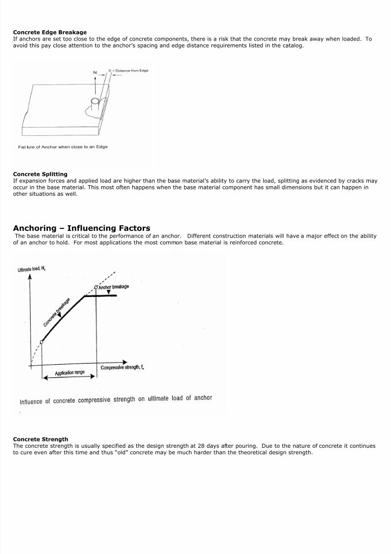
Concrete Edge Breakagef anchors are set too close to the edge of concrete components, there is a risk that the concrete may break away when loaded. void this pay close attention to the anchor’s spacing and edge distance requirements listed in the catalog.
Concrete Splittingf expansion forces and applied load are higher than the base material’s ability to carry the load, splitting as evidenced by cracks ccur in the base material. This most often happens when the base material component has small dimensions but it can happen in
ther situations as well.
Anchoring – Influencing FactorsThe base material is critical to the performance of an anchor. Different construction materials will have a major effect on the abf an anchor to hold. For most applications the most common base material is reinforced concrete.
Concrete Strengthhe concrete strength is usually specified as the design strength at 28 days after pouring. Due to the nature of concrete it contino cure even after this time and thus “old” concrete may be much harder than the theoretical design strength.
8/22/2019 WEJIT t 719 Techmanual
http://slidepdf.com/reader/full/wejit-t-719-techmanual 20/33
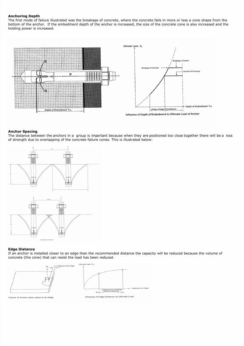
Anchoring Depthhe first mode of failure illustrated was the breakage of concrete, where the concrete fails in more or less a cone shape from theottom of the anchor. If the embedment depth of the anchor is increased, the size of the concrete cone is also increased and theolding power is increased.
Anchor Spacinghe distance between the anchors in a group is important because when they are positioned too close together there will be a lof strength due to overlapping of the concrete failure cones. This is illustrated below:
dge Distancef an anchor is installed closer to an edge than the recommended distance the capacity will be reduced because the volume of oncrete (the cone) that can resist the load has been reduced.
8/22/2019 WEJIT t 719 Techmanual
http://slidepdf.com/reader/full/wejit-t-719-techmanual 21/33
ReinforcementMost product application data is from testing in un-reinforced concrete, which means that the results may be conservative.Research work has shown that reinforcement has no significant effect on the ultimate load of an anchor unless the reinforcement pecifically placed for that purpose. Reinforcement does reduce the effects of edge breakage and also reduces the widths of oncrete cracks where that phenomenon is seen.
Anchoring – LoadingCommon engineering usually focuses on static loads however focusing solely on that aspect of loading can yield misleading resultsnd can cause the under designing of an anchoring system
Static Loadstatic loads can be segregated as follows:
An objects own (dead) weight
Permanent Loads – Loads of non-load bearing components such as floor covering, screed, or from constraint (due totemperature change or sinking of supports/columns)
Changing Loads – Such as working loads like fitting and furnishings, machines, normal wear, snow, wind, temperature
Dynamic Loadshe main difference between static and dynamic loads is the effectiveness of inertia and damping forces. These forces result innduced acceleration and must be taken into account when determining section forces and anchoring forces. Dynamic loads canypically be classified into 3 different groups:
Fatigue loads Seismic loads Shock loads
atigue loads are normally classified into two sub groupings. – Vibration loading of anchors with very high recurrence and usually low amplitude such as ventilators, production machinery, e – Repeated loading and unloading of structures with high loads and frequent recurrence such as elevators, cranes and robots.
oading that causes fatigue have a large number of load cycles which produce changes in stress in the effected fastening. Thesetresses result in a decrease of strength, which is all the greater the larger the change in stress and the larger the number of loadycles (fatigue). When evaluating loads causing fatigue, not only the type of load but also the planned or anticipated fastening lifxpectancy is of major importance.
Seismic loads are a well publicized phenomenon.Generally, all fastening situated in structures located in seismically active regions and areas can be subject to seismic loading.
However, due to cost considerations, usually only critical fastenings whose failure would result in loss of life or significant weakenf the over all structure are designed for seismic loads.
Ground movement during an earthquake or seismic tremors lead to relative displacement of a building foundation. The inertia of uilding’s mass makes it difficult or impossible for this movement to occur without deformation or damage. Due to the stiffness ohe structure restoring forces are created and vibration is induced. This results in stress and strain for the structure and the partastened and to the fastener installations. Earthquake frequencies often lead to resonance phenomena which cause larger vibratimplitudes on the upper floors.n view of the low ductility of anchor and fasteners, seismic loads generally have to be taken up by a high loading capacity and vettle deformation. A fastening should be able to withstand and be designed for use in earthquake zones without damage.
Determining the forces acting on a fastening is difficult and should be done only by qualified professionals.
Shock loads are mostly unusual loading situations even though they are the only loading a structure may be designed forwithstanding such as crash barriers, avalanches, falling rocks, protection nets, ship or airplane impacts or explosions.hock phenomenon generally have a very short duration and tremendously high forces that occur in individual peaks. Since therobability of one of these occurrences happening in the life expectancy of the building components concerned is relatively smalllastic deformations of fasteners and structural members are usually permitted.
Material Behavior - Material behavior under static loading is described primarily by strength such as tensile and compressive anhe elastic behavior of the material. These properties are generally determined by carrying out simple tests with specimens.
Material behavior under fatigue impact – If a material is subject to a sustained load that changes with respect to time, it can fail acertain number of load cycles even though the upper limit of the load withstood up to this time, is clearly lower than the ultimate
ensile strength under static loading. This loss of strength is referred to as material fatigue.he grade and quality of the steel has a considerable influence on the alternating strength for example: In the case of structurand heat-treatable steels, the final strength is approximately 25% – 35 % of the static strength after 2 million loadycles or more. n the non-loaded state, concrete already has micro cracks in the zone of contact of the aggregate and the cement paste which arttributable to the aggregate hindering shrinkage of the cement paste. The fatigue strength of concrete is directly dependent on rade of concrete. Concrete strength is reduced to about 55% - 65% of the initial strength after 2 million load cycles.he material strength is not influenced so much under fatigue impact. Other factors such as inertia, cracks etc. influence the
ehavior much more in this case.
8/22/2019 WEJIT t 719 Techmanual
http://slidepdf.com/reader/full/wejit-t-719-techmanual 22/33
Material Behavior - Fatigue When a large number of load cycles are involved it is usually the anchor in single fastenings that aritical due to steel fatigue and failure. The concrete generally only fails when the depth of embedment is shallow and subjected ensile loading or if an anchor is at a reduced edge distance and exposed to a shear load. Individual anchors in a multi-anchorastening such as a group can have a different elastic stiffness and a displacement behavior (slip) that differs from one anchor tonother. This leads to a redistribution of forces in the anchors during the load cycle. Stiffer anchors are subjected to higher load
whereas the loads in the weaker anchors are reduced. A reduction factor for multiple anchorage or groups is generally used to alloor this phenomenon. Both mechanical and chemical anchors are basically suitable for fastenings subject to fatigue loading.
Seismic Quake - Anchors (fasteners) subjected to seismic loading can under certain circumstances be stressed far beyond theirtatic loading capacities. Due to this, the respective suitability tests are carried out using a loading that is considerably higher thahe working load level. The behavior of anchors under seismic conditions depends on the magnitude of loading, the direction of t
oading, the base material and the type of anchor. After an earthquake the loading capacity is generally considerably reduced. Wny earthquake design of fasteners, concrete cracks resulting from the seismic activity should be taken into consideration.
When designing anchor fastenings it is important to remember that they can not be regarded as isolated fixings to take up seismiorces but should be considered in the overall context of the design.
Chemical anchors do well under most other seismic loading conditions. However a mechanical fastening may be more suitable undertain external conditions such as where there is a risk of fire and so on.
Shock – Shock can be simulated by mimicking load increase times and amplitude in the range of milliseconds during tests usingservo-hydraulic test equipment. The main effects observed during this testing has been:
deformation is greater when the breaking load is reached
energy absorbed by the anchorage is higher breaking loads are roughly the same magnitude during static loading and shock loading tests
uitability for shock is something that the designer must take into consideration when demanding a fastening for their applicationome adhesive and mechanical systems will work quite well and are quite suitable when load considerations and risk is properly
onsidered during the designing phase of the application.
Bending – It is frequently necessary to place shims or spacers between the fixture and the base material for alignment or levelinWhen this occurs it is often the strength of the anchor material which determines the strength of the connection. The load is app
distance from the base material creating a lever like action on the anchorage. The allowable bending load should be calculated bhe design engineer based upon the material from which the anchor is manufactured and not necessarily the tension and shearapacity of the anchor. In concrete the bending arm should be increased by ½ to 1 anchor diameter to allow for spalling around op of the anchor hole.
Cracked Concrete – AnchoringMany factors cause cracking in concrete and these cracks can reduce the anchor loading capacity by splitting the concrete cone thesists the applied load. For anchoring the cracks may be considered “dead” or “live” depending upon their cause. A dead crack ne that usually occurs during the curing process or settling process of the structure. This not a “moving” crack.
A live crack one that is still able to move and may be caused by the imposed load or foundation problems. Cracks of less thanpproximately .012” are normally considered non-structural. Wej-it has developed an anchoring system made specifically to addrehe need for fastenings in zones where cracking is likely. This system has been tested to AC 193, ACI 335,2 and met the mosttringent requirements of both acceptance criteria.
CorrosionWe dealt with corrosion in a more general way earlier in this manual. Here we shall discuss the specifics as it relates to fastenershe most common and basic coating for our fasteners is electro-plated zinc. Some still use the old reference to this process aslectro-galvanizing. Zinc is a sacrificial coating which will “heal” itself if damaged making it a desirable coating for anchors whichot generally treated with much care in the field. Electro-plated material coating thickness is governed by ASTM B-633, Type II, S
mproved corrosion resistance can be provided by the use of hot-dip galvanizing. This is a process which is exactly what its nameurports it to be, a dip in a hot bath of molten zinc. This process coats the anchor with a significantly more robust shell than othe
methods afford. Hot-dip (HDG = Hot Dip Galvanizing and NOT Heavy Duty Galvanizing which is misleading and often used wheneferring to mechanical plating) galvanizing thickness is governed by ASTM A 183, B-454 and B-695-82.
03/304 Stainless Steel affords increased corrosion protection than zinc plated & galvanized coatings.16 Stainless Steel are for fastening that face even greater risks of a higher corrosive environment. Your designer should identifypecific level of needed protection. But generally speaking 316 SS does well in places like tunnels, seawater, swimming pools, wareatment, power plants and so on. But all metals have their limits, especially in chemically aggressive environments.

8/22/2019 WEJIT t 719 Techmanual
http://slidepdf.com/reader/full/wejit-t-719-techmanual 23/33
Drill BitsA drill bit of the correct nominal diameter should always be used. Detailed below are nominal drill bit sizes that have beenoordinated with most anchor fastenings in the U.S. to provide the published anchor performance.
Anchors are designed to be used in holes in concrete and masonry base materials with carbide tipped drill bits meeting the ANSIB212.15 standard as shown above.he actual hole diameter is larger than the nominal diameter. For example, a ¾” nominal drill bit diameter has an OD (outeriameter) of .775” to .787”. When selecting the diameter of the hole to be pre-drilled, the diameter of the hole selected should aor proper anchor installation.
When going through a fixture be sure that the pre-punched or drilled hole is big enough to allow the carbide tipped masonry bit toass through. This is usually 1/16” over for sizes up to 7/8”. For sizes of 1” or larger it’s usually plus 1/8”.

8/22/2019 WEJIT t 719 Techmanual
http://slidepdf.com/reader/full/wejit-t-719-techmanual 24/33
Introduction to Anchoring Designhe design of fastenings is becoming increasingly important for both design professionals and the construction community. Post-nstalled mechanical anchors on the market today offer the potential to routinely transfer loads of relatively large magnitude intoarious base materials. Optimum use of anchors is only possible if the design explicitly considers not only the direction of the loadtension, shear or combined tension and shear) but the modes of failure as well.ffective anchor design requires careful consideration to the required loading capacity and required level of safety of the anchorag
Risk analysis is used to determine the necessary level of safety that will be required along with consideration to the use of safetyactors. These are usually specified in national or company standards and codes of practice. For example: Wej-it recommends a safety factor when using it’s mechanical anchorages such as Ankr-Tite and Original Wej-it installations.
he load capacity of an anchorage is normally determined in accordance with recognized standards or building codes, e.g. The
nternational Building Code (IBC), International Residential Code (IRC), Building Standards Law in Japan or the Eurocodes in EuroMost codes identify the holding power of an anchor installation in terms of “resistance” and the loads acting on the anchorage asactions” which are simply a convenient way to describe how an anchor works. But in any case, both resistance and actions mustonsidered when designing an anchor installation (or as our European friends like to call it, a “fixing”).
Design PhilosophyAn anchor installation should be designed giving careful consideration to the maximum known resistance that may be applied andminimum likely resistance that may be obtained. These values can then be combined to enable a probability of failure of thenchorage to be estimated and the appropriate reliability to be achieved.
Risk Analysis - Basicshe design of an appropriate anchor installation can only be achieved if the effects of anchorage failure are considered. Mostnchorage installations can be divided into 3 classes, depending on the significance of a failure:
CLASS 1
ight loads, non structural anchorages, usually multiple anchor points. Sometimes referred to redundant fastening systems, whehe failure of one or two individual anchors is not a problem and is of little cost.
CLASS 2ailure of these anchors may involve a risk to human life or considerable economic consequences. Safety anchors must be used esigned in accordance with the relevant engineering design codes.
CLASS 3n this installation any failure may involve risk to many lives and/or serious economic or social consequences. Advice should bebtained from a licensed and qualified engineer who will have all of the latest information.
Variation in Base Material PerformanceDue to the variations in material performance in both the anchor and base material e.g. concrete, the exact or absolute performaf an anchorage can only be determined by carrying out destructive testing. Usually, the load applied to an anchor during its life ot known. To allow for these unknowns, “Safety Factors” and “Characteristic Values” are applied in the design process.
Values - Basicshe loading capacities published in the manual are obtained using internationally recognized standards, test methods and test crit
When a series of anchors are tested to failure, a range of results are obtained. If enough tests are carried out it is possible to ploistogram of the results. This histogram can be approximated by the normal curve (Gaussian). The curve has a mathematicalefinition that allows areas between the limits under the curve to be calculated. By definition the total area under the curve has rea of 1 and the area between the limits under it represents the proportion of the anchorages that failed between the limits.
Unfortunately, the normal curve extends to infinity in both directions so there is always a probability of some actions being greatehan a given value and some resistances being less than the same value. The probability of this happening is referred to as failurrobability. The characteristic value of resistance (Rk) is defined as the load below which, theoretically, only 5% of anchors would fail.
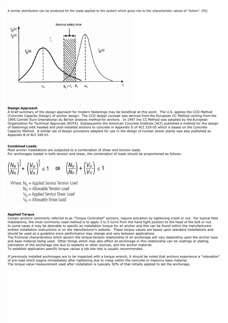
8/22/2019 WEJIT t 719 Techmanual
http://slidepdf.com/reader/full/wejit-t-719-techmanual 25/33
similar distribution can be produced for the loads applied to the system which gives rise to the characteristic values of “Action”. (Fk)
Design Approach
A brief summary of the design approach for modern fastenings may be beneficial at this point. The U.S. applies the CCD MethodConcrete Capacity Design) of anchor design. The CCD design concept was derived from the European CC Method coming from th995 Comite’ Euro-Intenational du Be’ton analysis method for anchors. In 1997 the CC Method was adopted by the European
Organization for Technical Approvals (EOTA). Subsequently the American Concrete Institute (ACI) published a method for the desf fastenings with headed and post-installed anchors to concrete in Appendix D of ACI 318-05 which is based on the Concrete
Capacity Method. A similar set of design provisions adapted for use in the design of nuclear power plants was also published asAppendix B of ACI 349-01.
Combined LoadsMost anchor installations are subjected to a combination of shear and tension loads.or anchorages loaded in both tension and shear, the combination of loads should be proportioned as follows:
Applied TorqueCertain anchors commonly referred to as “Torque Controlled” anchors, require actuation by tightening a bolt or nut. For typical finstallations, the most commonly used method is to apply 3 to 5 turns from the hand tight position to the head of the bolt or nut.
n some cases it may be desirable to specify an installation torque for an anchor and this can be found within the manufacturerswritten installation instructions or on the manufacturer’s website. These torque values are based upon standard installations andhould be used as a guideline since performance may change and vary between applications.he frictional characteristics which govern the torque-tension relationship of an anchorage will vary depending upon the anchor tynd base material being used. Other things which may also effect an anchorage in this relationship can be coatings or plating,ubrication of the anchorage site due to sealants or other sources, and the anchor material.o establish application specific torque values a job site test is usually recommended.
f previously installed anchorages are to be inspected with a torque wrench, it should be noted that anchors experience a “relaxatf pre-load which begins immediately after tightening due to creep within the concrete or masonry base material.he torque value measurement used after installation is typically 50% of that initially applied to set the anchorage.

8/22/2019 WEJIT t 719 Techmanual
http://slidepdf.com/reader/full/wejit-t-719-techmanual 26/33
Working Load
vidence of suitability is determined by comparing the recommended working load, Frec (allowable or admissible load of the anch
with the actual applied load, Fact (actual anticipated load) and requiring:
act is less than or equal to Frec - Fact < Frec
All design load that satisfy this equation are permitted)
he recommended working load is determined using the Characteristic Value of the Ultimate load of the fastener, Rk. and the GlobalSafety Factor v ;
R k
F rec = v
he global safety factor v allows for uncertainties in all the factors influencing fastener installation, setting, placement, local base materialariations as well as peak loads and long term effects. Its value may vary with each anchorage but it is generally in the range of 2.5 to 4.
While this is a simple approach it can also be a restrictive one.
nother approach to design safety is based on a semi-problematic fastening design. The Design Load (factored load), Fd, must not exce
he Design Resistance (factored characteristic load of the anchor), R d,
artial safety factor Yf and Ym allow for the uncertainty of the applied loads and inaccuracies when defining limiting conditions.Greater degrees of safety can be associated with critical parts of design.
he two design approaches can be compared if the equations noted above are arranged in terms of Fk. then:
rom this it can be seen that:
Which establishes the link between the two safety concepts. For design purposes, the actual or un-factored load acting on the ans:

8/22/2019 WEJIT t 719 Techmanual
http://slidepdf.com/reader/full/wejit-t-719-techmanual 27/33
As I said earlier the current international state of the art regarding the design of fasteners, the so called concrete capacity methodsed as the basis for this manual information. This design method was simplified but we are trying to retain as much as possible ohe previous design method, while including as much of the latest design approach as possible.
he main features of this design method are:
Differentiation between failure modes: Pull out, concrete or steel failure. (The different failure modes which occur when thanchor is loaded to failure are treated separately)
Differentiation of the safety factors based upon different failure modes.
he benefits of this approach are:
The new method reflects the actual anchor behavior in a more accurate fashion, thus leading to higher loads with certain
applications. The differentiation between failure modes allows flexibility with regard to the steel elements without the need to perform
new design calculation.
The given data are in conformance with design codes, such as ETAG Annex 6 and ACI 318 chapter 22.
New Design MethodA distinction is made between 3 failure modes with this type of design approach, namely the combination pull out failure, concreteailure and failure of the steel element. The following chart shows the flow of required calculations:

8/22/2019 WEJIT t 719 Techmanual
http://slidepdf.com/reader/full/wejit-t-719-techmanual 28/33
hear Resistance:A distinction is made between two types of failure modes with this design approach, namely concrete edge failure. i.e. breaking af the concrete members edge and the shear failure of the steel element. The following chart shows the flow of required calculat
he load value Vo Rd,c is taken as a resistance of a concrete component edge to a single anchor fastening at the minimum edge
istance, Cmin, and with the lowest concrete strength covered in the product information as well as applied shear force acting
erpendicular to the free edge of the concrete member.
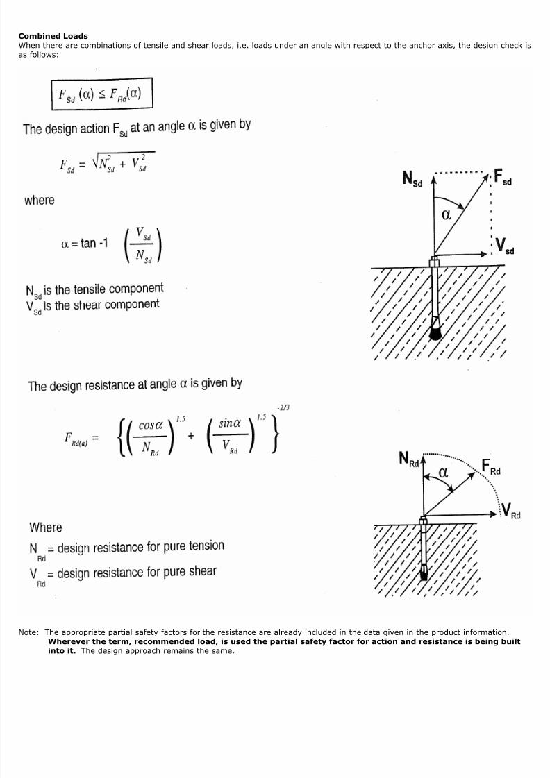
8/22/2019 WEJIT t 719 Techmanual
http://slidepdf.com/reader/full/wejit-t-719-techmanual 29/33
Combined LoadsWhen there are combinations of tensile and shear loads, i.e. loads under an angle with respect to the anchor axis, the design checs follows:
Note: The appropriate partial safety factors for the resistance are already included in the data given in the product information.Wherever the term, recommended load, is used the partial safety factor for action and resistance is being buiinto it. The design approach remains the same.

8/22/2019 WEJIT t 719 Techmanual
http://slidepdf.com/reader/full/wejit-t-719-techmanual 30/33
Concrete Resistance CCD Method
TENSION:
Concrete Cone Resistance ( N rd,c )
he design concrete cone resistance is calculated from the characteristic resistance NoRk,c
By NoRd,c = No
Rk,c / YM,c where YM,c is the partial safety factor for concrete. The influenced design concrete cone is given;
N Rd,c = NoRd,c * f B * f T * f A,N * f R,N where No
Rd,c accounts for the basic resistance in a certain concrete strength, for a stand
mbedment depth without any influence of edge distance and anchor spacing
B accounts for the influence of concrete strength
T accounts for the influence of embedment depthActual Embedment Depth
A,N accounts for the influence of spacing between the anchorsActual Anchor Spacing

8/22/2019 WEJIT t 719 Techmanual
http://slidepdf.com/reader/full/wejit-t-719-techmanual 31/33
R,N accounts for the distance from the edge
Actual Edge Distance
SHEAR:
he concrete edge distance is calculated from the characteristic resistance VoRk,c by Vo
Rd,c = VoRk,c/YM,c is the partial safety fa
or concrete. The factors are given under each product sections. The influenced design concrete edge resistance is given by:
VRd,c = VoRd,c * f B * f AR,v * f β,v where
VoRd,c accounts for the concrete edge resistance at the minimum edge distance for a certain concrete strength
B accounts for the influence of the concrete strength
AR,v accounts for the influence of anchor spacing and edge distance
he white area provides the concrete resistance; when s>3c anchors do NOT influence each other.As the edge distance increases the edge resistance increases.

8/22/2019 WEJIT t 719 Techmanual
http://slidepdf.com/reader/full/wejit-t-719-techmanual 32/33
β,v accounts for the influence of load direction
Sample Equations:

8/22/2019 WEJIT t 719 Techmanual
http://slidepdf.com/reader/full/wejit-t-719-techmanual 33/33