Weijia Tao Hierarchical Kinematic Design of Foldable ...
11
Siamak G. Faal Soft Robotics Laboratory, Department of Mechanical Engineering, Worcester Polytechnic Institute, 100 Institute Road, Worcester, MA 01609 e-mail: [email protected] Fuchen Chen Soft Robotics Laboratory, Department of Mechanical Engineering, Worcester Polytechnic Institute, 100 Institute Road, Worcester, MA 01609 e-mail: [email protected] Weijia Tao Soft Robotics Laboratory, Department of Mechanical Engineering, Worcester Polytechnic Institute, 100 Institute Road, Worcester, MA 01609 e-mail: [email protected] Mahdi Agheli Soft Robotics Laboratory, Department of Mechanical Engineering, Worcester Polytechnic Institute, 100 Institute Road, Worcester, MA 01609 e-mail: [email protected] Shadi Tasdighikalat Soft Robotics Laboratory, Department of Mechanical Engineering, Worcester Polytechnic Institute, 100 Institute Road, Worcester, MA 01609 e-mail: [email protected] Cagdas D. Onal 1 Soft Robotics Laboratory, Department of Mechanical Engineering, Worcester Polytechnic Institute, 100 Institute Road, Worcester, MA 01609 e-mail: [email protected] Hierarchical Kinematic Design of Foldable Hexapedal Locomotion Platforms Origami-inspired folding enables integrated design and manufacturing of intricate kine- matic mechanisms and structures. Here, we present a hierarchical development process of foldable robotic platforms as combinations of fundamental building blocks to achieve arbitrary levels of complexity and functionality. Rooted in theoretical linkage kinematics, designs for static structures and functional units, respectively, offer rigidity and mobility for robotic systems. The proposed approach is demonstrated on the design, fabrication, and experimental verification of three distinct types of hexapedal locomotion platforms covering a broad range of features and use cases. [DOI: 10.1115/1.4030468] 1 Introduction Mechatronic and robotic development demands new design and fabrication techniques for mechanical systems to address open challenges regarding the assembly process, speed, and cost of tra- ditional approaches. Advances in electronics and reduced size of components provide a potential to combine the mechanical and electrical subsystems in a unified assembly process. While layer- by-layer 3D printing can fabricate highly complicated parts and assemblies, the manufacturing and assembly processes are time- consuming and costly, while circuit integration remains a signifi- cant challenge. As a potential solution, origami-inspired foldable structures are fabricated from thin sheets of raw material using planar manufacturing and subsequent folding techniques [1–3]. The process includes cutting a crease pattern and folding the structure based on given blueprints. Cutting the crease patterns through the sheet of material, which is usually performed with laser cutters, is a rapid and inexpensive process. Also, the material sheets in flat form can be equipped with electrical components before assembly. This will significantly reduce the storage and shipping volume of the products. Application of origami-inspired foldable structures enables the construction of complicated assem- blies that contain both mechanical and electrical components. As a consequence, robotic systems with fully integrated circuitry and motion transmission elements can be developed from scratch at scales and volumes not achievable by existing techniques. With the advances in self folding structures [4–8], folding can happen through a human-independent process. Thus, fabrication methods that involve folding are a promising solution for fast and inexpensive on-demand productions. A significant problem 1 Corresponding author. Manuscript received August 16, 2014; final manuscript received April 15, 2015; published online August 18, 2015. Assoc. Editor: Aaron M. Dollar. Journal of Mechanisms and Robotics FEBRUARY 2016, Vol. 8 / 011005-1 Copyright V C 2016 by ASME Downloaded From: http://mechanismsrobotics.asmedigitalcollection.asme.org/ on 08/19/2015 Terms of Use: http://www.asme.org/about-asme/terms-of-use
Transcript of Weijia Tao Hierarchical Kinematic Design of Foldable ...
Siamak G. FaalSoft Robotics Laboratory,
Department of Mechanical Engineering,
Worcester Polytechnic Institute,
100 Institute Road,
Worcester, MA 01609
e-mail: [email protected]
Fuchen ChenSoft Robotics Laboratory,
Department of Mechanical Engineering,
Worcester Polytechnic Institute,
100 Institute Road,
Worcester, MA 01609
e-mail: [email protected]
Weijia TaoSoft Robotics Laboratory,
Department of Mechanical Engineering,
Worcester Polytechnic Institute,
100 Institute Road,
Worcester, MA 01609
e-mail: [email protected]
Mahdi AgheliSoft Robotics Laboratory,
Department of Mechanical Engineering,
Worcester Polytechnic Institute,
100 Institute Road,
Worcester, MA 01609
e-mail: [email protected]
Shadi TasdighikalatSoft Robotics Laboratory,
Department of Mechanical Engineering,
Worcester Polytechnic Institute,
100 Institute Road,
Worcester, MA 01609
e-mail: [email protected]
Cagdas D. Onal1Soft Robotics Laboratory,
Department of Mechanical Engineering,
Worcester Polytechnic Institute,
100 Institute Road,
Worcester, MA 01609
e-mail: [email protected]
Hierarchical KinematicDesign of Foldable HexapedalLocomotion PlatformsOrigami-inspired folding enables integrated design and manufacturing of intricate kine-matic mechanisms and structures. Here, we present a hierarchical development processof foldable robotic platforms as combinations of fundamental building blocks to achievearbitrary levels of complexity and functionality. Rooted in theoretical linkage kinematics,designs for static structures and functional units, respectively, offer rigidity and mobilityfor robotic systems. The proposed approach is demonstrated on the design, fabrication,and experimental verification of three distinct types of hexapedal locomotion platformscovering a broad range of features and use cases. [DOI: 10.1115/1.4030468]
1 Introduction
Mechatronic and robotic development demands new design andfabrication techniques for mechanical systems to address openchallenges regarding the assembly process, speed, and cost of tra-ditional approaches. Advances in electronics and reduced size ofcomponents provide a potential to combine the mechanical andelectrical subsystems in a unified assembly process. While layer-by-layer 3D printing can fabricate highly complicated parts andassemblies, the manufacturing and assembly processes are time-consuming and costly, while circuit integration remains a signifi-cant challenge. As a potential solution, origami-inspired foldablestructures are fabricated from thin sheets of raw material using
planar manufacturing and subsequent folding techniques [1–3].The process includes cutting a crease pattern and folding thestructure based on given blueprints. Cutting the crease patternsthrough the sheet of material, which is usually performed withlaser cutters, is a rapid and inexpensive process. Also, the materialsheets in flat form can be equipped with electrical componentsbefore assembly. This will significantly reduce the storage andshipping volume of the products. Application of origami-inspiredfoldable structures enables the construction of complicated assem-blies that contain both mechanical and electrical components. Asa consequence, robotic systems with fully integrated circuitry andmotion transmission elements can be developed from scratch atscales and volumes not achievable by existing techniques.
With the advances in self folding structures [4–8], folding canhappen through a human-independent process. Thus, fabricationmethods that involve folding are a promising solution for fast andinexpensive on-demand productions. A significant problem
1Corresponding author.Manuscript received August 16, 2014; final manuscript received April 15, 2015;
published online August 18, 2015. Assoc. Editor: Aaron M. Dollar.
Journal of Mechanisms and Robotics FEBRUARY 2016, Vol. 8 / 011005-1Copyright VC 2016 by ASME
Downloaded From: http://mechanismsrobotics.asmedigitalcollection.asme.org/ on 08/19/2015 Terms of Use: http://www.asme.org/about-asme/terms-of-use

associated with foldable techniques is the design of crease pat-terns. The crease patterns need to address the geometrical as wellas mechanical requirements of the parts. This paper addresses thedesign process of simple and complex structures using a novelhierarchical approach. To assist the design process, a growinglibrary of fundamental building blocks and corresponding creasepatterns are introduced that can be combined to form increasinglycomplex units and structures. The approach discussed in this arti-cle is on semantic and functional design modulation and it is dif-ferent from design synthesis based on computational searchalgorithms that are discussed in Refs. [9,10]. As an application ofthe introduced technique, three different hexapod platforms areconsidered to address the design of simple, as well as complexstructures with multiple degrees of freedom (DOF).
To be able to perform real services, robots need to have a dex-terous and agile locomotion system. Inspired by the locomotionsystems of insects [11], hexapod platforms are a promising solu-tion to take the robots out of laboratory environments. The staticstability with enough dexterity to pass over relatively rough anduneven terrain make hexapod platforms a suitable solution foroutdoor applications [12,13]. For use as multirobot agents, fabri-cation of each one of the platforms needs to be cost- and time-effective [14,15]. To address this issue, this paper discusses threedifferent designs for foldable hexapedal locomotion platforms,namely: (1) a 2DOF platform that utilizes two 6-bar linkages onboth sides for differential steering; (2) a 3DOF mechanism thatuses three 6-bar linkages to allow the system to exhibit threedegrees of mobility (DOM) [16]; and (3) an 18DOF platform thatis composed of six, 3DOF serial linkages. The origami techniquesthat are utilized in the design process reduces the time and cost offabrication. In comparison to relatively rigid structures, the com-pliance of the materials that are used for folding and the flexibilityof folded joints allow the structures to possess an inherent suspen-sion system to absorb collisions between feet and substratesurface.
The main contributions of this paper can be outlined as: (1)marrying kinematic synthesis with origami engineering to achieverobotic mechanisms of arbitrary complexity. The applicability ofthe introduced techniques has been evidenced through the designand fabrication of three different multilegged robots, demonstrat-ing the broad range of possibilities; (2) design, fabrication, andexperimental verification of a novel holonomic 3DOF foldablelegged platform. Unlike mecanum wheels [17], the holonomiclegged architecture can be utilized on relatively rough terrain; (3)design and fabrication of an 18DOF foldable platform for serviceapplications. This paper focuses on a novel design and fabricationprocess appropriate to create origami-inspired foldable robots ofarbitrary complexity. Unlike the origami-inspired robots presentedin the literature, the introduced hierarchical design process andfunctional units, allow fabrication of folded platforms with thedesired mechanical and functional complexity according to taskspecifications. The presented robot prototypes are working exam-ples of the proposed hierarchical design process to fabricate plat-forms, utilizing open- and closed-loop kinematic chains.
The rest of the article is organized as follows. Section 2 introdu-ces the fundamental building blocks of foldable structures and dis-cusses a basic hierarchical foldable design concept. Sections 3–5cover the conceptual operation, design process, fabrication, andexperimental results of 2, 3, and 18DOF foldable hexapedal loco-motion platforms, respectively. The paper is concluded with dis-cussions and future work in Sec. 6.
2 Building Blocks of Foldable Bodies
This section discusses fundamental building blocks used todesign and fabricate foldable robotic platforms. Building blocksare categorized into two classes of: basic structures and functionalunits. Basic structures include rigid members, flexural joints, andconnectors. Functional units are specific assemblies of basic struc-tures to offer a growing variety of desired functionality.
Depending on the specific kinematic combination of basic struc-tures, functional units can replicate a complex rigid body or amechanism with specific DOF. In a hierarchical manner, the com-bination of functional units form mechanisms with arbitrarily highcomplexity.
2.1 Basic Structures. Our approach to origami-inspired fold-able design and fabrication relies heavily on a set of basic struc-tures, which include triangular hollow beams, flexural revolutejoints, key-and-slot fasteners, and insertion locks. Triangularbeams and flexures have been used extensively in multiple fields,since they are elegant formations to support loads and constructrevolute joints, respectively. Key-slot fasteners and insertion locksare essential to maintain physical integrity of the as-folded 3Dstructures. This class of basic structures is sufficient to form rela-tively simple assemblies, which may yield a single, unified creasepattern. The 2DOF hexapedal platform detailed later is an exam-ple of only utilizing basic structures in the design to achieve com-plicated kinematic linkage systems through folding. We considerthese basic structures as the fundamental building blocks neces-sary to create static structures and kinematic mechanisms usefulfor robotic systems.
2.1.1 Rigid Triangular Beams. Triangular beams are intro-duced to overcome the inherent flexibility of the thin raw materi-als (typically 0.127–0.254 mm thick plastic films [1]). Figure 1(a)illustrates an equilateral triangular beam, its corresponding creasepattern, and dimensional parameters. As discussed in Sec. 2.1.2,basic folds create flexures to replicate the behavior of revolutejoints. Thus, any hollow beam structure that has more than threesides will have positive DOF, which defeats the purpose of intro-ducing rigidity. The bending stiffness of a hollow triangular beamwith thin walls is defined as
kb ¼3Ew3t
4L3(1)
where E is the Young’s modulus (elastic modulus) of the materialused, and L, w, and t are the length, width, and thickness of eachface of the triangular beam, respectively, assuming that theembedded key-and-slot fasteners hold the shape rigidly. Thus,folding a triangular beam increases the bending stiffness of a stripof material by at least 3 orders of magnitude, which enables thetreatment of these beams as kinematic links.
2.1.2 Flexural Revolute Joints. Flexural joints are achievedby taking advantage of the inherent flexibility of thin films.Figures 1(b) and 1(c) illustrate two basic formations that approxi-mate the behavior of a revolute joint based on flexures [18]. Ashighlighted in Fig. 1(b), the dashed patterns are perforations, usedto reduce the stiffness of the material at the fold line to a fractionof the bending stiffness of a solid strip to approximate a well-defined revolute joint [2]. While many planar fabrication proc-esses are applicable, our work uses CO2 lasers for rapid andlow-cost manufacturing.
2.1.3 Key-Slot Fasteners. The main function of the key-slotfasteners is to keep the folds from unfolding, but they can be alsoused to connect or form a joint between two sections of thedesign. Different applications of the keys and slots are depicted inFig. 1. Through experimentation, we concluded that using a trape-zoidal shape for the keys significantly eases the folding process.During the insertion of a key into a slot, the two triangular sidesof the key fold back to form a smaller rectangular key. After inser-tion, the folds open again and fixes the key in the slot. The flexi-bility of the connection point depends on the length of the key andthe tolerances used during the planar design and fabricationprocess.
2.1.4 Insertion Locks. Similar to key-slot fasteners, insertionlocks are useful to secure two separate units to each other.
011005-2 / Vol. 8, FEBRUARY 2016 Transactions of the ASME
Downloaded From: http://mechanismsrobotics.asmedigitalcollection.asme.org/ on 08/19/2015 Terms of Use: http://www.asme.org/about-asme/terms-of-use

Although locks are composed of starlike keys and slots, they donot require any preassembly folding as the locking process hap-pens automatically by the insertion of the first unit with slotsinside the starlike patterned keys of the second unit. The assemblyprocess of a lock is depicted in Fig. 2. As shown in this figure, thestarlike keys penetrate into the allocated slots and fastens the unitsto each other.
2.2 Functional Units. Forming functional units from basicstructures reduces the complexity of the design process. The func-tional units do not necessarily need to be fabricated individually.
As discussed in the flowchart of Fig. 3, it might be possible tocombine the crease patterns of functional units into a unified pat-tern. On the other hand, fabricating functional units individuallycan significantly reduce the constraints in the design and assemblyprocess. Typically, the design of a unified single crease patternfrom scratch requires significant expertise, while composition offunctional units is routinely performed by novice researchers inour group. Moreover, the modular nature of functional units lendsitself to rapid modifications without redesigning the entire system.Depending on the structures used, functional units can have zero,as well as, multiple DOF. As an example, connecting three trian-gular beams to each other yields trusslike formations, which is astatic unit that can tolerate large loads. On the other hand, con-necting multiple beams and joints form linkage mechanisms,which can serve a specific purpose. Note that, with this approach,it is possible to create both serial and parallel kinematic mecha-nisms as functional units. While linkage mechanisms of any con-figuration can be achieved with our approach, we pay special
Fig. 3 Design process flow chart that represents the majorfoldable structure design steps
Fig. 1 The basic structures used in the design of the foldableplatforms. (a) The triangular beam and the correspondingcrease pattern. The cut in the beam shows how the keys andslots are used to keep the beam from unfolding. (b) Folded jointthat resembles the effect of a revolute joint. The hollow patternsare added to reduce the stiffness of the material at the joint. (c)Another method of forming a revolute joint using only a key anda slot. The cut in the beam shows the slot and the key that islocked inside it.
Fig. 2 The typical structure and assembly process of an inser-tion lock
Journal of Mechanisms and Robotics FEBRUARY 2016, Vol. 8 / 011005-3
Downloaded From: http://mechanismsrobotics.asmedigitalcollection.asme.org/ on 08/19/2015 Terms of Use: http://www.asme.org/about-asme/terms-of-use

attention to the 6-bar, as an extremely versatile motionoutput unit, which can be tuned to produce a wide range offunctions [19].
As described later, the 3DOF platform utilizes an active func-tional unit that is a 6-bar linkage. The connection of three of theseunits, forms the platform, while the static base is formed by a trussunit. Similarly, the 18DOF platform is an example of using differ-ent static units. Each static unit is a beam that is designed to holda servomotor on one side and to connect to another servomotorhorn on the other side. Connecting the three separate units formseach leg of the robot. The main body of the platform is formed bythe connection of six static units. Thus, combination of functionalunits is a promising approach to design and manufacture inte-grated robotic platforms, as described on three foldable hexapodmobile robots with case studies presented in Secs. 3–5.
2.3 Design Process. Based on the complexity of the overallstructure, it may not be feasible to construct it from a unifiedcrease pattern [20]. On the same note, it may be desirable to fabri-cate the structure form groups of subunits. This justification canbe based on the space and complexity requirements of the storageand fabrication process.
Figure 3 describes our basic design process for origami-basedfoldable mechanical systems. As depicted in this figure, the designprocess starts with structure and kinematic synthesis of the sys-tem. In this phase, the designer can omit the constraints associatedwith folding techniques in order to finalize the initial concept. Theprocess follows by decomposing the structure into functional sub-sections such as: independently actuated mechanisms, supportstructures, motor housings, etc. The next step is designing (orreusing existing) crease patterns for each one of the subsections.As discussed in Sec. 2.2, the crease pattern for each substructureis a functional unit and can be constructed from basic structuresand combinations of other functional units.
At this stage, the designer can judge on the feasibility of thedesign based on constraints related to folding techniques. If it isnot possible to construct a functional unit using folding techni-ques, either the overall design should be reconsidered, or that spe-cific unit needs to be fabricated with an alternative process andassembled as discrete components. After designing all functionalunits, the designer can explore the possibility of combining theseparate crease patterns into a unified pattern. On the other hand,if it is desirable to fabricate the assembly from discrete crease pat-terns, the next step will be designing the corresponding connec-tions and joints between the functional units using key-slotfasteners and insertion locks.
2.4 Fabrication Material. Different materials such as fiberglass [4], carbon fiber [21], and posterboard [3] have been utilized indesign and fabrication of foldable structures. Although utilizing amaterial with a relatively high stiffness improves the rigidity of thestructure, it will be a poor choice for the joints. A common approachto provide the flexibility required at the joints is to use a sandwich oftwo materials, with relatively high and low flexibilities [3,21]. Whilethe design and fabrication process can be generalized to utilize manydifferent types of raw material, in systems discussed in this article,polyethylene terephalate (PET) sheets with a thickness of 0.254 mmis considered as the main fabrication substrate. PET is relatively inex-pensive, has low density, it is an electrical insulator and easy to cutwith readily available technologies such as laser-cutter machines.
3 2DOF Hexapedal Locomotion Platform
While having more DOF may help mobile platforms to havehigher dexterity, more actuators will dramatically increase thecost and complexity of the system. This makes the platform withhigher number of active DOFs infeasible solutions, especially formultirobot applications. If the objective of the platform is to walk,turn, and maneuver over a relatively rough terrain, a legged robot
with two active DOFs will be sufficient, whereby the platform canmove and rotate by controlling the speed of noncoinciding pointsof the body. The 2DOF platform in the present implementation isdesigned based on the same principle. Two 6-bar linkages, locatedon both sides of the platform, are responsible for legged locomo-tion. The role of 6-bar linkages is to control the speed of the robot,while providing it with static stability. The static stability of thesystem is achieved by guaranteeing that three feet contact the sub-strate surface throughout the gait cycle. A fully assembled 2DOFhexapod prototype and its control electronics is illustrated inFig. 4.
3.1 Design. Six-bar linkages are realized by composing a4-bar crank-rocker with a parallelogram linkage [19]. Figure 5illustrates the complete 6-bar linkage annotated with all geometricparameters. The values assigned to these parameters are domi-nated by two factors: (1) the feasibility of the design to be fabri-cated by folding techniques; and (2) To guarantee the correct gaitpattern. An optimization problem is formulated to find the optimalvalues for the design variables that will produce the maximumforward motion of the platform. This is achieved by minimizingthe vibrations introduced to the motion due to the mismatch of thefeet velocities. A perfect gait sequence is achieved when all thevelocities of the active feet are in the same direction and parallelto the body of the platform. The active feet is defined as the linktips that are in contact with the ground. However, imposing thiscondition as a constraint to the optimization problem results in an
Fig. 4 Fully assembled 2DOF hexapod platform with on-boardcontrol electronics
Fig. 5 All the parameters associated with the kinematics of the6-bar linkage
011005-4 / Vol. 8, FEBRUARY 2016 Transactions of the ASME
Downloaded From: http://mechanismsrobotics.asmedigitalcollection.asme.org/ on 08/19/2015 Terms of Use: http://www.asme.org/about-asme/terms-of-use

empty feasible space. This conclusion has been made by runningthree different numerical optimization algorithms, from 500 dif-ferent random initial points. To avoid this problem, the objectiveof the optimization is defined to maximize the distance traveledalong the body of the robot by the active feet. The detaileddescription of the kinematics and the optimization formulations ispresented in Ref. [14]. Note that this optimization is part of thekinematic design of the robot and it is independent of the generaldesign procedure for foldable robotic systems. Here, we highlightthe most significant parts of the process.
Design variables:l1, l3, and l4
Constant values:l2¼ 20 mm, l6¼ l7¼ 15 mm, h6¼ h7¼ 0 rad,lmin¼ 5 mm: minimum feasible length of the links,lmax¼ 70 mm: maximum feasible length of the links,
Dependent variables:l5¼ 2l1
Constraints:g1 to g3: lmin � li � lmax; 8i 2 1; 3; 4f gg4 to g6: l2 � li þ e � 0;8i 2 1; 3; 4f gg7: l2 þ S�
Pi li þ e � 0 for S ¼ max l1; l3; l4f g and
i 2 1; 3; 4f g � iSf gg8: p/6� h4� 5p/6
Objective function:Cost ¼ �
Ðvma:exdt�
Ðvfa:exdt
where vma:ex and vfa:ex are the velocities of the middle andfront active feet of the platform along the x-axis, as depicted in
Fig. 5. The constant values and constraints g1, g2, g3, and g8 aredefined based on the size requirements of the prototype. Con-straints g4 to g6 are forcing l2 to remain as the crank of the mecha-nism. The Grashof condition [19] is imposed by g7. The constraintg8 is defined to keep the transmission angle in an acceptablerange. To perform the optimization, two different optimizationalgorithms available in MATLAB software are used: the gradientbased optimization and genetic algorithm. Due to the nonlinearnature of the problem, the numerical algorithms can not satisfyglobal optimality [22]. Thus, the optimization code is evaluatedfrom different initial values to attain a set of solutions. After com-paring the solutions, the one that has the minimum cost value ischosen as the final result.
Figure 6 illustrates the velocities of the front and middle feet,along the x-axis as functions of the crank angle, h2 for the finalmechanism. Solid lines are used to indicate the state of the foot asbeing active. The blue and green colors are used to indicate thevelocities of the front and rear feet, respectively. Since there areno constraints on the direction of the velocities during contact,there is an interval where the active foot has a negative velocity.Although this interval will cause jittering on the movement of theplatform, the total integral of the velocities of the active feet forthe optimal solution is considerably larger than zero. This meansthe platform will have a net displacement in the forward directionat each full rotation of the crank.
The crease pattern of the 2DOF hexapod is depicted in Fig. 7.Since this platform is designed by only utilizing simple structures,the final formation has a unified crease pattern. In this figure, solidblack lines illustrate the cut lines, while the fold lines are illus-trated by dotted red lines. Four triangular beams at each side ofthe base are used to provide it with the required rigidity. The two6 bar mechanisms also utilize triangular folded beams as rigidlinks to offer the necessary strength under load.
3.2 Fabrication and Experimental Results. The fabricationprocess starts with laser machining the crease pattern on a sheet ofPET with 0.254 mm thickness. Laser cutting the full pattern takesapproximately 6 min. After cutting, the process continues by fold-ing the crease pattern and assembling the external componentssuch as DC-motors and control electronics. The overall manufac-turing process takes less than 30 min. Nylon bands are used tocover the feet to increase traction.
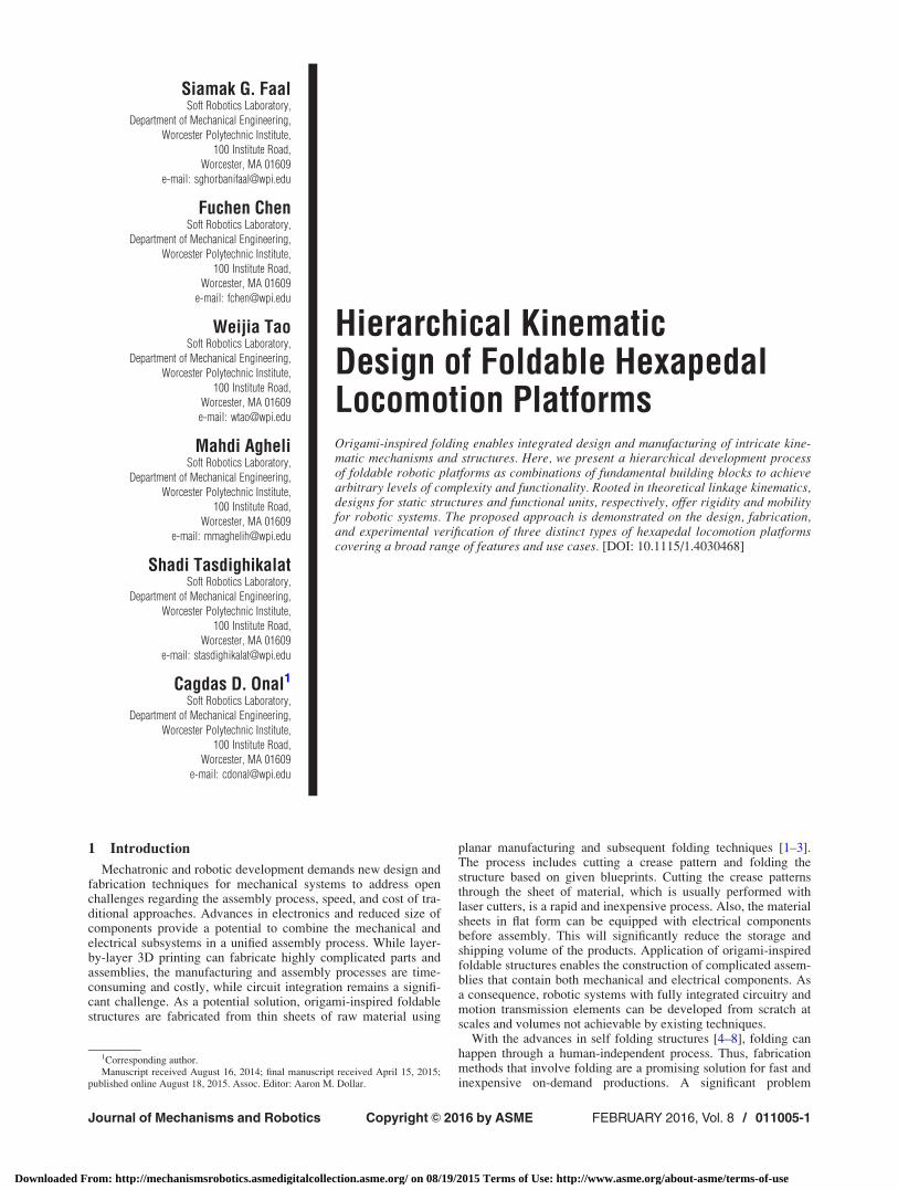
A series of tests are conducted to validate the performance ofthe platform. The platform achieved a maximum forward velocityof 5 body lengths per second (approximately 0.5 m/s). It isobserved that the forward velocity varies between this maximumspeed and approximately half of the maximum speed due to a lackof synchronization between the left and right mechanisms. Thislack of synchronization causes the gait sequence to periodicallydeviate from the tripod gait algorithm. This issue can be resolvedby a suitable feedback control algorithm that synchronizes thespeed of the two actuators. Figure 8 shows snapshots of the robot
Fig. 6 The front (positive peak on the right) and middle (posi-tive peak on the left) feet velocities along the x-axis. The solidlines represent the state of a feet as being active. Blue andgreen lines indicate the velocities of the front and middle foot,respectively.
Fig. 7 The crease pattern of the 2DOF foldable hexapod robot. Solid and dotted lines indi-cate cut and fold lines, respectively.
Journal of Mechanisms and Robotics FEBRUARY 2016, Vol. 8 / 011005-5
Downloaded From: http://mechanismsrobotics.asmedigitalcollection.asme.org/ on 08/19/2015 Terms of Use: http://www.asme.org/about-asme/terms-of-use
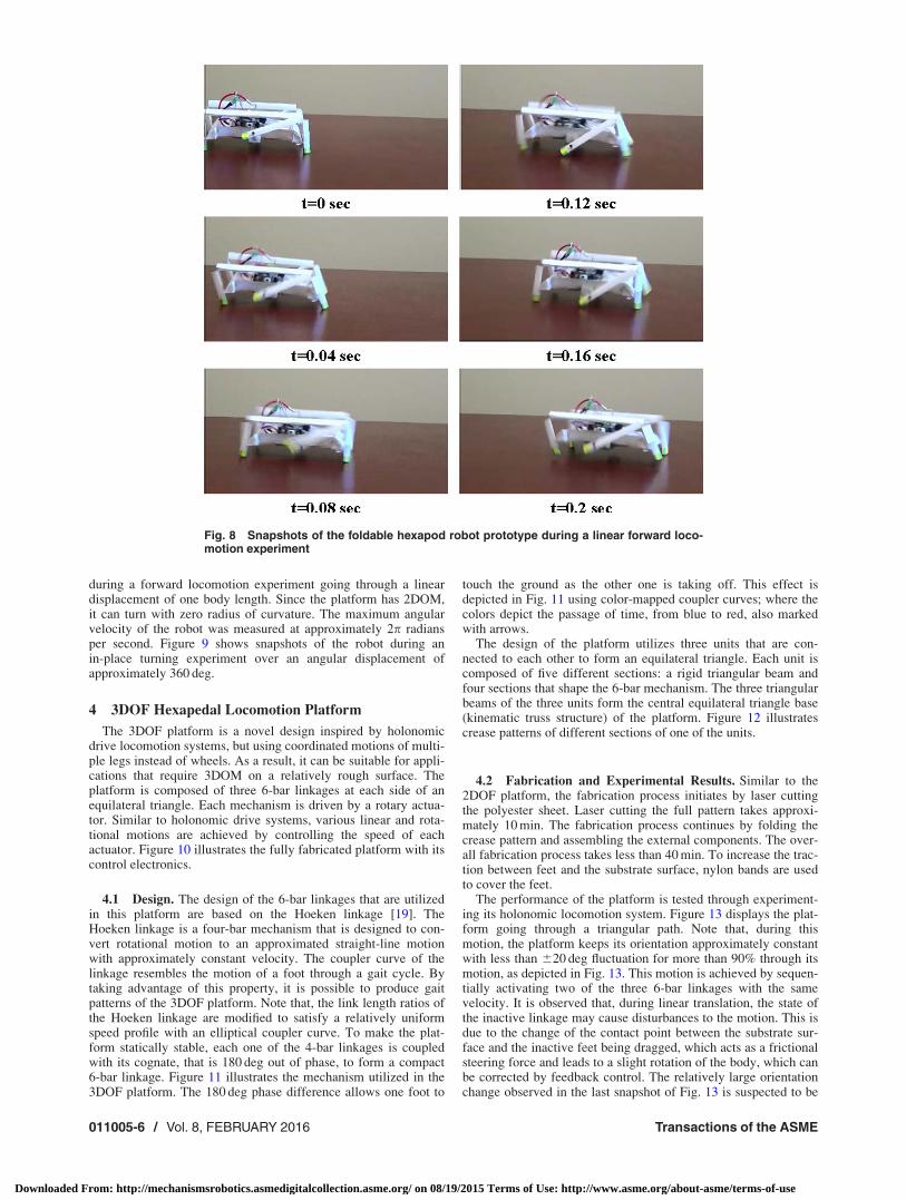
during a forward locomotion experiment going through a lineardisplacement of one body length. Since the platform has 2DOM,it can turn with zero radius of curvature. The maximum angularvelocity of the robot was measured at approximately 2p radiansper second. Figure 9 shows snapshots of the robot during anin-place turning experiment over an angular displacement ofapproximately 360 deg.
4 3DOF Hexapedal Locomotion Platform
The 3DOF platform is a novel design inspired by holonomicdrive locomotion systems, but using coordinated motions of multi-ple legs instead of wheels. As a result, it can be suitable for appli-cations that require 3DOM on a relatively rough surface. Theplatform is composed of three 6-bar linkages at each side of anequilateral triangle. Each mechanism is driven by a rotary actua-tor. Similar to holonomic drive systems, various linear and rota-tional motions are achieved by controlling the speed of eachactuator. Figure 10 illustrates the fully fabricated platform with itscontrol electronics.
4.1 Design. The design of the 6-bar linkages that are utilizedin this platform are based on the Hoeken linkage [19]. TheHoeken linkage is a four-bar mechanism that is designed to con-vert rotational motion to an approximated straight-line motionwith approximately constant velocity. The coupler curve of thelinkage resembles the motion of a foot through a gait cycle. Bytaking advantage of this property, it is possible to produce gaitpatterns of the 3DOF platform. Note that, the link length ratios ofthe Hoeken linkage are modified to satisfy a relatively uniformspeed profile with an elliptical coupler curve. To make the plat-form statically stable, each one of the 4-bar linkages is coupledwith its cognate, that is 180 deg out of phase, to form a compact6-bar linkage. Figure 11 illustrates the mechanism utilized in the3DOF platform. The 180 deg phase difference allows one foot to
touch the ground as the other one is taking off. This effect isdepicted in Fig. 11 using color-mapped coupler curves; where thecolors depict the passage of time, from blue to red, also markedwith arrows.
The design of the platform utilizes three units that are con-nected to each other to form an equilateral triangle. Each unit iscomposed of five different sections: a rigid triangular beam andfour sections that shape the 6-bar mechanism. The three triangularbeams of the three units form the central equilateral triangle base(kinematic truss structure) of the platform. Figure 12 illustratescrease patterns of different sections of one of the units.
4.2 Fabrication and Experimental Results. Similar to the2DOF platform, the fabrication process initiates by laser cuttingthe polyester sheet. Laser cutting the full pattern takes approxi-mately 10 min. The fabrication process continues by folding thecrease pattern and assembling the external components. The over-all fabrication process takes less than 40 min. To increase the trac-tion between feet and the substrate surface, nylon bands are usedto cover the feet.
The performance of the platform is tested through experiment-ing its holonomic locomotion system. Figure 13 displays the plat-form going through a triangular path. Note that, during thismotion, the platform keeps its orientation approximately constantwith less than 620 deg fluctuation for more than 90% through itsmotion, as depicted in Fig. 13. This motion is achieved by sequen-tially activating two of the three 6-bar linkages with the samevelocity. It is observed that, during linear translation, the state ofthe inactive linkage may cause disturbances to the motion. This isdue to the change of the contact point between the substrate sur-face and the inactive feet being dragged, which acts as a frictionalsteering force and leads to a slight rotation of the body, which canbe corrected by feedback control. The relatively large orientationchange observed in the last snapshot of Fig. 13 is suspected to be
Fig. 8 Snapshots of the foldable hexapod robot prototype during a linear forward loco-motion experiment
011005-6 / Vol. 8, FEBRUARY 2016 Transactions of the ASME
Downloaded From: http://mechanismsrobotics.asmedigitalcollection.asme.org/ on 08/19/2015 Terms of Use: http://www.asme.org/about-asme/terms-of-use
due to an external disturbance caused by irregularities on the sub-strate surface.
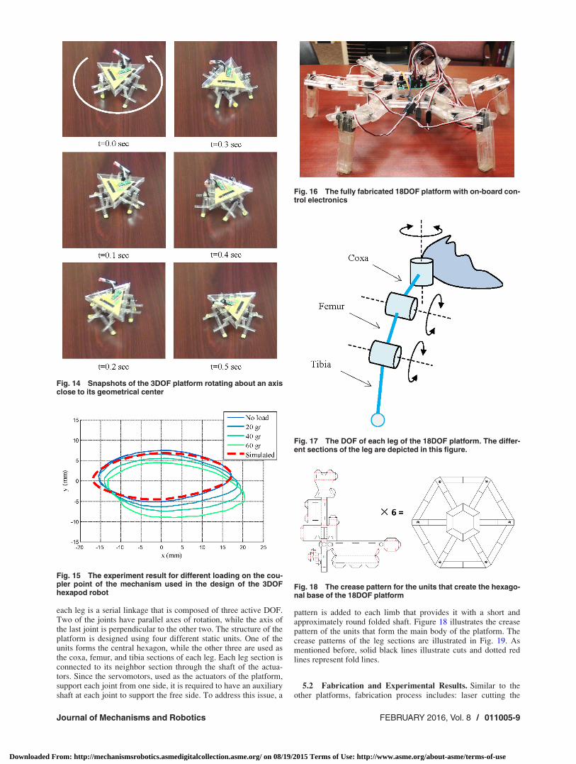
Similarly, the platform is capable of purely rotational motionsby turning all three actuators in the same direction. Rotational per-formance was experimentally tested and the maximum angularvelocity output was measured to be approximately 18 revolutionsper minute. Figure 14 illustrates the 3DOF platform as it is rotat-ing about an axis close to its geometrical center.
4.2.1 3DOF Mechanism Under Different Loading Conditions.The performance of the 3DOF robot mechanism for differentloading conditions is tested experimentally. The experimentalsetup is composed of the folded 3DOF platform and a motion cap-turing system to record the motion of the tested foot. To conductthe experiment, the body of the robot is secured to a rigid surfacewith the legs pointing upward. Different weights of 20 g, 40 g, and60 g are mounted on one of the feet sequentially to replicate theeffect of the forces exerted to one of the legs during robot locomo-tion. Since the total mass of the robot is 59.2 g, and the totalweight of the robot is supported by at least three legs, the weight
values approximately represent total payloads of 1, 2, and 3 bodyweights. Figure 15 illustrates the results of this experiment. Asobserved in the figure, the mechanism reproduces the simulatedcoupler curve under no-load condition. As the amount of payloadincreases, the coupler curves shift toward positive x-axis (awayfrom the other foot) and negative y-axis (gravity direction), i.e.,payloads act to move the two feet apart from each other, asexpected. The shifting effects are due to the moments and torsionsexerted on the triangular beam of the base of the robot and indi-cate an inherent compliance that may act as a passive suspensionsystem, which is a subject of further analysis in future work.
5 18DOF Hexapedal Locomotion Platform
The 18DOF hexapod platforms are interesting due to their highnumber of active DOF. The main body of the 18DOF hexapod is
Fig. 9 Snapshots of the foldable hexapod robot prototype during an in-place turningexperiment
Fig. 10 Fully fabricated 3DOF hexapod platform with on-boardcontrol electronics
Fig. 11 The 6-bar mechanism that is used as the feet of the3DOF platform. The shading of the coupler curves representthe passage of time. The arrows indicate motion direction.
Journal of Mechanisms and Robotics FEBRUARY 2016, Vol. 8 / 011005-7
Downloaded From: http://mechanismsrobotics.asmedigitalcollection.asme.org/ on 08/19/2015 Terms of Use: http://www.asme.org/about-asme/terms-of-use

enclosed by six legs that each has 3DOF in a bisymmetric fashion.Thus, the main body has 6DOF in Cartesian space. Being able tohave any orientation and position with respect to a fixed coordi-nate frame [23], makes 18DOF platforms a suitable solution forsurveillance, remote sensing, manipulation, and many other
applications. The fully fabricated foldable 18DOF platform withthe on-board control electronics is illustrated in Fig. 16.
5.1 Design. The DOF and different sections of one of the legsof the platform are illustrated in Fig. 17. As seen in this figure,
Fig. 12 (a) The crease patterns of the different sections of one of the units thatform the 3DOF platform and (b) a 3D illustration of the folded patterns
Fig. 13 Snapshots of the 3DOF hexapod platform going through a triangular path (depictedby arrows on the top row) by keeping its orientation (depicted by white lines) relatively con-sistent. Range of orientation changes due to imbalances in the body structure are depictedas an arc.
011005-8 / Vol. 8, FEBRUARY 2016 Transactions of the ASME
Downloaded From: http://mechanismsrobotics.asmedigitalcollection.asme.org/ on 08/19/2015 Terms of Use: http://www.asme.org/about-asme/terms-of-use
each leg is a serial linkage that is composed of three active DOF.Two of the joints have parallel axes of rotation, while the axis ofthe last joint is perpendicular to the other two. The structure of theplatform is designed using four different static units. One of theunits forms the central hexagon, while the other three are used asthe coxa, femur, and tibia sections of each leg. Each leg section isconnected to its neighbor section through the shaft of the actua-tors. Since the servomotors, used as the actuators of the platform,support each joint from one side, it is required to have an auxiliaryshaft at each joint to support the free side. To address this issue, a
pattern is added to each limb that provides it with a short andapproximately round folded shaft. Figure 18 illustrates the creasepattern of the units that form the main body of the platform. Thecrease patterns of the leg sections are illustrated in Fig. 19. Asmentioned before, solid black lines illustrate cuts and dotted redlines represent fold lines.
5.2 Fabrication and Experimental Results. Similar to theother platforms, fabrication process includes: laser cutting the
Fig. 14 Snapshots of the 3DOF platform rotating about an axisclose to its geometrical center
Fig. 15 The experiment result for different loading on the cou-pler point of the mechanism used in the design of the 3DOFhexapod robot
Fig. 16 The fully fabricated 18DOF platform with on-board con-trol electronics
Fig. 17 The DOF of each leg of the 18DOF platform. The differ-ent sections of the leg are depicted in this figure.
Fig. 18 The crease pattern for the units that create the hexago-nal base of the 18DOF platform
Journal of Mechanisms and Robotics FEBRUARY 2016, Vol. 8 / 011005-9
Downloaded From: http://mechanismsrobotics.asmedigitalcollection.asme.org/ on 08/19/2015 Terms of Use: http://www.asme.org/about-asme/terms-of-use
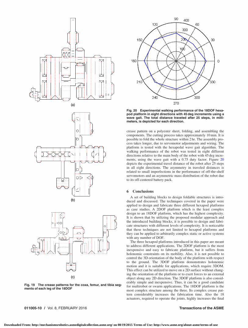
crease pattern on a polyester sheet, folding, and assembling thecomponents. The cutting process takes approximately 10 min. It ispossible to fold the whole structure within 2 hr. The assembly pro-cess takes longer, due to servomotor adjustments and wiring. Theplatform is tested with the hexapedal wave gait algorithm. Thewalking performance of the robot was tested in eight differentdirections relative to the main body of the robot with 45 deg incre-ments, using the wave gait with a 0.75 duty factor. Figure 20depicts the experimental travel distance of the robot after 25 stepsin all eight directions. The asymmetry in traveled distances isrelated to small imperfections in the performance of off-the-shelfservomotors and an asymmetric mass distribution of the robot dueto its off-centered battery pack.
6 Conclusions
A set of building blocks to design foldable structures is intro-duced and discussed. The techniques covered in the paper wereapplied to design and fabricate three different hexapod platformsas case studies. A 2DOF platform which is the least complexdesign to an 18DOF platform, which has the highest complexity.It is shown that by utilizing the proposed modular approach andthe introduced building blocks, it is possible to design and fabri-cate structures with different levels of complexity. It is noticeablethat these techniques are not limited to hexapod platforms andthey can be applied to arbitrarily complex static or active systemswith any number of DOF.
The three hexapod platforms introduced in this paper are meantto address different applications. The 2DOF platform is the mostinexpensive and easy to fabricate platform, but it suffers fromholonomic constraints on its mobility. Also, it is not possible tocontrol the 3D orientation of the body of the platform with respectto the ground. The 3DOF platform demonstrates holonomicmotion and it is suitable for applications, which require 3DOM.This effect can be utilized to move on a 2D surface without chang-ing the orientation of the platform or to exert forces to an externalobject along any 2D direction. The 3DOF platform is also consid-erably simple and inexpensive. Thus, it can be a good candidatefor multirobot or swarm applications. The 18DOF platform is themost complex structure among the three. Its complex crease pat-tern considerably increases the fabrication time. Also the 18actuators, required to operate the joints, highly increases the final
Fig. 19 The crease patterns for the coxa, femur, and tibia seg-ments of each leg of the 18DOF
Fig. 20 Experimental walking performance of the 18DOF hexa-pod platform in eight directions with 45 deg increments using awave gait. The total distance traveled after 25 steps, in milli-meters, is depicted for each direction.
011005-10 / Vol. 8, FEBRUARY 2016 Transactions of the ASME
Downloaded From: http://mechanismsrobotics.asmedigitalcollection.asme.org/ on 08/19/2015 Terms of Use: http://www.asme.org/about-asme/terms-of-use

cost and the power consumption of the system. On the other hand,the main body of the 18DOF platform has 6DOF in Cartesianspace and can have any pose, position, and orientation, withrespect to a fixed frame. Thus, this platform is suitable for surveil-lance and remote sensing applications, where it is needed to adjusta probe in a specific pose, for example.
The advantages of using foldable structures can be summarizedas: low cost, fast and straightforward fabrication process, andstructural compliance of the final product. Similar to any otherfabrication method, foldable structures suffer from some limita-tions as well. The complexity of the crease patterns increases withthe number of DOF of the system, making it difficult to designsystems with high number of DOF to be fabricated from a unifiedcrease pattern. The complexity of the crease pattern also makes itdifficult to scale the design to different dimensions. Althoughfoldable techniques can simplify the fabrication process of manysystems, it may not be the most efficient solution for some appli-cations. Most significantly, due to the nature of a fold, it isextremely difficult to have folded links that go through a full rota-tion. Thus, utilizing foldable techniques to design systems thathave many parts going through full circular rotations is not trivial.In addition, the flexibility of the folded structure reduces the preci-sion of the mechanisms. Although this flexibility highly helpswith legged locomotion systems, it is an undesired feature for pre-cision applications, such as manipulation. Ultimately, the pro-posed approach is a novel tool for the design and fabrication offuture robotic systems to be incorporated with existingapproaches, when advantageous for the requirements of thespecific application.
References[1] Onal, C. D., Wood, R. J., and Rus, D., 2011, “Towards Printable Robotics:
Origami-Inspired Planar Fabrication of Three-Dimensional Mechanisms,”IEEE International Conference on Robotics and Automation (ICRA), Shanghai,May 9–13, pp. 4608–4613.
[2] Onal, C. D., Wood, R. J., and Rus, D., 2012, “An Origami-Inspired Approachto Worm Robots,” IEEE Trans. Mechatronics, 18(2), pp. 430–438.
[3] Hoover, A. M., and Fearing, R. S., 2008, “Fast Scale Prototyping for FoldedMillirobots,” IEEE International Conference on Robotics and Automation(ICRA 2008), Pasadena, CA, May 19–23, pp. 886–892.
[4] Hawkes, E., An, B., Benbernou, N., Tanaka, H., Kim, S., Demaine, E., Rus, D.,and Wood, R., 2010, “Programmable Matter by Folding,” Proc. Natl. Acad.Sci., 107(28), pp. 12441–12445.
[5] Felton, S. M., Tolley, M. T., Shin, B., Onal, C. D., Demaine, E. D., Rus, D., andWood, R., 2013, “Self-Folding With Shape Memory Composites,” Soft Matter,9(32), pp. 7688–7694.
[6] Miyashita, S., Onal, C. D., and Rus, D., 2013, “Self-Pop-Up Cylindrical Struc-ture by Global Heating,” IEEE/RSJ International Conference on IntelligentRobots and Systems (IROS), Tokyo, Nov. 3–7, pp. 4065–4071.
[7] Felton, S., Tolley, M., Demaine, E., Rus, D., and Wood, R., 2014, “A Methodfor Building Self-Folding Machines,” Science, 345(6197), pp. 644–646.
[8] Silverberg, J. L., Evans, A. A., McLeod, L., Hayward, R. C., Hull, T., Santangelo,C. D., and Cohen, I., 2014, “Using Origami Design Principles to Fold Reprog-rammable Mechanical Metamaterials,” Science, 345(6197), pp. 647–650.
[9] Gao, W., Ramani, K., Cipra, R. J., and Siegmund, T., 2013, “Kinetogami: AReconfigurable, Combinatorial, and Printable Sheet Folding,” ASME J. Mech.Des., 135(11), p. 111009.
[10] Mehta, A. M., and Rus, D., “An End-to-End System for Designing MechanicalStructures for Print-and-Fold Robots,” IEEE International Conference on Roboticsand automation (ICRA 2014), Hong Kong, May 31–June 7, pp. 1460–1465.
[11] Baisch, A. T., Sreetharan, P., and Wood, R. J., 2010, “Biologically-Inspired Loco-motion of a 2g Hexapod Robot,” IEEE/RSJ International Conference on IntelligentRobots and Systems (IROS), Taipei, Taiwan, Oct. 18–22, pp. 5360–5365.
[12] Birkmeyer, P., Peterson, K., and Fearing, R. S., 2009, “Dash: A Dynamic 16gHexapedal Robot,” IEEE/RSJ International Conference on Intelligent Robotsand Systems (IROS 2009), St. Louis, MO, Oct. 10–15, pp. 2683–2689.
[13] Soltero, D. E., Julian, B. J., Onal, C. D., and Rus, D., 2013, “A Lightweight Modular12-DOF Print-and-Fold Hexapod,” IEEE/RSJ International Conference on Intelli-gent Robots and Systems (IROS), Tokyo, Nov. 3–7, pp. 1465–1471.
[14] Agheli, M., Faal, S. G., Chen, F., Gong, H., and Onal, C. D., 2014, “Design andFabrication of a Foldable Hexapod Robot Towards Experimental SwarmApplications,” IEEE International Conference on Robotics and Automation(ICRA), Hong Kong, May 31–June 7, pp. 2971–2976.
[15] Rubenstein, M., Ahler, C., and Nagpal, R., 2012, “Kilobot: A Low Cost ScalableRobot System for Collective Behaviors,” IEEE International Conference onRobotics and Automation (ICRA), St. Paul, MN, May 14–18, pp. 3293–3298.
[16] Siegwart, R., Nourbakhsh, I. R., and Scaramuzza, D., 2011, Introduction toAutonomous Mobile Robots, MIT Press, Cambridge, MA.
[17] Diegel, O., Badve, A., Bright, G., Potgieter, J., and Tlale, S., 2002, “ImprovedMecanum Wheel Design for Omni-Directional Robots,” Australasian Confer-ence on Robotics and Automation, Auckland, Nov. 27–29, pp. 117–121.
[18] Howell, L. L., 2001, Compliant Mechanisms, Wiley-Interscience, Hoboken, NJ.[19] Norton, R. L., 2004, Design of Machinery: An Introduction to the Synthesis and
Analysis of Mechanisms and Machines, McGraw-Hill, New York.[20] Sung, C., Demaine, E. D., Demaine, M. L., and Rus, D., 2013, “Joining Unfold-
ings of 3D Surfaces,” ASME Paper No. DETC2013-12692.[21] Wood, R., Avadhanula, S., Sahai, R., Steltz, E., and Fearing, R., 2008,
“Microrobot Design Using Fiber Reinforced Composites,” ASME J. Mech.Des., 130(5), p. 052304.
[22] Arora, J., 2004, Introduction to Optimum Design, Academic Press, San Diego.[23] Agheli, M., and Nestinger, S. S., 2010, “Inverse Kinematics for Arbitrary Ori-
entation of Hexapod Walking Robots With 3-DOF Leg Motion,” 15th Interna-tional Association of Science and Technology for Development (IASTED)Conference on Robotics and Applications (RA 2010), Cambridge, MA, Nov.1–3, Paper No. 706-093.
Journal of Mechanisms and Robotics FEBRUARY 2016, Vol. 8 / 011005-11
Downloaded From: http://mechanismsrobotics.asmedigitalcollection.asme.org/ on 08/19/2015 Terms of Use: http://www.asme.org/about-asme/terms-of-use