Joint Calibration and Motion Estimation in Weight- Bearing ...
WEIGH-IN-MOTION
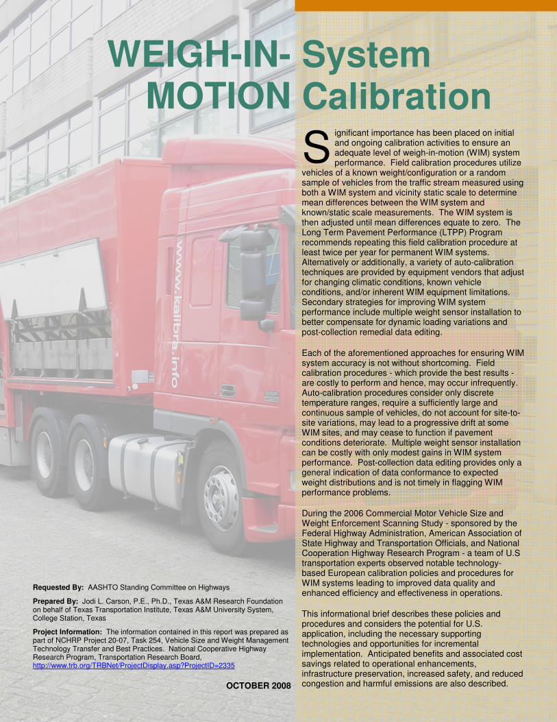
System Calibration ignificant importance has been placed on initial and ongoing calibration activities to ensure an adequate level of weigh-in-motion (WIM) system performance. Field calibration procedures utilize vehicles of a known weight/configuration or a random sample of vehicles from the traffic stream measured using both a WIM system and vicinity static scale to determine mean differences between the WIM system and known/static scale measurements. The WIM system is then adjusted until mean differences equate to zero. The Long Term Pavement Performance (LTPP) Program recommends repeating this field calibration procedure at least twice per year for permanent WIM systems. Alternatively or additionally, a variety of auto-calibration techniques are provided by equipment vendors that adjust for changing climatic conditions, known vehicle conditions, and/or inherent WIM equipment limitations. Secondary strategies for improving WIM system performance include multiple weight sensor installation to better compensate for dynamic loading variations and post-collection remedial data editing.
Each of the aforementioned approaches for ensuring WIM system accuracy is not without shortcoming. Field calibration procedures - which provide the best results - are costly to perform and hence, may occur infrequently. Auto-calibration procedures consider only discrete temperature ranges, require a sufficiently large and continuous sample of vehicles, do not account for site-to-site variations, may lead to a progressive drift at some WIM sites, and may cease to function if pavement conditions deteriorate. Multiple weight sensor installation can be costly with only modest gains in WIM system performance. Post-collection data editing provides only a general indication of data conformance to expected weight distributions and is not timely in flagging WIM performance problems.
During the 2006 Commercial Motor Vehicle Size and Weight Enforcement Scanning Study - sponsored by the Federal Highway Administration, American Association of State Highway and Transportation Officials, and National Cooperation Highway Research Program - a team of U.S transportation experts observed notable technology-based European calibration policies and procedures for WIM systems leading to improved data quality and enhanced efficiency and effectiveness in operations.
This informational brief describes these policies and procedures and considers the potential for U.S. application, including the necessary supporting technologies and opportunities for incremental implementation. Anticipated benefits and associated cost savings related to operational enhancements, infrastructure preservation, increased safety, and reduced congestion and harmful emissions are also described.
S
Requested By: AASHTO Standing Committee on Highways
Prepared By: Jodi L. Carson, P.E., Ph.D., Texas A&M Research Foundation on behalf of Texas Transportation Institute, Texas A&M University System, College Station, Texas
Project Information: The information contained in this report was prepared as part of NCHRP Project 20-07, Task 254, Vehicle Size and Weight Management Technology Transfer and Best Practices. National Cooperative Highway Research Program, Transportation Research Board, http://www.trb.org/TRBNet/ProjectDisplay.asp?ProjectID=2335
OCTOBER 2008
Notable Policies and Procedures Several of the calibration procedures observed in Europe mimic those used in the U.S., including field calibration with vehicles of a known weight and auto-calibration. Unique observations included: continuous, ongoing calibration procedures performed during mobile enforcement efforts; robust quality assurance procedures; and dynamic calibration procedures, facilitated through the use of a specially-designed vehicle, that eliminate traditional dynamic-to-static measurement adjustments.
Enforcement officials in France and The Netherlands utilize continuous, ongoing calibration procedures to ensure an adequate level of WIM system performance. Under this procedure, static axle weight records obtained by enforcement officials during their scheduled enforcement activities are directly compared for
accuracy to the axle weight records captured by the WIM system for the same vehicles. Static measurements are relayed, in near real-time, to personnel at the WIM site using unique vehicle identification information (i.e., vehicle silhouette and license plate images) and dedicated, short-range communications (DSRC). If an unacceptable level of WIM data error is observed (in The Netherlands, WIM axle weight error rates cannot exceed ±15% for 95% of the aggregate vehicles measured), the problem can be quickly corrected through system calibration or other remedial action. Periodic comparisons between static and WIM system weight records can also be performed on an ongoing basis using archived data records.
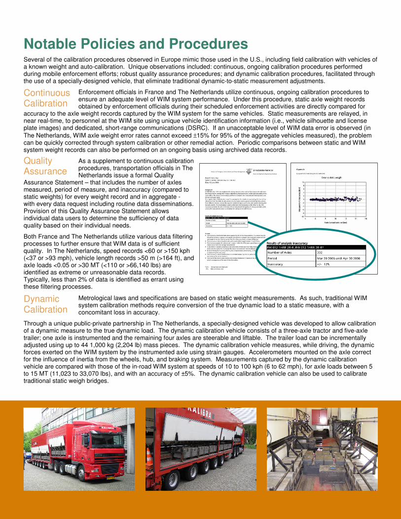
As a supplement to continuous calibration procedures, transportation officials in The Netherlands issue a formal Quality
Assurance Statement – that includes the number of axles measured, period of measure, and inaccuracy (compared to static weights) for every weight record and in aggregate - with every data request including routine data disseminations. Provision of this Quality Assurance Statement allows individual data users to determine the sufficiency of data quality based on their individual needs.
Both France and The Netherlands utilize various data filtering processes to further ensure that WIM data is of sufficient quality. In The Netherlands, speed records <60 or >150 kph (<37 or >93 mph), vehicle length records >50 m (>164 ft), and axle loads <0.05 or >30 MT (<110 or >66,140 lbs) are identified as extreme or unreasonable data records. Typically, less than 2% of data is identified as errant using these filtering processes.
Metrological laws and specifications are based on static weight measurements. As such, traditional WIM system calibration methods require conversion of the true dynamic load to a static measure, with a concomitant loss in accuracy.
Through a unique public-private partnership in The Netherlands, a specially-designed vehicle was developed to allow calibration of a dynamic measure to the true dynamic load. The dynamic calibration vehicle consists of a three-axle tractor and five-axle trailer; one axle is instrumented and the remaining four axles are steerable and liftable. The trailer load can be incrementally adjusted using up to 44 1,000 kg (2,204 lb) mass pieces. The dynamic calibration vehicle measures, while driving, the dynamic forces exerted on the WIM system by the instrumented axle using strain gauges. Accelerometers mounted on the axle correct for the influence of inertia from the wheels, hub, and braking system. Measurements captured by the dynamic calibration vehicle are compared with those of the in-road WIM system at speeds of 10 to 100 kph (6 to 62 mph), for axle loads between 5 to 15 MT (11,023 to 33,070 lbs), and with an accuracy of ±5%. The dynamic calibration vehicle can also be used to calibrate traditional static weigh bridges.
Continuous Calibration
Quality Assurance
Dynamic Calibration

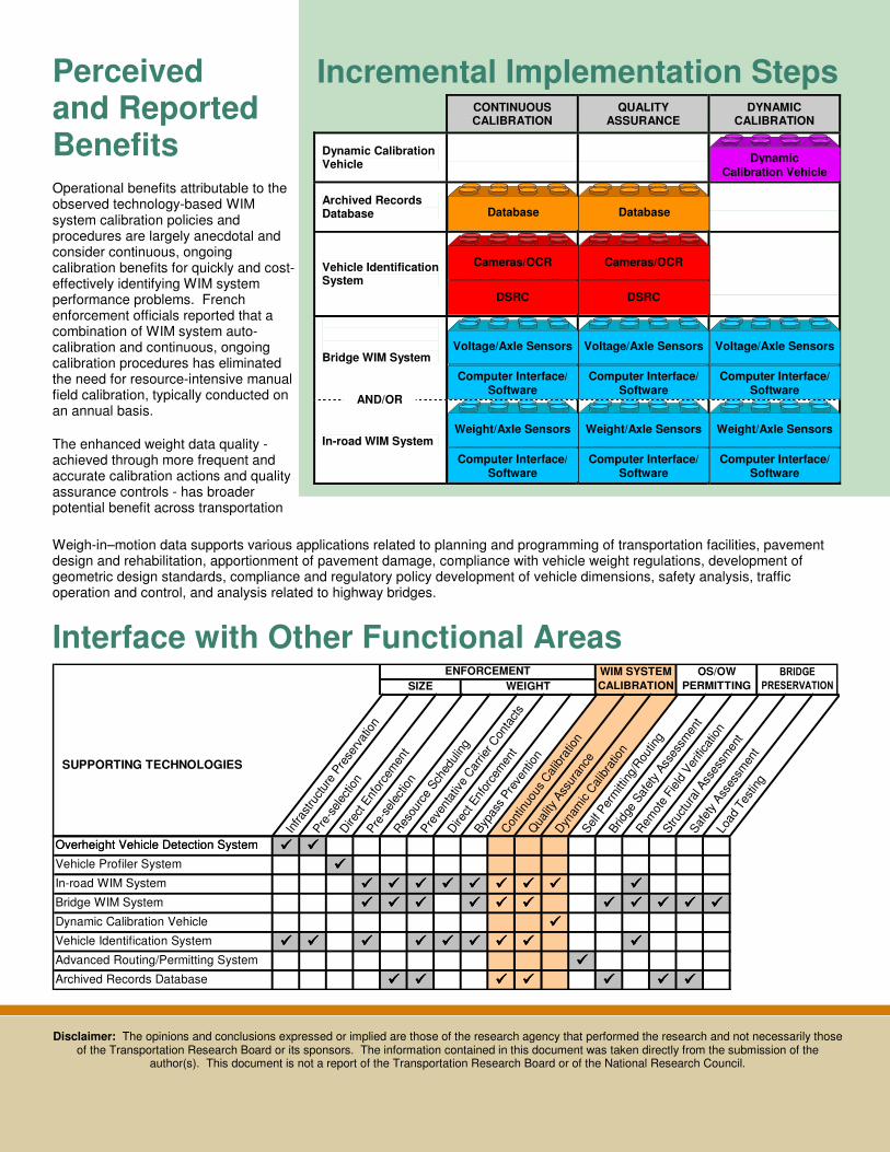
Incremental Implementation Steps
Supporting Technologies
Functions
• Measures and records axles and gross vehicle weight using piezoquartz, piezoceramic, fiber optic, or other sensor technology.
Considerations
• Provides 24/7 monitoring. • May be less accurate than traditional WIM systems (e.g., bending plate or load cell). • Lower cost supports wider implementation, greater geographic coverage.
In-road WIM System
• Weight/Axle Sensors • Computer Interface/
PC Software
Estimated Costs
• $9,000 - $32,500 per lane (for low-cost systems, traditional system costs are higher). • Varies based on weight sensor type, on-site communication requirements. • Requires additional, ongoing maintenance with associated costs.
Functions
• Measures and records vehicle weight using existing roadway structures instrumented with strain transducers or gauges. Bridge deflections are converted to weight measurements.
• Measures and records axles using traditional in-road sensors or through Nothing-on-the-Road/Free-of-Axle Detector (NORFAD) systems.
Considerations
• NORFAD systems offer improved durability and easier installation with no traffic delays. • Requires suitable bridge in a location where WIM data is warranted. • Proven most successful on short, stiff bridge structures. • Structural assessments using strain data may require transducer calibration. • Calibration may require a high expertise level.
Bridge WIM System
• Weight (Voltage)/ Axle Sensors
• Computer Interface/ PC Software
Estimated Costs
• $100,000 - $130,000 per bridge/system. • Varies based on weight sensor type, on-site communication requirements.
Functions
• Captures both vehicle silhouette and license plate images using cameras. • Converts license plate image to numeric data using OCR software. • Transmits images/data via DSRC to portable computer used by enforcement officials.
Considerations
• Conversion of some license plate images to numeric data may result in errors.
Vehicle Identification System
• Camera/ OCR Software
• DSRC/ Portable Computer Estimated Costs
• $52,000 - $80,000 per system. • Varies based on camera type, on-site communication requirements.
Functions
• Supports data-driven scheduling of enforcement resources. • Supports data-driven preventative carrier contacts. • Supports continuous calibration and enhanced data quality. • Encourages long-term performance monitoring.
Considerations
• Requires procedures for quality control.
Archived Records Database
Estimated Costs
• $225,000 - $300,000
Functions
• Calibrates dynamic load measurements to true dynamic (rather than static) loads.
Considerations
• May be used to calibrate traditional static weigh bridges. Dynamic Calibration Vehicle
Estimated Costs
• $1.72 million for vehicle construction. • $6,300 per in-service day.
Incremental Implementation Steps
Interface with Other Functional Areas BRIDGE
PRESERVATION
WIM SYSTEM
CALIBRATION
OS/OW
PERMITTINGSIZE WEIGHT
SUPPORTING TECHNOLOGIES
ENFORCEMENT
Infra
stru
ctur
e Pre
serv
atio
n
Pre
-sel
ectio
nD
irect
Enf
orce
men
t
Pre
-sel
ectio
nR
esou
rce
Sch
edul
ing
Pre
vent
ativ
e C
arrie
r Con
tact
s
Dire
ct E
nfor
cem
ent
Byp
ass
Pre
vent
ion
Con
tinuo
us C
alib
ratio
n
Qua
lity
Ass
uran
ce
Dyn
amic
Cal
ibra
tion
Sel
f Per
mitt
ing/
Rou
ting
Brid
ge S
afet
y Ass
essm
ent
Rem
ote
Fiel
d Ver
ifica
tion
Stru
ctur
al A
sses
smen
t
Saf
ety
Ass
essm
ent
Load
Tes
ting
Overheight Vehicle Detection System
SUPPORTING TECHNOLOGIES
���� ����
����
���� ���� ���� ���� ���� ���� ���� ���� ����
���� ���� ���� ���� ���� ���� ���� ���� ���� ���� ����
����
���� ���� ���� ���� ���� ���� ���� ���� ����
����
���� ���� ���� ���� ���� ���� ����Archived Records Database
Vehicle Identification System
Advanced Routing/Permitting System
Vehicle Profiler System
Bridge WIM System
In-road WIM System
Dynamic Calibration Vehicle
Overheight Vehicle Detection System
CONTINUOUS CALIBRATION
QUALITY ASSURANCE
DYNAMIC CALIBRATION
Dynamic Calibration Vehicle
Archived Records Database
Vehicle Identification System
Bridge WIM System
In-road WIM System
Dynamic Calibration Vehicle
Database Database
DSRC
Cameras/OCR
DSRC
Cameras/OCR
Computer Interface/ Software
Voltage/Axle Sensors
Computer Interface/ Software
Voltage/Axle Sensors
Computer Interface/ Software
Voltage/Axle Sensors
Computer Interface/ Software
Weight/Axle Sensors
Computer Interface/ Software
Weight/Axle Sensors
Computer Interface/ Software
Weight/Axle Sensors
Perceived and Reported Benefits Operational benefits attributable to the observed technology-based WIM system calibration policies and procedures are largely anecdotal and consider continuous, ongoing calibration benefits for quickly and cost-effectively identifying WIM system performance problems. French enforcement officials reported that a combination of WIM system auto-calibration and continuous, ongoing calibration procedures has eliminated the need for resource-intensive manual field calibration, typically conducted on an annual basis.
The enhanced weight data quality - achieved through more frequent and accurate calibration actions and quality assurance controls - has broader potential benefit across transportation and enforcement agencies.
Weigh-in–motion data supports various applications related to planning and programming of transportation facilities, pavement design and rehabilitation, apportionment of pavement damage, compliance with vehicle weight regulations, development of geometric design standards, compliance and regulatory policy development of vehicle dimensions, safety analysis, traffic operation and control, and analysis related to highway bridges.
Disclaimer: The opinions and conclusions expressed or implied are those of the research agency that performed the research and not necessarily those of the Transportation Research Board or its sponsors. The information contained in this document was taken directly from the submission of the
author(s). This document is not a report of the Transportation Research Board or of the National Research Council.
AND/OR