Weekly Testing of Dedicated Stairwell Pressurization Fans ...
30
1 Weekly Testing of Dedicated Stairwell Pressurization Fans- Metasys® System Extended Architecture Application Note Document Introduction . . . . . . . . . . . . . . . . . . . . . . . . . . . . . . . . . . . . . . . . . . . . . . . . . 3 Related Documentation . . . . . . . . . . . . . . . . . . . . . . . . . . . . . . . . . . . . . . . . . . . . . . . . . 3 Application Overview . . . . . . . . . . . . . . . . . . . . . . . . . . . . . . . . . . . . . . . . . . . . . . . . . . 4 Automatic Smoke Control During Weekly Testing . . . . . . . . . . . . . . . . . . . . . . . . . . . . . . 4 Manual Smoke Control During Testing . . . . . . . . . . . . . . . . . . . . . . . . . . . . . . . . . . . . . . . 4 Smoke Control Command Priorities . . . . . . . . . . . . . . . . . . . . . . . . . . . . . . . . . . . . . . . . . 4 Assigning the Fire Object Category to Smoke Control Objects . . . . . . . . . . . . . . . . . . . 5 Security Administration System. . . . . . . . . . . . . . . . . . . . . . . . . . . . . . . . . . . . . . . . . . . . . 5 Roles and User Accounts Overview . . . . . . . . . . . . . . . . . . . . . . . . . . . . . . . . . . . . . . . . . . . 6 UUKL Smoke Control Security Administration Details . . . . . . . . . . . . . . . . . . . . . . . . . . . . . . 6 Security Administration Detailed Procedures . . . . . . . . . . . . . . . . . . . . . . . . . . . . . . . . . . . . . 8 Creating a New Role . . . . . . . . . . . . . . . . . . . . . . . . . . . . . . . . . . . . . . . . . . . . . . . . . . . . . . . . . . . 8 Creating a New User Account . . . . . . . . . . . . . . . . . . . . . . . . . . . . . . . . . . . . . . . . . . . . . . . . . . . . 8 Configuring User Profiles . . . . . . . . . . . . . . . . . . . . . . . . . . . . . . . . . . . . . . . . . . . . . . . . . . . . . . . . 8 Configuring Role Properties . . . . . . . . . . . . . . . . . . . . . . . . . . . . . . . . . . . . . . . . . . . . . . . . . . . . . 8 Assigning System Access Permissions . . . . . . . . . . . . . . . . . . . . . . . . . . . . . . . . . . . . . . . . . . . . . 8 Design Considerations . . . . . . . . . . . . . . . . . . . . . . . . . . . . . . . . . . . . . . . . . . . . . . . . . 9 Smoke Control NAE Design Considerations . . . . . . . . . . . . . . . . . . . . . . . . . . . . . . . . . . . 9 Field Controller Design Considerations . . . . . . . . . . . . . . . . . . . . . . . . . . . . . . . . . . . . . . 9 Field Controller Points . . . . . . . . . . . . . . . . . . . . . . . . . . . . . . . . . . . . . . . . . . . . . . . . 11 Point List . . . . . . . . . . . . . . . . . . . . . . . . . . . . . . . . . . . . . . . . . . . . . . . . . . . . . . . . . . . . . . . 11 Smoke Control NAE Application . . . . . . . . . . . . . . . . . . . . . . . . . . . . . . . . . . . . . . . . 12 Application File Location . . . . . . . . . . . . . . . . . . . . . . . . . . . . . . . . . . . . . . . . . . . . . . . . . 12 Metasys System Extended Architecture Objects . . . . . . . . . . . . . . . . . . . . . . . . . . . . . . 12 Stairwell Fan 1 . . . . . . . . . . . . . . . . . . . . . . . . . . . . . . . . . . . . . . . . . . . . . . . . . . . . . . . . . . 12 Weekly Stairwell Fan Test Logic . . . . . . . . . . . . . . . . . . . . . . . . . . . . . . . . . . . . . . . . . . . 18 Weekly Stairwell Fan Test Alarm Screens . . . . . . . . . . . . . . . . . . . . . . . . . . . . . . . . . . . . 23 Weekly Testing of Dedicated Stairwell Pressurization Fans- Metasys® System Extended Architecture Application Note Code No. LIT-1201739 Release 1.2 Issued Date July 30, 2004 Supersedes
Transcript of Weekly Testing of Dedicated Stairwell Pressurization Fans ...

1Weekly Testing of Dedicated Stairwell Pressurization Fans- Metasys®System Extended Architecture Application Note
Document Introduction . . . . . . . . . . . . . . . . . . . . . . . . . . . . . . . . . . . . . . . . . . . . . . . . . 3Related Documentation. . . . . . . . . . . . . . . . . . . . . . . . . . . . . . . . . . . . . . . . . . . . . . . . . 3Application Overview . . . . . . . . . . . . . . . . . . . . . . . . . . . . . . . . . . . . . . . . . . . . . . . . . . 4
Automatic Smoke Control During Weekly Testing . . . . . . . . . . . . . . . . . . . . . . . . . . . . . . 4
Manual Smoke Control During Testing . . . . . . . . . . . . . . . . . . . . . . . . . . . . . . . . . . . . . . . 4
Smoke Control Command Priorities . . . . . . . . . . . . . . . . . . . . . . . . . . . . . . . . . . . . . . . . . 4
Assigning the Fire Object Category to Smoke Control Objects . . . . . . . . . . . . . . . . . . . 5
Security Administration System. . . . . . . . . . . . . . . . . . . . . . . . . . . . . . . . . . . . . . . . . . . . . 5
Roles and User Accounts Overview . . . . . . . . . . . . . . . . . . . . . . . . . . . . . . . . . . . . . . . . . . . 6
UUKL Smoke Control Security Administration Details . . . . . . . . . . . . . . . . . . . . . . . . . . . . . . 6
Security Administration Detailed Procedures. . . . . . . . . . . . . . . . . . . . . . . . . . . . . . . . . . . . . 8
Creating a New Role . . . . . . . . . . . . . . . . . . . . . . . . . . . . . . . . . . . . . . . . . . . . . . . . . . . . . . . . . . . 8
Creating a New User Account . . . . . . . . . . . . . . . . . . . . . . . . . . . . . . . . . . . . . . . . . . . . . . . . . . . . 8
Configuring User Profiles . . . . . . . . . . . . . . . . . . . . . . . . . . . . . . . . . . . . . . . . . . . . . . . . . . . . . . . . 8
Configuring Role Properties . . . . . . . . . . . . . . . . . . . . . . . . . . . . . . . . . . . . . . . . . . . . . . . . . . . . . 8
Assigning System Access Permissions . . . . . . . . . . . . . . . . . . . . . . . . . . . . . . . . . . . . . . . . . . . . . 8
Design Considerations . . . . . . . . . . . . . . . . . . . . . . . . . . . . . . . . . . . . . . . . . . . . . . . . . 9Smoke Control NAE Design Considerations. . . . . . . . . . . . . . . . . . . . . . . . . . . . . . . . . . . 9
Field Controller Design Considerations . . . . . . . . . . . . . . . . . . . . . . . . . . . . . . . . . . . . . . 9
Field Controller Points . . . . . . . . . . . . . . . . . . . . . . . . . . . . . . . . . . . . . . . . . . . . . . . . 11Point List. . . . . . . . . . . . . . . . . . . . . . . . . . . . . . . . . . . . . . . . . . . . . . . . . . . . . . . . . . . . . . . 11
Smoke Control NAE Application . . . . . . . . . . . . . . . . . . . . . . . . . . . . . . . . . . . . . . . . 12Application File Location . . . . . . . . . . . . . . . . . . . . . . . . . . . . . . . . . . . . . . . . . . . . . . . . . 12
Metasys System Extended Architecture Objects . . . . . . . . . . . . . . . . . . . . . . . . . . . . . . 12
Stairwell Fan 1 . . . . . . . . . . . . . . . . . . . . . . . . . . . . . . . . . . . . . . . . . . . . . . . . . . . . . . . . . . 12
Weekly Stairwell Fan Test Logic . . . . . . . . . . . . . . . . . . . . . . . . . . . . . . . . . . . . . . . . . . . 18
Weekly Stairwell Fan Test Alarm Screens. . . . . . . . . . . . . . . . . . . . . . . . . . . . . . . . . . . . 23
Weekly Testing of Dedicated Stairwell Pressurization Fans- Metasys® System Extended ArchitectureApplication Note Code No. LIT-1201739
Release 1.2Issued Date July 30, 2004
Supersedes

Weekly Testing of Dedicated Stairwell Pressurization Fans- Metasys® System Extended Architecture Application Note
2
Weekly Stairwell Test Schedule . . . . . . . . . . . . . . . . . . . . . . . . . . . . . . . . . . . . . . . . . . . . 28

Weekly Testing of Dedicated Stairwell Pressurization Fans - Metasys® System Extended Architecture Application Note
3
Weekly Testing of Dedicated Stairwell Pressurization Fans - Metasys® System Extended ArchitectureApplication Note
Document IntroductionThis application is designed to provide a weekly test of a dedicated stairwell pressurization fan automatically. The weekly test is achieved with the field controller application and the smoke control NAE application described in this document, with manual override of the smoke control logic provided by the Fire Fighter’s Smoke Control Station (FSCS).
Note: Elevator shafts should be treated like stairwells and be positively pressurized to prevent migration of smoke into the elevator shaft and through the building. Even though this application does not consider elevator shaft pressurization, you may want to include this type of control if the building uses elevators.
Related Documentation Table 1: Related Documentation For Information On Refer To LIT No./Part No.General smoke control information Metasys System Extended Architecture
Smoke Control System Technical BulletinLIT-1201684
Specific wiring requirements Metasys System Extended Architecture Smoke Control Wiring Technical Bulletin
LIT-1201753
Logic programming for the DX-9100 controller
GX-9100 Software Configuration Tool Technical Bulletin
LIT-6364060
Single story enclosed shopping mall smoke control
Single Story Enclosed Shopping Mall Smoke Control with FSCS Override – Metasys System Extended Architecture Application Note
LIT-1201736
Multi-story building smoke control Multi-Story Building Smoke Control with FSCS Override - Metasys System Extended Architecture Application Note
LIT-1201737
Warehouse smoke control Warehouse Smoke Control with FSCS Override – Metasys System Extended Architecture Application Note
LIT-1201738
Weekly testing of dedicated smoke control dampers
Weekly Testing of Dedicated Smoke Control Dampers – Metasys System Extended Architecture Application Note
LIT-1201743
UL 864 UUKL requirements MSEA UL 864 UUKL Compliance Checklist LIT-1201754
Weekly Testing of Dedicated Stairwell Pressurization Fans - Metasys® System Extended Architecture Application Note
4
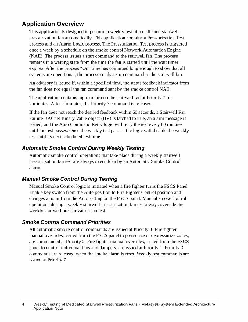
Application OverviewThis application is designed to perform a weekly test of a dedicated stairwell pressurization fan automatically. This application contains a Pressurization Test process and an Alarm Logic process. The Pressurization Test process is triggered once a week by a schedule on the smoke control Network Automation Engine (NAE). The process issues a start command to the stairwell fan. The process remains in a waiting state from the time the fan is started until the wait timer expires. After the process “On” time has continued long enough to show that all systems are operational, the process sends a stop command to the stairwell fan.
An advisory is issued if, within a specified time, the status feedback indicator from the fan does not equal the fan command sent by the smoke control NAE.
The application contains logic to turn on the stairwell fan at Priority 7 for 2 minutes. After 2 minutes, the Priority 7 command is released.
If the fan does not reach the desired feedback within 60 seconds, a Stairwell Fan Failure BACnet Binary Value object (BV) is latched to true, an alarm message is issued, and the Auto Command Retry logic will retry the test every 60 minutes until the test passes. Once the weekly test passes, the logic will disable the weekly test until its next scheduled test time.
Automatic Smoke Control During Weekly TestingAutomatic smoke control operations that take place during a weekly stairwell pressurization fan test are always overridden by an Automatic Smoke Control alarm.
Manual Smoke Control During TestingManual Smoke Control logic is initiated when a fire fighter turns the FSCS Panel Enable key switch from the Auto position to Fire Fighter Control position and changes a point from the Auto setting on the FSCS panel. Manual smoke control operations during a weekly stairwell pressurization fan test always override the weekly stairwell pressurization fan test.
Smoke Control Command PrioritiesAll automatic smoke control commands are issued at Priority 3. Fire fighter manual overrides, issued from the FSCS panel to pressurize or depressurize zones, are commanded at Priority 2. Fire fighter manual overrides, issued from the FSCS panel to control individual fans and dampers, are issued at Priority 1. Priority 3 commands are released when the smoke alarm is reset. Weekly test commands are issued at Priority 7.

Weekly Testing of Dedicated Stairwell Pressurization Fans - Metasys® System Extended Architecture Application Note
5
Assigning the Fire Object Category to Smoke Control ObjectsYou must assign every object used specifically for smoke control as a Fire object. This limits the control of smoke control devices and points to authorized Fire operators.Use the pull down menu to assign the Fire object category (Figure 1).
Security Administration SystemThe Security Administration system authenticates and authorizes users of Metasys® system extended architecture applications. The Security Administrator is a browser-based interface that manages all accounts.
Use the Security Administrator System to authenticate and authorize users on the Metasys system extended architecture. The Security Administrator creates User Accounts and Roles, and assigns access permissions to each user of the Metasys system extended architecture.
!WARNING: Risk of serious injury or death if a smoke control object is not assigned as a Fire object! In the event of a fire or smoke control event, devices or points used for smoke control that are not assigned as Fire objects allow those devices and points to be controlled by non-fire authorized operators. It is imperative that every smoke control device or point be assigned as a Fire object.
Figure 1: Assigning the Fire Object to Smoke Control Objects

Weekly Testing of Dedicated Stairwell Pressurization Fans - Metasys® System Extended Architecture Application Note
6
Roles and User Accounts OverviewSecurity is based on User Accounts and Roles. Roles are groups of users with a specific function within the Metasys system. To access the system, an individual provides a user account and the correct password. Use letters, numbers, or symbols to create user account passwords.
Use the Login button from the logon prompt to send the user’s credentials. A unique Session generates when the user’s credentials match the logon requirements.
UUKL Smoke Control Security Administration DetailsUUKL smoke control requires that only operators designated as fire operators be able to control the smoke control system. This required the creation of four new roles:
1. Administrator - This is the highest level of control and allows site control of all HVAC and Fire features.Fire Administrator - This role is a fire manager level setting. It allows for full system control, including system modification or configuration.
2. Fire Administrator - This role is a fire manager level setting. It allows for full system control, including system modification or configuration.
Figure 2: Fire Administrator Access Permissions

Weekly Testing of Dedicated Stairwell Pressurization Fans - Metasys® System Extended Architecture Application Note
7
3. Fire User - This role is for most fire field technicians and allows system control and alarm acknowledgement, but not system modification or configuration.
4. Fire Limited - This is the lowest of the permissions and only allows the operator to view fire/smoke control devices and alarms.
Figure 3: Fire User Access Permissions
Figure 4: Fire Limited Access Permissions

Weekly Testing of Dedicated Stairwell Pressurization Fans - Metasys® System Extended Architecture Application Note
8
Security Administration Detailed Procedures
Creating a New RoleTo create a new role:
1. From the Security Administration menu bar, select Insert > New Role. The New Role dialog box appears.
2. Fill in the information.
3. Click OK. The New Role appears in the tree.
Creating a New User AccountTo create a new user account:
1. From the Security Administration menu bar, select Insert > New User. The User Properties tab appears.
2. Fill in the information.
3. Click OK. The New User appears in the tree.
Configuring User ProfilesTo configure a user profile:
1. Select the user whom you wish to configure.
2. From the menu bar, select Edit > Properties. The User Properties tab appears.
3. Modify the desired user information.
4. Click OK.
Configuring Role PropertiesTo configure role properties:
1. Select the user whom you wish to configure.
2. From the menu bar, select Edit > Properties. The User Properties tab appears.
3. Select the Roles tab, then select an Available Role.
4. Click Add. The selected role appears in the Assigned Role list box.
5. Click OK.
Assigning System Access PermissionsTo assign system access permissions:
1. Select the user whom you wish to assign system access permissions.
2. From the main menu, select Edit > System Access Permissions. The System Access Permission dialog box appears.
3. Select an available privilege.
4. Click Add, then click OK to assign the user’s System Access Permissions.

Weekly Testing of Dedicated Stairwell Pressurization Fans - Metasys® System Extended Architecture Application Note
9
Design ConsiderationsThis DX9100 and Smoke Control NAE application, as it exists in the Metasys System Extended Architecture Smoke Control Library, complies with the UL 864 UUKL Smoke Listing. However, you are responsible for ensuring that the application complies with state and local regulations, and is approved by the Authority Having Jurisdiction (AHJ). You are also responsible for configuring all of the smoke control components, as well as the programming of those components, in order to comply with the UL 864 UUKL Smoke Listing as documented herein.
Smoke Control NAE Design ConsiderationsKeep the following design considerations in mind when designing a weekly dedicated stairwell pressurization fan test application. In addition, please refer to the Metasys System Extended Architecture Smoke Control System Technical Bulletin (LIT-1201684).
• The smoke control NAE reports critical alarms based on the alarm condition, and the alarm can only be cleared by resetting from the Intelligent Fire Controller (IFC) panel or the Firefighter’s Smoke Control Station (FSCS).
• You must define the hardware location for each object
• You must name each object with a descriptive name that is unique in the system.
• A “Programming In Progress” BACnet Binary Value object (BV) point is required. You must set this point to true any time you are making changes to the Smoke Control system. This will turn on a Light-Emitting Diode (LED) on the FSCS to let a fire fighter know that changes are being made and the system may not be fully functional. The point must be turned off when changes are complete.
• Response time for individual smoke control components to achieve their desired state of operational mode, exclusive of control system response, should not exceed the following time periods: 60 seconds for fan operation at the desired state plus 90 seconds to annunciate. (Control system response is the time from automatic detection of a smoke condition to the issuing of an appropriate command to the equipment.)
Field Controller Design ConsiderationsThere are a number of UL® Listed field controllers suitable for use in this Metasys System extended architecture smoke control application. This document addresses the field points that must be programmed into the field controller, and does not specify which controller to use. It is up to design engineer to select the field controller, and up to the installation technician to program these required points into the controller.
Weekly Testing of Dedicated Stairwell Pressurization Fans - Metasys® System Extended Architecture Application Note
10
The following field controllers are UL® Listed for Smoke Control for Metasys system extended architecture systems:
• AP-VMA Series
• AS-AHU Series
• AS-UNT Series
• AS-VAV Series
• DX 9100
• A field controller needs to provide the following BV points:
• BV command point for each fan
• BV feedback point for each fan
• BV point for the Analog Input (AI) Fuse (Only required for the DX9100)
• BV point for Binary Input (BI) Fuse (Only required for the DX9100)
• Use the following priorities for commands to field controller points:
• 7 – commands from weekly stairwell pressurization fan test
• 3 – commands from automatic smoke control
• 2 – commands from manual smoke control for zone pressurize, depressurize, and purge.
• 1 – commands from manual smoke control for individual points.
• This application can be expanded for a building with more than one stairwell pressurization fan. For further details, please contact Field Support Services in Milwaukee.
• You must define the hardware location for each object
• You must name each object with a descriptive name that is unique in the system.
• An alarm occurs if the command does not equal the condition for any pressurization output. Each Binary Output (BO) for pressurization outputs must be configured to have its own feedback (proof sensor) input. The FSCS indicates when command does not equal condition.
For UL compliance:
• Response time for individual smoke control components to achieve their desired state of operational mode, exclusive of control system response, should not exceed the following time periods: 60 seconds for fan operation at the desired state plus 90 seconds to annunciate. (Control system response is the time from automatic detection of a smoke condition to the issuing of an appropriate command to the equipment.)

Weekly Testing of Dedicated Stairwell Pressurization Fans - Metasys® System Extended Architecture Application Note
11
• For DX-9100 controllers only:
• If DX Digital Inputs (DIs) are used for smoke control, then DI8 must be jumpered and mapped to the smoke control NAE as a normal state of On. If DI8 is off, a critical alarm must be issued at the FSCS to indicate a binary input fuse failure that must be fixed immediately, because the DI is no longer accurate.
• If DX Analog Outputs (AOs) are used for smoke control, then Analog Output 14 (AO14, voltage) must be wired to Analog Input 8 (AI8, voltage) and the AI must be mapped to the smoke control NAE with a low alarm limit of 20%. If the AI goes below 20%, it indicates the AO has failed because of a blown fuse, which drops the AO to 0V and the AI to 0% (low alarm). The DX is downloaded so that the AO is normally at 5V because its source point is an Analog Constant (ACO) with a default of 50.
For specific wiring requirements, refer to Metasys System Extended Architecture Smoke Control System Wiring Technical Bulletin (LIT-1201753).
Field Controller PointsPoint List
Table 2 shows the hardware point requirements for the GX configuration.Table 2: Hardware I/O RequirementsInput Requirements
Hardware Location
Name of Module
Engineer Units
Req? Description
AI1 FUSE ALM/NOR Only for DX-9100
AI1 Fuse Monitor
DI1 FUSE ALM/NOR Only for DX-9100
DI1 Fuse Monitor
DI4 STFN1FB OFF/ON Yes Stairwell Fan 1 Feedback
Output Requirements
Hardware Location
Name of Module
Engineer Units
Req? Description
DO4 STFN1 OFF/ON Yes Stairwell Fan 1

Weekly Testing of Dedicated Stairwell Pressurization Fans - Metasys® System Extended Architecture Application Note
12
Smoke Control NAE ApplicationApplication File Location
This Metasys system extended architecture smoke control application is located on the Metasys Branch Purchase Package (BPP) CD in the Metasys System Extended Architecture Standard Smoke Control Applications directory.
Metasys System Extended Architecture ObjectsThis smoke control NAE application resides on the smoke control NAE and was created with the System Configuration Tool (SCT) to define the required Control System, Interlock, and Multiple Command objects. The Logic Connector Tool (LCT) is used to create the logic within the Control System object.
Stairwell Fan 1The Stairwell Fan 1 main logic in Figure 5 has a Fan system logic block. The Fan block’s inputs on the field controller are the Fan Commanded Value, Fan Present Value, and Stairwell Pressurize Command. Inputs from the FSCS are the On and Off toggle switch status, the Fire Fighter Control Key, Stairwell Fan Trouble Interlock, Stairwell Fan Status Multiple Command Object (MCO), Stairwell Fan Auto Pressurize MCO, and a Zone Depressurize Off command. Outputs are the On, Auto, Off, and Trouble LEDs on the FSCS and an MCO that will command the stairwell fan.
Figure 5: Stairwell Fan 1 Main Logic

Weekly Testing of Dedicated Stairwell Pressurization Fans - Metasys® System Extended Architecture Application Note
13
The expanded Stairwell Fan Test logic block in Figure 6 consists of the FSCS system block and the Fan Trouble Control system block. The FSCS block controls the LEDs on the FSCS panel and commands the field points. The Fan Trouble Control block sets the Fan Trouble LED, and contains the Auto Command Retry logic.
Figure 6: Stairwell Fan Test Block Logic

Weekly Testing of Dedicated Stairwell Pressurization Fans - Metasys® System Extended Architecture Application Note
14
The expanded FSCS system block logic is shown in Figure 7. The On LED is lit only if the FSCS is in Fire Fighter Control and the fan is on. The Off LED is lit only if the FSCS is in Fire Fighter Control and the fan is off. The Auto LED is lit only if the toggle switch is not in the On or Off setting.
If the Fire Fighter Control Key is off, FSCS Request is set to 0. If the Fire Fighter Control Key is on, FSCS Request is set to the following values depending on the position of the Stairwell Fan 1 toggle switch:
• On – 1
• Auto – 0
• Off – 2
Figure 7: Expanded FSCS Block Logic

Weekly Testing of Dedicated Stairwell Pressurization Fans - Metasys® System Extended Architecture Application Note
15
The Fan Trouble Control block logic is shown in Figure 8. The Stairwell Fan 1 Trouble LED is lit if the fan is in smoke control and the fan has not reached its desired setpoint within 60 seconds or, if a DX-9100 controller is used, one of the DX fuses has blown. A fan is in smoke control if, either the field controller is in pressurize or depressurize mode, or, the Fire Fighter Control Key is on and the FSCS toggle switch is set to On or Off.
The Stairwell Fan 1 Trouble Interlock Definition in Figure 9 includes status and reliability of the BI Fuse and AI Fuse, reliability of the supply fan, offline status of the DX, and point that is sends an alarm if the stairwell fan fails.
Note: The BI and AI fuses are only required if you are using a DX-9100 controller.
Figure 8: Expanded Fan Trouble Control Block Logic
Figure 9: Stairwell Fan 1 Trouble Interlock Definition

Weekly Testing of Dedicated Stairwell Pressurization Fans - Metasys® System Extended Architecture Application Note
16
The Stairwell Fan 1 MCO Action Table is shown in (Figure 10). The Stairwell Fan Auto point is a binary point in the field controller to indicate that the Fan is under automatic smoke control. When a fire fighter turns the fan on or off, the Stairwell Fan Auto point is turned off. The Stairwell Fan Command is a point in the field controller to control the fan.
Figure 10: Stairwell Fan 1 MCO Action Table

Weekly Testing of Dedicated Stairwell Pressurization Fans - Metasys® System Extended Architecture Application Note
17
The Stairwell Auto Pressurize MCO Action Table is shown in Figure 11. It pressurizes the stairwell at priority 3 when automatic smoke control is active.When automatic smoke control is not active it releases at priority 3.
Figure 11: Stairwell Auto Pressurize MCO Action Table

Weekly Testing of Dedicated Stairwell Pressurization Fans - Metasys® System Extended Architecture Application Note
18
Weekly Stairwell Fan Test LogicThe Weekly Stairwell Fan Test main logic (Figure 12) contains the Stairwell Fan inputs, the Stairwell Fan Test system logic block, and the Fan Failure and Fan Trouble LED outputs.
The expanded Stairwell Fan Test block is shown in Figure 13.
Figure 12: Weekly Stairwell Fan Test Main Logic Screen
Figure 13: Expanded Stairwell Fan Test Block Logic
Weekly Testing of Dedicated Stairwell Pressurization Fans - Metasys® System Extended Architecture Application Note
19
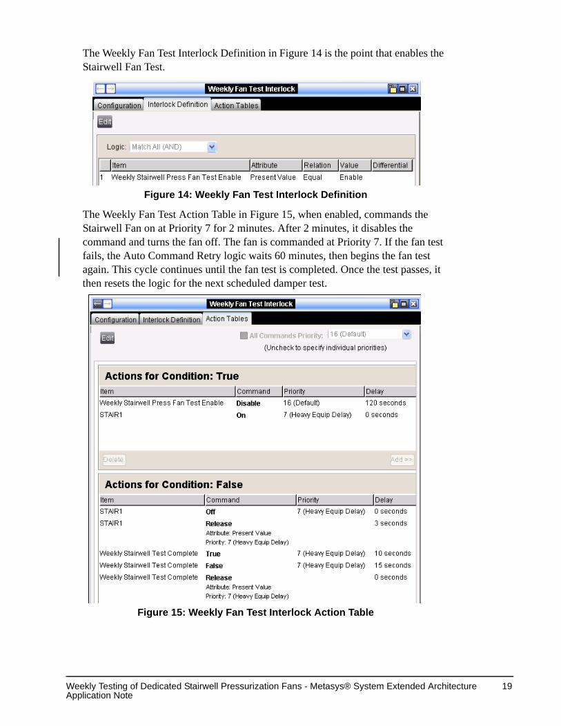
The Weekly Fan Test Interlock Definition in Figure 14 is the point that enables the Stairwell Fan Test.
The Weekly Fan Test Action Table in Figure 15, when enabled, commands the Stairwell Fan on at Priority 7 for 2 minutes. After 2 minutes, it disables the command and turns the fan off. The fan is commanded at Priority 7. If the fan test fails, the Auto Command Retry logic waits 60 minutes, then begins the fan test again. This cycle continues until the fan test is completed. Once the test passes, it then resets the logic for the next scheduled damper test.
Figure 14: Weekly Fan Test Interlock Definition
Figure 15: Weekly Fan Test Interlock Action Table

Weekly Testing of Dedicated Stairwell Pressurization Fans - Metasys® System Extended Architecture Application Note
20
If the fan test fails, the failure is latched by the fan logic in Figure 13. After correcting the reason the fan failed, you must unlatch the failure. The Fan Failure Reset Interlock Definition is shown in Figure 16 is used to reset the latch. Ten seconds after Fan Failure Reset is set to true, this interlock will set Fan Failure Reset back to false. The Weekly Stairwell Pressurization Fan Test will release the latched alarm while Fan Failure Reset is true. The Fan Failure is latched until the Fan Failure Reset is commanded to true on the NAE.
The Fan Failure Reset Interlock Action Table is shown in Figure 17. When the fan test has finished, the fan reset has to be commanded at the NAE to active, then it will reset itself to inactive and reset the logic for the next scheduled fan test.
The Terminate Testing Interlock in Figure 18 terminates the test if any of the following happens:
• automatic smoke mode begins
• pressurization is turned on
• the fan fails to meet command
• the FSCS switch for the point is in any position other than Auto
Figure 16: Fan Failure Reset Interlock Definition
Figure 17: Fan Failure Reset Interlock Action Table

Weekly Testing of Dedicated Stairwell Pressurization Fans - Metasys® System Extended Architecture Application Note
21
The Terminate Testing Interlock Action Table is shown in Figure 19. When the fan test has been terminated, the interlock stops the Weekly Stairwell Fan Test Complete message, and then releases the fan test. This triggers the Weekly Stairwell Fan Test Terminated alarm message. The Fan Failure Reset will then rerun the fan test every 60 minutes until the test passes. Once the test passes, it resets the logic for the next scheduled fan test.
Figure 18: Terminate Testing Interlock Definition
Figure 19: Terminate Testing Action Table

Weekly Testing of Dedicated Stairwell Pressurization Fans - Metasys® System Extended Architecture Application Note
22
The Fan Auto Status Interlock Definition is shown in Figure 20. During a weekly stairwell fan test, this interlock prevents a trouble condition, related to a weekly fan test failure, from lighting a Trouble LED when:
• the fan switch is in any position other than Auto
• auto smoke control mode is invoked
• manual smoke control mode is invoked
The Trouble LED will light if any of the above conditions result in a smoke control condition not related to the weekly test.
After the smoke control condition clears itself, the Trouble LED will relight with the trouble from the Weekly Test Failure.
Figure 20: Fan Auto Status Interlock Action Table

Weekly Testing of Dedicated Stairwell Pressurization Fans - Metasys® System Extended Architecture Application Note
23
Weekly Stairwell Fan Test Alarm Screens When the scheduled date and time to execute the weekly test is reached, the weekly test begins. A Weekly Test of Stairwell Pressurization Fans Enabled alarm message is generated at the smoke control NAE to notify you the test is in progress, see Figure 21.
Figure 21: Weekly Stairwell Pressurization Fan Test Enable Alarm Screen
Weekly Testing of Dedicated Stairwell Pressurization Fans - Metasys® System Extended Architecture Application Note
24
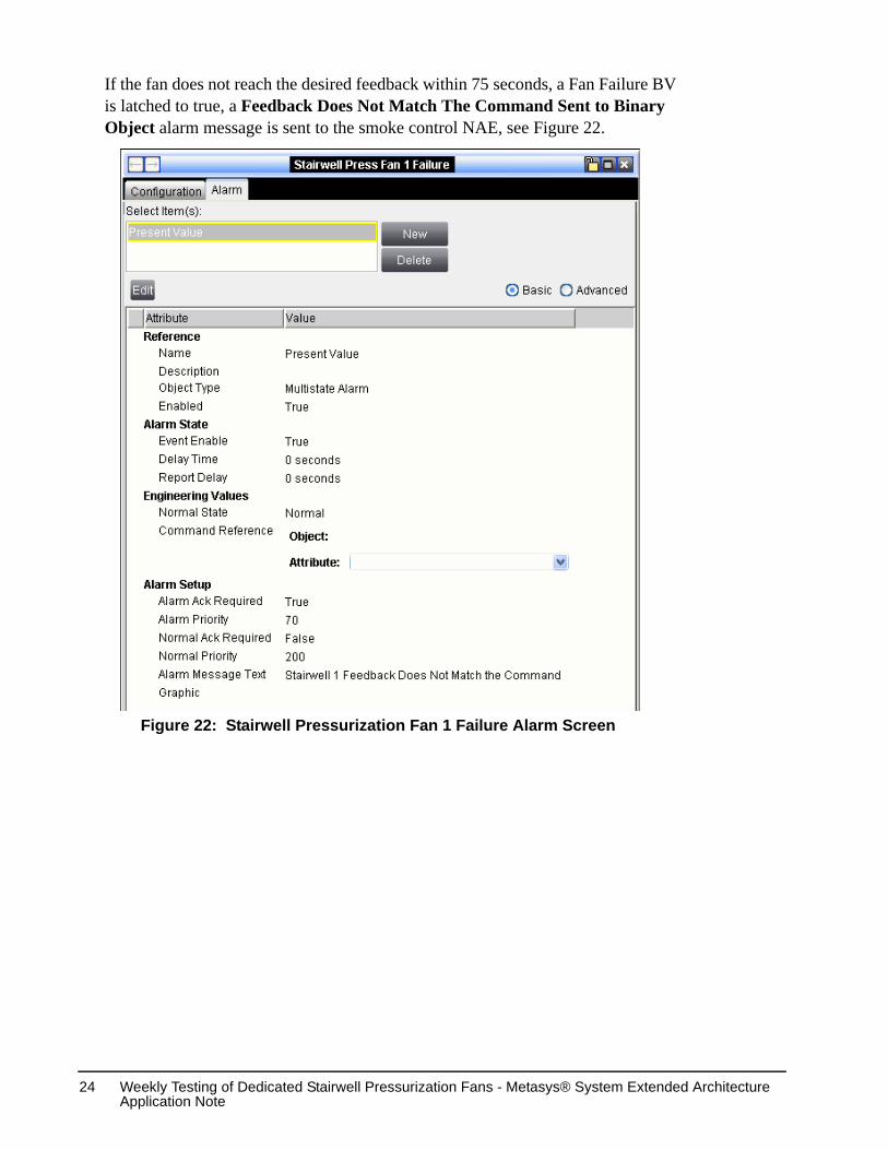
If the fan does not reach the desired feedback within 75 seconds, a Fan Failure BV is latched to true, a Feedback Does Not Match The Command Sent to Binary Object alarm message is sent to the smoke control NAE, see Figure 22.
Figure 22: Stairwell Pressurization Fan 1 Failure Alarm Screen

Weekly Testing of Dedicated Stairwell Pressurization Fans - Metasys® System Extended Architecture Application Note
25
If the weekly test terminates, the “Stairwell 1 Weekly Dedicated Testing terminated: due to the point is in Automatic Smoke Control, Manual Smoke Control, or Feedback does not match command” alarm message is sent to the smoke control NAE, see Figure 23.
Figure 23: Weekly Test Terminated Alarm Screen

Weekly Testing of Dedicated Stairwell Pressurization Fans - Metasys® System Extended Architecture Application Note
26
If the weekly test fails it, the “Feedback Does Not Match the Command Sent to Binary Object” alarm message is sent to the smoke control NAE, see Figure 24.
Figure 24: Stairwell Fan Failure Reset Alarm Screen

Weekly Testing of Dedicated Stairwell Pressurization Fans - Metasys® System Extended Architecture Application Note
27
When the weekly test is completed, the “Stairwell 1 Weekly Stairwell Test Completed” alarm message is sent to the smoke control NAE, see Figure 25.
Figure 25: Weekly Stairwell Test Complete Alarm Screen

Weekly Testing of Dedicated Stairwell Pressurization Fans - Metasys® System Extended Architecture Application Note
28
Weekly Stairwell Test ScheduleThe Weekly Stairwell Pressurization Fan Test must be setup in a schedule before it can be run. The Weekly Schedule screen in Figure 26 sets the date and time to run the weekly fan test.
Figure 26: Weekly Test Schedule

Published in U.S.A. www.johnsoncontrols.com
Controls Group507 E. Michigan StreetMilwaukee, WI 53202
Metasys® is a registered trademark of Johnson Controls, Inc.All other marks herein are the marks of their respective owners.
© 2004 Johnson Controls, Inc.
Weekly Testing of Dedicated Stairwell Pressurization Fans - Metasys® System Extended Architecture Application Note
29
The Weekly Test Schedule Exception (Figure 27), when configured, allows an exception to the scheduled Weekly Fan Test.
The Scheduled Items screen in Figure 28 shows the Weekly Stairwell Pressurization Fan Test, and any other scheduled programs.
Figure 27: Weekly Test Exception Schedule
Figure 28: Weekly Stairwell Pressurization Fan Test Schedule

Weekly Testing of Dedicated Stairwell Pressurization Fans - Metasys® System Extended Architecture Application Note
30